1. Introduction
The lateral pressure of the retaining wall is a key factor affecting the safety and stability of the retaining wall. An accurate estimation of the earth pressure behind a retaining wall is the premise of rational design. Coulomb’s and Rankine’s earth pressure theory have been used by engineering designers until now because of their simple form and clear concept. Both of them assume that the backfill behind the wall is semi-infinite and is fully saturated or dry. Furthermore, the earth pressure obtained by the two theories is linearly distributed along the depth. However, it is proven that the active earth pressure distribution behind the wall is nonlinear due to the rough wall–soil interfaces [
1,
2,
3,
4,
5].
With the rapid development of urban construction, underground buildings are becoming more and more intensive, so that the backfills behind many retaining walls cannot meet the conditions of semi-infinite soil. The adjacent underground structures prevent the sliding surface in the backfill from fully developing to the backfill surface, resulting in a large difference between the earth pressure behind the wall and that in the semi-infinite soil case. Several studies have demonstrated that the active earth pressure acting on the retaining wall decreases with the narrowing of the backfill behind the wall [
3,
5,
6,
7,
8,
9,
10,
11,
12]. In addition, some scholars have discussed the shape of the slip surface in the soil under the condition of narrow backfill. A simple but effective method is to assume that the linear sliding surface is truncated by the adjacent wall to form a trapezoidal sliding wedge [
5,
13]. Greco [
14] believed that the sliding surface will reflect and form a multi fold line failure mode after it develops to the adjacent wall. Yang et al. [
15] conducted a series of model tests and observed that the slip surfaces are curvilinear planes developed from the heel of the retaining wall to the crest of the backfill.
On the other hand, after the soil arch theory was put forward by Janssen [
16], the relevant earth pressure research was carried out by many geotechnical scholars. Handy [
17] defined the active soil arch as the trajectory of small principal stress, assumed that the trajectory of the soil arch between two parallel retaining walls is catenary, and established the expression of the earth pressure distribution behind the wall by the slice method. Paik and Salgado [
18] assumed that the soil arch is a circular arc, and the sliding surface of the backfill is the Rankine sliding surface, but the deflection of the principal stress at the sliding surface is not considered. Goel [
19] assumed the soil arch as a parabola and solved the theoretical expression of active earth pressure in the form of polar coordinates in the case of the linear failure mode and parabola failure mode. Many subsequent studies have proven that the soil arching effect cannot be ignored in the calculation of earth pressure [
9,
20,
21,
22].
Additionally, due to the complex natural geological environment, various retaining structures are inevitably backfilled by unsaturated soil. In this case, the traditional earth pressure theories treat backfills as completely saturated or dry soils. Nevertheless, many engineering cases demonstrate that economic and safe retaining structure design can only be carried out if the lateral pressure change caused by the change of matric suction in unsaturated backfill is reasonably considered [
23,
24,
25]. The following work has been carried out by researchers: Pufahl et al. [
26] obtained the Rankine earth pressure solution of unsaturated soil based on the strength theory of two stress variables [
27]. Liang et al. [
28] combined the strength theory of unsaturated soil with the Coulomb earth pressure theory, and obtained the unified solution of Coulomb earth pressure in unsaturated soil. Since then, the limit equilibrium method has been widely used to solve the earth pressure of unsaturated soil [
24,
29,
30]. Moreover, the slip line theory [
31,
32] and the upper bound method of limit analysis [
33,
34,
35] have also been extended to the calculation of earth pressure in unsaturated soils. However, most unsaturated earth pressure theories still assume that the backfill is in semi-infinite soil conditions when analyzing the finite fill behind the wall, which is seriously inconsistent with the actual situation, resulting in too conservative calculation results. In addition, two ideas are generally adopted for the theoretical derivation of unsaturated earth pressure at present. One is based on the traditional Coulomb earth pressure method, and the overall sliding wedge is used to solve the problem, but the distribution of earth pressure cannot be obtained. The other method is to use the horizontal thin-layer slicing method, but most theories do not consider the comprehensive influence of the soil arching effect and interlayer shear stress in the analysis, resulting in a large deviation between the predicted results and the actual situation.
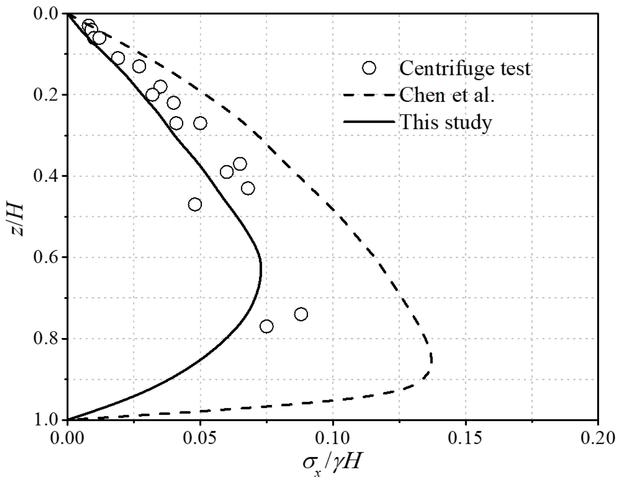
Based on the above analysis, this study takes the narrow unsaturated backfill as the analysis object, assumes that the trajectory of small principal stress is an arc and the soil slip surface behind the wall is a Coulomb slip surface, and the Mohr stress circle is used to calculate the average vertical stress and shear stress of the horizontal interlayer; on this basis, the expression of active earth pressure, its resultant force and the height of the action point is given by the horizontal thin layer analysis method, and it is compared with the model test and other theoretical results in the relevant literature. At the same time, through parameter analysis, the effects of fill aspect ratio, cohesion, internal friction angle, matrix suction and wall–soil interface friction angle on active earth pressure, its resultant force and the height of the action point are studied.
2. Shear Strength for Unsaturated Soils
In order to more clearly describe the characteristic that the shear strength of unsaturated soil increases with the increase in matric suction, Fredlund et al. [
27] introduced a new material variable
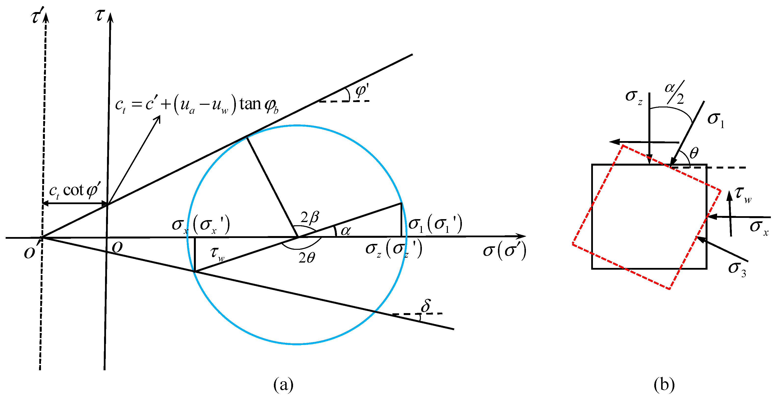
φb related to matric suction, and proposed a shear strength theory of two independent stress state variables for calculating the shear strength of unsaturated soil. As shown in
Figure 1, in the three-dimensional space of two stress variables and shear stress, the shear strength envelope is a plane. The expression of shear strength is given by:
where
σ is the total normal stress;
ua and
uw are the pore air pressure and the pore water pressure; (
σ −
ua) represents the net normal stress on the failure plane;
φ’ is the effective internal friction angle;
c’ is the effective cohesion; (
ua −
uw) represents the matric suction;
φb is matric suction angle, which indicates the rate of increase in the soil strength with respect to an increase in matric suction.
Subsequent studies [
36,
37] found that the
ϕb is not a fixed value. With the change of matric suction,
φb will take different values. Based on the microscopic analysis of unsaturated soil, Vanapalli et al. [
38] suggested that the SWCC model be used to correlate the relationship between
ϕb and volumetric water content of soil, which has the following form:
where
θ is the volumetric water content;
θr is the residual volumetric water content; and
θs is the saturated volumetric water content. Using the SWCC model proposed by Van Genuchten [
39], the matric suction angle corresponding to different matric suction can be obtained from the following formula:
where
α and
n are SWCC fitting parameters; parameter
α is approximate to the inverse of air entry suction; parameter
n reflects the pore size distribution.
Through the above analysis, when the value of matric suction is determined, the shear strength provided by the matric suction can be calculated. The intercept of the shear strength envelope in the corresponding net stress and shear stress plane coordinate system is the sum of the shear strength provided by the effective cohesion and matric suction, as shown in
Figure 1. In the subsequent calculation, we will express the contribution of matric suction to shear strength through total cohesion:
3. Lateral Pressure Coefficient and Shear Stress Coefficient
Terzaghi [
40] defines the phenomenon of earth pressure transfer from the yield zone to the adjacent static zone as a soil arching effect, and the existence of the soil arching effect changes the distribution of the earth pressure. The basic idea of calculating the earth pressure by soil arching effect is to obtain the active lateral earth pressure coefficient by assuming the geometric shape of the principal stress arch, and then solve the average vertical pressure and earth pressure of the soil layer according to the differential element force balance equation. In the calculation of the lateral earth pressure, the circular earth arch is widely used and the earth pressure distribution is in good agreement with the test results [
18,
19,
41]. However, few studies have considered the influence of adjacent underground buildings on the soil arch.
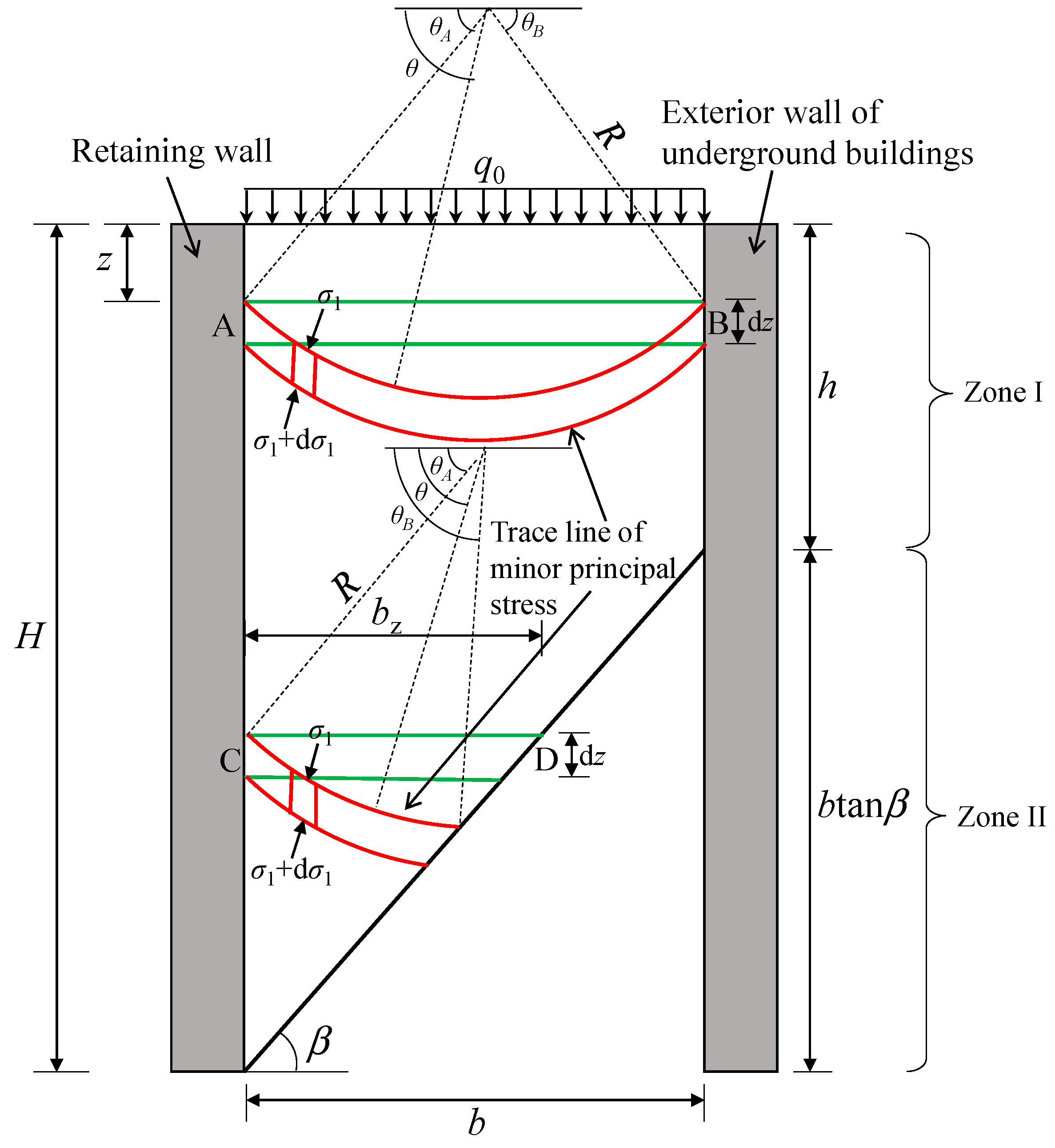
As shown in
Figure 2, in the case of narrow backfill, assuming that the backs of two rigid walls are vertical, and the backfill surface is horizontal, it is considered that there is an overload q0 on the surface of the backfill, and the backfill of the wall is in an unsaturated state. Suppose the wall height is
H, the soil weight is
γ, the soil cohesion is
c’, the soil friction angle is
φ’, the friction angle between the retaining wall and the soil is
δ1, and the friction between the existing building and the soil is angle is
δ2. The active slip surface intersects with the adjacent underground buildings to form a trapezoidal soil wedge, the Coulomb slip surface is assumed to be the slip surface under this working condition, and the inclination angle
β of the Coulomb-type slip surface passing through the wall heel is:
Different lateral earth pressure coefficients and interlayer shear stress coefficients will be obtained when the soil arching effect is analyzed in the upper rectangular region (zone I) and the lower triangular region (zone II). In this section, the lateral earth pressure coefficient and the interlayer shear stress coefficient of each region are solved first, and the influence of the wall soil friction angle on them is discussed. Then, in the next section, the distribution of earth pressure, resultant force and their action points in each region are solved according to the horizontal thin layer element method.
Considering the total cohesion of unsaturated soils, the coordinate system
σ’
oτ is obtained by translating the coordinate system
σoτ to the left by
ctcot
ϕ’, as shown in
Figure 3. Next, the lateral earth pressure coefficient and interlayer shear stress coefficient will be calculated by analyzing the soil arching effect in different areas.
Zone I:
From the stress Mohr’s circle in
Figure 3, the angles
θA and
θB between the large principal stress and the horizontal direction at points A and B in
Figure 2 can be expressed as:
where
δ1 and
δ2 are the interface friction angle of the moving wall and the fixed wall.
The width of the horizontal thin layer element in zone I can be calculated as:
where
R is the radius of circular soil arch.
In the new coordinate system, the horizontal stress, vertical stress and shear stress at any point in the soil arch can be expressed as:
where
σ’
1 is the major principal stress of the new coordinate system;
Ka is the Rankine active earth pressure coefficient, which can be calculated by
.
Handy [
17] and Paik [
18] defined the lateral active earth pressure coefficient as the ratio of the horizontal stress behind the retaining wall to the average value of the vertical stress on the soil arch trajectory. Similarly, we define the interlayer shear stress coefficient as the ratio of the average shear stress on the soil arch trajectory to the average vertical stress on the soil arch trajectory.
The average shear stress and the average vertical stress on the soil arch trajectory can be obtained by the integral method:
The horizontal reaction force of the retaining wall in the new coordinate system can be expressed as:
Therefore, in the new coordinate system, the lateral active earth pressure coefficient and interlayer shear stress coefficient are:
Zone II:
The deflection angle of point C has the same expression as that of point A. Considering the deflection of the principal stress at the sliding surface,
θC and
θD is obtained, as follows:
The width of the horizontal element in zone II and the radius of the soil arch conform to the following relationship:
Referring to Equations (12)–(14), the average vertical stress, average shear stress and horizontal reaction force of the retaining wall in zone II can be expressed as:
Then, the lateral pressure coefficient and interlayer shear stress coefficient of zone II in the new coordinate system can be expressed as:
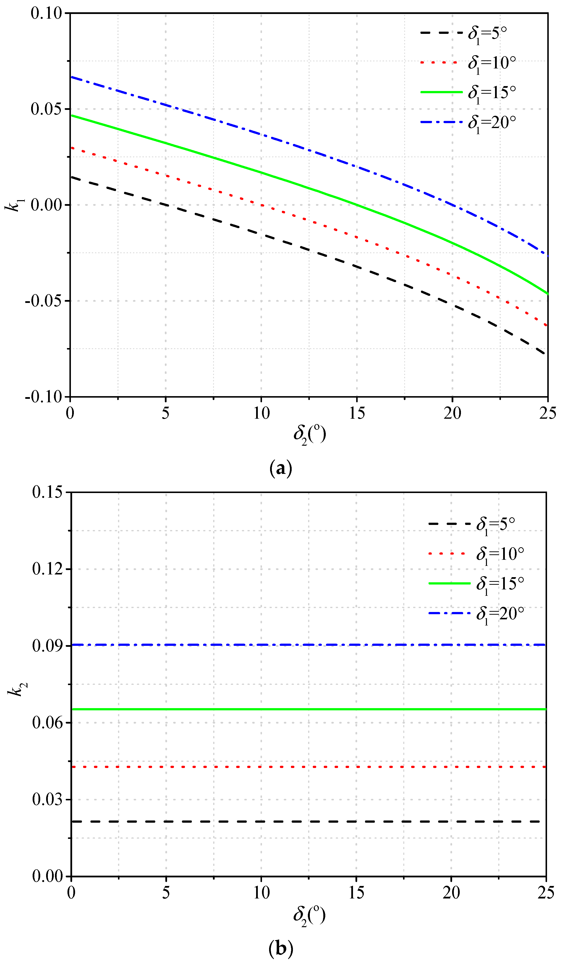
Figure 4 shows the relationship between the interlayer shear stress coefficients (
k1 and
k2) and the interface friction angle of the fixed wall–soil
δ2 under different values of the interface friction angle of the moving wall–soil
δ1. The curves in the figures are obtained from Equations (16) and (24). As shown in the
Figure 4a, the increase of
δ1,
k1 increases obviously, but decreases with the increase of
δ2. Moreover, from
Figure 4b,
k2 increases with the increase of
δ1, but does not change with the increase of
δ2. This is because the soil arch in zone II is not formed to the fixed wall. Additionally, when
δ1 =
δ2,
k1 = 0. As
δ2 continues to increase,
k1 will take a negative value, and the direction of the interlayer shear stress will change.
4. Derivation of Active Earth Pressure Formula
For unsaturated backfills, the tension cracks on the backfill surface cannot be ignored due to matric suction. Combining Equation (9) and the transformation relationship between the two coordinate systems, at the critical depth (
z =
hc), the following relationship is given:
Rewriting the above equation, the tension crack depth can be expressed as:
In Equation (26), when hc < 0, take hc = 0.
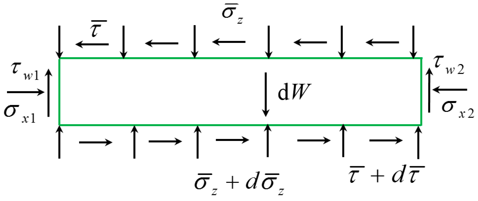
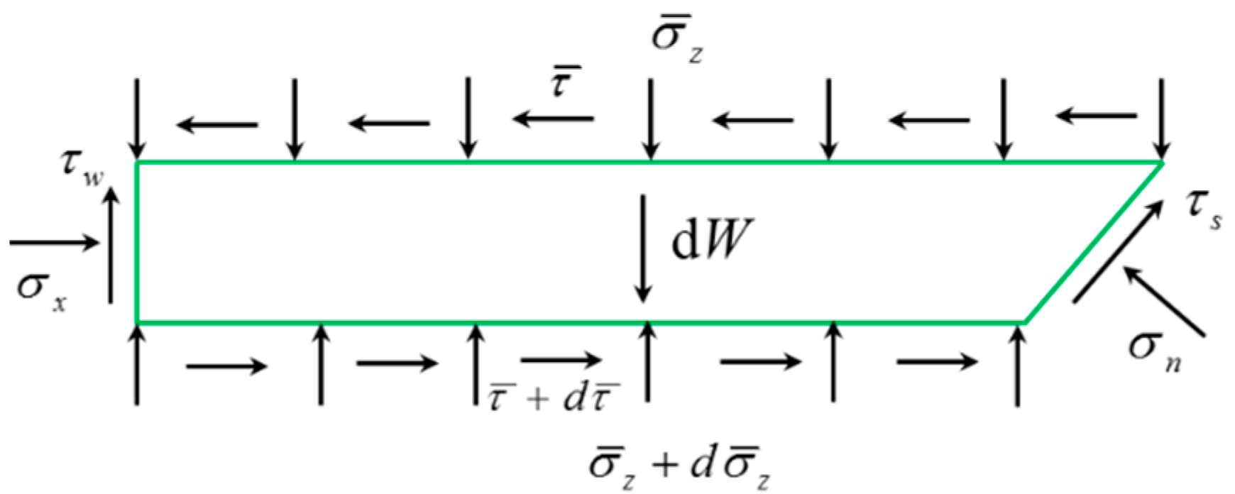
Zone I:
Carry out force balance analysis for rectangular thin layer element, as shown in
Figure 5, in which
σx1 and
σx2 are the horizontal reaction force of the retaining wall and fixed wall;
τw1 and
τw2 are the interface shear stress of the retaining wall and fixed wall;
and
are the average vertical stress acting on the upper surface and lower surface;
and
are the average interlayer shear stress acting on the upper surface and lower surface; d
W is the self-weight of thin layer element.
The force equilibrium equations in the vertical and horizontal directions are established as:
where
The adhesive force of wall and soil can be considered as the same as the friction force, which is given by:
Neglecting the second-order terms, the first-order differential equation can be obtained by solving Equations (27) and (28):
where
By integrating Equation (30), the average vertical stress can be solved as:
Substituting the boundary conditions (
,
) into Equation (33),
C1 is obtained as follows:
Zone II:
As shown in
Figure 6, according to the equilibrium conditions of stresses acting on the trapezoidal thin layer element, the two equations are expressed as:
in which
where
σn and
τs are the normal stress and shear stress on the slip surface.
Combining Equations (35) and (36), a differential equation is obtained as:
where
Integrating Equation (38) can be solved as
By substituting the boundary value
,
,
C2 is obtained, as follows:
Therefore, the distribution of the horizontal active earth pressure is obtained as:
The resultant force of the horizontal active earth pressure and the total overturning moment of the retaining wall can be expressed, respectively, as
It should be noted that a special working condition may also occur. When
h <
hc, there will be no zone I. In this case, the boundary conditions (
,
) are substituted into Equation (40), and
C2 is obtained as follows:
Then, the horizontal active earth pressure, resultant force of horizontal active earth pressure and the total overturning moment of the retaining wall can be expressed, respectively, as
The distance from the location of the resultant of the active earth pressure to the heel of the wall, denoted as
Ha, can be easily derived as the ratio of
M to
Ex:
6. Parametric Study
In this section, a parametric study was performed to analyze the effective internal friction angle φ’, surcharge pressure q0, interface friction angle δ, effective cohesion c’, matric suction (ua − uw), and width-height ratio of backfill b/H on the distribution of the horizontal active earth pressure. In the analysis, these parameters were fixed: γ = 18 kN/m3, α = 0.02 kPa−1, n = 3 and H = 10 m. Other parameters for analysis can be found in the analysis figures. In addition, the interface friction angle δ1 of the moving wall–soil and the interface friction angle δ2 of the fixed wall–soil are equal, that is, δ1 = δ2 = δ.
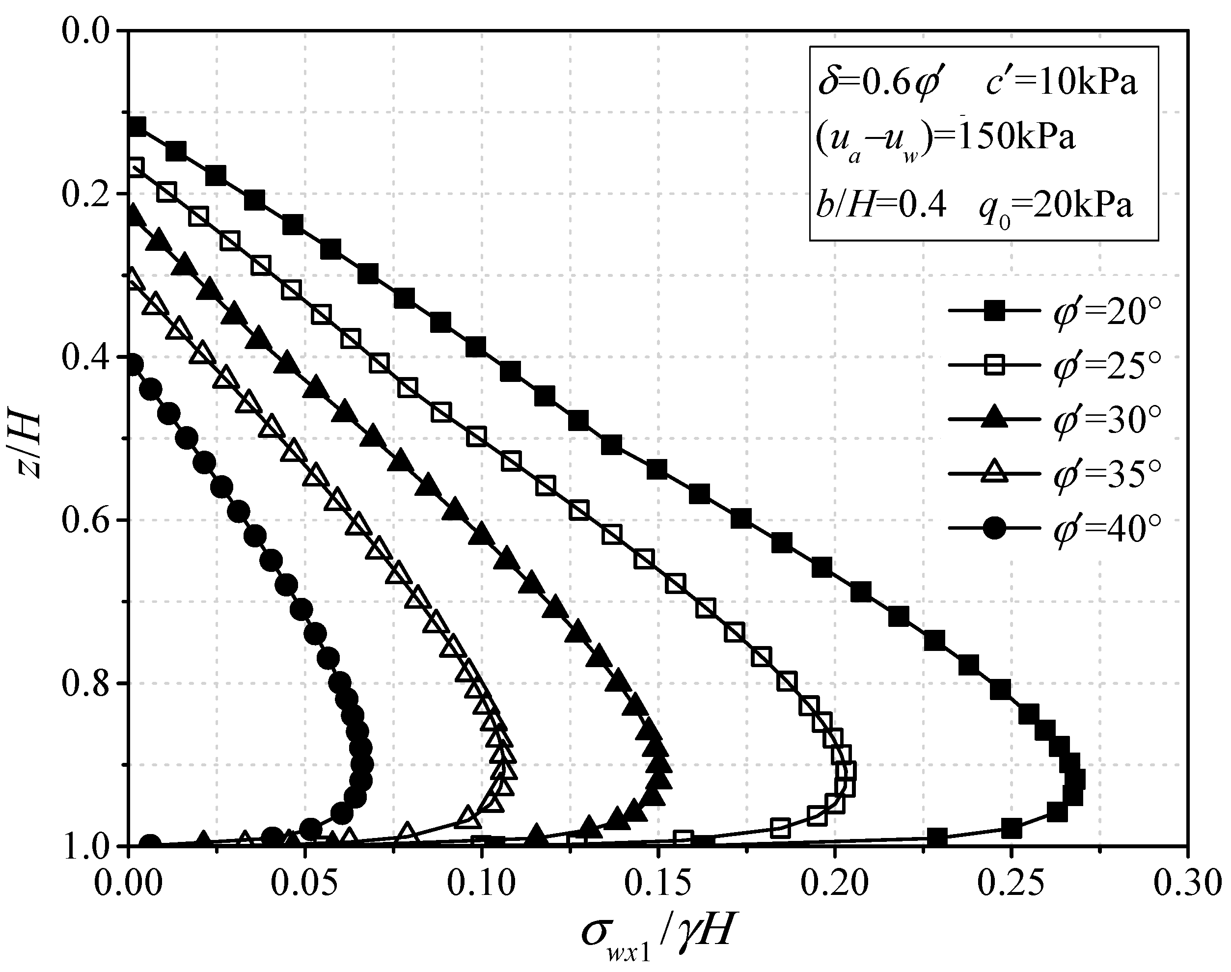
Figure 8 depicts the normalized horizontal active earth pressure (
σx/
γH) along the normalized height (
z/
H) for the various effective internal friction angle
φ’. To investigate the effect of the effective internal friction angle on the horizontal active earth pressure against the retaining structure, different values of
φ’ (i.e.,
φ’ = 20°, 25°, 30°, 35° and 40°) were used. From
Figure 8, it is obvious that the horizontal earth pressure first increases and then decreases along the depth, showing a nonlinear “drum” distribution, reaching a peak above the wall bottom. With the effective internal friction angle increases, the active earth pressure acting on the retaining wall at each depth decreases significantly, and the area where the earth pressure is zero gradually increases, indicating that the depth of the tension crack also increases with the increase in the effective internal friction angle.
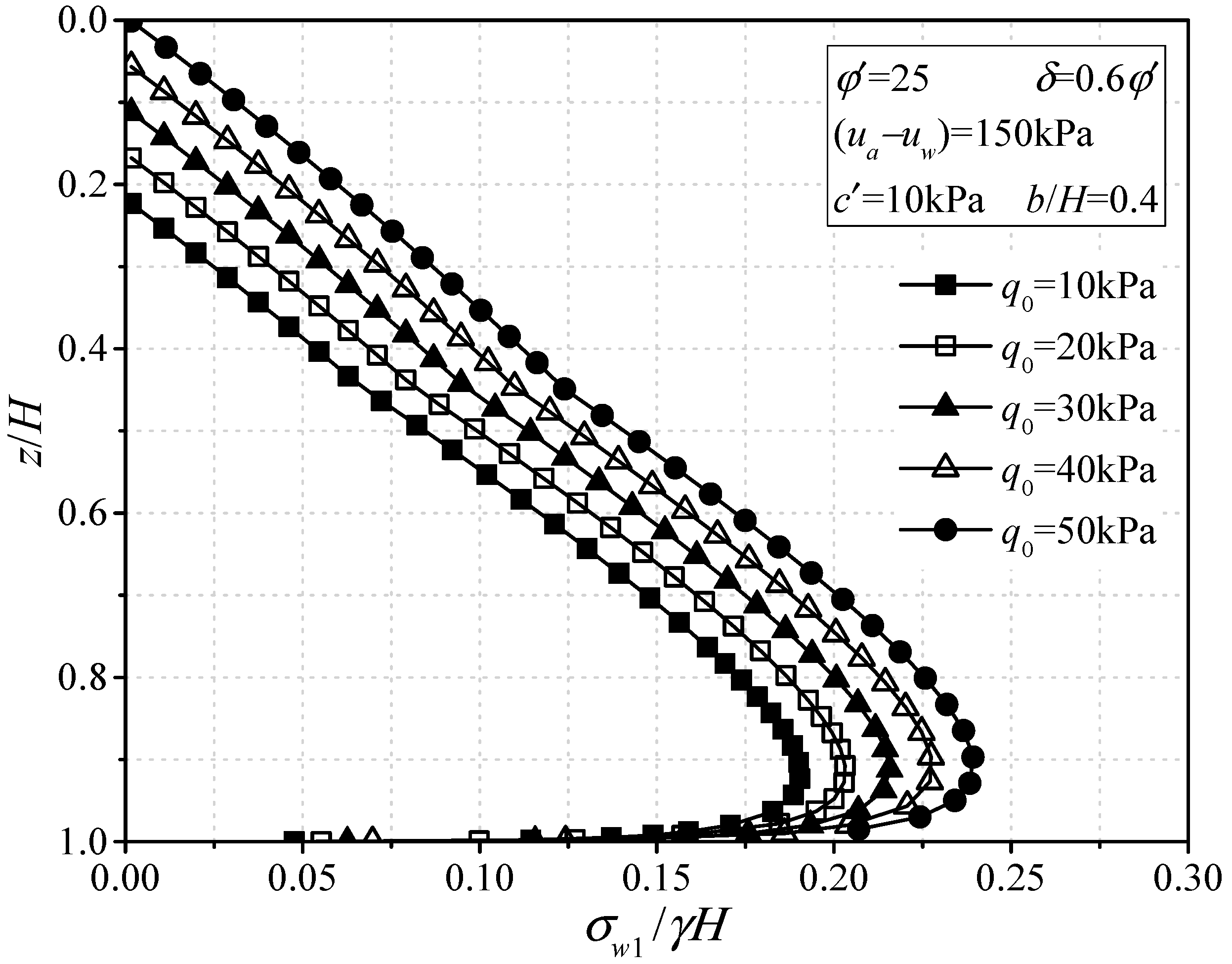
Figure 9 shows the normalized horizontal active earth pressure (
σx/
γH) along the normalized height (
z/
H) for different values of the surcharge pressure
q0. Herein, the aim is to discuss the effect of the surcharge pressure on the horizontal active earth pressure against the retaining structure, and thus different constant values of
q0 (i.e.,
q0 = 10 kPa, 20 kPa, 30 kPa, 40 kPa and 50 kPa) were used.
Figure 9 shows that the horizontal active earth pressure increases significantly with the increase in surcharge pressure applied on the backfill surface, whereas the shape of the horizontal active earth pressure distribution remains unchanged. Moreover, the depth of the tension crack decreases with the increase in the surcharge pressure, and when values of
q0 are large enough, the tension crack will not form.
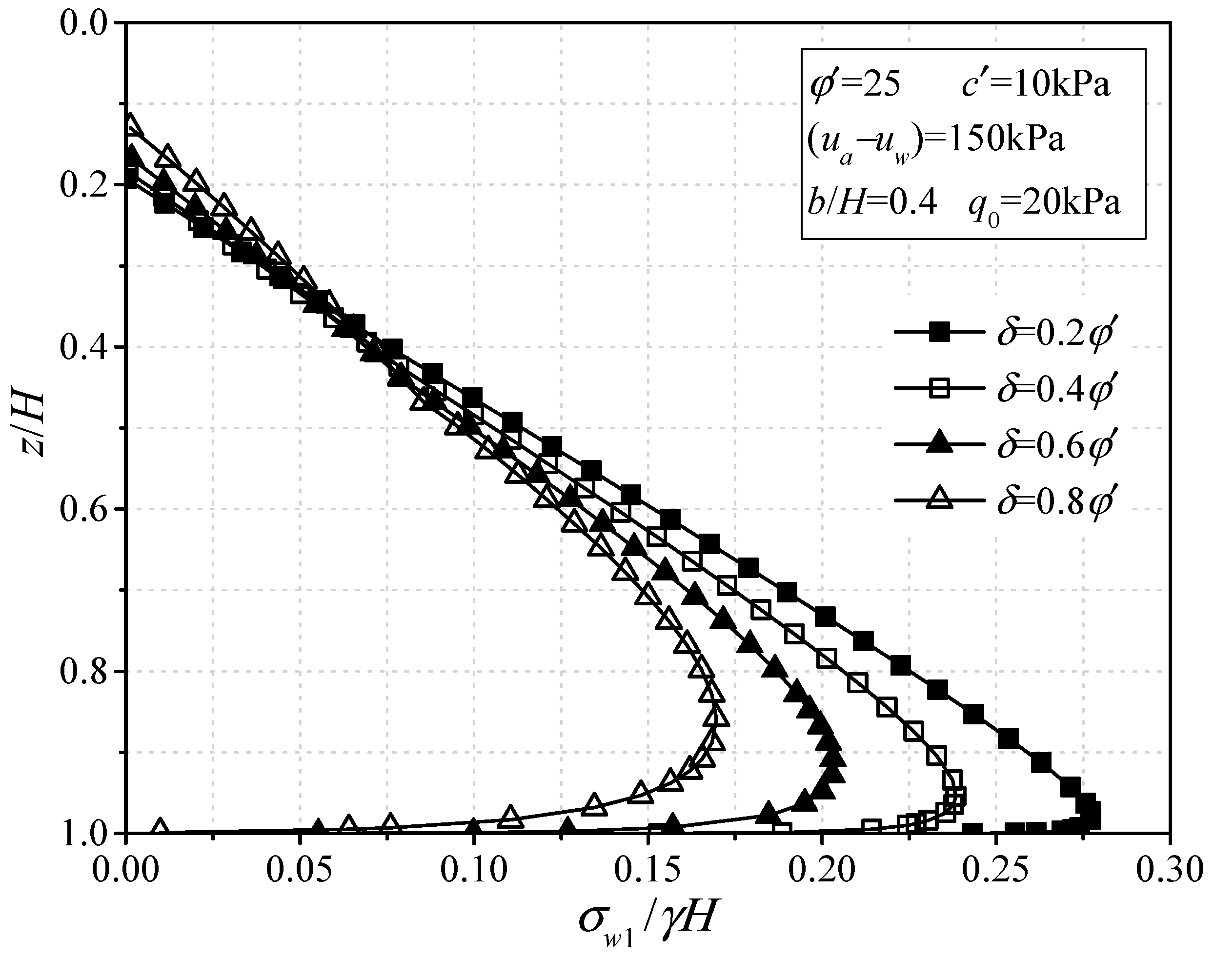
Figure 10 illustrates the normalized horizontal active pressure (
σx/
γH) along the normalized height (
z/
H) for the various interface friction angle
δ. To discuss the effect of interface friction angle on the horizontal active earth pressure against the retaining structure, different values of
δ varying from 0.2
φ’ to 0.8
φ’ were used here. As shown in
Figure 10, with the increase in the interface friction angle, the horizontal active earth pressure in the upper part of the retaining wall increases slightly, while the horizontal active earth pressure in the lower part decreases obviously. Furthermore, the action point of the horizontal earth pressure resultant force has a tendency to move upward with the increase in interface friction angle.
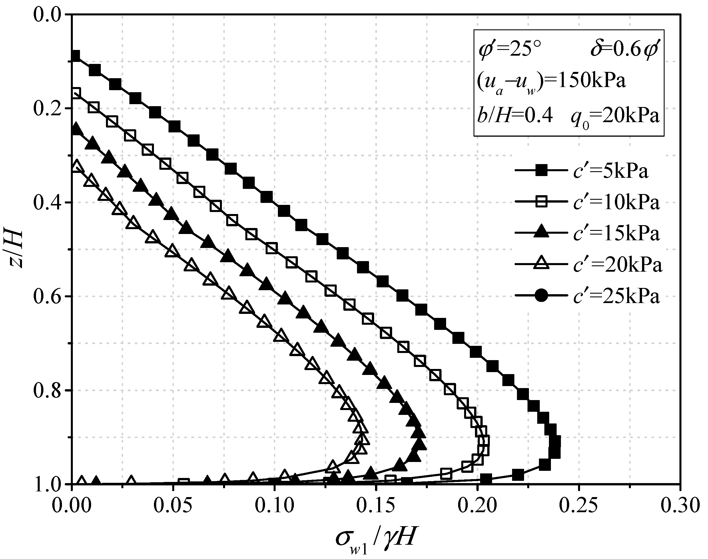
Figure 11 shows the normalized horizontal active earth pressure (
σx/
γH) along the normalized height (
z/
H) for the various values of soil effective cohesion
c’. To analyze the impact of the backfill inclination angle on the horizontal active earth pressure against the retaining wall, different values of
c’ (i.e.,
c’ = 5 kPa, 10 kPa, 15 kPa, 20 kPa and 25 kPa) were used.
Figure 11 shows a pronounced decrease in the horizontal active earth pressure against the rigid retaining wall with the increasing value of
c’, and the depth of the tension crack in soil increases correspondingly. From the earth pressure distribution curves, with the increase in the effective cohesion of the soil, the earth pressure distribution curves gradually shift to the left axis.
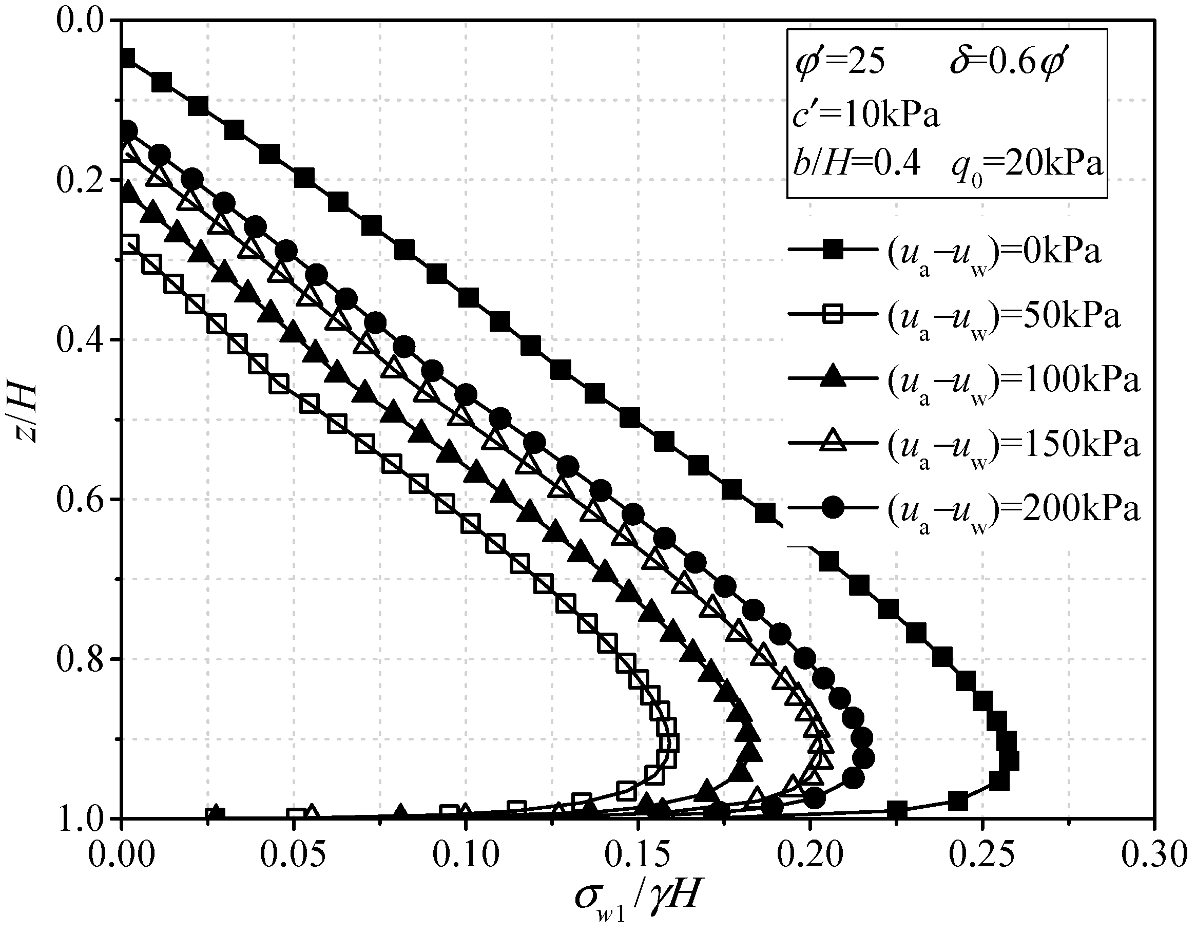
Figure 12 depicts the normalized horizontal active earth pressure distribution (
σx/
γH) along the normalized height (
z/
H) for various matric suction (
ua −
uw). To study the effect of the matric suction (
ua −
uw) on the horizontal active earth pressure against the retaining wall, various values of (
ua −
uw) varying from 0 kPa to 200 kPa were used. From
Figure 11, with the increase in matric suction, the horizontal active earth pressure first decreases rapidly and then increases gradually, and the depth of the tension crack first increases obviously and then decreases, while the shape of the horizontal active earth pressure distribution remains unchanged. The reason is that the total cohesion increases first and then decreases with the increase in matric suction, and this is consistent with the conclusion given by Song [
42]. the horizontal active earth pressure reaches its minimum value at the matric suction equaling 50 kPa; this is because the matric suction takes the air entry pressure (approximately equal to the reciprocal of parameter α), and the apparent cohesion provided by the matric suction is the largest.
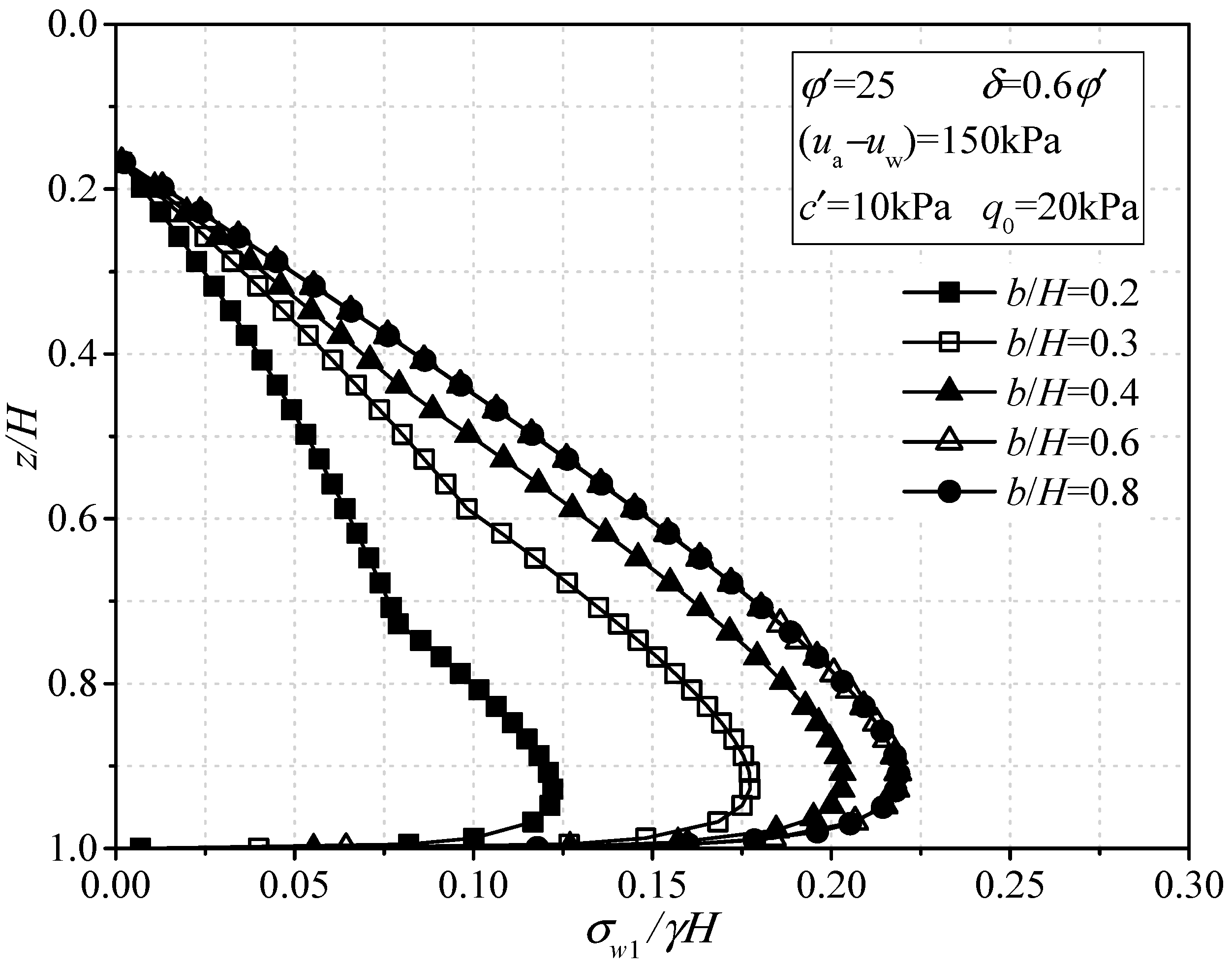
The normalized horizontal active earth pressure distribution (
σx/
γH) along the normalized height (
z/
H) for different width-height ratio of backfill
b/H is shown in
Figure 13. In order to study the effect of the width of backfill on the horizontal active earth pressure against the retaining wall, various values of
b/
H (i.e.,
b/
H = 0.2, 0.3, 0.4, 0.6, and 0.8) were employed. As shown in
Figure 13, the magnitude of the horizontal active earth pressure decreases with the decrease in the
b/
H value, and the attenuation becomes clearer when the
b/
H value is smaller. When the width of backfill reaches a certain value, the horizontal active earth pressure remains unchanged with the increase in the
b/
H value. This is because the backfill with a sufficient width allows the slip surface to fully develop.


