

Green Technology Solution for Small-World Communication Using Plastic Optical Fiber (POF) and Light Emitting Diode (LED)—Design and Application

Abstract
:1. Introduction
2. Materials
Polymethyl Methacrylate (PMMA)
3. Fabrication Technique
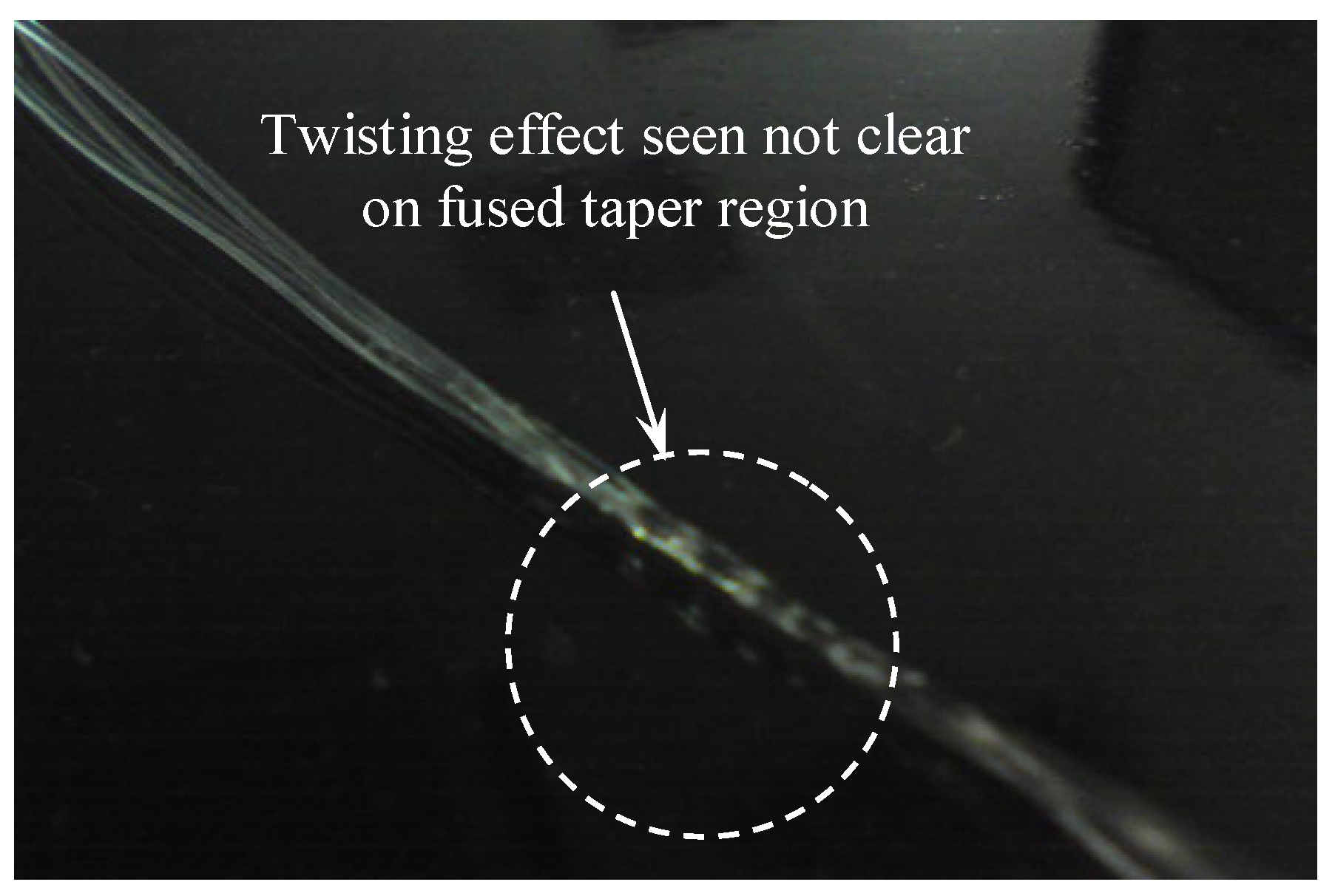
3.1. Low-Cost Fused Taper (LFT)
3.2. First Generation/Type 1 (G1)
3.3. Second Generation/Type 2 (G2)
3.4. Comparison
4. POF Devices
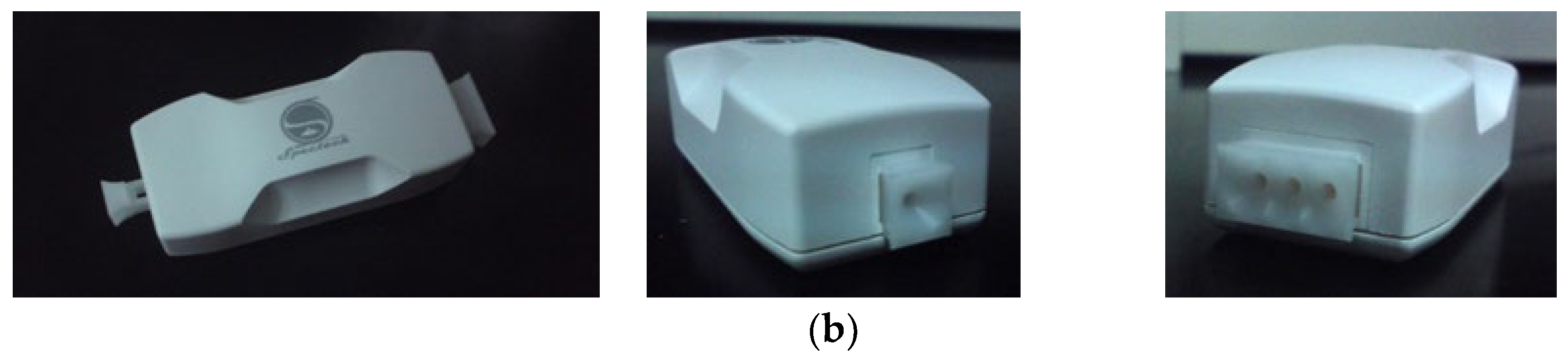
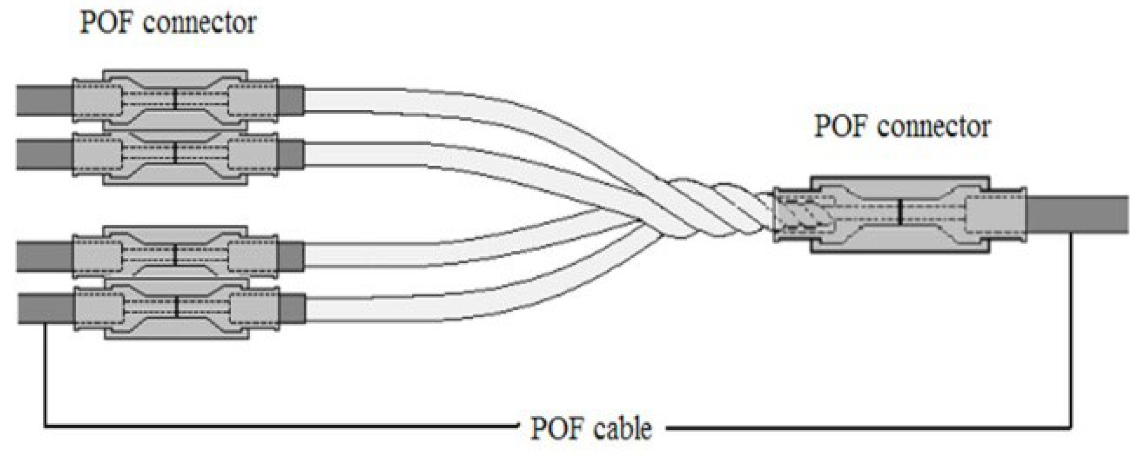
4.1. Splitter
4.2. Demultiplexer
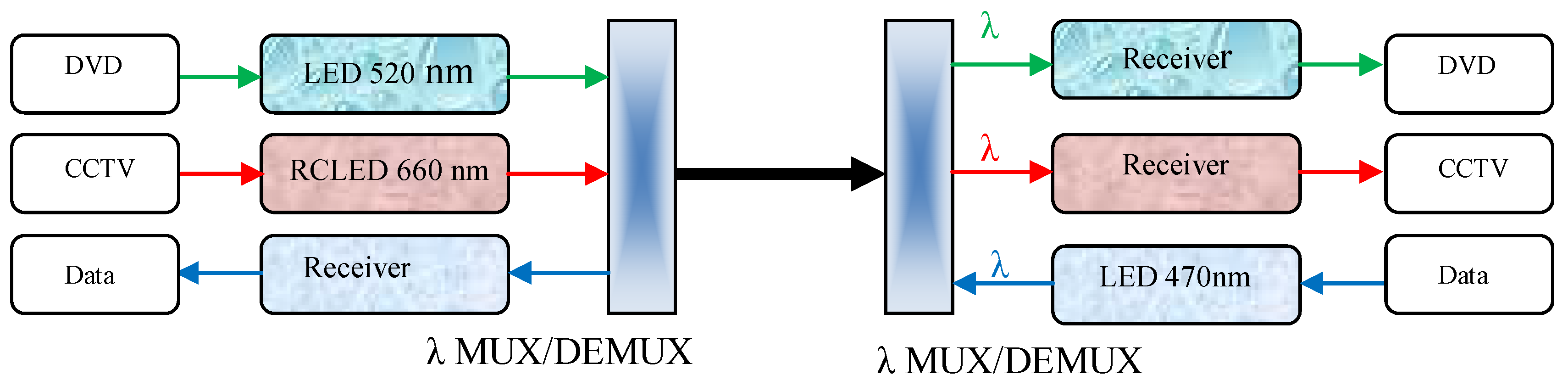
5. Configuration
WDM-POF Network
- Fiber type: 950 μm PMMA SI-POF.
- Length: 10–45 m.
- Transmission Rate: 1 × analog video, DVD signal (2.8 Mbit/s); 200 Mbps Ethernet signal; and 100 Mbit/s.
- Transmitter: 520 nm LED; 660 nm RCLED; & 470 nm LED.
- Receiver: Analog video Luceat 950 μm with BNC; DiMoto DM-USB connector; DieMount Optospider POF (simpleks) without connector.
- Demultiplexer: 1 × 3 LFT Splitter with Roscolux filter (3 wavelengths) Green (#89: Moss Green).
- Red (#4690: CalColor 90 Red); and Blue (#69: Brilliant Blue).
6. Application
6.1. Home Networking over POF
6.2. In-Vehicle Network
7. Discussion
8. Conclusions
Author Contributions
Funding
Institutional Review Board Statement
Informed Consent Statement
Data Availability Statement
Acknowledgments
Conflicts of Interest
References
- Liem, A.T.; Hwang, I.; Nikoukar, A.; Yang, C.Z.; Ab-Rahman, M.S.; Lu, C. Software-Defined Time-Shifted IPTV Architecture for Locality-Awareness TWDM-PON. Opt. Int. J. Light Electron Opt. 2020, 207, 164179. [Google Scholar]
- Ganesan, E.; Hwang, I.; Liem, A.T.; Ab-Rahman, M.S. 5G-Enabled Tactile Internet Resource Provision via Software-Defined Optical Access Networks (SDOANs). Photonics 2021, 8, 140. [Google Scholar] [CrossRef]
- Posinasetti, N.R. Sustainable Manufacturing: Principles, Applications and Directions. Efficient Manufacturing. In Proceedings of the 28th National Convention of Production Engineers, Institution of Engineers, Jaipur, India, 21 May 2013; Volume 28. [Google Scholar]
- Nagle, K. What Is Green Manufacturing, and Why Does It Matter? Evocon. 2022. Available online: https://evocon.com/articles/what-is-green-manufacturing-and-why-does-it-matter (accessed on 10 August 2022).
- Ghillino, E.; Richards, D.; Mena, P.V.; Hyuga, S.; Nakai, M.; Kagami, M.; Robert Scarmozzino, S. Using system simulation to evaluate design choices for automotive ethernet over plastic optical fiber. In Metro and Data Center Optical Networks and Short-Reach Links; SPIE: San Francisco, CA, USA, 2018; Volume 10560, pp. 133–141. [Google Scholar]
- Xiaofeng, S.; Zhongxin, W.; Yuan, Z.; Li, P.; Bo, H.; Zhengping, Z. Optimal Design of High-speed 650 nm Optical Fiber Communication System. In Proceedings of the 2019 IEEE International Conference on Power, Intelligent Computing and Systems (ICPICS), Shenyang, China, 12–14 July 2019; pp. 185–188. [Google Scholar]
- Ab-Rahman, M.S.; Supian, L.S.; Safnal, H.G.; Harun, M.H.; Jumari, K. OSNR Performance on Hand-Made Demultiplexer Using Thin-Film Filter And Splitter In Wdm-Pof Network Design For Short-Haul Communication System Applications. J. Appl. Sci. Res. 2012, 8, 1186–1190. [Google Scholar]
- Ali, A.; Zhang, C.; Hassnain, S.A.; Lyu, W.; Tehseen, R. Underwater Wireless-to-Plastic Optical Fiber Communication Systems with a Passive Front End. In Proceedings of the 2019 18th International Conference on Optical Communications and Networks (ICOCN), Huangshan, China, 5–8 August 2019; pp. 1–3. [Google Scholar] [CrossRef]
- Mohammed, A.S.; Adnan, S.A.; Ali, M.A.A.; Al-Azzawi, W.K. Underwater wireless optical communications links: Perspectives, challenges and recent trends. J. Opt. Commun. 2022. [Google Scholar] [CrossRef]
- Ali, A.; Tehseen, R.; Mithilesh, M.K.; Hassnain, S.A.; Zhang, Z.; Zhang, C.; Mehdi, S.R.; Mahmood, A.; Xu, J. Blue Laser Diode-Based Remote Solid-State Lighting Using Plastic Optical Fiber and Phosphor Film for a Hazardous Environment. ECS J. Solid State Sci. Technol. 2021, 10, 016001. [Google Scholar] [CrossRef]
- López, A.; Losada, M.Á.; Mateo, J. Simulation Framework for POF-Based Communication Systems. In Proceedings of the 17th International Conference on Transparent Optical Networks (ICTON), Budapest, Hungary, 5–9 July 2015; pp. 1–4. [Google Scholar] [CrossRef]
- Ehsan, A.A.; Shaari, S.; Rahman, M.K.A. 1 X 2 Y-Branch Plastic Optical Fiber Waveguide. Coupler For Optical Access-Card System. In Proceedings of the Electromagnetics Research Symposium (PIERS), Beijing, China, 23–27 March 2009; pp. 1079–1082. [Google Scholar]
- Ehsan, A.A.; Shaari, S.; Rahman, M.K.A. Design and fabrication of an acrylic-based 1 × 2 POF coupler using CNC Machining. In Proceedings of the International Conference on Semiconductor Electronics (ICSE 2008), Johar Bahru, Johar, Malaysia, 25–27 November 2008; IEEE: New York, NY, USA, 2008; pp. 340–344. [Google Scholar]
- Ab-Rahman, M.S.; Guna, H.; Arsad, N. Effect of the Surface Roughness on Cross Sectional Properties of 1 × 3 Polymer Optical Fiber-based Splitter. J. Phys. Conf. Ser. 2021, 1748, 062008. [Google Scholar] [CrossRef]
- Farshad, N.K.; Mohammad, S.A. Optimizing in-vehicle Multiplexed Network Using WDM Over POF. In Applied Mechanics and Materials; Trans Tech Publications Ltd.: Wollerau, Switzerland, 2014; Volume 663, pp. 675–681. [Google Scholar]
- Zieamann, O.; Krauser, J.; Zamzow, P.E.; Daum, W. POF Handbook: Optical Short Range Transmission Systems, 2nd ed.; Springer: Berlin/Heidelberg, Germany, 2008. [Google Scholar]
- Imoto, K.; Maeda, M.; Kunugiyama, H.; Shiota, T. New biconically Tapered Fiber Star Coupler Fabricated by Indirect heating Method. J. Lightwave Technol. 1987, 5, 694–699. [Google Scholar] [CrossRef]
- Ab-Rahman, M.S.; Supian, L.S. Low Cost and Environmental Friendly Multimode Optical Coupler Fabrication using Circular Blocks Technique. OPTIK 2014, 125, 893–896. [Google Scholar] [CrossRef]
- Liu, J.; Cheng, T.-H.; Yeo Y-k Wang, Y.; Xu, Z.; Wang, D. Fused Biconical Tapered Technique Based Light Beam Coupling Between a Single Mode Fiber and a High Nonlinearly Photonic Crystal Fiber. In Proceedings of the Optical Fiber Communication Conference and National Fiber Optic Engineers Conference, San Diego, CA, USA, 22–26 March 2009; IEEE: Piscataway, NJ, USA, 2009; pp. 1–3. [Google Scholar]
- Ab-Rahman, M.S.; Supian, L.S.; Guna, H.; Mohammad, N.N.S.; Hwang, I.; Hipni, A. Fabrikasi Dan Pencirian Pencerai 3 × 3 Berasaskan Gentian Optik Polimer (POF) Dengan Teknik Pelakuran Berkos Rendah. Sains Malays. 2014, 43, 1743–1750. [Google Scholar]
- Kuzyk, M.G. Polymer Fiber Optics: Materials, Physics, and Applications; CRC Press: Carlsbad, CA, USA, 2007. [Google Scholar]
- Haupt, M.; Fischer, U. Design and development of a MUX/DEMUX element for WDM communication over SI-POF. In Proceedings of the Electronics System-Integration Technology Conference (ESTC 2008), London, UK, 1–4 September 2008; IEEE: New York, NY, USA, 2008; pp. 1257–1262. [Google Scholar]
- Haupt, M.; Fischer, U.H.P. Design and Development of a Mux/Demux Element for WDM over POF. In Proceedings of the International Students and Young Scientists Workshop Photonics and Microsystems, Dresden, Germany, 8–10 July 2007. [Google Scholar]
- Ab-Rahman, M.S.; Khamene, F.N.; Guna, H. New Concept For Reducing Wire-Harness And Implementing Advanced Facilities for Non-Luxury Vehicles Via Application of POF. Appl. Mech. Mater. 2012, 165, 98–103. [Google Scholar] [CrossRef]


| Design Specification | Type 1 (G1) | Type 2 (G2) |
|---|---|---|
| Smallest diameter of tapered POF (cm) | 1 ± 0.1 cm | 1 ± 0.1 cm |
| Tapering length (cm) | 4.5–6 cm | 1.7–2 cm |
| Connector type | DNP | DNP |
| Length of fiber output (cm) | 3–4 cm | 1 ± 0.03 mm |
| Jacket type | PVC | PVC |
Publisher’s Note: MDPI stays neutral with regard to jurisdictional claims in published maps and institutional affiliations. |
© 2022 by the authors. Licensee MDPI, Basel, Switzerland. This article is an open access article distributed under the terms and conditions of the Creative Commons Attribution (CC BY) license (https://creativecommons.org/licenses/by/4.0/).
Share and Cite
Ab-Rahman, M.S.; Safnal, H.; Kaharudin, I.H.; Hwang, I.-S. Green Technology Solution for Small-World Communication Using Plastic Optical Fiber (POF) and Light Emitting Diode (LED)—Design and Application. Sustainability 2022, 14, 10894. https://doi.org/10.3390/su141710894
Ab-Rahman MS, Safnal H, Kaharudin IH, Hwang I-S. Green Technology Solution for Small-World Communication Using Plastic Optical Fiber (POF) and Light Emitting Diode (LED)—Design and Application. Sustainability. 2022; 14(17):10894. https://doi.org/10.3390/su141710894
Chicago/Turabian StyleAb-Rahman, Mohammad Syuhaimi, Hadiguna Safnal, Iszan Hana Kaharudin, and I-Shyan Hwang. 2022. "Green Technology Solution for Small-World Communication Using Plastic Optical Fiber (POF) and Light Emitting Diode (LED)—Design and Application" Sustainability 14, no. 17: 10894. https://doi.org/10.3390/su141710894