
UAV-Based High-Rise Buildings Earthwork Monitoring—A Case Study


Abstract
:1. Introduction
2. Theoretical Framework
2.1. Overview of Earthwork and UAV Roles in Earthwork
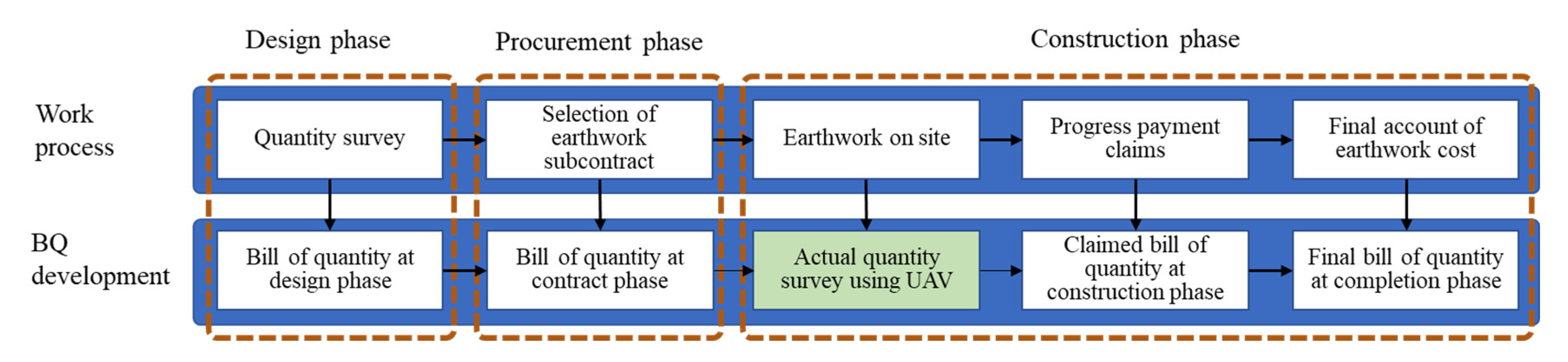
2.2. Earthwork Life Cycle
3. Study Area and Methodology
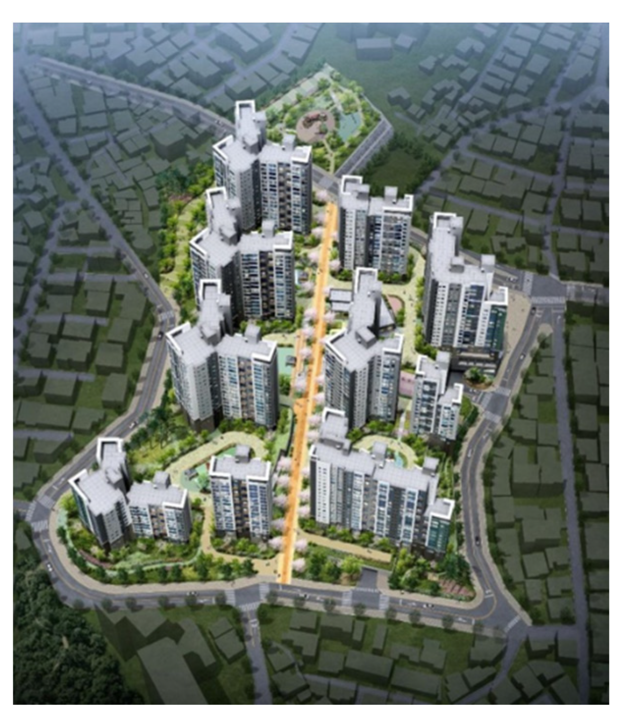
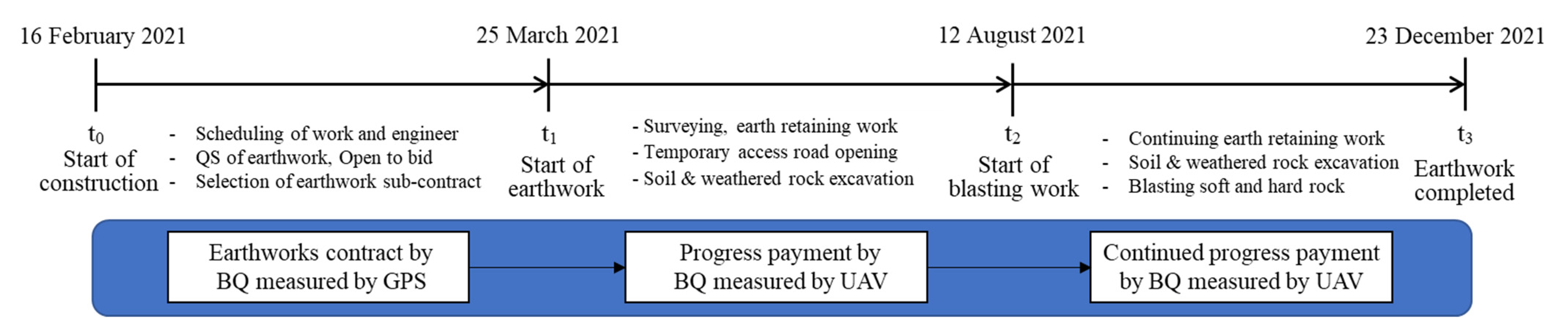
3.1. Study Area
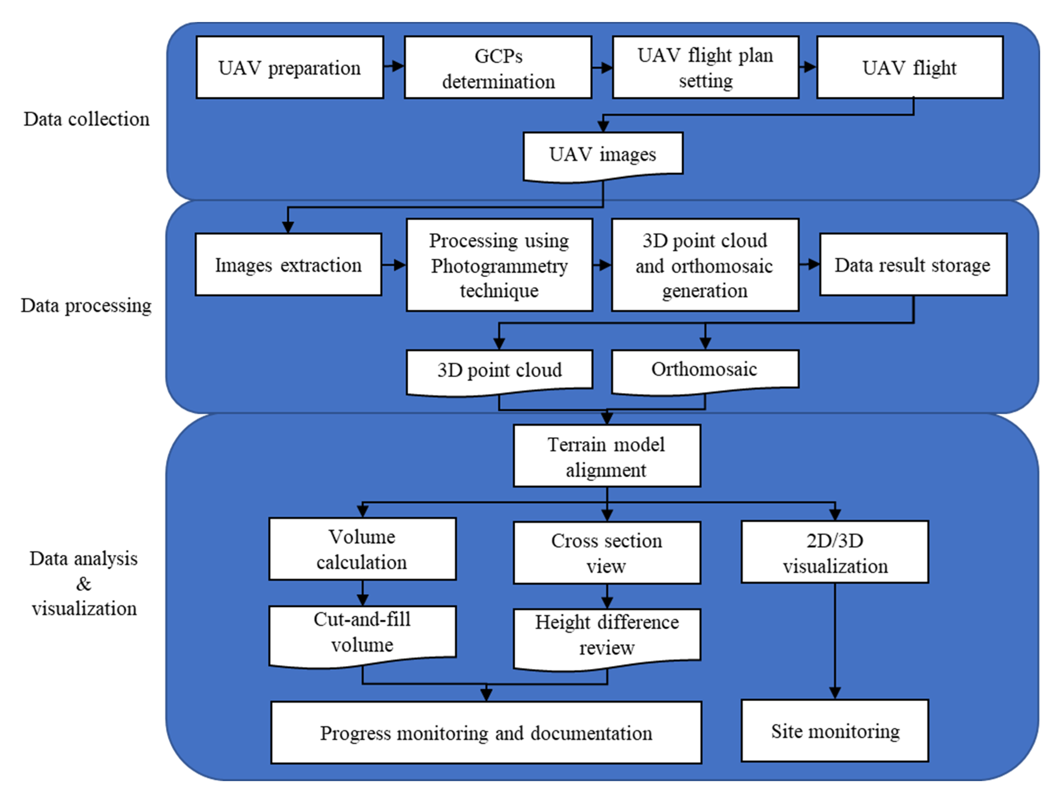
3.2. Methodology
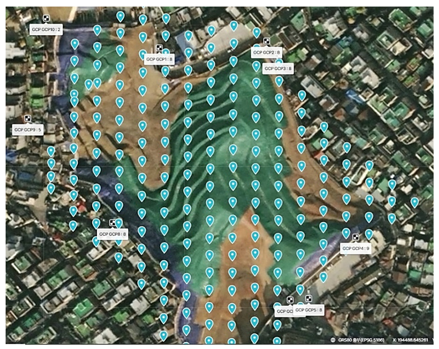
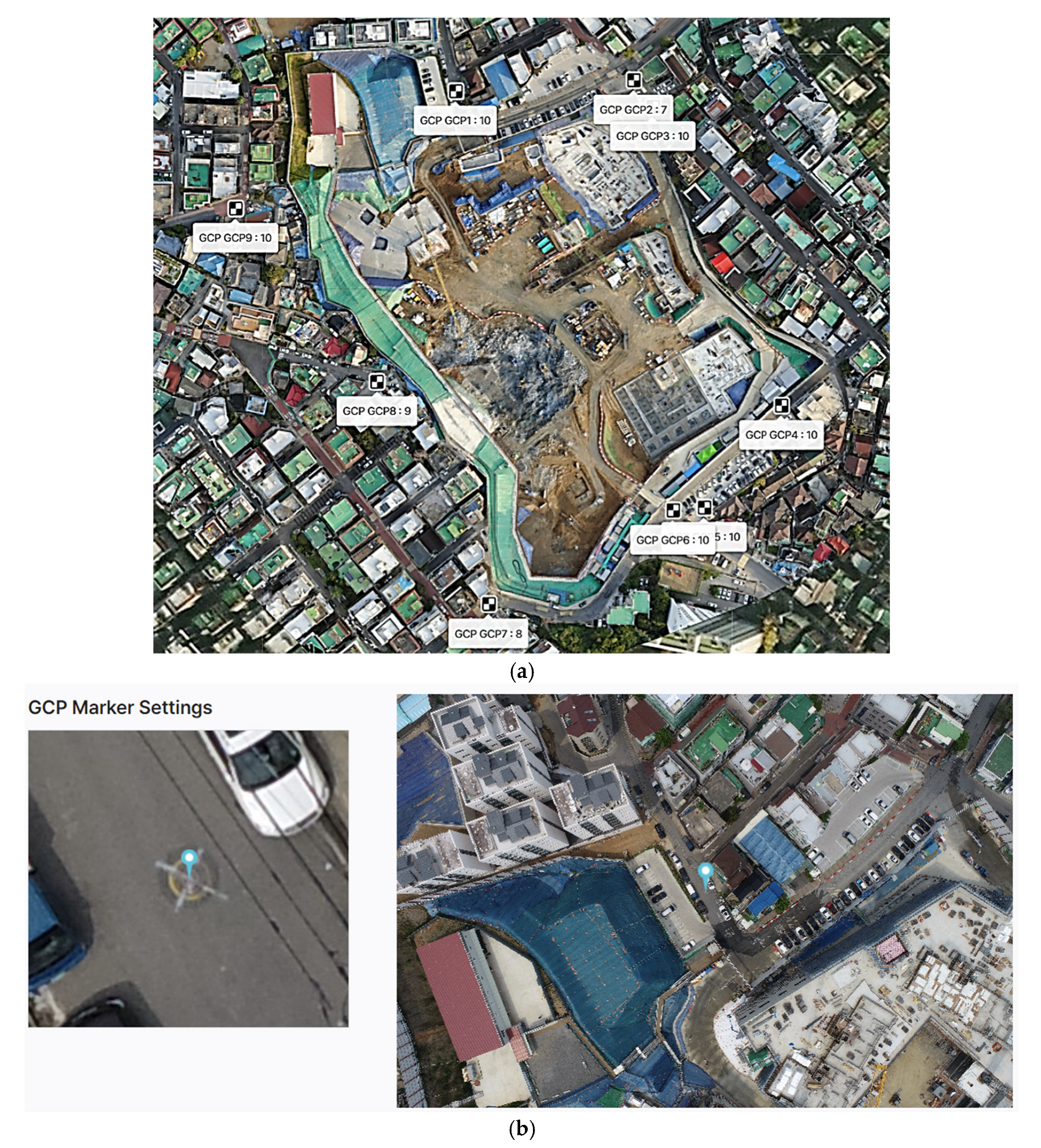
3.2.1. Data Collection
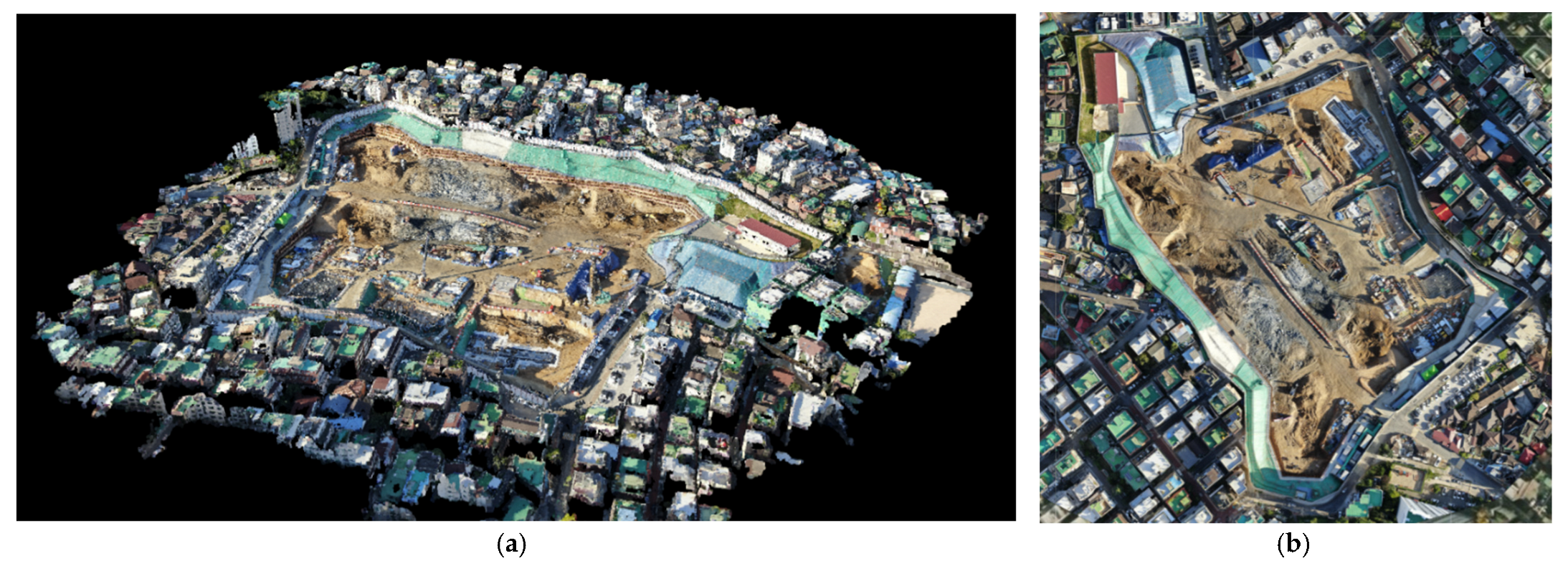
3.2.2. Data Processing
3.2.3. Data Analysis and Visualization
4. Results and Discussion
4.1. Volume Assessment
4.2. Cost Comparison of Computed Volume
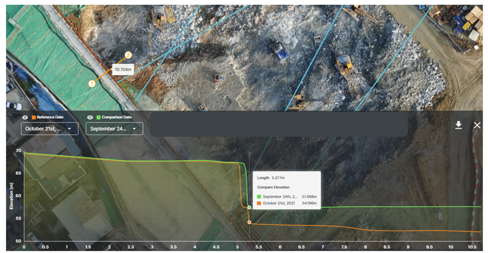
4.3. Height Difference and Slope Monitoring
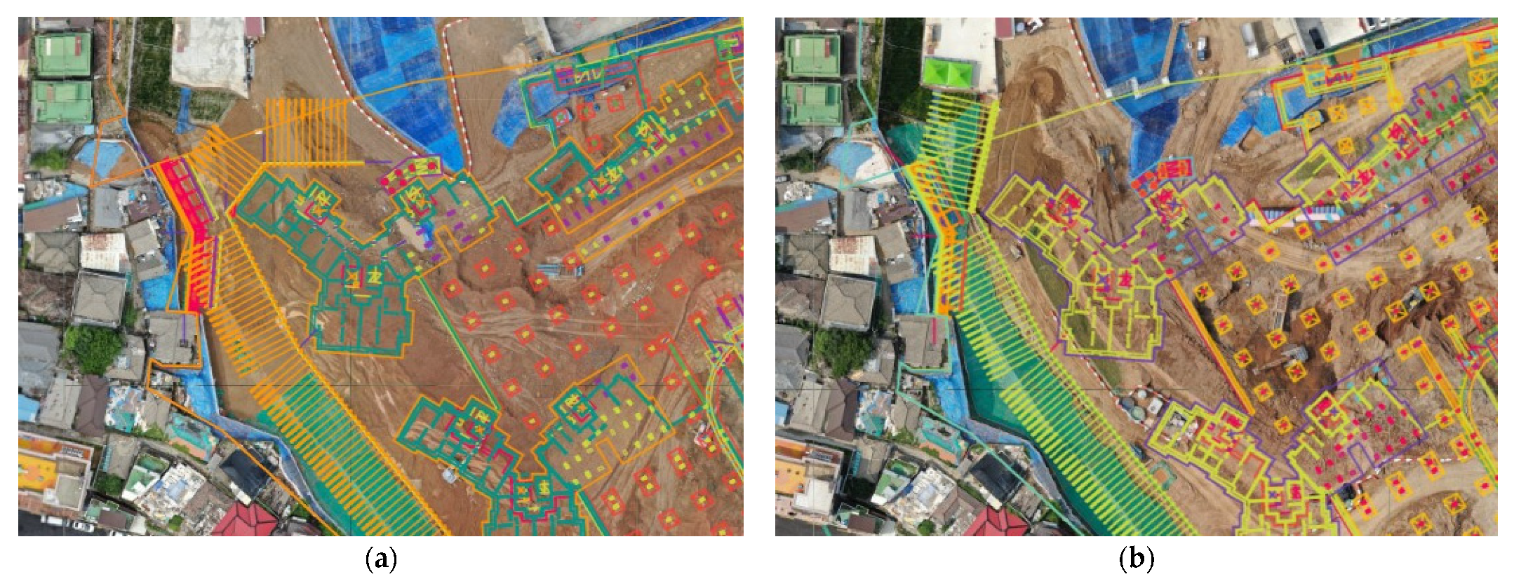
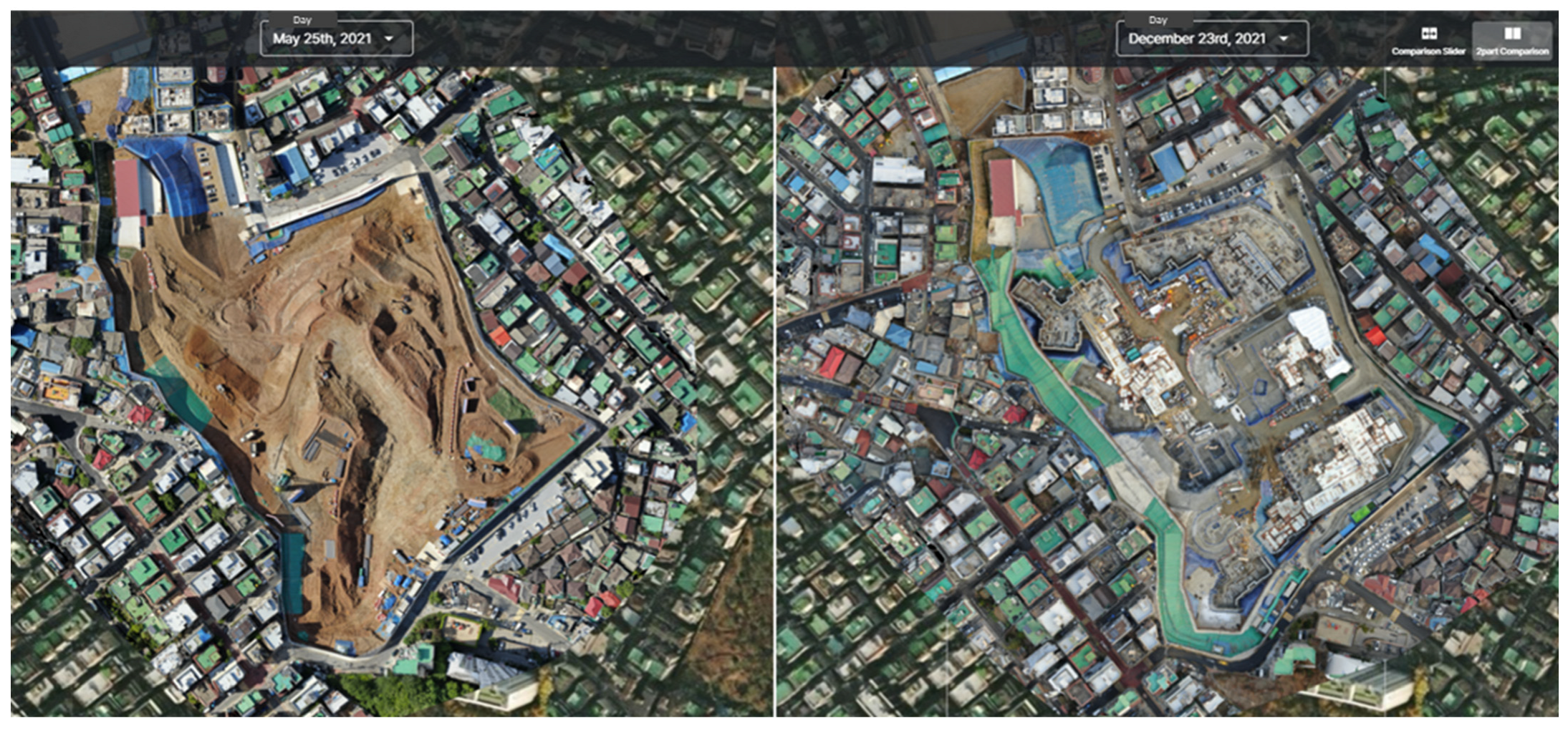
4.4. Site Monitoring
4.5. Documentation
5. Conclusions
Author Contributions
Funding
Institutional Review Board Statement
Informed Consent Statement
Data Availability Statement
Conflicts of Interest
Abbreviations
| BQ | Bill of quantities |
| DSM | Digital surface model |
| GCPs | Ground control points |
| GPS | Global positioning system |
| UAV | Unmanned aerial vehicle |
| TS | Total station |
References
- Kim, J.; Lee, D.; Seo, J. Task Planning strategy and path similarity analysis for an autonomous excavator. Autom. Constr. 2020, 112, 103108. [Google Scholar] [CrossRef]
- Cho, J.-W.; Lee, J.-K.; Park, J. Large-scale earthwork progress digitalization practices using series of 3D models generated from UAS images. Drones 2021, 5, 147. [Google Scholar] [CrossRef]
- El-Ashmawy, K.L.A. A Comparison between Analytical Aerial Photogrammetry, Laser Scanning, Total Station and Global Positioning System Surveys for Generation of Digital Terrain Model. Geocarto Int. 2014, 30, 1–9. [Google Scholar] [CrossRef]
- Beretta, F.; Shibata, H.; Cordova, R.; de Lemos Peroni, R.; Azambuja, J.; Costa, J.F.C.L. Topographic modelling using UAVs compared with traditional survey methods in mining. REM Int. Eng. J. 2018, 71, 463–470. [Google Scholar] [CrossRef]
- Akgul, M.; Yurtseven, H.; Gulci, S.; Akay, A.E. Evaluation of UAV- and GNSS-Based DEMs for earthwork volume. Arab. J. Sci. Eng. 2018, 43, 1893–1909. [Google Scholar] [CrossRef]
- Draeyer, B.; Strecha, C. White Paper: How Accurate Are UAV Surveying Methods? Pix4D White Paper 2016. Available online: https://pix4d.com/wp-content/uploads/2016/11/Pix4D-White-paper_How-accurate-are-UAV-surveying-methods.pdf (accessed on 20 June 2022).
- National Geographical Information Institute: Guidelines for Public Surveys Using UAVs. NGII Notice No. 2018-1075. 2018. Available online: https://www.ngii.go.kr/kor/board/view.do?sq=54859&board (accessed on 20 March 2022).
- Lee, S.B.; Song, M.; Kim, S.; Won, J.-H. Change monitoring at expressway infrastructure construction sites using drone. Sens. Mater. 2020, 32, 3923. [Google Scholar] [CrossRef]
- Tamin, M.A.; Darwin, N.; Majid, Z.; Mohd Ariff, M.F.; Idris, K.M.; Manan Samad, A. Volume estimation of stockpile using unmanned aerial vehicle. In Proceedings of the 2019 9th IEEE International Conference on Control System, Computing and Engineering (ICCSCE), Penang, Malaysia, 1 November 2019; pp. 49–54. [Google Scholar]
- Raeva, P.L.; Filipova, S.L.; Filipov, D.G. Volume computation of a stockpile—A study case of comparing GPS and UAV measurement in an open pit quarry. Int. Arch. Photogramm. Remote Sens. Spat. Inf. Sci. 2016, XLI-B1, 999–1004. [Google Scholar] [CrossRef]
- Jiang, Y.; Liang, W.; Geng, P. Application research on slope deformation monitoring and earthwork calculation of foundation pits based on UAV oblique photography. IOP Conf. Ser. Earth Environ. Sci. 2020, 580, 012053. [Google Scholar] [CrossRef]
- Al-Tahir, R.; Barran, T. Earthwork volumetrics with unmanned aerial vehicles: A comparative study. In Proceedings of the International Conference on Emerging Trends in Engineering & Technology (IConETech-2020), St. Augustine, FL, USA, 26–27 February 2020; pp. 687–697. [Google Scholar]
- Daukšys, M.; Daukšys, M.; Mockienė, J. Research on installation technologies of retaining walls with ground anchors. Sace 2020, 26, 53–64. [Google Scholar] [CrossRef]
- Kim, J.; Lee, S.; Seo, J.; Lee, D.-E.; Choi, H.S. The integration of earthwork design review and planning using UAV-based point cloud and BIM. Appl. Sci. 2021, 11, 3435. [Google Scholar] [CrossRef]
- Arango, C.; Morales, C.A. Comparison between multicopter uav and total station for estimating stockpile volumes. Int. Arch. Photogramm. Remote Sens. Spat. Inf. Sci. 2015, XL-1/W4, 131–135. [Google Scholar] [CrossRef]
- Kwon, S.; Park, J.-W.; Moon, D.; Jung, S.; Park, H. Smart merging method for hybrid point cloud data using UAV and LIDAR in earthwork construction. Procedia Eng. 2017, 196, 21–28. [Google Scholar] [CrossRef]
- Jiang, W.; Zhou, Y.; Ding, L.; Zhou, C.; Ning, X. UAV-Based 3D Reconstruction for hoist site mapping and layout planning in petrochemical construction. Autom. Constr. 2020, 113, 103137. [Google Scholar] [CrossRef]
- Bognot, J.R.; Candido, C.G.; Blanco, A.C.; Montelibano, J.R.Y. Building construction progress monitoring using unmanned aerial system (UAS), low-cost photogrammetry, and geographic information system (GIS). ISPRS Ann. Photogramm. Remote Sens. Spat. Inf. Sci. 2018, IV-2, 41–47. [Google Scholar] [CrossRef]
- Gheisari, M.; Rashidi, A.; Esmaeili, B. Using unmanned aerial systems for automated fall hazard monitoring. In Proceedings of the Construction Research Congress 2018, New Orleans, LA, USA, 29 March 2018; pp. 62–72. [Google Scholar]
- Harwin, S.; Lucieer, A. Assessing the accuracy of georeferenced point clouds produced via multi-view stereopsis from unmanned aerial vehicle (UAV) imagery. Remote Sens. 2012, 4, 1573–1599. [Google Scholar] [CrossRef]
- Hugenholtz, C.H.; Walker, J.; Brown, O.; Myshak, S. Earthwork volumetrics with an unmanned aerial vehicle and softcopy photogrammetry. J. Surv. Eng. 2015, 141, 06014003. [Google Scholar] [CrossRef]
- Álvares, J.S.; Costa, D.B. Construction Progress Monitoring Using Unmanned Aerial System and 4D BIM. In Proceedings of the 27th Annual Conference of the International Group for Lean Construction (IGLC), Dublin, Ireland, 3–5 July 2019; pp. 1445–1456. [Google Scholar]
- Xie, F.; Lin, Z.; Gui, D.; Lin, H. Study on Construction of 3D Building Based on Uav Images. ISPRS-Int. Arch. Photogramm. Remote Sens. Spat. Inf. Sci. 2012, XXXIX-B1, 469–473. [Google Scholar] [CrossRef]
- DelPico, W.J. Project Control: Integrating Cost and Schedule in Construction; John Wiley & Sons, Inc.: Hoboken, NJ, USA, 2013; ISBN 978-1-118-41913-7. [Google Scholar]
- Davis, P.; Baccarini, D. The Use of Bills of Quantities in Construction Projects—An Australian Survey. In Proceedings of the COBRA 2004 International Construction Research Conference of the Royal Institution of Chartered Surveyors, Leeds, UK, 7–8 September 2004. [Google Scholar]
- Razali, A.; Tajudin, A.; Fadzli, A.; Tajuddin, A. Importance and Functions of Bills of Quantities in the Construction Industry: A Content Analysis. Int. J. Eng. Sci. Invent. 2016, 5, 29–36. [Google Scholar]
- NGII Integrated Map. Available online: http://map.ngii.go.kr/ms/map/NlipMap.do (accessed on 26 July 2022).
- Abbasianjahromi, H.; Rajaie, H.; Shakeri, E. A Framework for Subcontractor Selection in the Construction Industry. J. Civ. Eng. Manag. 2013, 19, 158–168. [Google Scholar] [CrossRef]
- Wang, Y.; Huang, K.; Cao, Z. Probabilistic Identification of Underground Soil Stratification Using Cone Penetration Tests. Can. Geotech. J. 2013, 50, 766–776. [Google Scholar] [CrossRef]
- Motoyama, H.; Hori, M. Construction and Usefulness Verification of Modeling Method of Subsurface Soil Layers for Numerical Analysis of Urban Area Ground Motion. GeoHazards 2022, 3, 13. [Google Scholar] [CrossRef]
- Siebert, S.; Teizer, J. Mobile 3D Mapping for Surveying Earthwork Projects Using an Unmanned Aerial Vehicle (UAV) System. Autom. Constr. 2014, 41, 1–14. [Google Scholar] [CrossRef]
- DJI. DJI Phantom 4 Pro V2.0. Available online: https://www.dji.com/kr/phantom-4-pro-v2 (accessed on 26 July 2022).
- Korea Legislation Research Institute Act on Promotion of Utilization of Drones and Creation of Infrastructure Therefor. Available online: https://elaw.klri.re.kr/kor_service/lawView.do?hseq=53139&lang=ENG (accessed on 26 July 2022).
- Pix4D Ground Control Points: Why Are They Important? Available online: https://www.pix4d.com/blog/why-ground-control-points-important#:~:text=Pix4D%20makes%20it%20possible%20to,the%20term%20ground%20control%20points (accessed on 26 July 2022).
- Pix4D. Pix4Dmapper. Available online: https://www.pix4d.com/product/pix4dmapper-photogrammetry-software (accessed on 26 July 2022).
- Kielhauser, C.; Renteria Manzano, R.; Hoffman, J.J.; Adey, B.T. Automated Construction Progress and Quality Monitoring for Commercial Buildings with Unmanned Aerial Systems: An Application Study from Switzerland. Infrastructures 2020, 5, 98. [Google Scholar] [CrossRef]
- Meissa. Available online: https://www.meissa.ai/en/ (accessed on 26 July 2022).
- Mantey, S.; Aduah, M.S. Comparative Analysis of Stockpile Volume Estimation Using UAV and GPS Techniques. GM 2021, 21, 1–10. [Google Scholar] [CrossRef]


| GCP | x (m) | y (m) | z (m) |
|---|---|---|---|
| GCP1 | 194,565.142 | 544,356.834 | 41.643 |
| GCP2 | 194,657.481 | 544,362.629 | 38.151 |
| GCP3 | 194,667.442 | 544,348.826 | 38.775 |
| GCP4 | 194,734.263 | 544,194.89 | 54.503 |
| GCP5 | 194,693.649 | 544,142.25 | 59.505 |
| GCP6 | 194,677.789 | 544,140.788 | 60.644 |
| GCP7 | 194,582.005 | 544,092.945 | 75.396 |
| GCP8 | 194,524.529 | 544,207.286 | 73.361 |
| GCP9 | 194,451.559 | 544,296.509 | 64.822 |
| GCP10 | 194,461.096 | 544,440.59 | 60.216 |
| Soil Layer | Quantity (m3) | Quantity Difference (m3) | |
|---|---|---|---|
| GPS | UAV | ||
| Soil and weathered soil | 222,541 | 235,103 | −12,562 |
| Weathered rock | 52,212 | 55,226 | −3014 |
| Soft and hard rock | 79,646 | 61,554 | 18,092 |
| Total | 354,399 | 351,883 | 2516 |
| Soil Layer | Unit Price (USD/m3) | Quantity (m3) | Cost (USD) | Cost Difference (USD) | Remarks | ||
|---|---|---|---|---|---|---|---|
| GPS | UAV | GPS | UAV | ||||
| Soil and weathered soil | 1.067 | 222,541 | 235,103 | 237,451 | 250,855 | −13,404 | |
| Weathered rock | 2.311 | 52,212 | 55,226 | 120,662 | 127,627 | −6965 | |
| Soft and hard rock | 11.244 | 79,646 | 61,554 | 895,540 | 692,113 | 203,426 | Vibration control blasting |
| Total | 354,399 | 351,883 | 1,253,653 | 1,070,595 | 183,057 | ||
Publisher’s Note: MDPI stays neutral with regard to jurisdictional claims in published maps and institutional affiliations. |
© 2022 by the authors. Licensee MDPI, Basel, Switzerland. This article is an open access article distributed under the terms and conditions of the Creative Commons Attribution (CC BY) license (https://creativecommons.org/licenses/by/4.0/).
Share and Cite
Park, H.C.; Rachmawati, T.S.N.; Kim, S. UAV-Based High-Rise Buildings Earthwork Monitoring—A Case Study. Sustainability 2022, 14, 10179. https://doi.org/10.3390/su141610179
Park HC, Rachmawati TSN, Kim S. UAV-Based High-Rise Buildings Earthwork Monitoring—A Case Study. Sustainability. 2022; 14(16):10179. https://doi.org/10.3390/su141610179
Chicago/Turabian StylePark, Hyung Cheol, Titi Sari Nurul Rachmawati, and Sunkuk Kim. 2022. "UAV-Based High-Rise Buildings Earthwork Monitoring—A Case Study" Sustainability 14, no. 16: 10179. https://doi.org/10.3390/su141610179