1. Introduction
The coal seams in the northwestern region of China are generally shallow buried and superior deposits. A large number of modern mines have been built with high-intensity mining as the obvious indigenous characteristic [
1]. In recent years, with the development of large mining heights and the technology and equipment of LTC, longwall top-coal caving with large mining heights (LTCLMH) has been widely used in extra-thick coal seams [
2]. The stope space formed by LTC is large and as the disturbance distance overlay multiplies, dynamic disasters occur frequently. Among them, the strong strata behaviors of the roof in the initial mining and caving stages often cause supports to shrink sharply, with the rib spalling of the coal wall and the roof falling before the canopy, and even leads to support crushing accident, which threaten the safety of personnel and equipment in the working face and seriously affect production efficiency [
3,
4,
5,
6].
The LTC working face is generally characterized by intense mining pressure, large dynamic load coefficients, frequent opening of safety valves and severe mine pressure in the middle of the working face. To reveal the theoretical rock structure characteristics and the formation mechanism of severe rock pressure in LTCLMH, a series of mining-induced overlay strata structure models were proposed, such as ‘the up the masonry beam and down the inverted step combination type of cantilever beam’ [
7], ‘the combined short cantilever beam/articulated rock beam’ [
8] and ‘the horizontal O–X breakage of far-field key strata’ [
9]. Because of the severe strata behavior conditions of fully mechanized cave mining under multi-gob and MKS, the reasonable selection of support and the efficient application of roof crack prevention and control measures are necessary to ensure safe mining [
10,
11]. In addition, the study of mine pressure under the conditions of single-key strata and MKS in the western mining area shows that the migration and breaking of the key strata determine the mine pressure behavior of the working face [
12]. However, there are few studies on the prevention and control of strong mine pressure in the early stages of LTC under MKS.
In this paper, based on a case study in a Chinese coal mine, we studied the principle of strong mine pressure control in the initial mining and caving stages under MKS. To avoid the interaction among broken MKS in the initial mining stage, key strata were evaluated and the roof breaking step was analyzed, and the rock structure model of coal caving after the initial weighting under MKS was established. The simulation analysis and practice verified the prevention and control effects of coal caving on initial mining dynamic pressure accidents after the initial weighting under MKS, and the special mine pressure law in initial mining and initial caving under MKS is summarized.
2. Background
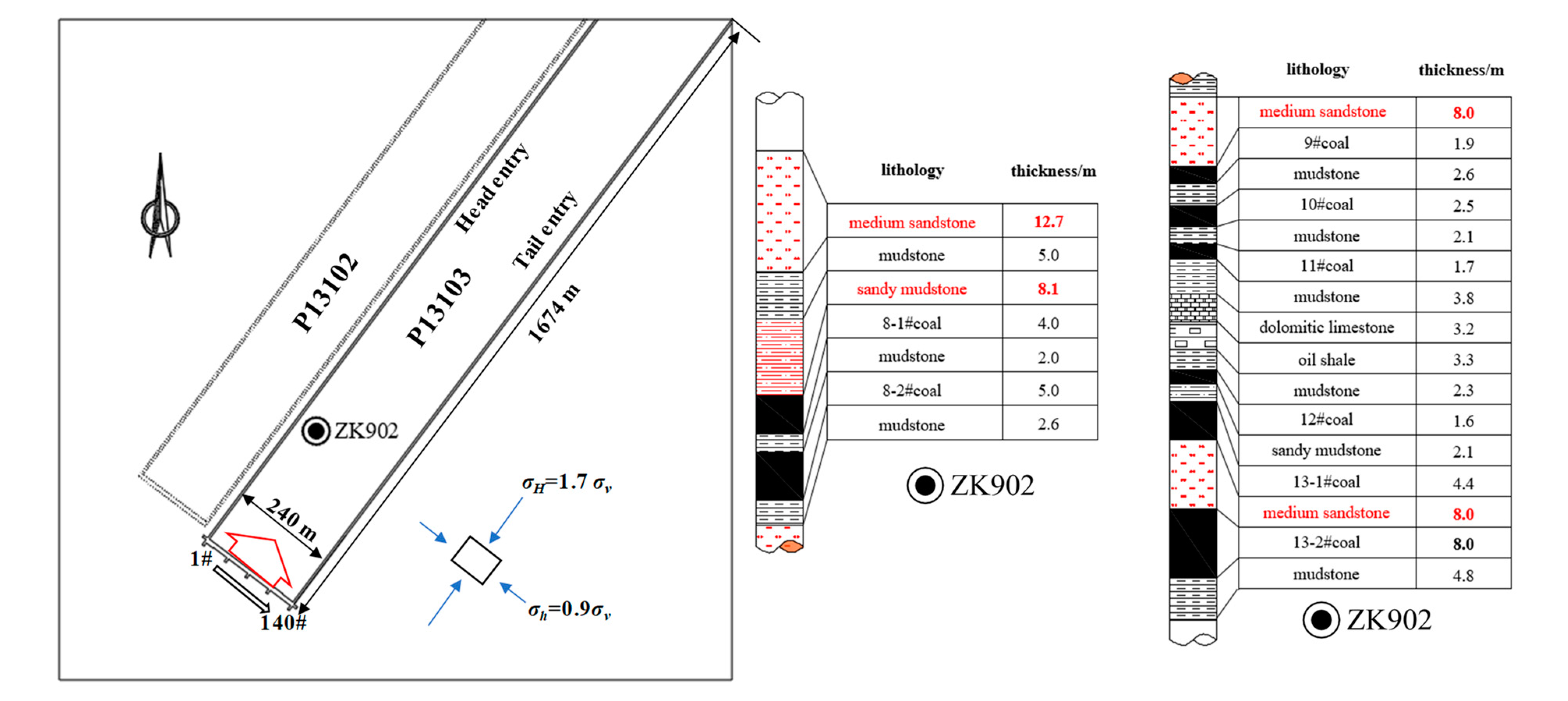
Shaping Coal Mine is located in the southeast of Hequ County and is located in the Hebaopian Mining Area of the Hedong Coalfield. The average coal thickness of the number 13 coal seam in the first panel is 13 m, and it is part of an extra-thick coal seam. The detection of coal thickness from the two entries shows that most of the areas of the first panel of 13103 branch into seam numbers 13-1 and 13-2. Due to the large change in the thickness of the number 13-1 coal seam, the middle sandwich is medium sandstone with an average thickness of 8 m, and only coal seam 13-2 is mined; the two entries into the area are arranged along the floor of the number 13-2 coal seam. P13103 is 1674 m long and 240 m wide, with a total of 140 hydraulic supports, an average inclination angle of 3° and a burial depth of 200 m. The equipment used in LTCLMH adopts ZFY13600/27/45D-type hydraulic supports and MG650/1620-WD-type shearers from Beijing Coal Machinery Factory, with a machine mining height range of 2.7–4.5 m. In situ stress measurements by the downhole multi-point method at the site showed that the initial stress direction is consistent and belongs to the slip type [
13]. The vertical stress (σ
v) is formed by the self-weight of the overlying strata. The maximum horizontal principal stress (σ
H) is 1.7 times the vertical stress, the direction is NW43.8°, which is approximately parallel to the working face’s advance direction and the minimum horizontal principal stress (σ
h) is 0.9 times the vertical stress. The overlying structure according to drill hole ZK902 inside P13103 is shown in
Figure 1. The basic roof of P13103 is 8.0-meter thick medium sandstone, and there are multiple thick and hard layers above it; see the red rock layer in the columnar in
Figure 1. Since the mine pressure in the initial mining stage of the adjacent mine under similar geological engineering conditions is intense, and prop crushes by dynamic pressure and roof collapse accidents have occurred, it is necessary to study the roof structure and mine pressure characteristics under similar conditions [
14,
15].
3. Roof Structure and Breaking Characteristics
The pressure behavior of the stope is dominated by the breaking structure of the upper strata. The previous mining pressure theory for stope mainly studied the influence of the direct roof and the basic roof near the stope [
16,
17]. However, the practice of large mining–height mining and top-coal caving cases show that, with the increase of the total mining height, the development heights of the caving zone and fracture zone increase in an exponential manner, and the high-level key strata (HKS) also affect the mine pressure of the working face [
11]. The physical and mechanical parameters of coal and rock according to the ZK902 borehole in P13103 are shown in
Table 1.
3.1. Overburden Key Strata Evaluation
For each rock layer of a different thickness and strength in the overburden rock, the basic roof load is calculated according to combination beam theory [
18,
19]:
where (
qn)
1 is the load accumulated on the basic roof imposed by the n-layer overburden, MPa; and
γn,
hn,
En is the volume weight (MN/m
3), thickness (m) and elastic modulus (MPa) of the
nth-layer overburden, respectively.
If the conditions
(qn+1)1 <
(qn)1 are met, the
n + 1 strata is the key strata of the overlay. According to the parameters in
Table 1, the parameters of middle sandstone B, sandy mudstone C, and medium sandstone D in the overlay above the number 13 coal seam do not contribute to the load of the basic roof, middle sandstone A. The calculation results are shown in
Table 2, and the four key strata are labeled as K1 to K4 for the convenience of the following description.
3.2. The Breaking Step of the Key Strata
Practice shows that the height of the caving zone in fully mechanized cave mining ranges from 4 to 6 times the mining height. Therefore, the key strata K1 and K2 are mainly considered when analyzing the collapse of the roof. The first panel is abstracted as the condition of a four-sided fixed support, and the pressure step of the first mine is calculated according to [
20]:
where
b is the width of the panel, m and
lm is the pressure step coefficient of the roof.
The key strata K1 and K2 are used as the basic roof, and the pressure steps where the first break occurs are 34.6 m and 41.2 m, respectively. After the initial break, the corresponding roof is calculated as a cantilever beam, and the periodic pressure step distances are 14.2 m and 16.8 m, respectively.
According to the theoretical calculation results above, the breaking steps of K1 and K2 above P13103 are similar when the initial weighting is applied. Compared with production experience under similar conditions, the LTC working face has a longer weighting time, which can last for 1–2 days. The mine pressure appears to be severe, with the dynamic load factor reaching 1.8 [
7]. The average daily advance distance of P13103 was designed to be 4 m. Considering the hysteresis of roof collapse, the two key strata will break and interact, resulting in the superposition of mine pressure, which in turn leads to dynamic crush accidents [
21].
4. Key Strata Structure Control
When pressure is applied for the first time, the span of the basic roof is generally relatively large and the scope of influence is far, which is the key stage in preventing roof collapse accidents. Especially with the combination of LTCLMH and MKS conditions, where the superimposed near-field MKS breaking-step distance is similar, it is necessary to control the overlying rock structure from the initial mining in order to avoid the direct impact on the working face caused by the breaking of the basic roof block after coal seam mining, which acts by pushing down on the stope space and causes crush accidents. Although many mines have achieved good results by using deep-hole blasting and hydraulic fracturing for the initial roof caving, the efficiency of roof caving under the conditions of MKS is low and the effect is difficult to guarantee [
22]. In addition, Shaping Coal Mine is a resource-integrated mine. There is an old mine fire area within 300 m of the open cut in front of the first mining working face, and the safeguarding measures of ground nitrogen injection and underground ventilation regulation were adopted. Avoiding the sudden increase in the height of the cave zone during the initial caving results in a connection between the working face and the fire area. From the aspect of the mining process parameters, the main consideration is to realize the control of the strata overlying the stope [
23].
4.1. Low-Level Double Key-Strata Structure Control
The practice of backfill mining and slice mining shows that mining thickness is one of the most important factors affecting the migration of overlying rock [
24]. Due to the caving and dilatation characteristics of the overlying rock above the gob [
25,
26], the thickness of the direct roof required to fill the gob is Σ
h.
According to the mining conditions at P13103, when the mining thickness
m is 8.0 m, the recovery rate
φ of the fully mechanized caving face is taken as 80%, the roof is medium hard, the bulking coefficient
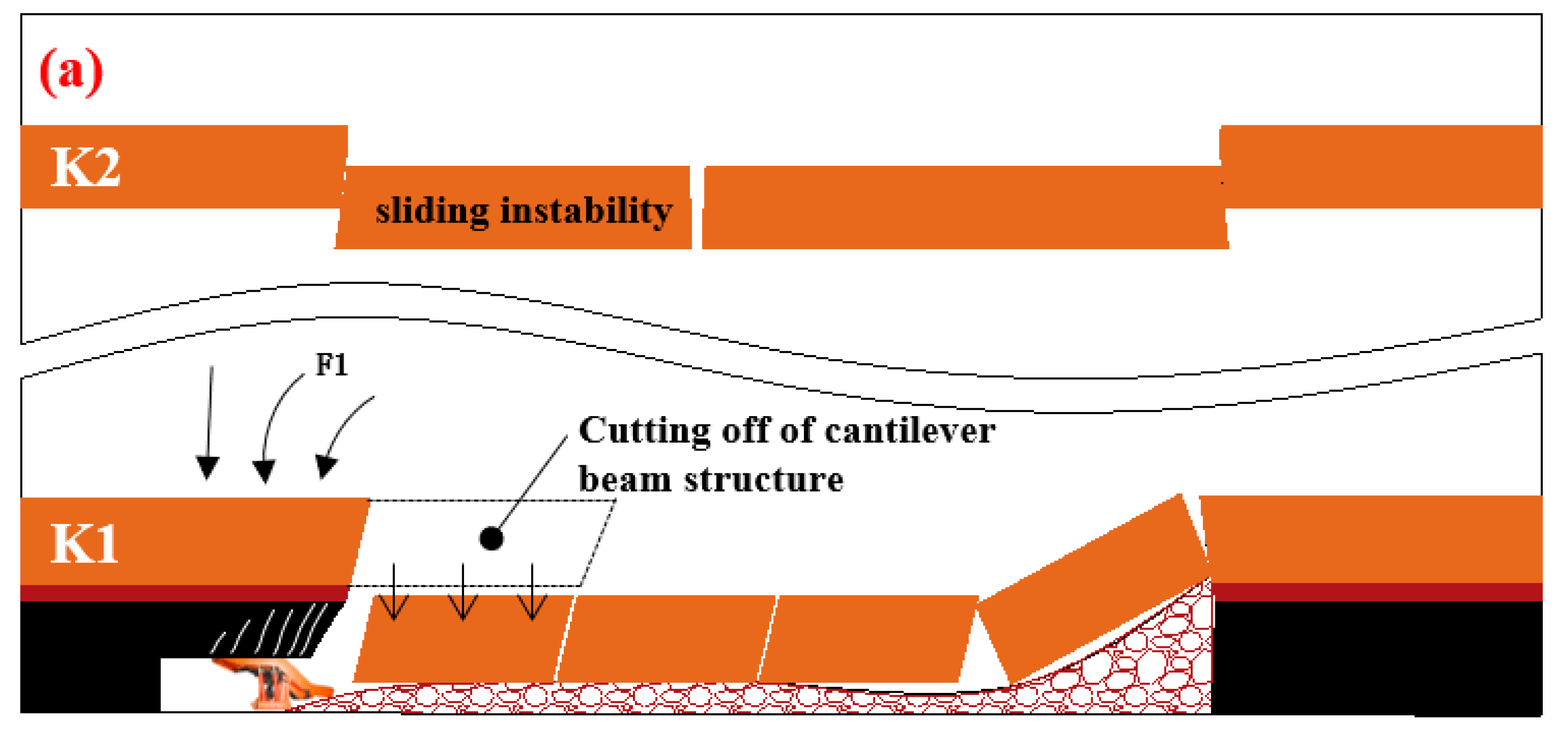
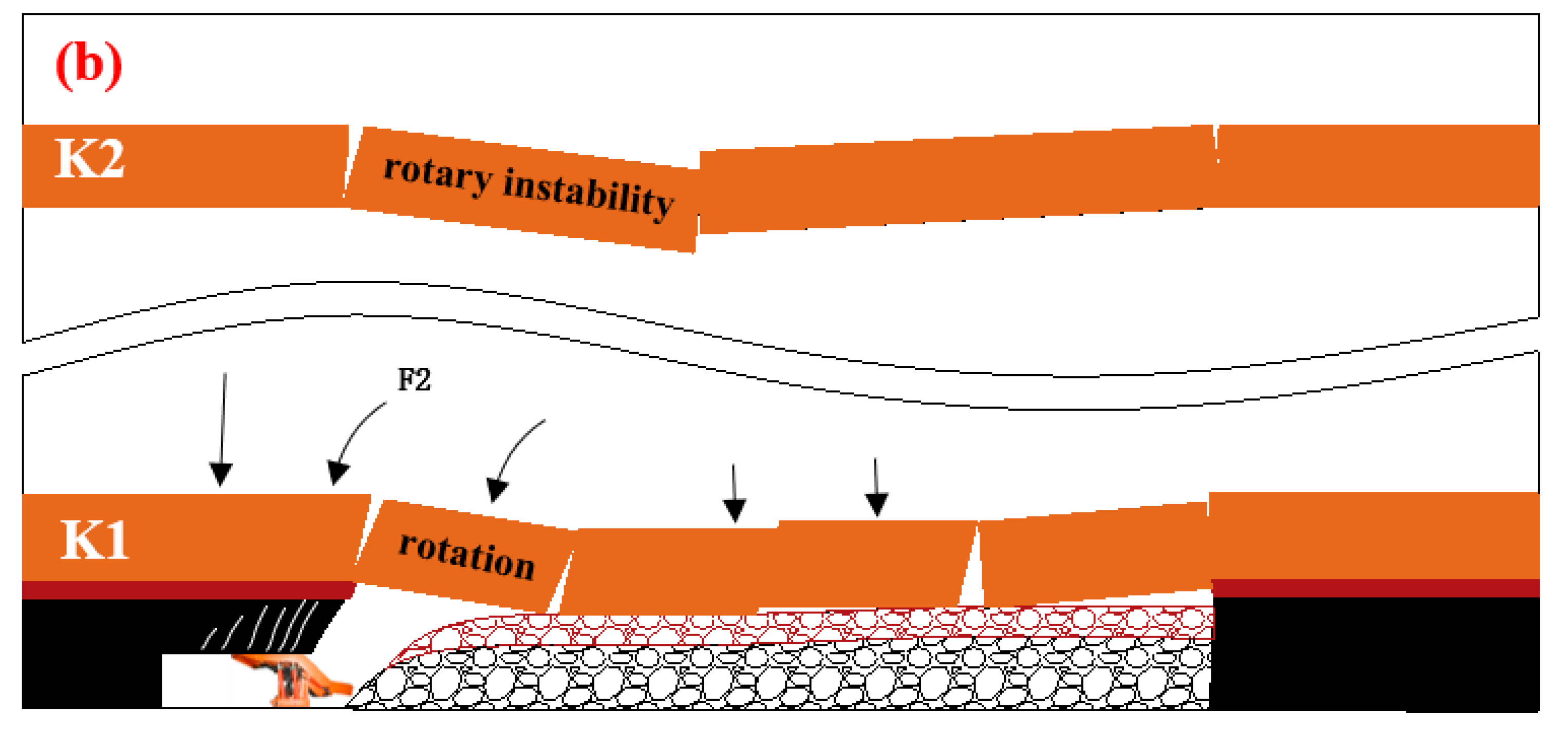
kp is taken as 1.25, and the caving roof height is 25.6 m. The low-level K1 is not able to form a masonry beam structure and then transform into a direct roof, forming a cantilever beam structure near the stope. When K2 breaks, it is difficult for the K1 layer to form a stable structure to protect the stope space. According to this, it is necessary to reduce the mining height in the initial mining stage, use top-coal fragmentation filling to reduce the roof collapse angle of the goaf and promote the formation of a masonry beam structure in the low-level key strata (LKS) so the broken rock blocks are hinged to form an arch towards the front of the coal wall and mining face. The gravel in the open area transmits the load. When the HKS breaks for the first time, the low-level masonry beam structure is used to shield the stope space.
Figure 2 shows the overburden structure models of the different initial mining schemes of LTCLMH.
4.2. The Initial Mining Height Determined
According to the caving and dilation characteristics of the near-stope key strata [
27,
28,
29], to promote the formation of a masonry beam structure in the LKS, it is necessary to satisfy the requirement that the thickness of the caving roof is less than the sum of the thickness of the LKS and the mining layer, as shown in Equation (4).
where
M is the thickness of the coal seam, m;
m is the actual mining thickness, m;
φ is the recovery rate of the working face,
kp is the bulking coefficient of the rock, 1.15–1.30; and
hi is the thickness of each rock strata above the recovery seam, m.
According to the actual conditions of Shaping Coal Mine, the average thickness of seam number 13 in the initial mining area of 90 m is 8.0 m, and the average thickness of K1 is 8.7 m. The working face recovery rate φ is 93% for fully mechanized caving and 80% for LTC; for the existence of top coal, the bulking coefficient kp is taken as 1.30, i.e., the mining thickness needs to be less than 4.1 m. Combined with the equipment conditions of P13103, it is finally determined that the mining height is designed to be 4.0 m without the top-coal caving process in the initial mining stage.
5. Numerical Simulation
Coal caving generally starts at about 20 m in the initial mining stage. According to
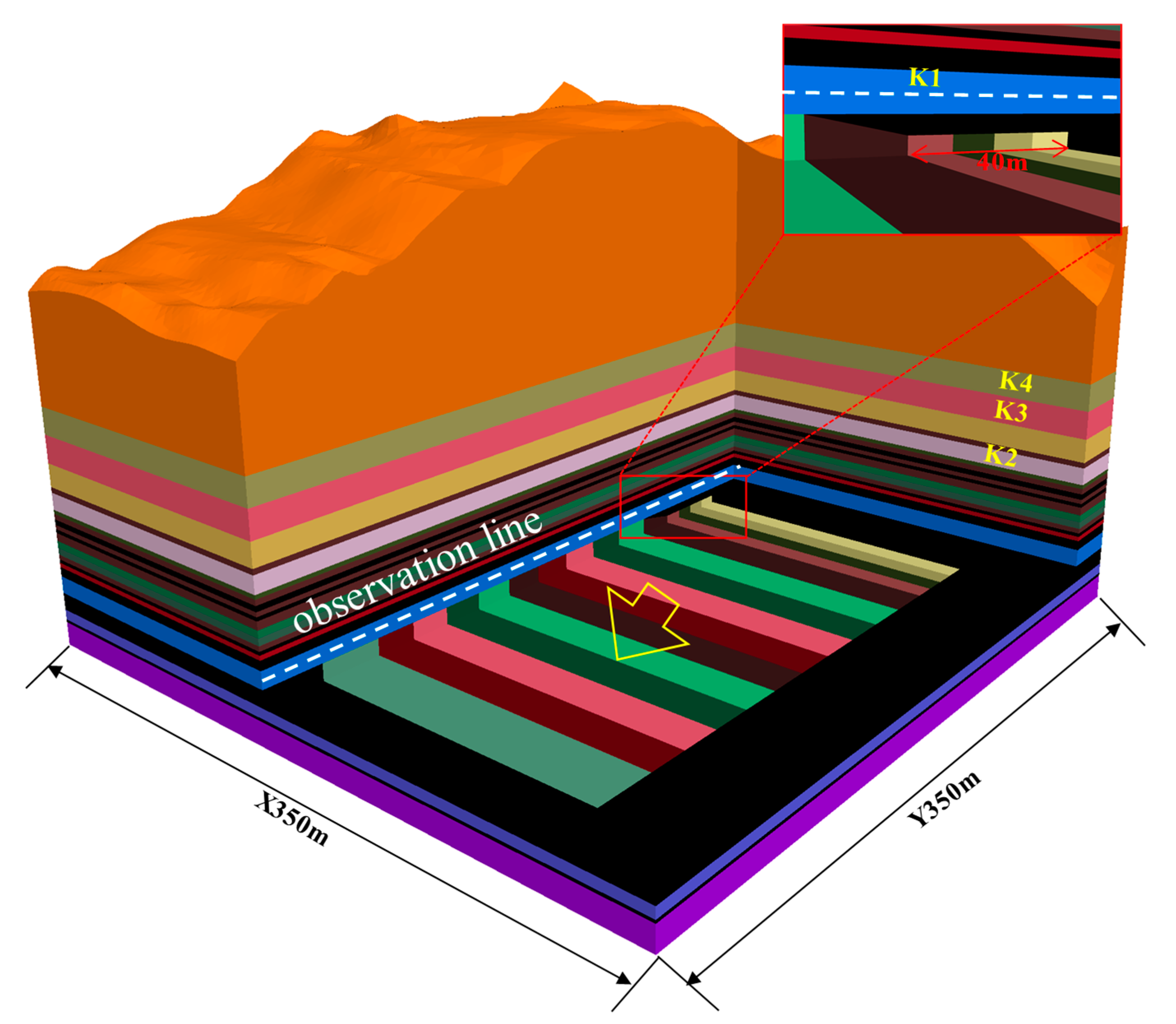
Section 3.2 and 4.2, the initial mining plan for the prevention and control of severe weighting under MKS in P13103 of Shaping Coal Mine is as follows: the initial mining range is about 40 m and the height is 4 m without top-coal caving. After first weighting, the top-coal caving was gradually started, fully caving at 60 m with the mining–caving ratio of 1:1. Based on this, numerical simulations were used to analyze the strata movement characteristics.
In order to reflect the characteristics of the undulating surface and the mining height transition of the working face in detail, the FLAC3D numerical model was established based on the strata histogram of P13103 and the surface topography. The model was 350 m in the X direction and 350 m in the Y direction, the Z direction was modeled on the surface, the displacement was limited around the area and at the bottom, and a 50 m boundary coal pillar was left. Stress boundary conditions were set according to the in situ stress test results. The model is shown in
Figure 3. In Scheme A, with the initial advance distance of 20 m, the top coal was mined for 4 m without caving, after which the coal caving height gradually increased, with full caving beginning as the advance distance reached 40 m with a mining–caving ratio of 1:1. In Scheme B, with the initial advance distance of 40 m, the top coal was mined for 4 m without caving, after which the coal caving height gradually increased, with full caving beginning as the advance distance reached 60 m with a mining–caving ratio of 1:1.
The Mohr–Coulomb model was used for the coal strata. Combined with
Table 1, the parameters of the complete rock sample were converted into rock mass parameters by RQD to characterize the mechanical response of the original rock [
4,
30]. The Null model was used for step-by-step excavation, the large strain calculation mode was turned on, all calculations were carried out to equilibrium and the displacement and stress were transferred between layers through the ‘interface’ [
31].
5.1. Initial Mining Pressure Characteristics
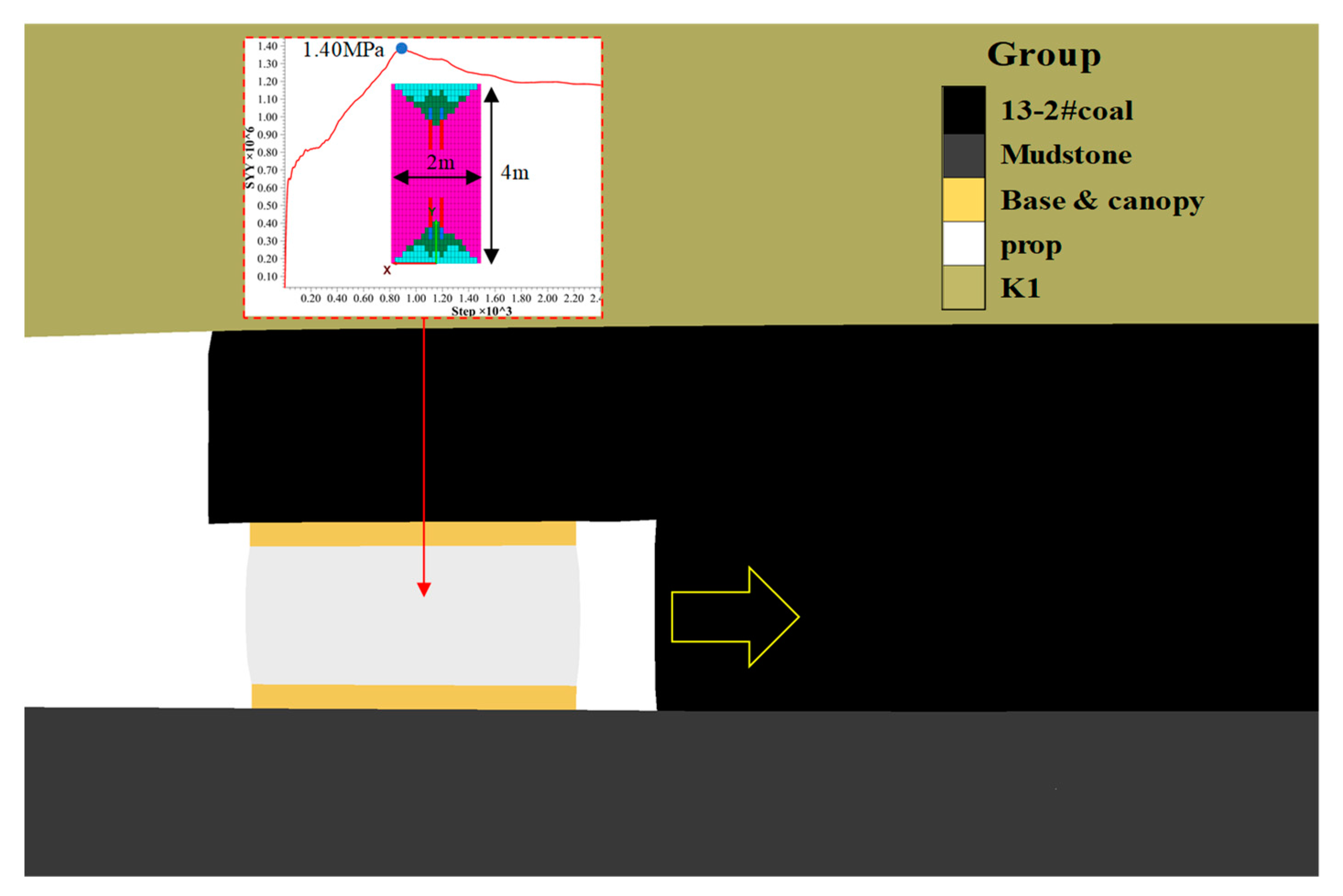
In the step-by-step excavation process, hydraulic supports are grouped in the range of 2–8 m behind the coal wall by FLAC3D. The top and bottom beams are elastic models [
32]. The Mohr–Coulomb constitutive model for characterizing the support performance of hydraulic supports was used [
33]. The support strength was calibrated to 1.4 MPa, according to the support parameters, as shown in
Figure 4.
The middle part of the working face with the most severe mining pressure was selected for monitoring. The results of the mining pressure characteristics of the stope corresponding to Scheme A and Scheme B are shown in
Table 3. Comparing the two schemes at the same advance distance, it can be seen that the advance abutment pressure and the damage ratio [
34,
35,
36] of the support in Scheme A are significantly greater than those in Scheme B. In Scheme A, the damage ratio of support is as high as 74% when recovery is 60 m, which is prone to inducing support crushing accidents. However, the damage ratio of support does not exceed 50% in Scheme B, and the vertical stress of the coal wall in the advance position does not increase significantly.
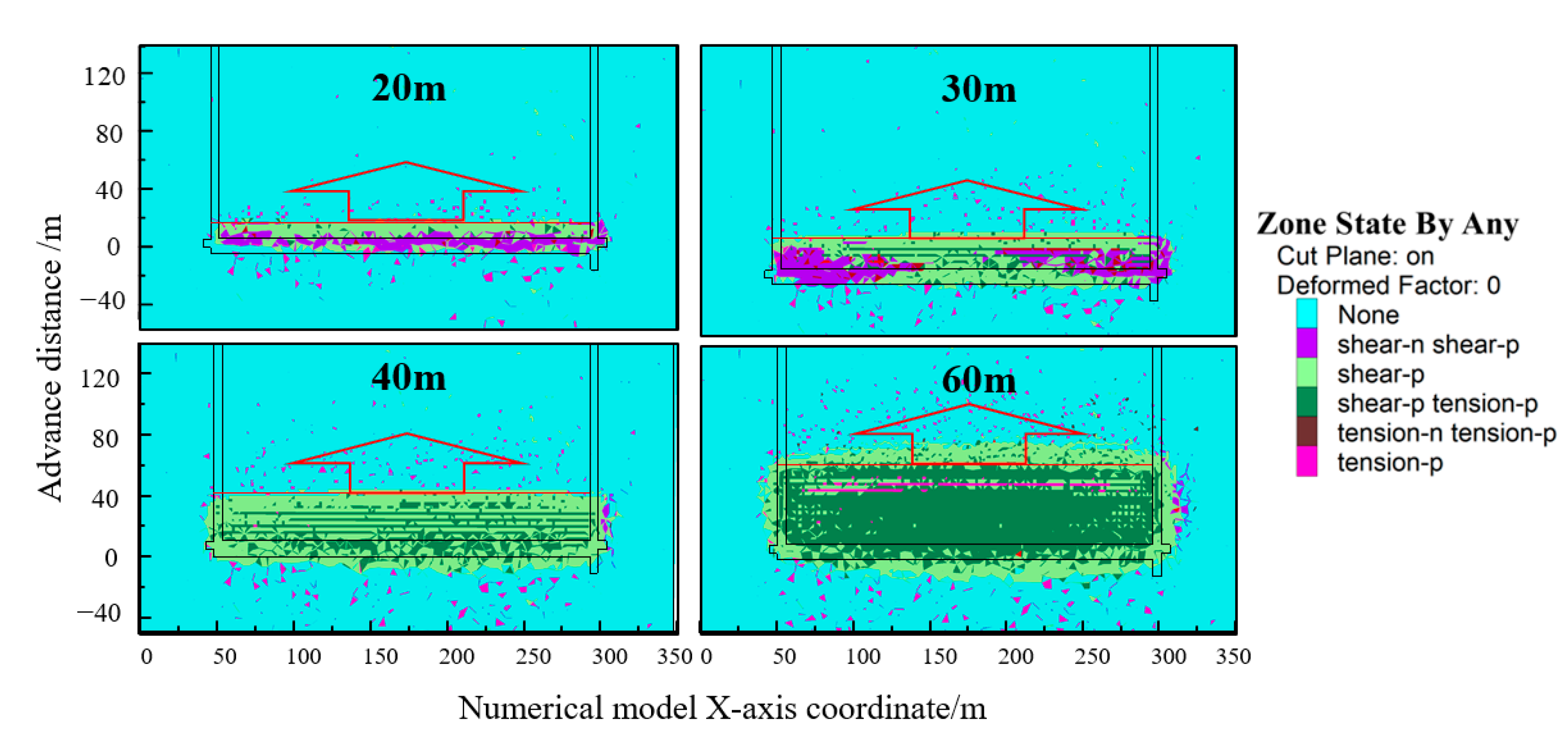
5.2. Mining Response Characteristics of the Key Strata of Scheme B
Since Scheme B had a better effect on the prevention and control of severe mining-induced pressure, the mining response of the key strata in the initial mining stage was analyzed. During the initial mining process of 60 m, the K1 had a plastic zone from the open cut. When the mining distances were 20 m and 30 m, shear failure continued to occur behind the working face. After 40 m of mining, the central part of the gob experienced a tensile-shear failure, the boundary of the gob mainly shear failure, and the roof collapsed, corresponding to the first weighting when the mining height was 4 m. After the working face was mined for 60 m, the roof plastic zone developed ahead of the working face, which is generally considered to be caused by the cantilever beam structure, as shown in
Figure 5.
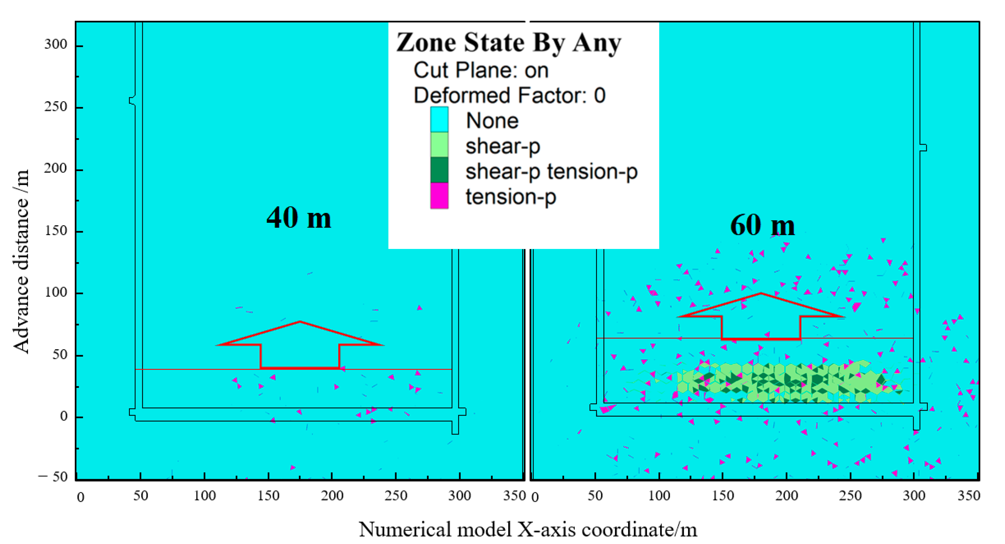
For the K2 strata, when the advance distance was 40 m, the plastic zone developed sporadically, resulting in damage. When the advance distance was 60 m, the roof suffered plastic failure. The lag of the working face was about 15 m, and the damage occurred in the middle of the goaf, which proved that the K2 did not suffer from shear-off failure, as shown in
Figure 6.
The observation line was arranged in K1 by Tecplot to monitor the vertical stress and displacement of the mining state with the typical plastic failure of the key strata in the initial mining process of P13103 (
Figure 3). The results are shown in
Figure 7.
From
Figure 7a, it can be seen that with the working face advancing, in the process recovery distance of 30–60 m, the peak value of the advanced abutment pressure increases, and the influence range of abutment pressure expands gradually. The peak value of stress in the advance position changed little after the recovery distance to 60 m and stabilized. When the recovery distance reached 100 m, the gob compaction stress at the open cut side gradually recovered. When recovery distance reaches 240 m, the gob presented a square shape and the ground pressure appeared violently. The gob compaction stress at the open cut side basically recovered to the original rock stress, and the stress concentration coefficient at the advanced position was greater than 2. In
Figure 7b, in the process of the recovery distance of 30–60 m, the vertical displacement increased rapidly, the displacement of recovery distance to 30–40 m increased to twice the value, the maximum subsidence reached 1 m, and K1 first collapsed. When the displacement of 40–60 m was doubled, the maximum subsidence was 3 m. Compared with the development characteristics of the plastic zone, when K2 was first broken, the caving zone increased rapidly, and the mine pressure behavior was more intense than the initial weighting. When mining to 100 m, the maximum roof subsidence was close to the initial mining height, with the roof caving fully. The gob behind the working face was gradually compacted when mining to 240 m, and the maximum displacement in the middle of the gob was greater than 7 m.
The analysis shows that under the current equipment conditions, Scheme A is not conducive to the stability of the roof structure of the LKS, as it is easy to induce dynamic load accidents such as support crush accidents. It is an effective means for the prevention and control of strong mine pressure to select the top-coal caving after the initial weighting in the initial mining and caving stage of the extra-thick coal seam. The bedding rock was broken from the bottom to the top, and the MKS were broken layer by layer, resulting in successive weighting. The second weighting intensity was greater than the first weighting, and then the strata behavior of the working face tended to be stable.
6. Field Measurement of Mine Pressure
The initial mining was organized according to Scheme B, and the prop resistance of the hydraulic support in the working face was monitored. It was observed that the pressure changes near entries of the working face were not obvious, and the pressure in the range of 30–110 # support in the middle was obvious. The mine pressure was monitored every 10 supports. P13103 stops from the open cut; the first four weightings are shown in
Table 4.
According to the statistical data, the initial breaking step of K1 is 41 m, which is consistent with the theoretical analysis result. Affected by the coal seam dip angle, the maximum dynamic load coefficient along the working face direction is distributed in supports 40–70, which is located in the middle and lower parts of the working face. In the process of mining 90 m forward from open cut, the statistical average dynamic load coefficient first increases and then decreases, and the average dynamic load coefficient of the second weighting is the largest. After the first pressure, the pressure duration increased. The rock pressure characteristics show that the height of the caving zone increases significantly and tends to be stable after the first weighting. The dynamic load formed by the first breaking of K2 is greater than K1. The rock pressure of the second weighting stope is the most intense. The safety valve of the support in the middle of the working face is partially opened, and the maximum depth of the rib spalling of the coal wall is 0.6 m. There is no roof falling in front of the support and shrinkage of props. It effectively avoids the dynamic pressure disaster when the first roof caves, and realizes the safe mining of the working face.
7. Discussion
The findings of this paper clearly show the formation principle, prevention and control practice of strong mine pressure in the initial mining and caving stage with MKS in a shallow, extra-thick coal seam. The analysis results show that the breaking distance of low double key strata is similar. Because of the strong mine pressure that occurred in adjacent mines with similar geology and equipment conditions, a targeted mining scheme is proposed.
Generally, the basic roof presplits before first weighting, which can effectively reduce the breaking step of the roof and realize the prevention and control of severe mine pressure. Under complex conditions, such as MKS and mining under fire area, top-coal caving after the initial weighting should be adopted, and the initial mining height should be determined according to the overlying structure, breaking roof structure and bulking characteristics so as to promote the transformation of the broken basic roof from cantilever beam to masonry beam structure that forms a shield and avoids the strong mine pressure impact stope formed by the MKS breaking interaction.
The interaction of low-level double key strata is closely related to factors such as mining thickness, interlayer height and strata structure. In the case of small mining thickness and large interlayer height, the traditional near-field key-strata-breaking dominant mine pressure is still applicable. The study of the MKS interaction criteria is a topic worthy of exploration in LTCLMH.
In the process of the numerical simulation analysis, the subsidence value of the basic roof is almost equal to the mining height, which indicates that the finite element simulation method is insufficient to characterize the bulking characteristics of the gob and the caving zone. The strata in the caving zone that adopt the double-yield constitutive model can better reflect the surface subsidence and the front abutment pressure distribution characteristics, while the mining response of the basic roof inside the caving zone is ignored. Therefore, the mining response in the caving zone is worth exploring in the future.
The research results are limited by the finite element numerical simulation method. Although the large strain and the contact problem between the layers are fully considered in the calculation, there are deficiencies in the analysis of the dilatancy in the caving zone and the breaking roof structure. The promotion of the new finite discrete element calculation method is expected to improve the accuracy of the analysis of such problems.
8. Conclusions
In this paper, the prevention and control principle of strong mine pressure in the initial mining and caving stage under the condition of MKS was analyzed. The engineering application under the geological conditions of MKS and the overlying fire zone shows that the strata behavior of the mining scheme is relaxed. The main conclusions are as follows:
- (1)
The basic roof structure is the key to the control of strong mine pressure in the initial mining and caving stage;
- (2)
The calculation formula of the initial mining height to form the masonry beam structure after the initial breaking of the basic roof is proposed and the breaking roof structure model under two mining schemes was established;
- (3)
The duration of mine pressure tends to be stable with the height of the caving zone fully developed;
- (4)
The mining scheme of gradual coal caving after the first weighting of P13103 realizes safe mining in the initial mining and caving stage with MKS.
Author Contributions
Conceptualization, K.M. and S.T.; methodology, D.Z.; software, W.L. and L.T.; validation, D.W., X.L. and H.T.; formal analysis, K.M.; writing—original draft preparation, K.M.; writing—review and editing, S.T. and D.Z.; project administration, S.T. All authors have read and agreed to the published version of the manuscript.
Funding
This research was funded by the National Natural Science Foundation of China (Nos.51874281), the National Natural Science Foundation for Young Scientists of China (Nos.52004270) and the Postgraduate Research and Practice Innovation Program of Jiangsu Province (KYCX19_2174; KYCX21_2347).
Institutional Review Board Statement
Not applicable.
Informed Consent Statement
Not applicable.
Data Availability Statement
Data sharing not applicable.
Acknowledgments
The authors would like to thank the engineering technicians at the Shaping Coal Mine for their enthusiastic assistance and suggestions.
Conflicts of Interest
The authors declare no conflict of interest.
Glossary
| h | thickness, m |
| ρ | density, m |
| E | elastic modulus, GPa |
| μ | Poisson ratio, 1 |
| Tl | tensile strength, MPa |
| b | width of the panel, m |
| lm | the pressure step coefficient of the roof, 1 |
| φ | the recovery rate, % |
| kp | the bulking coefficient, 1 |
| m | the mining thickness, m |
| M | the thickness of the coal seam, m |
| hi | the thickness of each rock strata above the mining coal seam, m |
| MKS | multiple key strata |
| P13103 | the 13103 Panel |
| LTC | longwall top-coal caving |
| LTCLMH | longwall top-coal caving with large mining height |
| HKS | the high-level key strata |
| RQD | rock quality designation |
| LKS | the low-level key strata |
References
- Guo, W.B.; Zhao, G.B.; Lou, G.Z.; Wang, S.R. A New Method of Predicting the Height of the Fractured Water-Conducting Zone Due to High-Intensity Longwall Coal Mining in China. Rock Mech. Rock Eng. 2019, 52, 2789–2802. [Google Scholar] [CrossRef]
- Wang, J.; Yang, S.; Wei, W.; Zhang, J.; Song, Z. Drawing mechanisms for top coal in longwall top coal caving (LTCC): A review of two decades of literature. Int. J. Coal Sci. Technol. 2021, 8, 1171–1196. [Google Scholar] [CrossRef]
- Yu, B.; Zhu, W.; Li, Z.; Gao, R.; Liu, J. Mechanism of the instability of strata structure in far field for super-thick coal seam mining. J. China Coal Soc. 2018, 43, 2398–2407. [Google Scholar]
- Bai, Q.S.; Tu, S.H.; Chen, M.; Zhang, C. Numerical modeling of coal wall spall in a longwall face. Int. J. Rock Mech. Min. 2016, 88, 242–253. [Google Scholar] [CrossRef]
- Zhang, Q.L.; Yue, J.C.; Liu, C.; Feng, C.; Li, H.M. Study of automated top-coal caving in extra-thick coal seams using the continuum-discontinuum element method. Int. J. Rock Mech. Min. 2019, 122, 104033. [Google Scholar] [CrossRef]
- Liu, C.; Li, H.M.; Mitri, H.; Jiang, D.J.; Wang, G.Z.; Zhang, Z.R.; Hou, C.H.; Jing, W.K. Strata movement and shield pressure analysis at Tongxin longwall top coal caving working face with extra-thick coal seam. Arab. J. Geosci. 2019, 12, 786. [Google Scholar] [CrossRef]
- Li, H.; Jiang, D.; Li, D. Analysis of ground pressure and roof movement in fully-mechanized top coal caving with large mining height in ultra-thick seam. J. China Coal Soc. 2014, 39, 1956–1960. [Google Scholar]
- Yu, L.; Yan, S. The basic principle of roof strata control in fully mechanized caving mining of extra thick coal seam. J. China Coal Soc. 2020, 45, 31–37. [Google Scholar]
- Yu, B.; Yang, J.; Liu, C.; Gao, R. Overburden structure and mechanism of rock pressure in large space stope. J. China Coal Soc. 2019, 44, 3295–3307. [Google Scholar]
- Wen, Z.J.; Xing, E.R.; Shi, S.S.; Jiang, Y.J. Overlying strata structural modeling and support applicability analysis for large mining-height stopes. J. Loss Prevent. Proc. 2019, 57, 94–100. [Google Scholar] [CrossRef]
- Lan, Y.W.; Gao, R.; Yu, B.; Meng, X.B. In Situ Studies on the Characteristics of Strata Structures and Behaviors in Mining of a Thick Coal Seam with Hard Roofs. Energies 2018, 11, 2470. [Google Scholar] [CrossRef] [Green Version]
- Huang, Q.X.; Zhou, J.L.; Cao, J. Key Stratum Structure and Support Working Resistance of Longwall Face with Large Mining Height in the Shallow Coal Seams, China. Adv. Civ. Eng. 2020, 2020, 8834403. [Google Scholar] [CrossRef]
- Kang, H.P.; Wu, L.; Gao, F.Q.; Lv, H.W.; Li, J.Z. Field study on the load transfer mechanics associated with longwall coal retreat mining. Int. J. Rock Mech. Min. 2019, 124, 104141. [Google Scholar] [CrossRef]
- Huang, B.; Liu, J. Experimental Investigation of the Effect of Bedding Planes on Hydraulic Fracturing Under True Triaxial Stress. Rock Mech. Rock Eng. 2017, 50, 2627–2643. [Google Scholar] [CrossRef]
- He, Q.; Suorineni, F.T.; Ma, T.; Oh, J. Effect of discontinuity stress shadows on hydraulic fracture re-orientation. Int. J. Rock Mech. Min. 2017, 91, 179–194. [Google Scholar] [CrossRef]
- Wang, X.; Xie, J.; Zhu, W.; Xu, J. The field monitoring experiment of the high-level key stratum movement in coal mining based on collaborative DOFS and MPBX. Sci. Rep. 2022, 12, 665. [Google Scholar] [CrossRef]
- Miao, K.; Tu, S.; Liu, X.; Ji, X. Large deformation analysis and control of retaining entry along the backfilling working face with thick hard roof in deep mining. J. China Coal Soc. 2021, 46, 1232–1241. [Google Scholar]
- Zhu, D.; Song, X.; Li, H.; Liu, Z.; Wang, C.; Huo, Y. Cooperative load-bearing characteristics of a pillar group and a gob pile in partially caved areas at shallow depth. Energy Sci. Eng. 2020, 8, 89–103. [Google Scholar] [CrossRef] [Green Version]
- Zhu, D.; Tu, S.; Tu, H.; Yang, Z. Mechanisms of support failure and prevention measures under double-layer room mining gobs—A case study: Shigetai coal mine. Int. J. Min. Sci. Technol. 2019, 29, 955–962. [Google Scholar] [CrossRef]
- Qian, M.; Shi, P.; Xu, J. Underground Pressure and Strata Control; China University of Mining and Technology Press: Xuzhou, China, 2010. [Google Scholar]
- Wang, F.; Tu, S.; Yuan, Y.; Feng, Y.; Chen, F.; Tu, H. Deep-hole pre-split blasting mechanism and its application for controlled roof caving in shallow depth seams. Int. J. Rock Mech. Min. 2013, 64, 112–121. [Google Scholar] [CrossRef]
- Gao, R.; Kuang, T.; Zhang, Y.; Zhang, W.; Quan, C. Controlling mine pressure by subjecting high-level hard rock strata to ground fracturing. Int. J. Coal Sci. Technol. 2021, 8, 1336–1350. [Google Scholar] [CrossRef]
- Jangara, H.; Ozturk, C.A. Longwall top coal caving design for thick coal seam in very poor strength surrounding strata. Int. J. Coal Sci. Technol. 2021, 8, 641–658. [Google Scholar] [CrossRef]
- Liu, X.; Tu, S.; Hao, D.; Lu, Y.; Miao, K.; Li, W.; Hao, X. Deformation Law and Control Measures of Gob-Side Entry Filled with Gangue in Deep Gobs: A Case Study. Adv. Mater. Sci. Eng. 2021, 2021, 9967870. [Google Scholar] [CrossRef]
- Bai, Q.; Tu, S. A General Review on Longwall Mining-Induced Fractures in Near-Face Regions. Geofluids 2019, 2019, 3089292. [Google Scholar] [CrossRef] [Green Version]
- Wang, S.; Li, X.; Wang, S. Separation and fracturing in overlying strata disturbed by longwall mining in a mineral deposit seam. Eng. Geol. 2017, 226, 257–266. [Google Scholar] [CrossRef]
- Palchik, V. Bulking factors and extents of caved zones in weathered overburden of shallow abandoned underground workings. Int. J. Rock Mech. Min. 2015, 79, 227–240. [Google Scholar] [CrossRef]
- Zhang, C.; Zhao, Y.; Bai, Q. 3D DEM method for compaction and breakage characteristics simulation of broken rock mass in goaf. Acta Geotech. 2021. [Google Scholar] [CrossRef]
- Yuan, Y.; Wang, S.; Wang, W.; Zhu, C. Numerical simulation of coal wall cutting and lump coal formation in a fully mechanized mining face. Int. J. Coal Sci. Technol. 2021, 8, 1371–1383. [Google Scholar] [CrossRef]
- Liu, B.; Zhao, Y.; Zhang, C.; Zhou, J.; Li, Y.; Sun, Z. Characteristic strength and acoustic emission properties of weakly cemented sandstone at different depths under uniaxial compression. Int. J. Coal Sci. Technol. 2021, 8, 1288–1301. [Google Scholar] [CrossRef]
- Cai, H. Study and Application of the Interface and Weaken Method in FLAC3D Fault Simulation. Master’s Thesis, China University of Mining and Technology, Xuzhou, China, 2016. [Google Scholar]
- Xie, P.; Zhang, Y.; Zhang, Y.; Chen, J.; Zhang, X.; Duan, J. Instability law of the coal-rock interbedded roof and its influence on supports in large mining height working face with steeply dipping coal seam. J. China Coal Soc. 2021, 46, 344–356. [Google Scholar]
- Xu, Y.; Wang, G.; Li, M.; He, M.; Zhang, J.; Zhou, C.; Han, H. Numerical simulation of longwall top-coal caving with extra-thick and hard coal seam based on bonded particle model. J. China Coal Soc. 2019, 44, 3317–3328. [Google Scholar]
- Bai, Q.; Tu, S. Numerical observations of the failure of a laminated and jointed roof and the effective of different support schemes: A case study. Environ. Earth Sci. 2020, 79, 202. [Google Scholar] [CrossRef]
- Zhang, C.; Wang, F.; Bai, Q. Underground space utilization of coalmines in China: A review of underground water reservoir construction. Tunn. Undergr. Sp. Tech. 2021, 107, 103657. [Google Scholar] [CrossRef]
- Zhang, C.; Zhao, Y.; Han, P.; Bai, Q. Coal pillar failure analysis and instability evaluation methods: A short review and prospect. Eng. Fail. Anal. 2022, 138, 106344. [Google Scholar] [CrossRef]
| Publisher’s Note: MDPI stays neutral with regard to jurisdictional claims in published maps and institutional affiliations. |
© 2022 by the authors. Licensee MDPI, Basel, Switzerland. This article is an open access article distributed under the terms and conditions of the Creative Commons Attribution (CC BY) license (https://creativecommons.org/licenses/by/4.0/).


 ,
, 


