Article

An Advanced Mode Switching Control Strategy for Extended-Range Concrete Mixer Trucks

1
College of Engineering, China Agricultural University, Beijing 100083, China
2
Fengzhi Ruilian Technologies Co., Ltd., Beijing 100096, China
*
Author to whom correspondence should be addressed.
World Electr. Veh. J. 2024, 15(2), 40; https://doi.org/10.3390/wevj15020040
Submission received: 7 December 2023 / Revised: 14 January 2024 / Accepted: 23 January 2024 / Published: 27 January 2024

Abstract

:
The multi-operation scenes of extended-range concrete mixer trucks are complex and variable, and the operation mode switching process remains a challenge that involves coordinating the torque of the clutch, engine, and integrated starter generator. An unsuitable strategy will undermine the stability of the concrete mixing cylinder and shorten the service life of the clutch. This work studies the clutch control strategy based on fuzzy control theory and coordinates the torque during the mode-switching process. The improved engine control strategy is utilized to reduce friction work and energy consumption of the integrated starter generator used to compensate torque. This control strategy is verified by simulation and experiment. The results show that it can significantly decrease the torque fluctuation by 94.3%, and also reduce friction work by 20.7% compared with the conventional engine target speed ignition strategy, which substantially improves the mode switching process and prolongs the service life of the system.

Graphical Abstract

1. Introduction

As a special purpose heavy-duty commercial vehicle, the operation conditions of concrete mixer trucks are complex and variable [1,2], characterized by long waiting times for material, frequent starts and stops, and low demand speed during normal operations [3,4]. In urban conditions, power demand changes more frequently [5], and vehicles that are directly driven by internal combustion engines (ICEs) have the problem of inefficiency most of the time [6]. By adding an auxiliary power unit (APU), the engine could work in the efficient range and reduce exhaust emissions [7,8], which is an energy-saving and emission-reducing solution under existing technical conditions.
For extended-range concrete mixer trucks, control of the range-extender and switching of the power source for the concrete mixing cylinder can be realized by controlling the action of the clutch [9], which leads to better economy and lower emissions. Compared with the normal range-extender system, the control strategy of this system is more complicated because of the numerous operating modes. Therefore, developing a suitable control strategy for the APU clutch and solving the smoothness of power transmission during dynamic mode switching are the key points and difficulties of research [10].
The mode-switching process of hybrid vehicles generally takes advantage of the fast torque response of the motor [11] to compensate for friction torque generated by the clutch engagement process and the torque deviation of the engine before it reaches a steady state. In the process of mode switching, torque variation of the clutch and engine are both nonlinear due to the complexity of the system, and it is difficult to predict output torque [12,13]. How to coordinate the torque of the clutch, engine, and integrated starter generator (ISG) to achieve stable operation of the system is the key to mode switching [14]. Researchers have conducted relevant studies on the APU clutch control strategy in recent years.
Hybrid vehicles are prone to torque fluctuation during the operating mode switching process which will affect the comfort and economy of the vehicle. A. Smith et al. [15] proposed a strategy that controls the clutch pressure and compensates the friction torque through the motor to make the engine start quickly. Song M. et al. [16] investigated a hybrid vehicle without ISG where the engine is started by the friction torque of the clutch and the friction torque is compensated by a motor. In Ref. [17], a mode-switching control strategy was proposed, based on a fuzzy algorithm, and the results show the performance of mode-switching is improved. J. OH et al. [18] concluded that accurate compensation of clutch torque is the key to improving the control effect. The idle torque of the engine was compensated by a motor.
Tang et al. [19] proposed a dual-motor torque-coordinated control method to reduce the torque fluctuation of the hybrid powertrain during engine start-stop. The results of the simulation validation show that the proposed strategy can limit the longitudinal acceleration of the vehicle to 0.4 m/s2. In Ref. [20], a hybrid powertrain model considering nonlinear perturbations is established and a disturbance observer based on a sliding mode control strategy was proposed, which can effectively reduce the disturbance. Xu et al. [21] developed a strategy based on dynamic programming and globally optimal control, with the energy consumption during mode switching as the objective function. Chen et al. [22] divided the process of clutch engagement into five stages and analyzed the dynamics model of different stages. They constructed a torque coordination method based on adaptive control, which effectively reduces torque fluctuations during the mode-switching process.
Experimental investigation can more effectively verify the control efficiency of the proposed method under the corresponding powertrain. Hui et al. [23] designed a test bench platform for hybrid vehicles, and the proposed test bench can realize switching between series and parallel modes. Chasse et al. [24] verified the control strategy for hybrid powertrains using a semi-physical test platform which showed good consistency with the simulation results. In Ref. [25] a new hybrid system equipped with a torque-limiting clutch was proposed. The initial engagement pressure of the clutch and the sliding pressure are controlled to ensure the mode-switching process is stable, which is validated by simulation and experiments. Vafaeipour et al. [26] proposed a novel topology equipped with an electrical variable transmission for hybrid vehicles and validated the proposed power split control strategy using hardware-in-the-loop experiments. Song et al. [27] developed a motor torque compensation strategy based on active multi-objective real-time vibration control and validated it based on an experimental platform.
The main purpose of this study is to reduce clutch friction work and fluctuation of speed and torque to improve the smoothness of the power output. At the same time, torque coordination is studied. The relevant control strategies substantially improve the mode-switching process.
The structure of this paper is as follows: Section 2 introduces the powertrain of the extended-range concrete mixer truck, and analyzes its common operation modes; the mode switching strategy is investigated which includes the APU clutch control strategy and the torque coordination control strategy; the APU mode switching control strategy for both clutch engagement and disengagement processes. Section 3 compares the effects of different strategies through simulation, and builds the experiment platform to verify the mode switching control strategy. Conclusions are presented in Section 4.

2. Materials and Methods

2.1. The Powertrain of Extended-Range Concrete Mixer Trucks

2.1.1. Structure of the Powertrain

This work researches the control strategy of the operating mode-switching process for an extended-range concrete mixer. This paper investigates an 8 m3 extended-range concrete mixer truck, with the structure of the powertrain shown in Figure 1 [2]. The powertrain of the concrete mixer truck mainly includes an APU, mixing drum, battery pack, drive motor, drive axle, and wheels. The APU is an extremely important part of the extended-range hybrid powertrain. The control system of the powertrain includes a vehicle control unit (VCU), clutch control unit (CCU), integrated starter generator control unit (GCU), motor control unit (MCU), transmission control unit (TCU), and battery management system (BMS). The rationality of the selection and parameter matching of main components affects the dynamics and economy of the vehicle. It can make the engine and ISG work in the high-efficiency range through parameter matching. Table 1 shows the basic parameters for the powertrain of the concrete mixer truck.
The control system of the extended-range concrete mixer truck is presented in Figure 2. Information, such as driving conditions and driver’s manipulation intentions, are transmitted to the VCU through on-board components and then to the auxiliary power control unit (APCU). The control strategy developed by the APCU is sent to the executive layer. After the executive layer receives the signal, the state of the system is judged. Then, the command is executed if there are no errors. The execution result is fed back to the VCU to complete the closed-loop control. The feedback signals include the gear position, the torque and speed of the engine, ISG and motor, the engagement status of the clutch, and the state of charge of the battery.

2.1.2. Operating Mode of the APU Powertrain

The mode-switching process of the target vehicle can be categorized based on the operation of the APU. Pure electric mode is generally applied when the power demand is less than the rated power of the motor, the engine does not operate, and the ISG provides the power required by the mixing drum. When the state of charge (SOC) of the battery is low and the demand power exceeds the maximum power that the motor can provide, the system switches to the combined drive mode. The APU clutch engages and the engine is started, the ISG enters the generator state, and the concrete mixer receives the required power from the engine. If the battery is severely depleted and the power demand is less than the rated power of the motor, the system automatically switches to the range extender drive mode, and the APU starts operating and provides the required power. The operating status of the engine, ISG, and clutch is similar to that of the combined drive mode.

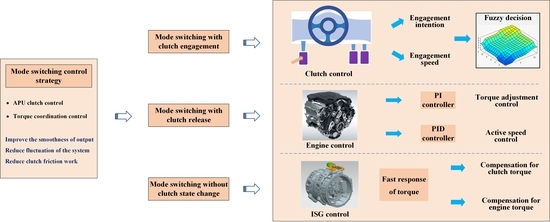
2.2. Control Strategy for Mode Switching Process

The process of mode switching involves control of the clutch, engine, and ISG. Related control strategies are investigated to reduce torque fluctuations and ensure the stability of the mode-switching process.

2.2.1. APU Clutch Control Strategy

It is necessary to comprehensively consider the change of accelerator pedal and power demand of the APU when starting the engine. The control principle is distinctly nonlinear, and the process is complex. Developing an accurate mathematical model for precise expression is too complex and difficult to implement in practice. Therefore, fuzzy control is adopted [28]. The design of the fuzzy controller is shown in Figure 3, which involves fuzzification of input, establishment of an expert knowledge base, formulation of fuzzy inference rules, and clarification of output [29,30].
The engagement process of the APU clutch mainly occurs when the engine is being dragged. Control of the engagement speed is a key aspect of clutch control, which requires a comprehensive consideration of the engagement intention and the speed deviation between the engine and ISG.
Clutch engagement intention can be judged by accelerator pedal stroke σ and its change rate σ ˙ , also called driving intention. If the driver steps on the pedal deep and fast, indicating that the driver wants the APU to connect to the powertrain quickly, the control strategy should focus on dynamics and the engagement speed is fast. Conversely, smoothness is the priority. In the fuzzy controller, the selection of the definition domain and discourse domain and the fuzzification of the input should be considered first. The discourse domain of the accelerator pedal opening is set to {0, 1, 2, 3, 4, 5, 6, 7, 8, 9, 10, 11, 12}, and the fuzzy subset is defined as {S (smaller), RS (small), M (medium), RB (large), B (larger)} 5 levels. Compared with trigonometric and trapezoidal functions, Gaussian functions can provide smoother transitions [31]. The membership function adopts the Gaussian function to ensure the smoothness for control of the pedal. The fuzzification process of the accelerator pedal stroke change rate σ ˙ is similar to σ. To simplify the fuzzy process, the discourse domain of the driver’s clutch engagement intention is set to {0, 1, 2, 3, 4, 5, 6, 7, 8, 9, 10, 11, 12}, and the fuzzy subsets are defined as {XS (very slow), S (slow), M (medium), B (fast), XB (very fast)} 5 levels. In order to ensure rapid judgment, a triangular function is used as the membership function since it provides the best drive performance compared to other functions [32,33]. The Mamdani method is used for fuzzy inference and Centriod is used for defuzzification [34].
The clutch engagement speed is judged by clutch engagement intention and degree during the engine start process. The degree is quantified by the absolute value of the speed difference | Δ ω | between engine speed ω e and ISG speed ω g . If the speed difference is large enough, the engagement speed should be smaller to avoid torque fluctuation. The domain of discourse of | Δ ω | is set to {0, 1, 2, 3, 4, 5, 6, 7, 8, 9, 10, 11, 12} 13 intervals, the fuzzy subset is set as {XS, S, MS (slightly slow), M, MB (slightly fast), B, XB} 7 levels. The speed n z of the motor that controls the clutch is used as the output of the fuzzy controller, its discourse domain is set to {0, 1, 2, 3, 4, 5, 6, 7, 8, 9, 10, 11, 12}, and the fuzzy subset is set to {XS, S, MS, M, MB, B, XB} 7 levels. In order to ensure a fast response, trapezoidal and triangular functions are used as membership functions.
According to the corresponding fuzzy subsets and expert experience, the surface of the fuzzy control is illustrated in Figure 4.
The clutch release bearing engagement speed v c is obtained by converting the product of the speed n z of the motor that controls the clutch and the actuator amplification factor k z . By integrating the speed v c , the increment Δ x of release bearing stroke is obtained, and then the initial stroke x s is added to obtain clutch release bearing stroke x . The equations are as follows:
v c = k z · n z Δ x = v c d t x = Δ x + x s

2.2.2. Torque Coordination Control Strategy

The target truck requires a stable output speed, and the output torque is larger than the demand to ensure the concrete mixer drum works stably at a uniform speed. However, there is a sudden change in torque during the mode-switching process. The torque T c transmitted by the clutch and engine torque deviation between current and target will lead to a disturbance in the APU output, which will result in the fluctuation of the system and even affect the quality of the carried concrete. ISG is used to compensate for this; the control strategy is presented in Figure 5.
During the process of the clutch-driven engine, the torque transmitted by the clutch varies with the stroke of the release bearing. If a compensation strategy is not performed, torque fluctuation will be violent, which will affect the stability of the system.
In the torque adjustment stage, the difference between the engine current and target torque is compensated by the fast response of the ISG before reaching steady-state torque. In this process, the throttle opening of the engine is controlled, and its maximum change rate is set, the variation of engine torque is obtained by integrating it, so as to realize ISG torque compensation. This process is approximately regarded as a quasi-static process, which can make the torque estimation results more reliable.
The engine control strategy can be divided into speed control and torque control, which can suit the need for different mode switching. The control strategy is shown in Figure 6.
Engine speed adjustment is accomplished through throttle opening control. In order to reduce the time of the active speed adjustment process, PID [35,36] control is used. In this stage, engine speed needs to increase rapidly to near the motor speed. If the speed difference decreases to 50 rpm, the clutch is quickly engaged. Since the torque required to keep clutch engagement is small, it can effectively avoid shock. Because the speed is just kept within a certain range without precise synchronization, only PI control is needed, as differential adjustment (D control) is not required to eliminate steady-state deviation.
After the engine’s active speed regulation ends and the clutch is locked, the engine works in a torque control state, and the torque is compensated by the ISG. Torque prediction is difficult because it is non-linear. The throttle opening change rate Δα is limited; by integrating it and superimposing it with the initial value, the estimated throttle opening value can be obtained. The engine speed ω e is matched to the fuel consumption map of the engine to obtain the estimated value of current torque. To track to target torque quickly, the output of PID control is Δα, which can guarantee smoothness while ensuring the continuity rise of torque. The formula for the throttle opening change rate is as follows:
Δ α = m i n Δ α m a x , k p e + k i e d t + k d e ˙
T d e v = T e _ r e q T e _ n
where T d e v is torque deviation; T e _ r e q is engine target torque; T e _ n is engine real-time torque; and k p , k i , k d are the proportional, integral, and differential gain coefficients.

2.3. APU Mode Switching Control Strategy

In the mode-switching process, a reasonable control strategy is formulated to ensure the stability of the output and reduce clutch wear and torque fluctuation. The control strategy is shown in Figure 7.

2.3.1. Mode Switching with Clutch Engagement

During the mode-switching process with clutch engagement, torque deviation can impact the smoothness of the system’s output. It is essential to minimize this deviation. The main factors that influence this deviation are the start point of the engine, the ignition moment, and the clutch’s locked moment.
There are two methods usually adopted to start engines, which are idle ignition and target speed ignition. During idle ignition, there is a sudden change in clutch torque, Δ T c . In target speed ignition, the engine is dragged by the clutch to the target speed of the motor. Then, after the clutch is engaged, it ignites. While Δ T c is smaller in this process, it is still a resistance torque for the engine which can affect the engine’s service life.
Different from the traditional engine idle ignition method, due to the existence of the ISG, the engine is dragged to reach the idle point quickly. Before the engine is ignited, the ISG is in a generator state to provide energy. The mode switching process begins as the clutch starts to engage, then the engine is dragged by the clutch and quickly reaches the idle point for ignition. Subsequently, the engine is then dragged to the target speed by its own output torque T e and the friction torque T c transmitted by the clutch. When the speed difference is less than 50 rpm, the speed is considered to be synchronized, and the clutch is engaged and locked quickly. A clutch in this system can retreat to the critical position between the disengagement and engagement states when the engine is at the idle point. At this time, the clutch does not transmit torque and the engine is decoupled from the ISG, so the improved ignition method can avoid ignition vibration and friction work, prolong the service life of the clutch, and reduce the compensation energy of the ISG. Then, the engine is ignited and regulates its speed. If speed fluctuates within the threshold, the clutch is engaged and locked quickly, and the torque used to keep the clutch engaged is small, hence the sudden change of clutch friction torque Δ T c is also extremely small. The improved engine idle ignition method not only eliminates the engine starter but also improves the success percentage of the engine starting process.
The proposed engine control strategy can improve the mode-switching process effectively. Comparatively, the improved engine idle ignition method mainly benefits the process of engine access, which reduces wear and tear on the clutch. Meanwhile, the engine self-adjustment strategy plays an important role throughout the mode-switching process to improve the smoothness of the system output torque and reduce unnecessary energy consumption.
In summary, the strategy of “improved engine idle ignition + clutch disengaged and re-engaged” is selected for the clutch engagement process. The control strategy is presented in Figure 8.
Stage 1: The clutch is disengaged, and the ISG is in the generator state to provide energy; its torque Tg equals the demanded Tq.
Stage 2: The clutch starts to engage, the clutch eliminates the empty stroke and offsets the resistance torque of the engine starting, and the ISG compensates for the friction torque.
Stage 3: Clutch friction torque increases and the engine speed starts to rise. There is a sudden change in torque which could generate shocks. It is necessary to control the engagement speed to ensure it changes within a feasible region.
Stage 4: Engine speed reaches 800 rpm and ignites. To avoid impact, the clutch returns to a critical state between disengaged and slipped, and the ISG no longer compensates torque. The engine starts and regulates its speed. The clutch remains locked and requires minimal torque; the sudden change of torque is extremely small and will not affect the output of the powertrain.
Stage 5: The clutch is locked and no longer transmits torque. The engine torque is estimated through the throttle opening change rate, and the ISG compensates the engine torque to reduce the torque deviation. The power output of the system can be expressed as:
Torque coordination stage:
T e _ n = T e + k e _ u p d t e = T e _ r e q - T e _ n T g _ n = T g _ r e q + e
Mode switch completion stage:
| e | δ · T e _ r e q T g = T g _ r e q T e = T e _ r e q

2.3.2. Clutch Disengagement Mode Switching Control Strategy

The stability of the torque needs to be considered when the clutch is disengaged. If the exit is too fast and the engine torque has not dropped yet but the load has disappeared, this will lead to a rapid increase in engine speed. If it is slow, the engine turns to a load, and the ISG torque changes quickly, which will cause fluctuations. Hence, a torque coordination strategy is adopted. Figure 9 shows this process.
Stage 1: The APU is still in the combined drive stage, the clutch is engaged, and the engine is used as the power source.
Stage 2: The APU enters the torque coordination stage. The engine controls the torque by limiting the throttle opening change rate, and the ISG compensates the torque. The engine torque change rate is controlled to keep torque variation in the feasible domain. The output of the system is shown in Equation (6):
e = T e _ r e q - T e _ n T e _ n = T e + k e _ d o w n d t T g _ n = e i + T g
Stage 3: Engine torque is within a certain range, the ISG torque reaches target torque, the clutch starts to disengage, and then mode-switching ends. The power output can be expressed as:
T e _ n δ · T e T e = T e _ r e q = 0 T g = T g _ r e q = T q

3. Results and Discussion

In actual working conditions, smoothness, dynamic, and service life need to be considered. Hence, in the mode-switching process, power transmission should ensure stability and reduce shock and vibration. The process is evaluated by friction work, mode switching time, and maximum torque deviation.

3.1. Simulation Verification

The target extended-range vehicle will frequently switch modes to meet the needs of different working conditions. The VCU will send an engine start signal and a clutch engagement signal while the APU needs to be connected to the powertrain. Firstly, it is necessary to determine the clutch state, and then engage the clutch to drag the engine to ignition speed. The simulation analysis is conducted by switching from pure electric mode to combined drive mode.
The results of the engine target speed start process are illustrated in Figure 10. The clutch starts to engage at 0.27 s, then the clutch locks up and the engine ignites at 0.88 s, then the system enters the torque coordination stage. The engine and ISG reach the target torque at 1.09 s, and the mode-switching process ends. The entire process ends in 0.82 s, less than 1 s, and produces a total of 24,051.6 J of friction work; the maximum torque mutation is 391.3 N·m. Figure 11 shows the engine idle start process of “clutch fuzzy control + disengagement + re-engagement”. The clutch starts to engage at 0.27 s. At 0.59 s, the clutch quickly disengages and then the engine injects oil. The clutch retreats to the critical position between the disengagement and engagement state, the engine ignites at 0.68 s, and then the clutch locks up at 0.97 s. The engine and ISG reach the target torque at 1.2 s, and the mode-switching process ends. The entire mode-switching process lasts 0.94 s. The maximum torque deviation from the target during the process is 23.1 N·m, and generates 19,068.4 J of friction work.
During the initial phase of mode switching, the engine torque is negative. This is because the engine is being dragged by the clutch, acting as a drag on the system. The ISG compensates for the friction torque transmitted by the clutch during the engine start process. Once the mode-switching process is complete, the power requirements are met by the engine, while the ISG operates in generator mode with negative torque.
Table 2 shows a comparison of different control strategies. The improved engine idle start strategy is slightly weaker in terms of dynamics. However, the friction work generated during the idle start strategy is reduced by 20.7% compared with the target speed start strategy. At the same time, its maximum torque deviation is only 23.1 N·m, which is greatly reduced.
The APU exits the powertrain when other modes are switched to pure electric. The most complex process of switching from combined drive to pure electric mode is selected for analysis. The results of the clutch disengagement process without torque coordination are illustrated in Figure 12. At 0.3 s, the VCU sends a mode-switching signal. The ISG and engine reach the target torque at 0.35 s and 0.39 s, respectively. At 0.43 s, the engine speed drops to 0, then the clutch disengages and the engine turns off at 0.48 s, and the mode switching process ends. The process completes in 0.18 s, and the maximum torque deviation is 348.2 N·m. Figure 13 shows the results with coordination control. At 0.3 s, the VCU sends a mode-switching signal. The ISG and engine enter the torque coordination stage, then the clutch starts at 0.55 s, the engine turns off at 0.63 s, and the mode-switching process ends. The entire process completes in 0.33 s, and the maximum torque deviation is 19.8 N·m.
A comparison of the simulation results of different strategies is shown in Table 3. Both control strategies can complete the mode switching within the specified time. However, the speed deviation and the maximum torque deviation of the torque coordination strategy are 2 rpm and 19.8 N·m, which are much lower than the uncoordinated control strategy, and the maximum torque deviation is reduced by 94.3%. It makes the output speed and torque stable, which effectively increases the smoothness of the power transmission.
Table 4 summarizes the key characteristics of different mode-switching control strategies. All these methods can effectively accomplish the mode-switching process of the hybrid powertrain, which can complete the mode-switching process in a short period of time and significantly reduce the fluctuation. The rule-based and torque coordination control strategy [25] requires the shortest mode-switching time. In contrast, the control strategy proposed in this research can reduce the speed and torque deviation more effectively.

3.2. Experiment for Mode Switching Control Strategy

Figure 14 shows the experiment platform. The power source adopts a physical engine and ISG, while the load of the concrete mixing drum is emulated by the electric load, and the torque fluctuation of the output can be measured by collecting the torque signal. In the experiment, the signal acquisition frequency is 100 Hz, the engine and ISG speeds are sampled with a resolution of 1 rpm, and the resolution for torque is 0.1 N·m.
When switching from pure electric mode to combined drive mode. Firstly, the system is stabilized in pure electric mode. Then, the VCU sends the pure electric mode start command to the GCU through the APCU. The APCU sends the clutch release command to the CCU. The ISG works in the motor state, and the electric load adopts a constant torque of 250 N·m to emulate the load of the concrete mixing drum. After the speed is stable, the ISG is switched to the torque control mode and the completion signal feeds back to the VCU.
The engine idle start control strategy is used to switch to the combined drive mode. The VCU sends a mode-switching signal and the clutch starts to engage at 0.22 s. At 0.6 s, the engine speed reaches 800 rpm. At 0.7 s, the clutch does not transmit torque, and the engine ignites and enters the speed adjustment state. The engine speed increases to the threshold of lock-up at 0.9 s, then the CCU judges that engine speed reaches the threshold and sends an engagement command to the clutch, which engages quickly and locks at 0.96 s. The system enters the torque coordination stage at 0.98 s. Finally, the engine and ISG reach the target torque at 1.2 s, and the mode-switching process ends. The maximum torque deviation is 48.1 N·m, and a total of 19,563.7 J of friction work is generated. The results are shown in Figure 15.
The experimental results of the clutch engagement process are compared with the simulation results above. The difference in mode switching time between the simulation and experiment is 0.04 s, which is 495.3 J in friction work and 25.0 N·m in maximum torque deviation. The difference between the experiment and simulation is small, and it can be seen from the experiment that the control strategy formulated for the mode-switching process of the extended-range concrete mixer truck can be completed within the specified time, the speed output is stable, and the torque fluctuation is small. Compared with the common engine starting method of ignition at target speed, the clutch generates less friction work, and the energy consumption is lower. It can coordinate the torque of the engine, ISG, and clutch, which solves the problem of torque fluctuation during the mode-switching process with clutch engagement, and prolongs the service life of the APU clutch.
When switching from combined drive mode to pure electric mode, the system is stabilized in the combined drive mode at first. After the clutch disengagement command is issued, the VCU sends the target torque of the engine and ISG to the APCU. The CCU judges after receiving the clutch disengagement command, and feeds back a start signal if the conditions are matched. At 0.3 s, the CCU sends a mode-switching signal. The engine torque reaches the separation threshold at 0.56 s, then the clutch disengages quickly, and the ISG quickly compensates for friction torque. At 0.6 s, the system reaches a stable state and enters a pure electric mode; in this process, the maximum torque deviation is 27.8 N·m. Then, the engine speed is gradually decreased, stabilized to idle speed at 0.77 s, and the engine turns off. At 0.83 s, the engine speed drops to 0, and the mode-switching process ends. The test results are illustrated in Figure 16.
The difference in mode switching time between simulation and experiment is 0.20 s, which is 3 rpm in maximum speed deviation and 8.0 N·m in maximum torque deviation. The experiment results for the clutch disengagement control strategy are similar to the simulation results, and the stability of the output during the mode-switching process can be ensured. The torque fluctuation is greatly reduced compared with the traditional strategy. The problems related to a sudden change in engine speed and the higher torque of the ISG’s instantaneous response are avoided. It ensures the smoothness of the system during mode-switching and extends the service life of the system.

4. Conclusions

This study researches the mode-switching control strategy of the extended-range concrete mixer truck. The developed control strategy includes APU clutch control and torque coordination control among the engine, ISG, and clutch. The ISG global torque compensation strategy is adopted in the whole process. The improved engine ignition method and engine self-adjustment strategy can significantly reduce friction work.
The control strategy of “clutch engagement speed fuzzy control + disengagement + re-engagement + ISG global torque coordination + engine speed self-adjustment” is proposed for the mode-switching process with clutch engagement. The control strategy of “engine torque variation limitation + clutch disengaged quickly + ISG torque compensation” is designed for the mode-switching process with clutch disengagement.
This strategy is verified by simulation and experiment. The results show that the control strategy can increase the smoothness of the system output, significantly reduce the torque fluctuation, and ensure the working stability of the concrete mixing cylinder during the mode-switching process. The control strategy reduces friction work by 20.7% compared with the conventional strategy, which could lead to great improvements in the service life of APU clutches.
Future work will further improve the design of the control strategy, focusing on the optimization of control tune parameters based on swarm intelligence algorithm, and conducting specific analysis of the lifetime improvement of the powertrain.

Author Contributions

S.W.: Writing—original draft, conceptualization. Y.Z.: Methodology, software. Y.H.: Data curation. H.X.: Funding acquisition, supervision, resources, project administration. G.W.: Supervision, resources. F.J.: Writing—review and editing, supervision, resources. All authors have read and agreed to the published version of the manuscript.

Funding

This research was funded by the National Key Research and Development Program of China (Grant No. 2022YFD2001204).

Institutional Review Board Statement

Not applicable.

Informed Consent Statement

Not applicable.

Data Availability Statement

The data presented in this study are available on request from the corresponding author. The authors do not have permission to share data due to privacy restrictions.

Acknowledgments

The authors would like to acknowledge the support of Fengzhi Ruilian Technologies Co., Ltd. of Beijing, China.

Conflicts of Interest

The authors declare no conflicts of interest. Haiming Xie is an employee of Fengzhi Ruilian Technologies Co., Ltd., Beijing, China. The paper reflects the views of the scientists and not the company.

References

  1. Forrest, K.; Kinnon, M.M.; Tarroja, B.; Samuelsen, S. Estimating the technical feasibility of fuel cell and battery electric vehicles for the medium and heavy duty sectors in California. Appl. Energy 2020, 276, 115439. [Google Scholar] [CrossRef]
  2. Ying, H.; Fachao, J.; Haiming, X. Adaptive hierarchical energy management design for a novel hybrid powertrain of concrete truck mixers. J. Power Sources 2021, 509, 230325. [Google Scholar]
  3. Gallikova, D.B.; Caban, J. Maintenance system of semi-trailer and risk priority number. Arch. Automot. Eng.-Arch. Motoryz. 2019, 86, 101–109. [Google Scholar]
  4. Kim, D.M.; Lee, S.G.; Kim, D.K.; Park, M.R.; Lim, M.S. Sizing and optimization process of hybrid electric propulsion system for heavy-duty vehicle based on Gaussian process modeling considering traction motor characteristics. Renew. Sustain. Energy Rev. 2022, 161, 112286. [Google Scholar] [CrossRef]
  5. Skrzek, T.; Rucki, M.; Górski, K.; Matijošius, J.; Barta, D.; Caban, J.; Zarajczyk, J. Repeatability of High-Pressure Measurement in a Diesel Engine Test Bed. Sensors 2020, 20, 3478. [Google Scholar] [CrossRef]
  6. Chehrmonavari, H.; Kakaee, A.; Hosseini, S.E.; Desid-eri, U.; Tsatsaronis, G.; Floerchinger, G.; Braun, R.; Paykani, A. Hybridizing solid oxide fuel cells with internal combustion engines for power and propulsion systems: A review. Renew. Sustain. Energy Rev. 2023, 171, 112982. [Google Scholar] [CrossRef]
  7. Zhang, X.; Wu, Z.X.; Hu, X.S.; Qian, W.; Li, Z. Trajectory Optimization-Based Auxiliary Power Unit Control Strategy for an Extended Range Electric Vehicle. IEEE Trans. Veh. Technol. 2017, 66, 10866–10874. [Google Scholar] [CrossRef]
  8. Huang, Y.; Wang, S.L.; Li, K.; Fan, Z.W.; Xie, H.M.; Jiang, F.C. Multi-parameter adaptive online energy management strategy for concrete truck mixers with a novel hybrid powertrain considering vehicle mass. Energy 2023, 277, 127700. [Google Scholar] [CrossRef]
  9. Zhou, S.L.; Walker, P.; Tian, Y.; Zhang, N. Mode switching analysis and control for a parallel hydraulic hybrid vehicle. Veh. Syst. Dyn. 2021, 59, 928–948. [Google Scholar] [CrossRef]
  10. Yun, S.; Lee, K.; Yi, K. Development of a power management strategy to minimize the fuel consumption of a heavy-duty series hybrid electric vehicle. J. Mech. Sci. Technol. 2015, 29, 4399–4406. [Google Scholar] [CrossRef]
  11. Hong, J.L.; Gao, B.Z.; Yue, H.Q.; Chen, H. Dry Clutch Control of Two-Speed Electric Vehicles by Using an Optimal Control Scheme with Persistent Time-Varying Disturbance Rejection. IEEE Trans. Transp. Electrif. 2021, 7, 2034–2046. [Google Scholar] [CrossRef]
  12. Xiao, B.; Ruan, J.; Yang, W.; Walker, P.D.; Zhang, N. A review of pivotal energy management strategies for extended range electric vehicles. Renew. Sustain. Energy Rev. 2021, 149, 111194. [Google Scholar] [CrossRef]
  13. Lee, W.; Jeoung, H.; Park, D.; Kim, N. An Adaptive Concept of PMP-Based Control for Saving Operating Costs of Extended-Range Electric Vehicles. IEEE Trans. Veh. Technol. 2019, 68, 11505–11512. [Google Scholar] [CrossRef]
  14. Wang, J.J.; Cai, Y.F.; Chen, L.; Shi, D.H.; Wang, R.C.; Zhu, Z. Review on multi-power sources dynamic coordinated control of hybrid electric vehicle during driving mode transition process. Int. J. Energy Res. 2020, 44, 6128–6148. [Google Scholar] [CrossRef]
  15. Smith, A.; Bucknor, N.; Hong, Y.; He, Y. Controls Development for Clutch-Assisted Engine Starts in a Parallel Hybrid Electric Vehicle. In Proceedings of the SAE 2011 World Congress & Exhibition, Detroit, MI, USA, 12–14 April 2011. [Google Scholar] [CrossRef]
  16. Song, M.; Oh, J.H.; Kim, H. Engine clutch control algorithm during mode change for parallel hybrid electric vehicle. In Proceedings of the Vehicle Power and Propulsion Conference, Seoul, Republic of Korea, 9–12 October 2012. [Google Scholar]
  17. Chiang, C.J.; Chen, Y.C.; Lin, C.Y. Fuzzy sliding mode control for smooth mode changes of a parallel hybrid electric vehicle. In Proceedings of the IEEE International Conference on Control & Automation, Taichung, China, 18–20 June 2014. [Google Scholar]
  18. Oh, J.; Choi, S.B.; Chang, Y.J.; Eo, J.S. Engine clutch torque estimation for parallel-type hybrid electric vehicles. Int. J. Automot. Technol. 2017, 18, 125–135. [Google Scholar] [CrossRef]
  19. Tang, X.L.; Zhang, D.J.; Liu, T.; Khajepour, A.; Yu, H.S.; Wang, H. Research on the energy control of a dual-motor hybrid vehicle during engine start-stop process. Energy 2019, 166, 1181–1193. [Google Scholar] [CrossRef]
  20. Zhou, Z.W.; Guo, R.; Liu, X.Y. A disturbance-compensation-based sliding mode control scheme on mode switching condition for hybrid electric vehicles considering nonlinear backlash and stiffness. J. Vib. Control 2023, 29, 3823–3837. [Google Scholar] [CrossRef]
  21. Xu, X.Y.; Zhao, J.L.; Zhao, J.W.; Shi, K.; Dong, P.; Wang, S.H.; Liu, Y.F.; Guo, W.; Liu, X.W. Comparative study on fuel saving potential of series-parallel hybrid transmission and series hybrid transmission. Energy Convers. Manag. 2022, 252, 114970. [Google Scholar] [CrossRef]
  22. Chen, X.; Peng, D.; Wu, W.; Liu, H.; Zheng, X.J. Active Control of Torsional Vibration during Mode Switching of Hybrid Powertrain Based on Adaptive Model Reference. Machines 2022, 10, 647. [Google Scholar] [CrossRef]
  23. Li, H.Z.; Zhang, G. Design of a versatile test bench for hybrid electric vehicles. In Proceedings of the IEEE Vehicle Power and Propulsion Conference, Harbin, China, 3–5 September 2008. [Google Scholar]
  24. Chasse, A.; Sciarretta, A. Supervisory control of hybrid powertrains: An experimental benchmark of offline optimization and online energy management. Control Eng. Pract. 2011, 19, 1253–1265. [Google Scholar] [CrossRef]
  25. Lin, Y.; Qin, D.; Liu, Y.; Yang, Y. Control strategy for all the mode-switches of hybrid electric vehicle. Adv. Mech. Eng. 2016, 8, 1687814016681233. [Google Scholar] [CrossRef]
  26. Vafaeipour, M.; El Baghdadi, M.; Verbelen, F.; Sergeant, P.; Van Mierlo, J.; Hegazy, O. Experimental Implementation of Power-Split Control Strategies in a Versatile Hardware-in-the-Loop Laboratory Test Bench for Hybrid Electric Vehicles Equipped with Electrical Variable Transmission. Appl. Sci. 2020, 10, 4253. [Google Scholar] [CrossRef]
  27. Song, D.F.; Wu, J.J.; Yang, D.P.; Chen, H.X.; Zeng, X.H. An active multiobjective real-time vibration control algorithm for parallel hybrid electric vehicle. Proc. Inst. Mech. Eng. Part D-J. Automob. Eng. 2023, 237, 21–33. [Google Scholar] [CrossRef]
  28. Zou, K.; Luo, W.; Lu, Z. Real-Time Energy Management Strategy of Hydrogen Fuel Cell Hybrid Electric Vehicles Based on Power Following Strategy–Fuzzy Logic Control Strategy Hybrid Control. World Electr. Veh. J. 2023, 14, 315. [Google Scholar] [CrossRef]
  29. Pan, Y.N.; Li, Q.; Liang, H.J.; Lam, H.K. A Novel Mixed Control Approach for Fuzzy Systems via Membership Functions Online Learning Policy. IEEE Trans. Fuzzy Syst. 2022, 30, 3812–3822. [Google Scholar] [CrossRef]
  30. Aravind, R.V.; Balasubramaniam, P. Membership-Function-Dependent Design of Quantized Fuzzy Sampled-Data Controller for Semi-Markovian Jump Systems with Actuator Faults. IEEE Trans. Fuzzy Syst. 2023, 31, 40–52. [Google Scholar] [CrossRef]
  31. Multani, M.; Ren, J.; Sood, V.K. Fuzzy logic (FL) controlled HVDC system-influence of shape, width & distribution of membership functions (MFs). In Proceedings of the CCECE 2010, Calgary, AB, Canada, 2–5 May 2010; pp. 1–7. [Google Scholar]
  32. Zhao, J.; Bose, B.K. Evaluation of membership functions for fuzzy logic controlled induction motor drive. In Proceedings of the IEEE 2002 28th Annual Conference of the Industrial Electronics Society, IECON 02, Seville, Spain, 5–8 November 2002; pp. 229–234. [Google Scholar]
  33. Prasad, K.A.; Nair, U.; Unnikrishnan, A. Fuzzy sliding mode control of a Permanent Magnet Synchronous Motor with two different fuzzy membership functions. In Proceedings of the 2015 International Conference on Power, Instrumentation, Control and Computing (PICC), Thrissur, India, 9–11 December 2015; pp. 1–6. [Google Scholar]
  34. Moness, M.; Mahmoud, D.; Hussein, A. Real-time Mamdani-like fuzzy and fusion-based fuzzy controllers for balancing two-wheeled inverted pendulum. J. Ambient. Intell. Humaniz. Comput. 2020, 13, 3577–3593. [Google Scholar] [CrossRef]
  35. Chu, D.F.; Li, H.R.; Zhao, C.Y.; Zhou, T.Q. Trajectory Tracking of Autonomous Vehicle Based on Model Predictive Control with PID Feedback. IEEE Trans. Intell. Transp. Syst. 2023, 24, 2239–2250. [Google Scholar] [CrossRef]
  36. Shamseldin, M.A. Design of Auto-Tuning Nonlinear PID Tracking Speed Control for Electric Vehicle with Uncertainty Consideration. World Electr. Veh. J. 2023, 14, 78. [Google Scholar] [CrossRef]
Figure 1. The powertrain of the extended-range concrete mixer truck.
Wevj 15 00040 g001
Figure 2. Control system of the extended-range concrete mixer truck.
Wevj 15 00040 g002
Figure 3. Fuzzy control process.
Wevj 15 00040 g003
Figure 4. Fuzzy control surface. (a) Fuzzy rule control surface for driving intention; (b) Fuzzy control for motor speed that controls the clutch.
Wevj 15 00040 g004
Figure 5. ISG torque compensation strategy. (a) ISG compensation strategy for clutch torque; (b) ISG compensation strategy for engine torque; (c) Engine fuel consumption map.
Wevj 15 00040 g005aWevj 15 00040 g005b
Figure 6. Engine control strategy. (a) Engine active speed control; (b) Engine torque adjustment control.
Wevj 15 00040 g006
Figure 7. APU clutch mode switching control strategy.
Wevj 15 00040 g007
Figure 8. Control flow chart for clutch engagement process.
Wevj 15 00040 g008
Figure 9. Control flow chart for clutch disengagement process.
Wevj 15 00040 g009
Figure 10. Results of engine target speed start process. (a) Torque; (b) Speed; (c) Friction work; (d) Torque deviation.
Wevj 15 00040 g010
Figure 11. Results of engine idle start process. (a) Torque; (b) Speed; (c) Friction work; (d) Torque deviation.
Wevj 15 00040 g011
Figure 12. Results of the clutch disengagement process without torque coordination control. (a) Torque; (b) Speed; (c) Torque deviation.
Wevj 15 00040 g012
Figure 13. Results of the clutch disengagement process with torque coordination control. (a) Torque; (b) Speed; (c) Torque deviation.
Wevj 15 00040 g013
Figure 14. Experiment platform for the range extender. (a) Structure diagram; (b) Experiment platform.
Wevj 15 00040 g014
Figure 15. Experiment results for clutch engagement process. (a) Torque; (b) Speed; (c) Friction work; (d) Torque deviation.
Wevj 15 00040 g015
Figure 16. Experiment results for clutch disengagement process. (a) Torque; (b) Speed; (c) Torque deviation.
Wevj 15 00040 g016
Table 1. Basic parameters for the powertrain of the concrete mixer truck.
ItemParametersValues
Vehicle massCurb mass15,000 kg
Gross mass40,000 kg
Transmission systemEfficiency0.93
BatteryCapacity300 Ah
EngineMaximum power125 kW
Maximum speed2800 rpm
MotorMaximum power350 kW
Maximum speed3000 rpm
ISGMaximum power130 kW
Maximum speed3000 rpm
Table 2. Comparison of clutch engagement process control strategy.
Control StrategySwitching Time (s)Friction Work (J)Max Torque Deviation (N·m)
Engine idle start
process
0.9419,068.423.1
Engine target
speed start
0.8224,051.6391.3
Table 3. Comparison of clutch disengagement process control strategies.
Control StrategySwitching Time
(s)
Max Speed Deviation
(rpm)
Max Torque Deviation
(N·m)
Torque coordination control0.33219.8
Without torque
coordinate control
0.1828348.2
Table 4. Comparison of different mode-switching control strategies.
MethodSwitching Time
(s)
Decrease in Speed
Deviation
Decrease in Torque
Deviation
The proposed mode-switching strategy0.9892.6%94.3%
Active control of torsional vibration [22]1.279.6%77.4%
Rule-based control strategy [25]0.571.7%
(Decrease in maximum impact)
68.4%
Disclaimer/Publisher’s Note: The statements, opinions and data contained in all publications are solely those of the individual author(s) and contributor(s) and not of MDPI and/or the editor(s). MDPI and/or the editor(s) disclaim responsibility for any injury to people or property resulting from any ideas, methods, instructions or products referred to in the content.

