Article

Combined Electromagnetic and Mechanical Design Optimization of Interior Permanent Magnet Rotors for Electric Vehicle Drivetrains

Department of Electronic and Electrical Engineering, University of Sheffield, Sheffield S1 3JD, UK
*
Author to whom correspondence should be addressed.
World Electr. Veh. J. 2024, 15(1), 4; https://doi.org/10.3390/wevj15010004 (registering DOI)
Submission received: 20 October 2023 / Revised: 13 November 2023 / Accepted: 17 November 2023 / Published: 21 December 2023

Abstract

:
In many high-speed electrical machines, centrifugal forces within the rotor can be first-order constraints on electromagnetic optimization. This can be particularly acute in interior permanent magnet (IPM) machines in which magnets are usually retained entirely by the rotor core with no additional mechanical containment. This study investigates the nature of the trade-off between mechanical and electromagnetic requirements within the context of an eight-pole, 100 kW IPM machine with a base speed of 4000 rpm and an extended speed range up to 12,000 rpm. A series of mechanical and electromagnetic models are used to estimate the level of shaft interference, mechanical stress in critical regions of the rotor and the impact of various features and dimensions within the machine on electromagnetic torque. A systematic exploration of the design space is undertaken for rotor diameters from 120 mm to 180 mm, with optimal designs in terms of torque per unit length established at each diameter while meeting the constraints imposed on mechanical stress. The final preferred design has a rotor of 165 mm and an axial length of 103 mm long with a fractional slot winding in a 30-slot stator. The overall machine has an active mass of 42.3 kg, which corresponds to ~2.4 kW/kg. This paper describes the optimization study in detail and draws on the results to explore the nature of the design trade-offs in such rotors and the impact of core properties.

1. Introduction

Permanent magnet (PM) machines have become the favored machine technology for the vast majority of electric vehicle (EV) drivetrains due to their combination of superior power density, power factor and efficiency at rated power when compared to competing machine technologies [1]. In permanent magnet machines whose rotors are not subjected to large centrifugal loads, there is a generally accepted maxim that torque density tends to improve with increasing rotor diameter [2]. However, in some applications, the combination of diameter and rotational speed results in large centrifugal loads within the rotor. There is no definitive threshold beyond which machines are regarded as high-speed machines, although peripheral linear speeds beyond 100 m/s or so have been proposed as a useful definition [3]. In most high-speed machines, the mechanical loads may be sufficient to have a marked impact on the mechanical design of the rotor, and, hence, there is often a need to trade off some electromagnetic performance to ensure a robust rotor mechanical design. Moreover, the mechanical load tends to push the optimum aspect ratio to achieve a given torque rating towards longer- and smaller-diameter machines [2].
Interior permanent magnet (IPM) machines in which individual magnet poles are fully enclosed within matching apertures in the rotor core have been adopted in many EV drivetrains and, indeed, are the preferred rotor topology in most mainstream EV applications other than very-high-speed machines in niche vehicle applications. This is due to a combination of their ability to be operated readily in so-called ‘field-weakening’ mode, the scope to produce saliency torque to supplement the PM excitation torque and the scope for an IPM rotor core to provide the sole mechanical containment and support for the rotor PMs, thus simplifying rotor manufacture. If the centrifugal loading produced through a combination of the self-loading of the core and dead-weight loading from the PMs can be accommodated within the stress limits of the rotor cores, then there is no requirement to employ a separate sleeve or can on the rotor [4]. Published design studies have shown that V-shaped IPM topologies tend to have superior performance compared to other IPM topologies, require less magnet volume and can withstand higher mechanical stresses [5,6,7].
However, to exploit the self-containing capability of IPM rotor cores, it may prove necessary to thicken up critical regions of the rotor core to take the centrifugal load at acceptable levels of localized stress. The narrow regions adjacent to the airgap that close off the apertures that contain the PMs tend to be the regions of the highest mechanical stress and that tend to require thickening up to accommodate high-speed operation. However, these are also the regions that tend to promote the leakage of the PM flux within the rotor. However, thickening up these regions to accommodate centrifugal loading tends to have an adverse effect on the magnitude of the airgap flux density and, hence, the torque capability. Hence, for a given combination of torque and speed, there is likely to be an optimum rotor size and aspect ratio that yields the maximum torque density. This study seeks to investigate this design trade-off in IPM machines through the electromagnetic and mechanical optimization of the rotor of an IPM machine. Although it is focused on a particular performance specification, many of the trade-offs involved have a more generic utility.

2. Design Study Baseline Machine Dimensions and Performance

The performance specifications of the IPM machine considered in this study are representative of a traction machine for a medium-sized, mass-market passenger vehicle, and they are summarized in Table 1.
The rotor geometry adopted is based on a single-layer V-shaped arrangement of magnets, as shown in Figure 1. The individual geometry of the magnet pieces is profiled at their outer edges, as shown in Figure 2, in an attempt to reduce mechanical stress concentrations in the surrounding rotor core. It is recognized that this intricate shaping of the magnets has cost implications, but as shown later in this paper, this profiling yields dividends in terms of allowing the rotor core to be shaped to reduce leakage flux within the rotor, in turn enhancing torque. The stator and rotor core are NO20 silicon–iron, and the rotor permanent magnets are 35MGOe NdFeB grade with a room temperature remanence of 1.22 T.
The baseline machine design has an 8-pole rotor and a 30-slot stator core, which is equipped with a fractional slot winding with the coil arrangement shown in Figure 1. The machine cross-section in Figure 1 is scaled for various rotor diameters in a systematic manner, which maintains the proportions shown in Figure 1. Table 2 shows the leading dimensions of the machine normalized by the rotor diameter. The normalized dimensions shown correspond to a so-called split ratio [8] of 0.64, i.e., the ratio of the rotor outer diameter to the stator outer diameter.
In all cases, the stator tooth spans an angle of 7° at the airgap, and the angle between the magnets that make up one pole (defined as β in Figure 2) is 130°. The three radii on the magnet corners shown in Figure 2 are set to 1 mm for the 135 mm diameter machine and then scaled in accordance with the method for other machine dimensions, with a maximum radius of 1.3 mm in the case of the 180 mm diameter rotor. The only modification to a pure scaling of the machine cross-section with the rotor diameter is a small adjustment to the stator bore diameter to maintain the same 0.5 mm mechanical airgap in all designs.

3. Material Properties and Mechanical Properties

3.1. Magnetic Material Properties

The microstructure and processing of most electrical steels are optimized almost entirely to achieve the highest magnetic functional properties. As a result, the mechanical properties of electrical steels tend to be modest in comparison to those of steels or other alloys optimized solely for mechanical behavior. There are often multiple grades within the product range of a given manufacturer, and they offer some trade-off between mechanical and magnetic properties [9]. Although, in principle, this offers the opportunity to employ different grades of electrical steels in the rotor and stator cores, the utilization of electrical steels is generally poor when a single-piece stator alone is taken out of the starting strip of the material, with the region within the bore of the stator core being discarded as scrap. Improved utilization of the starting strip can be realized by taking out the rotor core from within the bore of the stator core. This may result in the use of a grade of electrical steel for the rotor core that has some trade-off in mechanical and magnetic properties to balance the different demands of the stator and rotor cores.
This study is based on NO20-1200H core material, which is a specific grade of 0.2 mm thick, non-oriented silicon–iron. This is not a grade developed specifically for its mechanical properties, but by virtue of being 0.2 mm thick, it is often adopted as a mainstream option for the stators of higher-speed machines. The manufacturer quoted that the minimum 0.2% yield strength is 400 MPa in the rolling direction, which increases by ~2% in the transverse direction. One important consideration is the margin adopted between the design stress limit and the material yield stress. Setting this margin requires consideration of factors such as fatigue, temperature cycling and aging effects. Typically, a design stress limit of 50–60% of the manufacture-quoted yield strength would be adopted, although with extensive in-service experience and operational data, this percentage might be increased. Adopting a design stress limit that is 60% of the 0.2% yield strength of NO20 gives rise to a design stress of 240 MPa for this optimization study. The key mechanical properties adopted for the NO20 rotor core and the NdFeB rotor magnets are summarized in Table 3.

3.2. Influence of Interference Fitting of Shaft

Interference fitting is widely used in powertrain components as a straightforward, reliable and low-cost means of securing shafts into hubs and cores [10]. The degree of interference employed must be carefully specified to ensure that the radial pressure exerted on the shaft by the rotor core is sufficient to transmit the electromagnetic torque. This condition must be met over the full speed and temperature range encountered in service and is usually set with a significant spare margin. However, setting the level of interference must also take account of the fact that the interference fit at the bore of the rotor core increase the stress in the remainder of the rotor core. Hence, it is important not to over-specify the interference.
A useful estimate of the minimum interference required between the shaft and the rotor core can be established from a simplified model in which the rotor is represented as a solid annulus of uniform density. For a rotating solid annulus representation of the rotor core with outer radius r c o and inner radius r c i , the radial growth at the inner radius for a rotor of density ρ , Young’s modulus E and Poisson’s ratio ν when rotating at an angular velocity of ω is given by Equation (1) from [11]. For the smallest and largest NO20 rotor cores considered in this study, viz., 120 mm and 180 mm outer diameters, the predicted radial growths of a bore that accommodates a 25 mm shaft are 2.2 µm and 4.9 µm, respectively, at a rated speed of 12,000 rpm.
r c i = ρ ω 2 r c i 4 E 3 + υ r c o 2 + ( 1 ν ) r c i 2
Similarly for the shaft, the change in its outer radius when rotating at an angular velocity of ω is given by
r s o = ρ ω 2 r s o 4 E 1 υ r s o 2
For a 25 mm diameter steel shaft (with a modulus of 200 GPa and a density of 7800 kg/m3), the resulting radial growth at 12,000 rpm is a mere 0.02 µm. The difference in radial growth between the shaft and the bore of the rotor core in effect reduces the net interference at the maximum speed from the interference set at standstill. The interference at standstill must be sufficient to accommodate the differential radial growth of the rotor core while still maintaining sufficient inward radial pressure on the shaft to transmit the rated torque with an appropriate safety margin. A well-established method for calculating the contact pressure and resulting hoop stresses between interfering concentric cylinders is given in [10]. For the case of a solid shaft, the interference, δ i , required to achieve a contact pressure between the shaft and the rotor core of P i is given from [10] by
δ i = P i r c i r c i 2 1 + υ c E c r c o 2 + r c i 2 + r c o 2 1 + υ c E c r c o 2 r c i 2 r c i 2 1 + υ s E s r c i 2
Taking the case of a 180 mm outer diameter rotor and assuming, for the time being, an axial length of 100 mm (an estimate of which can be obtained on an a priori basis for simple torque-sizing equations), the radial pressure required to transmit the rated torque of 239 Nm assuming a worst-case coefficient of friction of 0.2 between the shaft and the core is 12.2 MPa. This, in turn, requires a minimum net radial interference of 1.5 µm at the maximum speed, which, in turn, requires a standstill interference of 6.4 µm to allow for the 4.9 µm radial growth at 12,000 rpm. Allowing a safety factor of 2 on the interference yields a diametrical interference of 25 µm. This, in turn, generates a maximum radial pressure of 99.7 MPa at standstill. The resulting hoop stress in the rotor core at the inner bore is hence given by
σ θ , c o r e = P i r c o 2 + r c i 2 r c o 2 r c i 2
This results in a maximum hoop stress within the core at standstill of 103.6 MPa, which is well within the material design limit. Although cautious in terms of the safety margin on the interference required to transmit the torque, a diametrical interference of 25 µm between the core and the shaft is fixed for the remainder of this investigation.

3.3. Modeling

Structural finite element calculations were performed using a linear elastic model (i.e., fixed modulus) within the ANSYS environment. The contact faces between the individual magnet pieces and the rotor core were represented as frictional contacts with a coefficient of friction of 0.2. A very light interference fit between the magnet and rotor core of 2 µm was employed, and the interference fit between the rotor core and the shaft was set to 25 µm for all rotor diameter combinations.
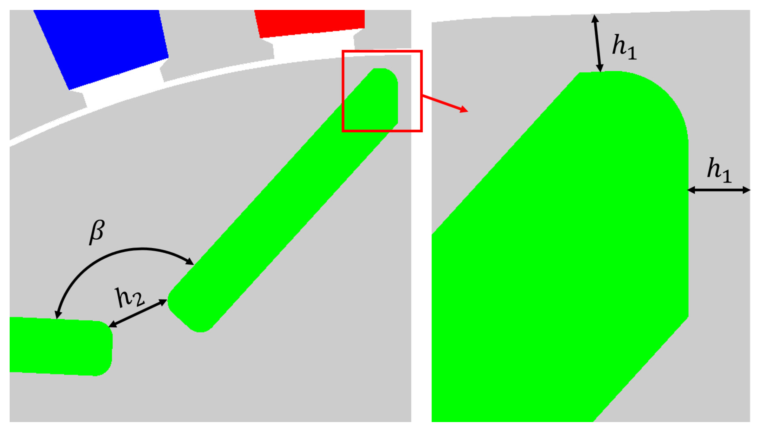
A series of rotor outer diameters between 120 mm and 180 mm (in 15 mm increments) were considered. For each rotor diameter, a total of 154 designs were modeled comprising all-inclusive combinations of designs with h1 values from 0.4 mm to 2.5 mm in 0.1 mm steps and 
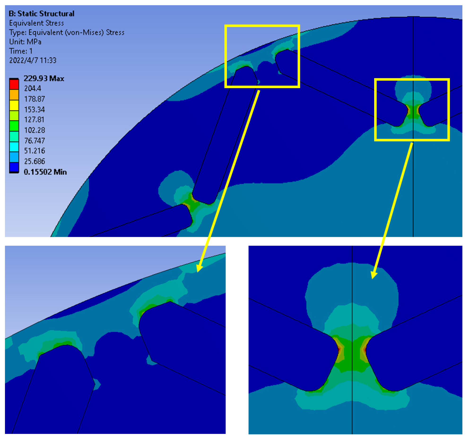
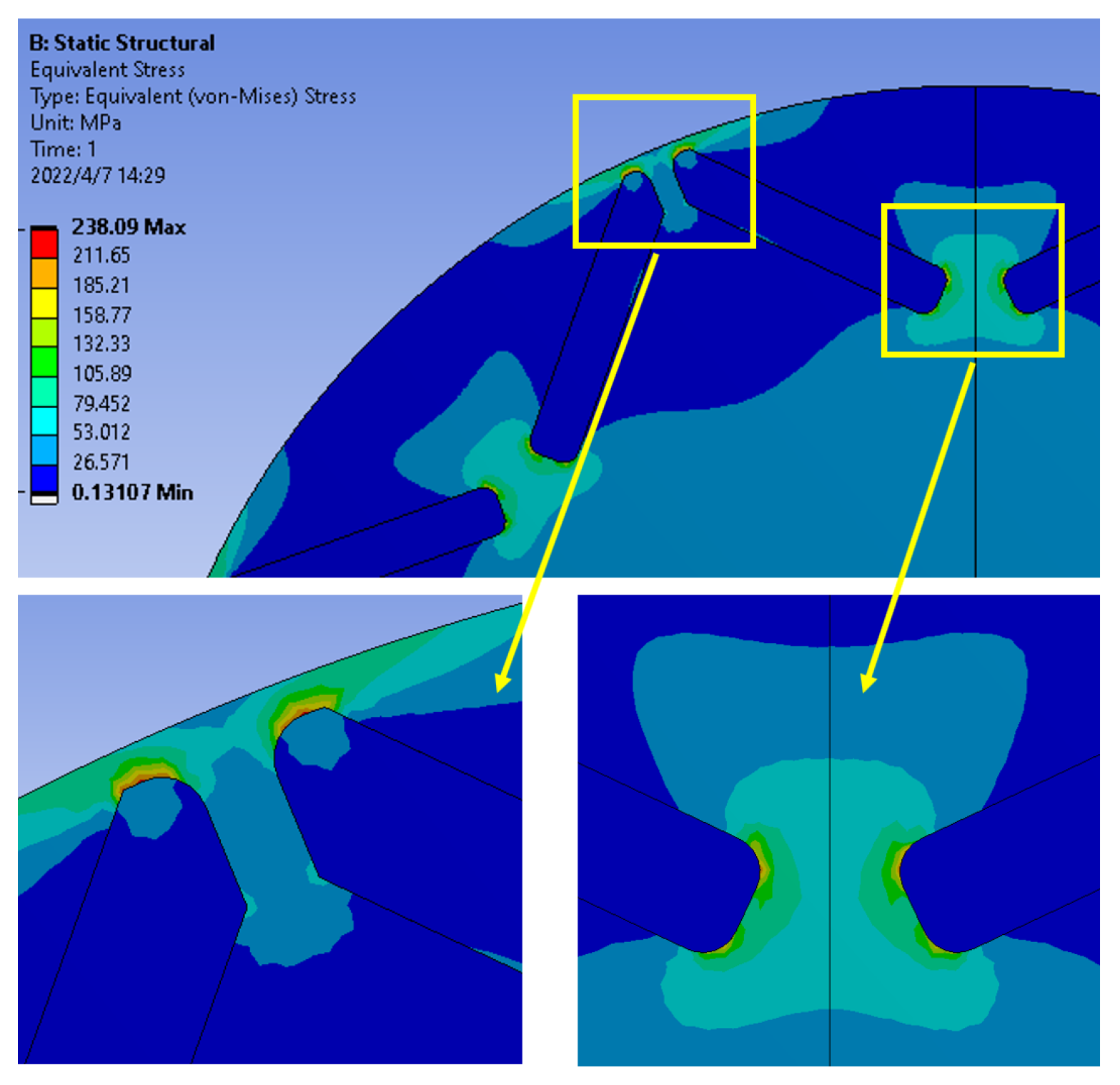
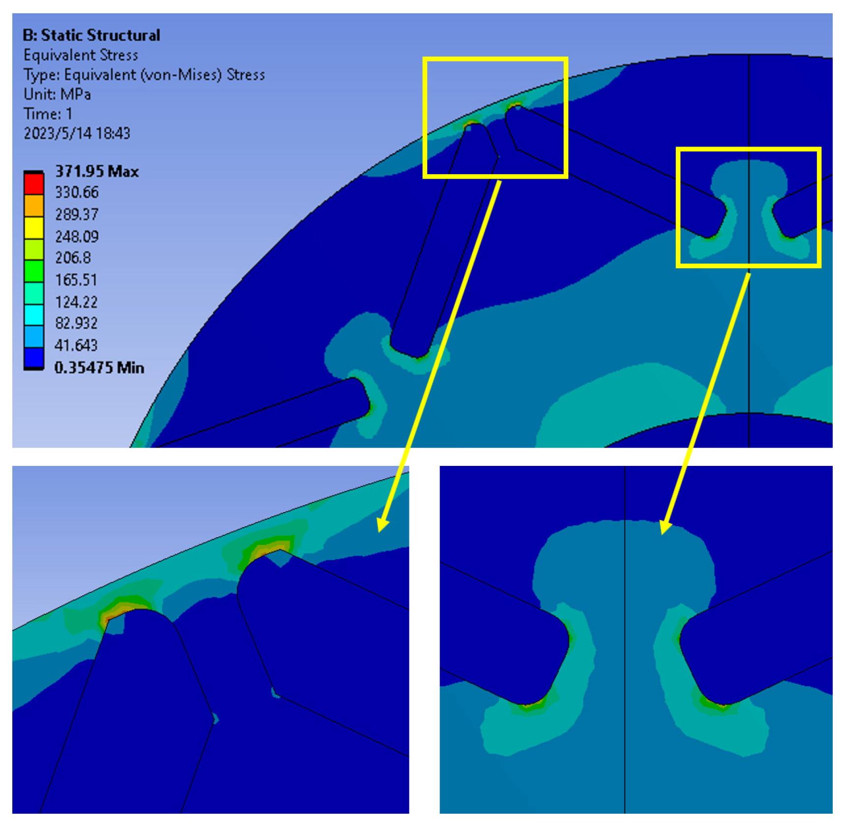
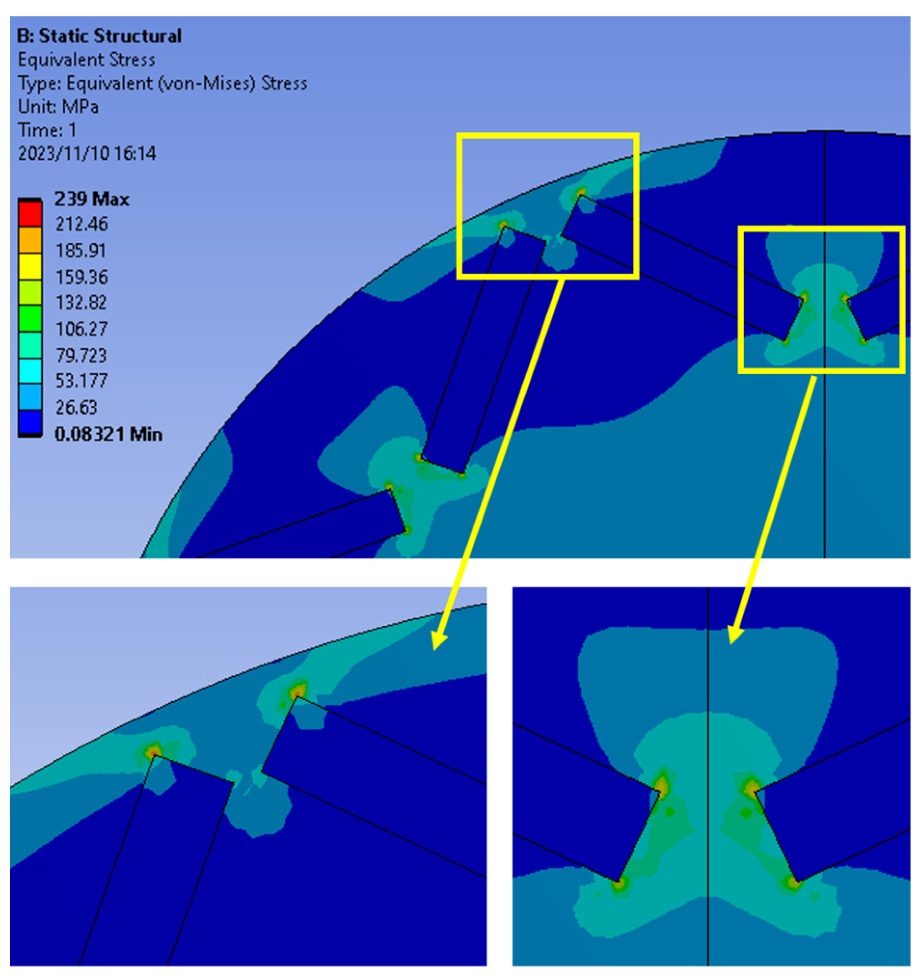
h2 values from 0.8 mm to 2 mm in 0.2 mm steps. An example of the resulting von Mises stress distribution in the vicinity of the rotor magnets is shown in Figure 3; this case is a 135 mm diameter rotor at a maximum speed of 12,000 rpm with h1 = 2 mm and h2 = 1 mm. Although much of the rotor operates at stress levels below 50 MPa, as would be expected, there are regions of stress concentration at the outer tips of the magnets and in the gap between the innermost regions of the magnets. In this case, the peak localized stress is 230 MPa, which is just within the design stress limit of 240 MPa set for the NO20 rotor material.
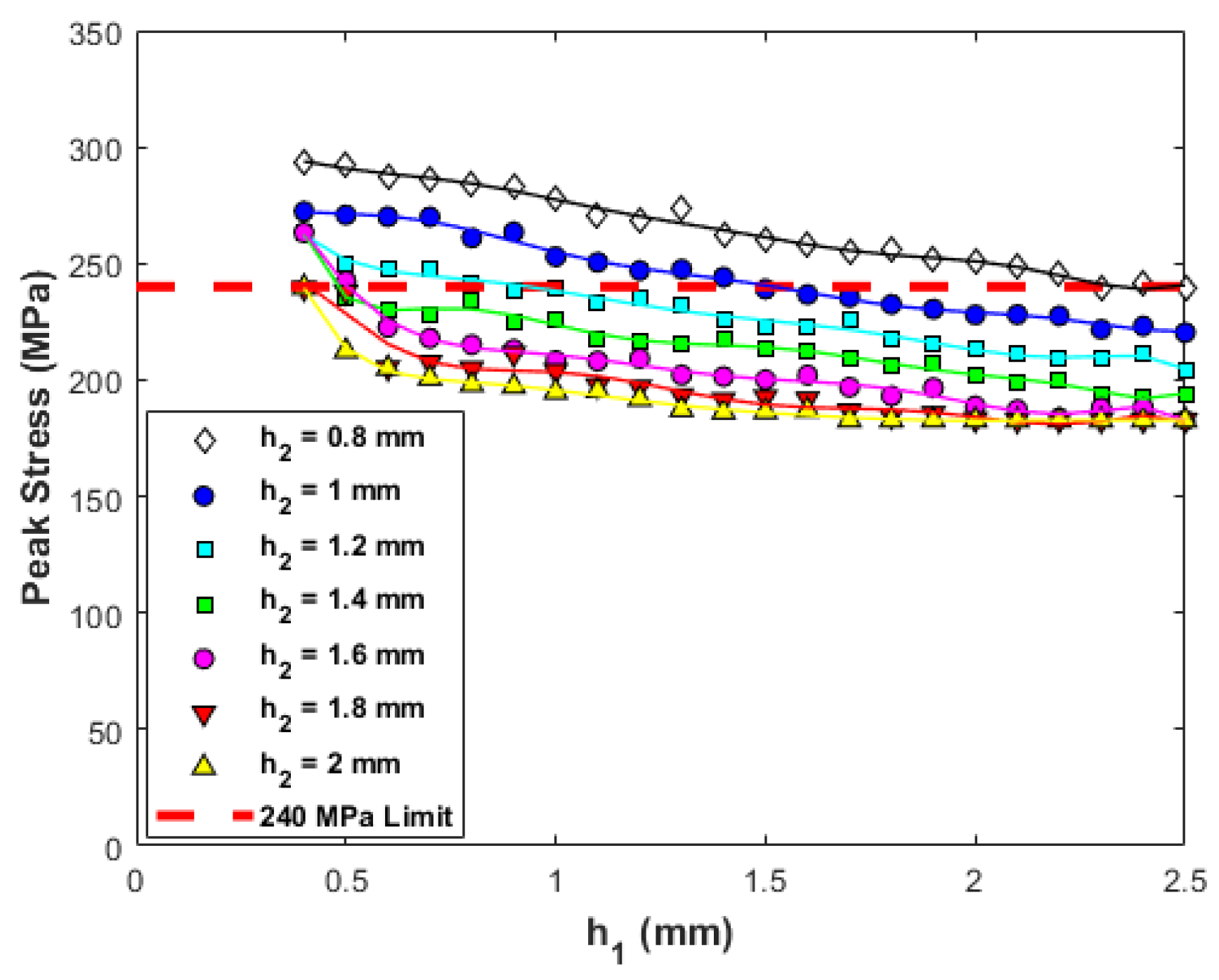
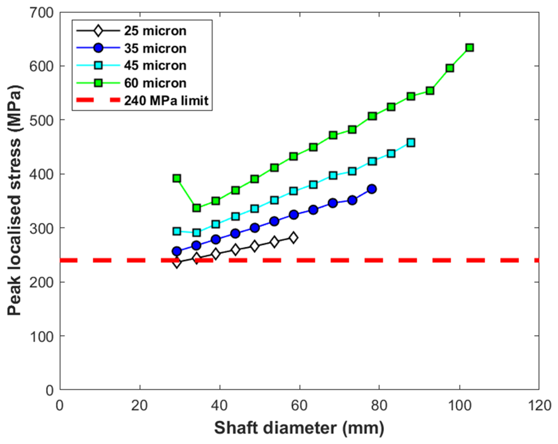
Taking again the example of the 135 mm diameter rotor, the variation in the maximum predicted localized stress at 12,000 rpm as a function of h1 and h2 for the 154 designs considered is shown in Figure 4. In this case, 40 combinations of h1 and h2 result in localized stress levels greater than the 240 MPa design stress limit set for this study.
Having established the combinations of h1 and h2 that yield viable designs from a mechanical stress threshold perspective, the electromagnetic torque is calculated using a two-dimensional, magneto-static, non-linear finite element analysis for the specific case of a stator rms current density of 10 A/mm2 (at an assumed slot fill factor of 0.45) with a current advance angle of 45° (electrical).
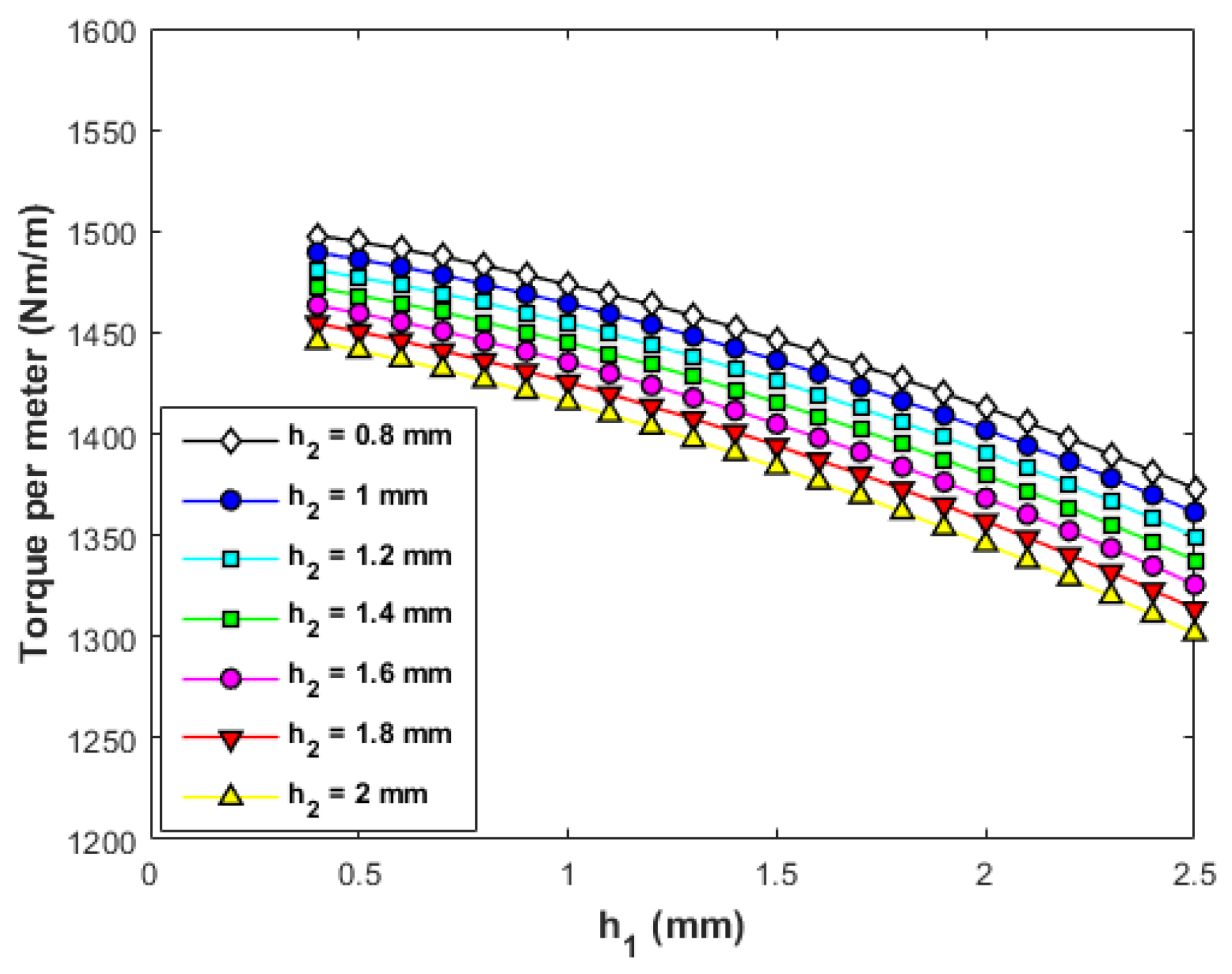
The resulting average torque per unit length values calculated for the 154 design combinations with a 135 mm diameter rotor are shown in Figure 5. Although 40 of these combinations are not viable mechanically, the torques that they produce are included to demonstrate the torque penalty that results from a design stress limit of 240 MPa. For this 135 mm diameter rotor, the highest predicted torque per unit length is 1498 Nm/m for the smallest combination of h1 (0.4 mm) and h2 (0.8 mm), although this results in a peak localized stress of 290 MPa. The highest predicted torque per unit length for a design that also results in a von Mises stress that falls within the design limit of 240 MPa is 1468 Nm/m, which is achieved for an h1 value of 0.5 mm and an h2 value of 1.4 mm. Scaling this torque per unit length to meet the torque specification set out in Table 1 yields an axial length of 162 mm for this rotor diameter of 135 mm, in turn yielding a predicted mass for this design, including an estimate of end-winding mass of 50.6 kg, which corresponds to ~2 kW/kg.
Repeating this process to establish the optimal designs for all the rotor outer diameters between 120 mm and 180 mm yields the series of designs summarized in Table 4, which exhibit the maximum torque per unit length within a peak design stress limit of 240 MPa at 12,000 rpm. The axial lengths of the stator and rotor cores of these designs are all scaled to produce a rated torque of 239 Nm at a stator rms current density of 10 A/mm2 (at an assumed slot fill factor of 0.45).
As would be expected, increasing the rotor diameter beyond 120 mm requires larger values of h1 and h2 to maintain the localized stress within the rotor below the 240 MPa limit. Thickening up the rotor core beyond the end of the magnets tends to promote increased leakage flux within the rotor. It is apparent from the results presented in Table 4 that there is an optimum rotor diameter of 165 mm, albeit that this is specific to this combination of rotational speed, rotor core maximum stress limit, machine split ratio and current density constraints. Without mechanical stress considerations, the torque density tends to continually increase with increasing rotor diameter because of the nature of scaling with the diameter of the electric loading (Ampere turns per unit of airgap periphery). There is a further tendency for the predicted torque density to increase with diameter due to the limitations of two-dimensional finite element modeling. A two-dimensional finite element electromagnetic analysis does not account for the influence of end effects in short-axial-length machines and, hence, tends to overestimate the torque produced by machines with short axial lengths relative to diameters. The presence of an optimum in Table 4 is a consequence of the electromagnetic penalty, which is increasingly incurred with the need to thicken up the regions of the rotor core adjacent to the airgap to ensure that the entire rotor core remains with the specified design mechanical stress.
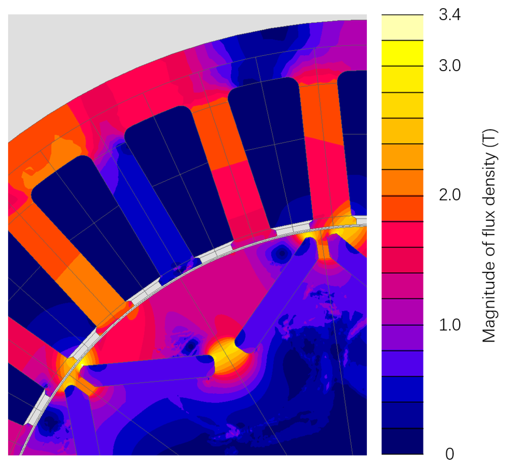
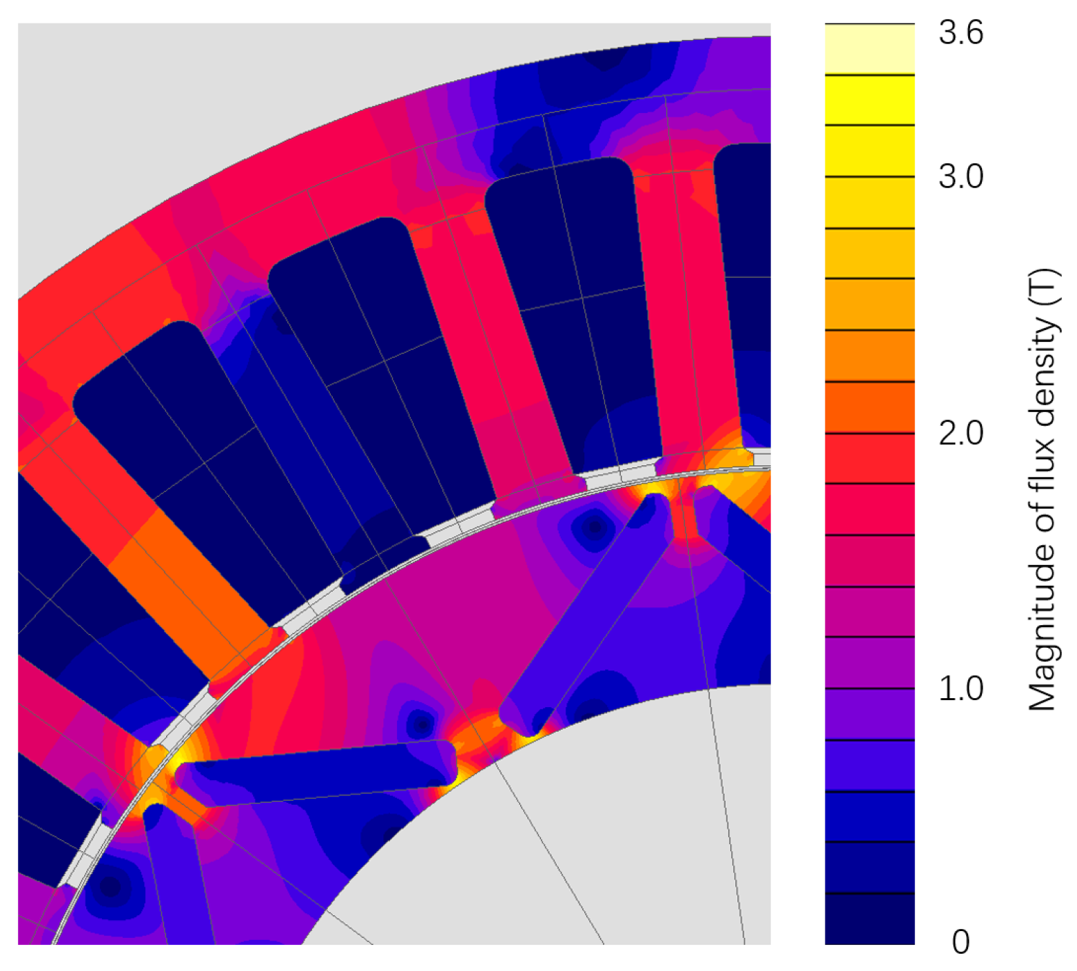
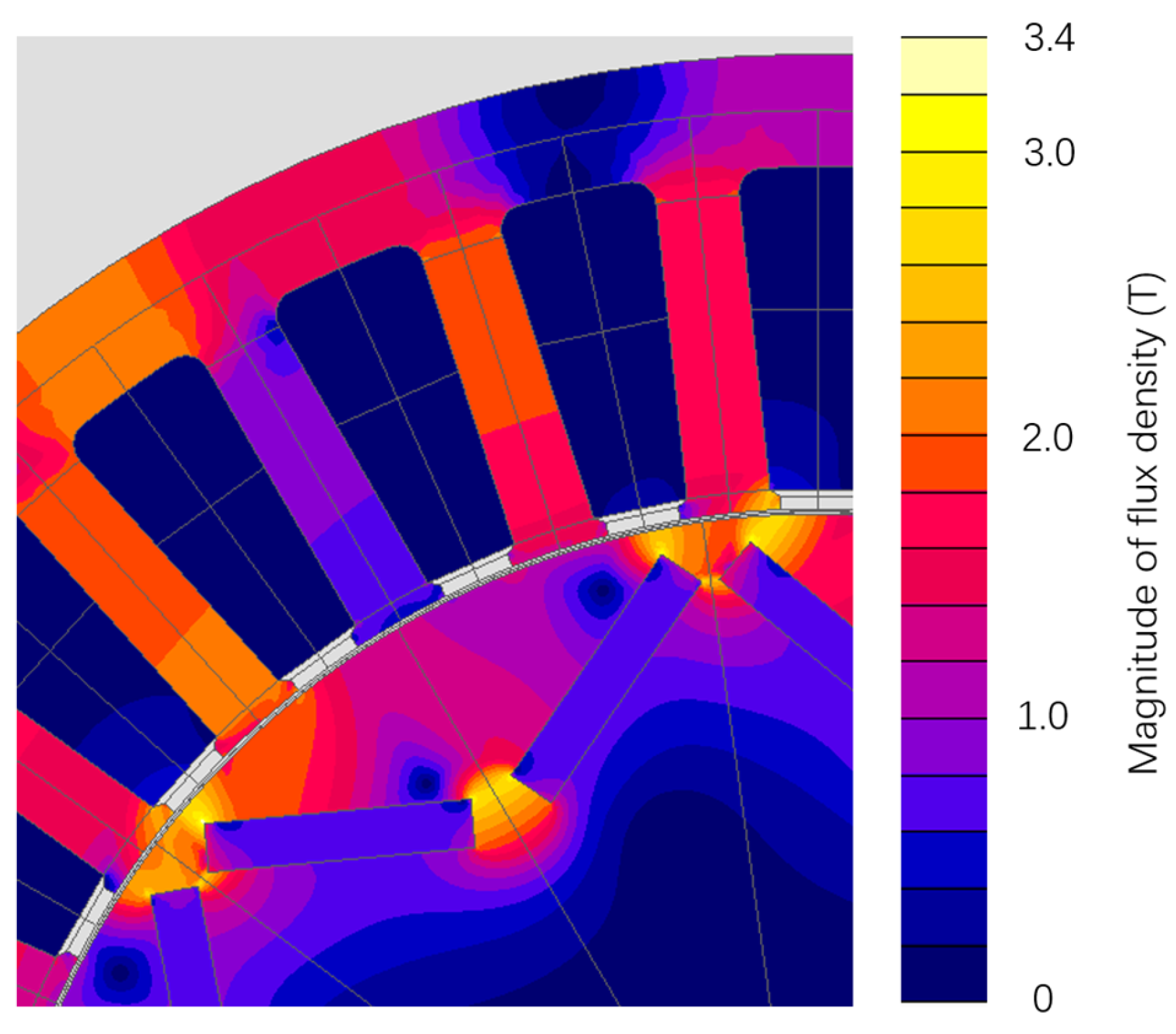
Figure 6 shows a predicted flux density distribution in the rotor and stator cores of this 165 mm diameter design at the rated torque, while Figure 7 shows a close-up of the von Mises stress distribution in the region around the magnet poles at 12,000 rpm. As is apparent, there is significant magnetic saturation both in regions adjacent to the airgap near the magnet tips and in the regions between the pair of magnets that make up one pole, with peak flux densities of up to ~3.4 T. This saturation plays an important role in limiting the magnet leakage flux within the rotor core, which would otherwise further diminish the airgap flux density. This illustrates the importance of modeling the behavior beyond saturation accurately, as this can have a significant bearing on torque in this machine, even at modest electric loading. In this regard, the representation of the magnetization characteristics is best suited to a semi-analytical model in which saturation is enforced mathematically rather than extrapolated from a series of discrete data points.

4. Influence of Hub Diameter

The rotor designs considered up to this point are all based on scaling the cross-section of the rotor according to a fixed shaft-to-rotor diameter ratio of 0.185. This results in a range of shaft diameters between 22.2 mm and 33.3 mm for the range of rotor outer diameters considered. The remainder of the rotor cross-section is occupied entirely by the rotor core and magnets. From an electromagnetic point of view, much of the inner regions of the rotor need not be magnetic, and, indeed, the nature of the field distribution with an IPM is such that this large region of core within the magnets can promote leakage flux. Hence, employing a non-magnetic and lightweight hub to span the region between the shaft and a slimmed down rotor core will yield dividends in terms of a reduced mass, and it may also yield some electromagnetic benefits. Taking the 165 mm rotor diameter design in Table 4, which offers the highest torque density of all the rotor diameters considered, a series of electromagnetic finite element predictions of average torque are performed with gradually increasing diameter of the non-magnetic hub radius, which, in electromagnetic terms, increases the bore diameter of the rotor core. The non-magnetic hub diameter is limited by the presence of the V-shaped arrangement of the magnets. For the particular arrangement adopted, the inner edges of the magnets are at a diameter of 122 mm for a 165 mm rotor outer diameter.
The resulting variation in the predicted torque with hub diameter is shown in Figure 8; all cases have the same rotor axial length of 103 mm. As is evident and indeed expected, over much of the range considered, the predicted torque remains unchanged from the 239 Nm predicted for the original shaft arrangement. However, as the hub diameter increases beyond 115 mm, the predicted torque starts to increase markedly, with a maximum value of 258 Nm at a rotor core inner diameter of 121 mm. The section of core inside the magnets acts a leakage path for a proportion of the magnet flux, and, hence, as this region is progressively thinned down as the hub diameter increases, this leakage path begins to magnetically saturate. Figure 9 shows the finite element predicted flux density distribution in the rotor at the rated current density for a hub diameter of 120 mm with the 165 mm diameter rotor. The nature of permanent magnet excitation is such that a magnet acts neither as a constant flux source nor a constant source of magneto-motive force. Hence, increasing the reluctance of the leakage path via saturation and a reduced cross-section tends to result in an increasing proportion of the magnet flux crossing the working airgap, hence promoting additional torque production. Hence, from an electromagnetic perspective, there is a meaningful benefit in increasing the hub diameter towards 122 mm. Furthermore, significant mass reductions could be realized if the hub was manufactured from a lightweight metal or composite and/or if features such as spokes or holes were incorporated.
However, alongside these electromagnetic and mass considerations, it is necessary to establish the mechanical stress implications of increasing the hub diameter. In the general analytical expressions of the stress in a rotating ring, the hoop stress at the outer edge of the ring of a given outer diameter increases as the bore diameter is increased. Hence, it is to be expected that the hoop stress in the magnet bridge regions of the rotor core will further increase as the bore diameter is increased.
Figure 10 shows the predicted peak stress at 12,000 rpm in the 165 mm diameter rotor, which has the optimum values of h1 and h2 in Table 4 as a function of the hub diameter. As is apparent, there is the expected increase in the peak stress as the hub diameter is increased. Since the original design with a shaft diameter of 30.5 mm is just under the limiting design stress of 240 MPa, it is to be expected that almost all designs with a larger hub diameter will exceed the stress limit. The calculated stress in Figure 10 is shown at four different shaft-to-rotor-core interference levels, from the original 25 µm up to 60 µm. Since the radial growth of the core increases as the hub diameter is increased, there is an upper limit on the hub diameter for a given interference, beyond which the rotor core separates from the hub; e.g., for the original 25 µm, the rotor core lifts of the hub at 12,000 rpm for shaft diameters greater than ~58 mm. Even if the stress could be accommodated for in the 165 mm diameter rotor, it would be necessary to increase the interference to at least 35 µm. This additional interference would further exacerbate the stress levels in the rotor core.
Although almost all the rotor designs in Figure 10 exceed the design stress limit at 240 MPa, it is possible to calculate the limiting speed for each design for an imposed peak stress of 240 MPa. Figure 11 shows the resulting calculated variations in the maximum rotational speed as a function of the hub diameter and interference for a 165 mm diameter rotor.
The predicted von Mises stress distribution in the rotor is shown in the close-up in Figure 12 for the particular case of a hub diameter of 78 mm with an initial interference of 35 µm, from which it can be seen that the problem region is again in the bridge regions near the ends of the individual magnet pieces.

5. Influence of Magnet Shape

The analyses performed up to this point considered magnet poles with profiled detailing at the ends. It was noted earlier in this paper that this profiling was incorporated in an attempt to minimize the localized stress concentrations near the outer edges of the magnets while also minimizing flux leakage. However, this intricate detailing will inevitably increase manufacturing cost and slightly reduce magnet utilization unless the detailing is incorporated though a near-net-shape process. To quantify the performance dividend of incorporating this detailing, a series of further mechanical finite element calculations were performed for a 165 mm diameter rotor with plain rectangular blocks of magnets with the two different rotor core apertures shown in Figure 13. In both cases, the magnet was simply truncated at the ends of the parallel section of the original magnet profile. In the first case shown in Figure 13a, the region previously occupied by the profiled end of the magnet was simply filled by extending the rotor core into this region. In the second variant in Figure 13b, the same region was filled with a non-magnetic filler material, which in practice would be a fiber-loaded epoxy resin or putty, such as HysolEM 300T-KL or Dolphon CV-1108. In both cases, the same 30.5 mm diameter shaft as in the original design in Figure 1 was used, and the optimal combination of h1 and h2 in Table 4 was adopted. The mechanical properties of the non-magnetic filler used in the rotor in Figure 13b will have some influence on the overall stress distribution within the rotor core. To cover the likely range of physical properties exhibited by various loaded resins and putties, a series of simulations were performed assuming that the non-magnetic filler was assigned inclusive combinations of elastic moduli between 2 GPa and 8 GPa and densities between 1200 and 1800 kg/m3. The resulting range of stresses for these different combination of non-magnetic filler properties was rather narrow, with, as expected, the marginally lowest stress of 245 MPa encountered with the lowest density and highest modulus filler and the highest stress of 261 MPa for the highest density and lowest filler.
The resulting comparison of the predicted electromagnetic torque between the profiled magnet in Figure 1 and the various rectangular magnets is summarized in Table 5 for the case of a shaft sized according to the scaling factor in Table 2 and a diametric interference fit of 25 µm. As is apparent, the profiled magnet geometry in Figure 1 has the highest predicted torque with a particularly notable advantage over the magnet arrangement in Figure 13a.
However, the arrangement in Figure 13a simply replaces the profiled end of the magnet with additional rotor core material, leaving the rectangular magnet at the same location as the rectangular region of the profiled magnet. This inevitably increases flux leakage within the rotor but also serves to reduce the stress in the rotor core due a thickening of the bridging regions. Hence, a more meaningful comparison can be achieved by displacing the rectangular magnet outwards towards the rotor surface, as shown in Figure 14. This tends to reduce the leakage flux within the rotor at the outer edge at the expense of an increased localized mechanical stress. To this end, the rectangular magnet in Figure 13a is progressively moved outwards while maintaining the same value of β (defined previously in Figure 2) until the same peak stress of 240 MPa is achieved.
The dimensions of the magnet piece itself remain fixed. The resulting rotor geometry is shown in Figure 14, with the magnet moved 1.06 mm along the line shown. This rotor design has an electromagnetic torque of 205 Nm, which is lower than the original rectangular magnet block design in Figure 13a. Although displacing the same magnet block outwards derives some benefits in terms of reducing flux leakage through the bridge regions of the rotor core near the airgap, it does result in an increase in the separation at the inner edges of the two magnets that make up a pole, i.e., the equivalent of dimension h2 in Figure 2. The additional leakage flux through this wider region more than offsets the reduced flux leakage through the outer bridge regions, thus reducing the overall torque.
In an attempt to improve the performance of rotors with plain rectangular magnet blocks, the separation at the inner edges of the two magnets that make up a pole, i.e., the equivalent of dimension h2 in Figure 2, is maintained at its original value of 4.6 mm, and the magnet is simply extended into the region near the outer surface rather than displacing the fixed magnet size. This extension to the rectangular magnet block increases its mass, and, hence, it would be expected that the amount of extension that can be applied before reaching the 240 MPa design stress limit will be less than the displacement of 1.06 mm established previously with the fixed magnet size. For the same stress limit of 240 MPa, the magnet can be extended in the direction shown by 0.53 mm. Figure 15 and Figure 16 show the finite element predicted flux density distribution and von Mises stress distribution at 12,000 rpm for this case of an extended rectangular magnet block, respectively. This extension of the magnet block results in an electromagnetic torque of 218 Nm, which is still 21 Nm short of the 239 Nm achieved by the profiled magnets in Figure 1. Hence, the intricate detailing around the edge of the profiled magnets in Figure 1 results in a ~10% higher torque on a like-for-like basis compared to a plain rectangular block. Bringing the design with the rectangular blocks up to the same torque rating could be achieved with a 10% increase in the stack length and, hence, the mass of the active materials. Further detailed cost modeling would be required to establish whether, in volume production, the intricately profiled magnet could be manufactured within the cost saving margin associated with the 10% reduction in the volume of the active material required.

6. Conclusions

This paper described the combined mechanical and electromagnetic optimization of a series of IPM rotors to maximize electromagnetic torque while remaining within a mechanical stress design limit. It showed the critical interplay between stress and the electromagnetic torque capability and that mechanical considerations can result in an optimal rotor diameter, beyond which the compromises in electromagnetic performance that result from accommodating ever-increasing mechanical loads tend to dominate over the natural electromagnetic scaling behavior in which torque density tends to increase with machine size. This study also showed the discernable benefits of profiling the magnets near the outer part of the rotor to reduce stress, in this case resulting in a 10% improvement in torque density compared to a counterpart based on an optimized rectangular block of magnets. This study culminated in an optimized 100 kW IPM machine design with a rotor diameter of 165 mm resulting in an active mass of 42.3 kg, which corresponds to ~2.4 kW/kg.
It is worth noting that the specific findings in terms of torque density and operating speed range are somewhat specific to the specification of a design stress limit of 240 MPa and a current density of 10 A/mm2 rms. The selection of a higher-strength electrical steel for the rotor would improve the torque density due to the ability to accommodate thinner sections within the rotor geometry and, hence, reduce flux leakage within the IPM rotor. However, this might require the use of different electrical steels in the rotor and stator since increased mechanical properties are usually obtained at the expense of reduced magnetic performance, particularly core loss. The 10 A/mm2 rated current density employed throughout this study is representative of many higher-performance machines that employ some level of in-direct cooling of the winding, e.g., liquid-cooled casings or high-performance air cooling. The adoption of higher current densities that are representative of say direct liquid-cooled coils is likely to have a limited influence on the optimal rotor diameter, as it will only affect the armature reaction field contribution to the flux in the bridges within the rotor IPM structure. Although the optimal rotor diameter and resulting torque density would change with the use of higher-strength electrical steels in the rotor and higher current densities in the stator winding, it is likely to be the case that there will be an optimal IPM rotor diameter for a given set of constraints and that establishing this optimum requires consideration of both electromagnetic and mechanical aspects of behavior.

Author Contributions

Conceptualization, G.Z. and G.W.J.; methodology, G.W.J.; formal analysis, G.Z.; investigation, G.Z. and G.W.J.; resources, G.W.J.; writing—original draft preparation, G.Z.; writing—review and editing, G.W.J.; supervision, G.W.J. All authors have read and agreed to the published version of the manuscript.

Funding

This research received no external funding.

Data Availability Statement

Data are contained within the article.

Conflicts of Interest

The authors declare no conflict of interest.

References

  1. Bianchi, N.; Bolognani, S.; Luise, F. Potentials and limits of high-speed PM motors. IEEE Trans. Ind. Appl. 2004, 40, 1570–1578. [Google Scholar] [CrossRef]
  2. Yu, A.; Jewell, G.W. Systematic design study into the influence of rotational speed on the torque density of surface-mounted permanent magnet machines. J. Eng. 2019, 2019, 4595–4600. [Google Scholar] [CrossRef]
  3. Binder, A.; Schneider, T. High-speed inverter-fed AC drives. In Proceedings of the 2007 International Aegean Conference on Electrical Machines and Power Electronics, Bodrum, Turkey, 10–12 September 2007; pp. 9–16. [Google Scholar] [CrossRef]
  4. Lovelace, E.C.; Jahns, T.M.; Keim, T.A.; Lang, J.H. Mechanical design considerations for conventionally laminated, high-speed, interior PM synchronous machine rotors. IEEE Trans. Ind. Appl. 2004, 40, 806–812. [Google Scholar] [CrossRef]
  5. Binder, A.; Schneider, T.; Klohr, M. Fixation of buried and surface-mounted magnets in high-speed permanent-magnet synchronous machines. IEEE Trans. Ind. Appl. 2006, 42, 1031–1037. [Google Scholar] [CrossRef]
  6. Wang, A.; Jia, Y.; Soong, W.L. Comparison of Five Topologies for an Interior Permanent-Magnet Machine for a Hybrid Electric Vehicle. IEEE Trans. Magn. 2011, 47, 3606–3609. [Google Scholar] [CrossRef]
  7. Han, Z.; Yang, H.; Chen, Y. Investigation of the rotor mechanical stresses of various interior permanent magnet motors. In Proceedings of the 12th International Conference on Electrical Machines and Systems, ICEMS 2009, Tokyo, Japan, 15–18 November 2009. [Google Scholar] [CrossRef]
  8. Ma, J.; Zhu, Z.Q. Optimal split ratio in small high speed PM machines considering both stator and rotor loss limitations. CES Trans. Electr. Mach. Syst. 2019, 3, 3–11. [Google Scholar] [CrossRef]
  9. Leuning, N.; Schauerte, B.; Hameyer, K. Interrelation of mechanical properties and magneto-mechanical coupling of non-oriented electrical steel. J. Magn. Magn. Mater. 2023, 567, 170322. [Google Scholar] [CrossRef]
  10. Qiu, J.; Zhou, M. Analytical solution for interference fit for multi-layer thick-walled cylinders and the application in crankshaft bearing design. Appl. Sci. 2016, 6, 167. [Google Scholar] [CrossRef]
  11. Budynas, R.; Nisbett, J.K. Shigley’s Mechanical Engineering Design, 10th ed.; McGraw-Hill Education: New York, NY, USA, 2014; ISBN 9813151005. [Google Scholar]
Figure 1. Cross-section through the baseline IPM machine.
Wevj 15 00004 g001
Figure 2. Key dimensions around the individual magnet poles.
Wevj 15 00004 g002
Figure 3. IPM von Mises stress distribution for a 135 mm diameter rotor at 12,000 rpm (h1 = 2 mm; h2 = 1 mm).
Wevj 15 00004 g003
Figure 4. Variation in peak localized stress in a series of 135 mm outer diameter rotor designs at 12,000 rpm (core-to-shaft diametrical interference is 25 µm in each case).
Wevj 15 00004 g004
Figure 5. Variation in electromagnetic torque in a 135 mm diameter rotor for various combinations of h1 and h2.
Wevj 15 00004 g005
Figure 6. Predicted flux density distribution for the 165 mm design in Table 4.
Wevj 15 00004 g006
Figure 7. Predicted von Mises stress distribution for the 165 mm design in Table 4.
Wevj 15 00004 g007
Figure 8. Predicted torque for a 165 mm diameter rotor as a function of rotor core inner diameter at a current density of 10 A/mm2 rms (slot fill factor of 0.45).
Wevj 15 00004 g008
Figure 9. Finite element predicted flux density distribution in a 165 mm diameter rotor with a shaft diameter of 120 mm at full load torque of 253 Nm.
Wevj 15 00004 g009
Figure 10. Variation in the finite element predicted peak localized stress in the 165 mm diameter rotor core at 12,000 rpm as a function of hub diameter for different diametrical interference fits from 25 µm to 60 µm (240 MPa design stress limit shown as dashed line).
Wevj 15 00004 g010
Figure 11. Variation in the maximum allowable speed for a 165 mm diameter rotor core to remain within a 240 MPa design stress limit for four levels of interference.
Wevj 15 00004 g011
Figure 12. Close-up of finite element predicted peak stress distribution in the 165 mm diameter rotor core at 12,000 rpm for a hub diameter of 78 mm.
Wevj 15 00004 g012
Figure 13. Alternative arrangement of magnet poles. (a) Void from profiled end incorporated into rotor core. (b) Void from profiled end filled with non-magnetic filler.
Wevj 15 00004 g013
Figure 14. Close-up of rectangular magnet blocks. (a) Displacing the rectangular magnet in Figure 13a 1.06 mm outwards towards the rotor surface. (b) Extending the rectangular magnet in Figure 13a 0.53 mm outwards towards the rotor surface.
Wevj 15 00004 g014
Figure 15. Predicted flux density distribution for the 165 mm rotor design with an extended rectangular magnet block.
Wevj 15 00004 g015
Figure 16. Predicted von Mises stress distribution for the 165 mm rotor design with an extended rectangular magnet block.
Wevj 15 00004 g016
Table 1. Machine performance specifications.
FeatureValue
Rated power at base speed100 kW
Base speed4000 rpm
Maximum speed 12,000 rpm
Rated torque at base speed239 Nm
Table 2. Main machine dimensions normalized by rotor outer diameter.
FeatureValue
Rotor outer diameter1.000
Stator outer diameter1.556
Magnet thickness (in direction of magnetization)0.0296
Stator tooth body width0.0504
Shaft diameter0.185
Table 3. Rotor material mechanical properties.
FeatureNO20-1200HNdFeB
Strength400 MPa (0.2% Yield)80 MPa (UTS)
Young’s modulus205 GPa160 GPa
Poisson’s ratio0.30.3
Density7650 kg/m37500 kg/m3
Table 4. Optimized designs for different rotor diameters.
D120D135D150D165D180
h1 (mm)0.20.50.71.23.2
h2 (mm)0.71.42.94.66.9
Core axial length (mm)22416212510399
Rotor volume (dm3)2.872.322.212.202.52
Machine mass (kg)60.550.644.942.346.3
Torque density (Nm/kg)3.934.705.305.635.14
Power density (kW/kg) at 4000 rpm1.651.972.222.362.15
Table 5. Comparison of predicted electromagnetic torque and maximum localized stress for different magnet profiles.
Profiled Magnet in
Figure 1
Magnet in
Figure 13a
Magnet in
Figure 13b
Torque (Nm)239213230
Maximum stress at 12,000 rpm (MPa)240229245–261 *
*—range for combinations of different filler materials modeled.
Disclaimer/Publisher’s Note: The statements, opinions and data contained in all publications are solely those of the individual author(s) and contributor(s) and not of MDPI and/or the editor(s). MDPI and/or the editor(s) disclaim responsibility for any injury to people or property resulting from any ideas, methods, instructions or products referred to in the content.

