1. Introduction
Oil consumption has skyrocketed alongside the world’s population and the pace of economic development, putting a strain on energy and the environment worldwide [
1,
2,
3,
4,
5]. This global problem has led to a greater emphasis on the design of new electric vehicles (NEVs) that are eco-friendlier and more efficient [
6]. Researchers’ relentless pursuit of permanent magnet materials and alternative energy sources has been rewarded with significant theoretical and technological advances. They have ushered in a new era of NEVs, in which electricity has gradually become the predominant power source for automobiles [
7], as well as a future which is compliant with energy conservation requirements and in which pollutant emissions and nonrenewable energy consumption are drastically reduced [
8].
As motor drive systems are a primary component of NEVs, their performance has a significant impact on NEVs’ performance. A motor drive system will continue to accumulate heat during operation [
9], and when the system temperature reaches a certain threshold, the system will be exposed to an increasingly hostile environment, wherein the electromagnetic characteristics of the material used in the motor are altered; the residual flux density and coercivity are reduced [
10]; the torque capability of the motor is restricted [
11]; the power loss is increased [
12]; the system’s stability and reliability are decreased [
13]; and the performance of the drive system is severely limited [
14]. In order to prevent these adverse effects, the performance of the cooling system in the motor drive system becomes a particular issue to address.
In an automotive cooling system, the fan is a crucial component. In conventional fuel-powered vehicles, the fan is mechanically driven by a belt connected to the engine crankshaft [
15], resulting in limited speed control and inadequate energy efficiency [
16]. In contrast, cooling fans in electric vehicles are driven directly by the electric motor, which provides better control and energy efficiency, reduces auxiliary energy consumption, and enables better thermal management of the drive motor [
17]. As the drive motors for fans, brushless DC (BLDC) motors are a common choice [
18]. By substituting physical commutators with electronic commutators, BLDC motors have successfully avoided the issue of mechanical abrasion of the built-in commutators, which is typical in conventional brushed DC motors [
19]. Thus, they benefit from the advantages of reduced costs, lower noise, a simpler structure, less maintenance effort, a longer life [
20], more precise speed control, greater efficiency [
21], etc.
To further enhance the performance of BLDC motors, numerous researchers have conducted extensive research. Jeon Kyunghun et al. [
22] conducted a reliability-based robust design optimization (RBRDO) of BLDC motors utilizing a reliability analysis in an effort to maximize output torque. V Bharanigha et al. [
23] proposed a multifunctional APID controller for BLDC motor speed regulation to reduce the generation of motor torque pulsation. Smóka Krzysztof et al. [
24] proposed several different design solutions for small permanent magnet brushless DC (PMBLDC) motors with a rotor in the form of a single ferrite magnet, and designs with a lower cogging torque are proposed in comparison. Toren Murat [
25] analyzed the performance parameters of permanent magnets at different levels of power density, different operating temperature ranges, and different thicknesses, as well as their influence on motor performance, and determined the optimum values ranges. Saed Nejat et al. [
26] compared the noise and vibration characteristics of single-phase BLDC machines with convex and claw pole stators. It was demonstrated that machines with a claw pole stator produced more structural and airborne noise. As can be seen from the above research, although research on motors is more detailed, there is relatively little research on the complete design of a fan drive motor with output powers between 400 W and 500 W. In order to conduct a more detailed study of the motor design at this output power, as well as a more detailed analysis of the application in practice, this paper designs and calculates a cooling fan drive motor in the cooling system of an electric vehicle drive motor with output powers between 400 W and 500 W, simulates its load capacity by parametrizing the resistance in the circuit, and conducts experiments.
In this paper, we propose a design for a PMBLDC motor in an automotive cooling system and apply a finite element analysis to calculate its output characteristics. In addition, the load capacity of the motor at the rated speed is addressed by parameterizing the control circuit resistance, while the output characteristics of the motor are determined with a prototype installed on a specially developed bench test platform. The outcome of the bench test demonstrates the desired accuracy of the simulation analysis.
2. Design and Simulation Analysis
The design solutions for a motor that serves as the power source for a cooling fan are comprehensively determined by parameters pertaining to the fan’s various operating conditions and applications, such as electromagnetic load, torque, speed, and efficiency. Meanwhile, motor volume, temperature rise, and other variables that can affect the performance of such a fan motor within an automobile engine should be considered.
2.1. Main Parameters of the Design
The maximum electromagnetic torque under a continuous duty has a direct positive correlation with the size of a PMBLDC motor with an outer rotor:
where
Tpeak represents the maximum electromagnetic torque under a continuous duty;
Da is the outer diameter of the stator core, m; and
Lef denotes the calculated length of the stator core, m.
As the two most important motor design parameters,
Da and
Lef are determined as follows [
27]:
where
P′ is the calculated power, Kw; α
i is the magnet pole-arc ratio;
KNm is the armature winding coefficient;
Kdp is the air gap magnetic flux coefficient;
A is the armature line load, A/m;
Bδ is the amplitude of air gap magnetic density, T; and
n is the rated speed, r/min.
In this study, the outer rotor PMBLDC is designed for a cooling fan; as the design of the PMBLDC has been thoroughly researched, cost reduction became the focus of this design in order to cope with the fierce competition in the market. We used 50AW800 and ferrite as the main materials for our motors. The saturation flux density value of 50AW800 is 2.0 T. At 60 °C, the coercivity value of ferrite is 281.5 kA/m and the remanence value is 0.3746 T. In the design of the motor, the armature line load of the motor was selected within a certain range based on experience, and since the design was based on the maximum output torque of the motor, the value of the armature line load was increased to 23 A/mm. Considering the feasibility of installation, the outer diameter of the motor shell was chosen to be 108.5 mm, the rotor outer diameter was designed to be 93.6 mm, the outer diameter of the stator core was designed to be 91 mm, and the calculated length of the stator core was designed to be 31.2 mm.
The air gap shear stress can be expressed as [
28]
where
T is the maximum output torque under a continuous duty with a rated speed.
After calculation, the motor air gap shear stress is 0.70 psi; the motor is not a high torque density motor. In order to reduce costs, the torque density of the motor is not high and the permanent magnet material is ferrite, which has a relatively low remanence, also leading to a motor that does not have a high torque density.
Regarding the number of pole pairs of the motor, a design with a large number of pole pairs will result in an increase in electrical frequency and, consequently, iron loss in the stator. Therefore, the number of motor pole pairs should not be excessive. Motors with a similar number of poles and slots have a higher efficiency and power density than other types of motor. The winding ends are shorter and the torque pulsation is better [
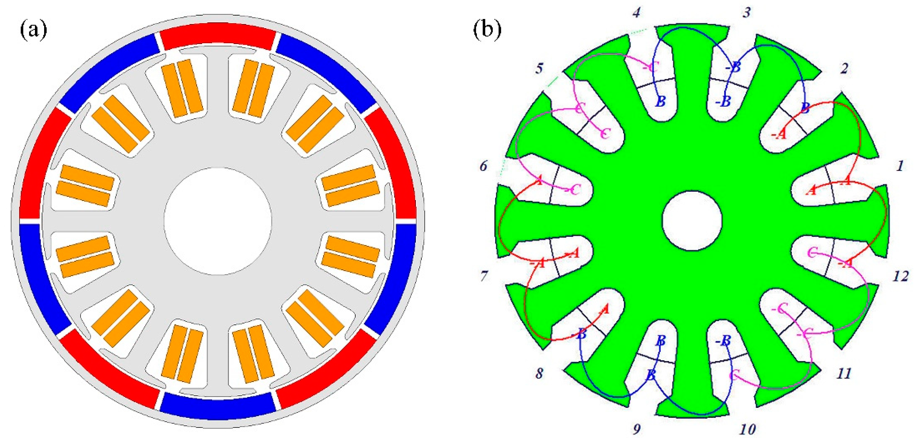
29]. In addition, the design adopts a fractional slot winding configuration. In general, the following combination was determined: the number of slots Z = 12 and the number of pole pairs p = 5. Moreover, two-layer concentrated windings were implemented to further shorten the end windings of the motor and reduce motor losses [
30]. Using ANSYS Maxwell, the simulation model for the design of the PMBLDC motor was established based on the above design considerations.
Figure 1 depicts the structure and winding configuration of the motor, while
Table 1 depicts the other design parameters.
2.2. Electromagnetic Field Finite Element Simulation
2.2.1. Characteristic Simulation in the No-Load Condition
Based on the above motor structure and parameters, no-load simulations of the motor were carried out on the ANSYS Maxwell platform to verify the validity of the design.
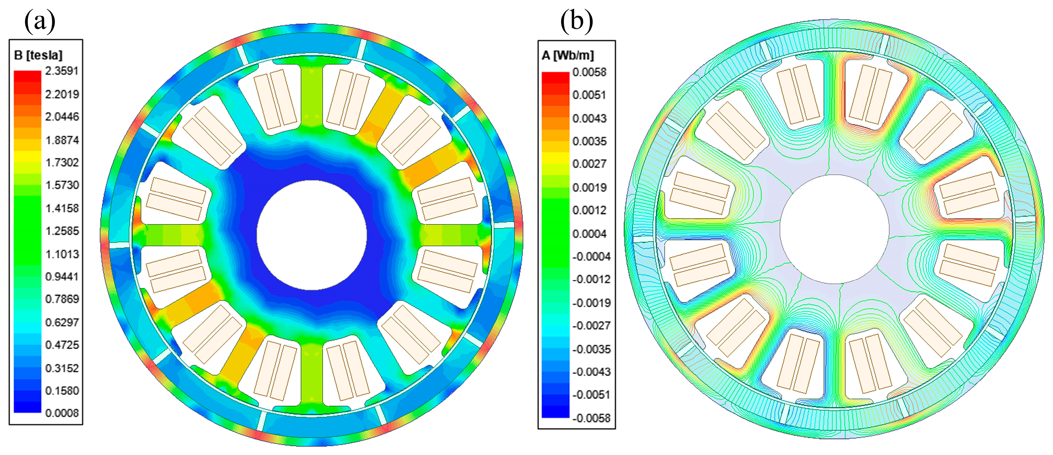
Figure 2a,b depicts the magnetic flux density and magnetic lines of force of the motor when it is rotating at an angle of 55° under no-load conditions. Observations reveal that only the stator tooth tip is saturated, and the saturated area is periodically symmetric, which has little impact on the operation of the motor. Moreover, the magnetic density of the stator yoke is not saturated and is not susceptible to demagnetization. Furthermore, the magnetic lines of force are symmetrically distributed, allowing the majority of them to enter the stator without obstruction. In other words, there is almost no magnetic flux leakage, and the distribution of magnetic lines of force is relatively optimal. Thus, it can be concluded that the magnetic flux density and magnetic lines of force of the stator in the no-load condition satisfy the design requirements.
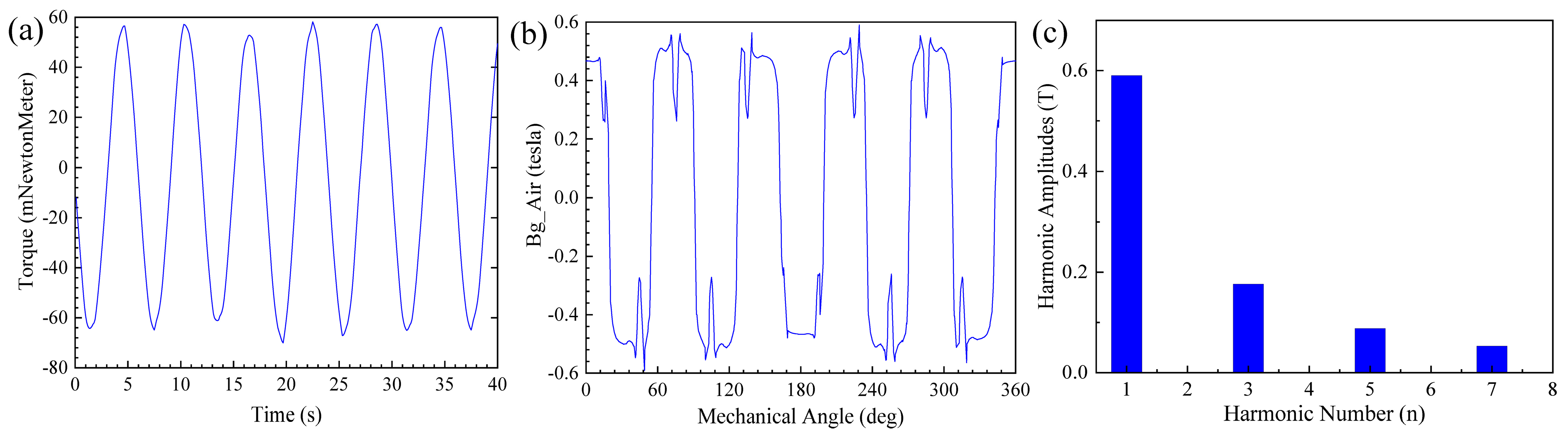
Likewise, the motor was simulated to characterize its cogging torque and radial air-gap flux density under the condition that its external excitation is unloaded; the time step of the simulation was 0.1 s. As depicted in
Figure 3a,b, the cogging torque is low, and its relatively ideal waveform is conducive to the smooth operation of the motor and reductions in vibration and noise. On the other hand, the air gap flux density waveform is approximately trapezoidal, which indicates a high efficiency irrespective of the fact that the large fluctuations at the peak and in the numerous harmonic components may reduce the ability of the motor to regulate vibration and noise. Meanwhile, a FFT spectral analysis of the radial air gap flux density (
Figure 3c) reveals that among the amplitudes of the fundamental wave, the third harmonic, the fifth harmonic, and the seventh harmonic are 0.5903 T, 0.1762 T, 0.0881 T, and 0.0528 T, respectively, with these three harmonics being the primary contributors to the air gap flux density distortion. Since an increase in harmonic components will increase torque ripple, the motor can be optimized further by decreasing the harmonic content of the air gap flux density.
2.2.2. Characteristic Simulation in the Loaded Condition
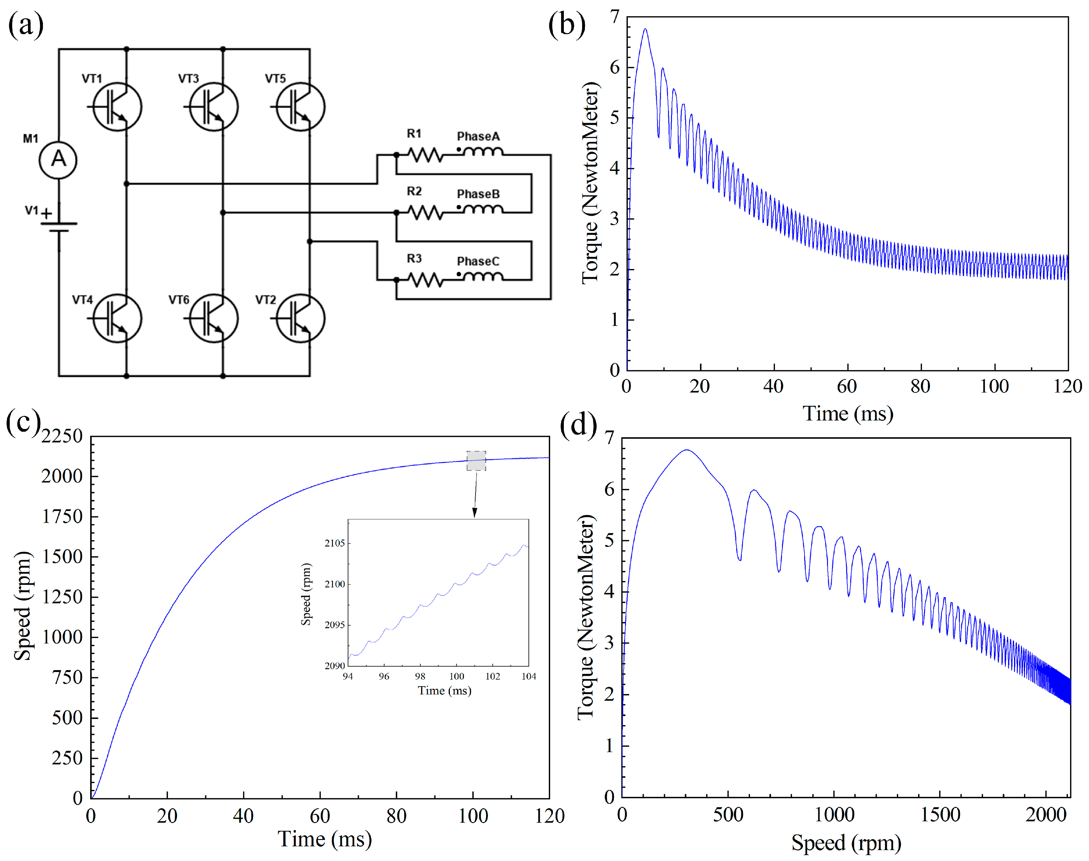
Following the no-load simulation, the motor was simulated again to characterize its performance under load. The objective was to determine if the design is capable of achieving the expected working performance at a rated supply voltage of 12 V. The control circuit diagram is shown in
Figure 4a; the time step of the simulation is 0.0002 s. First, the start-up process of the motor was simulated with a constant output power of 415 W when the mechanical characteristics are considered.
Figure 4b depicts the electromagnetic torque waveform of the process from the start-up state to the steady working state of the motor. A constant value of the electromagnetic torque is observed at approximately 2.14 N·m, suggesting that the output torque can satisfy the actual work requirements.
Figure 4c illustrates the revolution speed of the motor during its start-up and steady operation states. The speed rises rapidly at first and stabilizes at around 2200 rpm when reaching the steady state, which also satisfies the requirements.
Figure 4d shows the torque-speed curve of the motor during start-up.
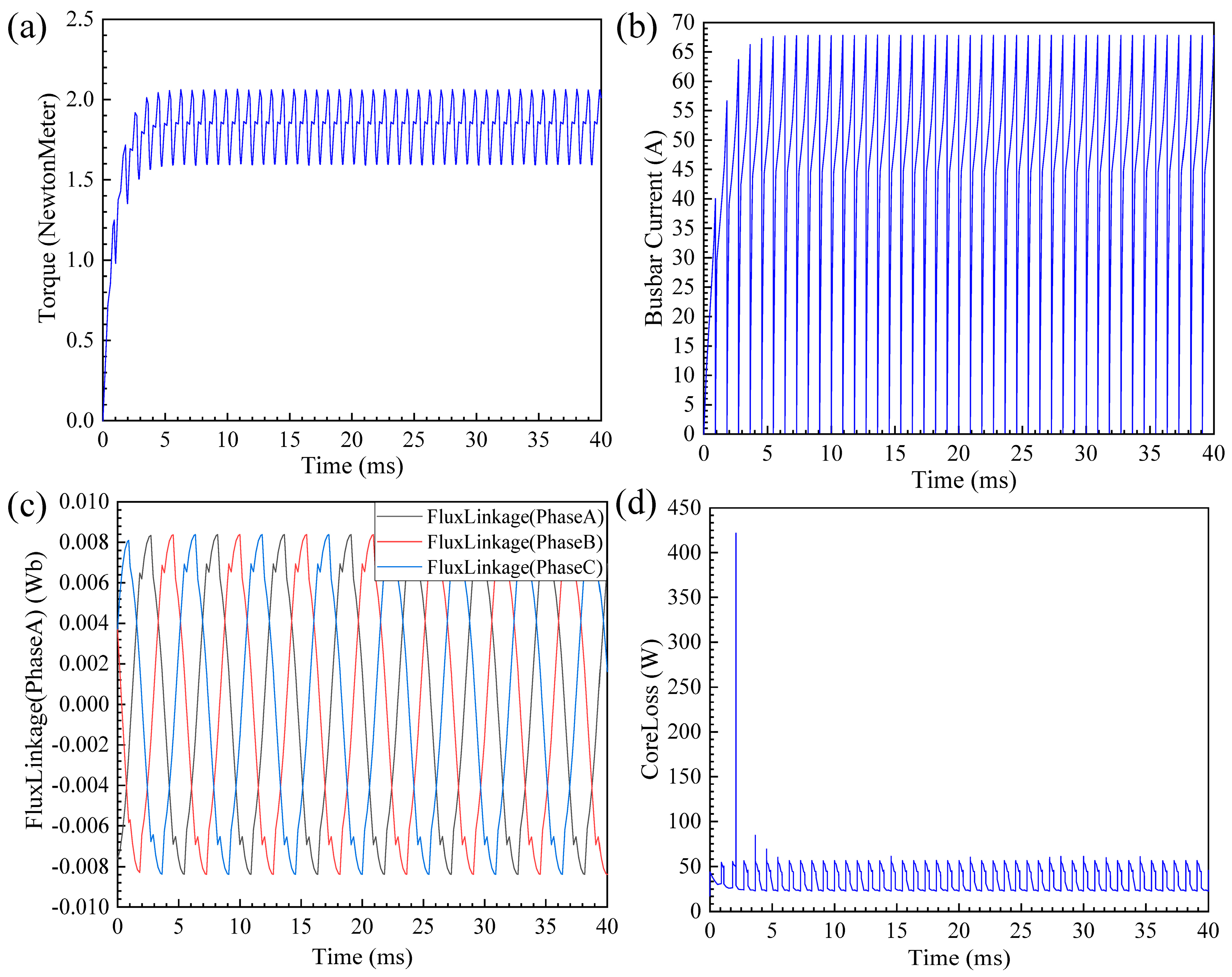
Figure 5a,b represents the waveforms of the electromagnetic torque and line current of the motor at 2200 rpm, excluding the mechanical characteristics of the motor. The time step of the simulation is 0.0002 s. The operation of the motor was unstable during the start-up phase. After a period of time, the torque gradually increased from 0 to a constant value. The average torque during the process is approximately 1.80 N·m. The RMS values of the line current is 49.13 A, indicating that the electromagnetic torque in the steady working phase can satisfy the requirements for driving a cooling fan. The simulation data of 1.8 N·m represent the maximum torque that the motor can deliver under these simulation conditions, i.e., the limit of the motor’s operation, and does not mean that the motor needs to run at this operation for a long time.
Figure 5c depicts the three-phase flux linkage diagram of the motor under rated conditions, which conforms roughly to a sinusoidal distribution, indicating that the electromagnetic properties are stable and the harmonic content is low.
Figure 5d shows the iron loss of the motor running in the rated state; the average iron loss is stable at about 33 W, meeting the requirements.
3. Load Capacity Simulation
A new simulation test was conducted to further confirm the load capacity of the motor. To observe the changes in input current, the external load of the motor was gradually increased at its rated speed (2200 rpm). Since it is difficult to change the external load at a fixed speed in ANSYS Maxwell, a method of reverse verification was adopted: the maximum torque was determined by analyzing the output torque as it varies in response to a change in input current.
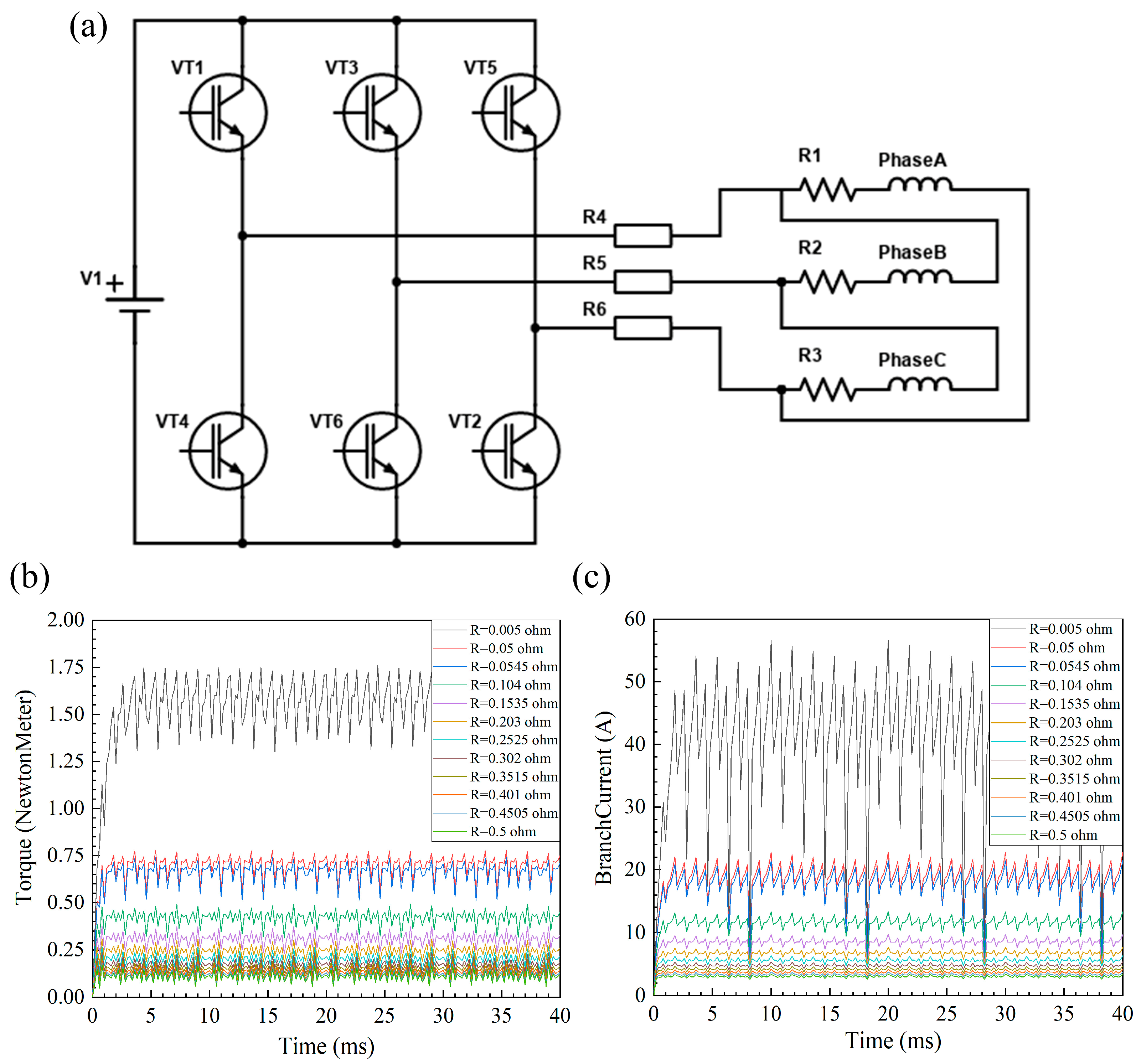
Given that the research object is a BLDC motor, the only strategy to add excitation in ANSYS Maxwell is applying an external circuit. In order to alter the input current, various resistances were added to the external circuit resistance throughout this simulation. Among the various schemes for adding the resistance, positions before the motor windings and after the three-phase inverter circuit were designated. A current meter was also included to measure the input current. The complete control circuit diagram is shown in
Figure 6a.
After the control circuit is added to the brushless DC motor, the resistance value of the resistance R4 R5 R6 was set to the same parameter, and this parameter was scanned after setting the initial value, final value, and step size. The time step of the simulation was 0.0002 s. Since the power supply voltage remains unchanged, each resistance value corresponds to a current value. This method can be used to simulate multiple different input current values when the motor is running at the rated speed. As depicted in
Figure 6b,c, the output electromagnetic torque and output line current vary with resistance. In conjunction with the simulation results obtained when the resistor was disconnected from the control circuit, the maximum electromagnetic torque of the proposed PMBLDC motor can be calculated as 1.80 N·m at an input line current of 49.13 A. This method provides a reference for other applications requiring a change in output torque at a constant speed; by varying the resistance of the control circuit to regulate the input current under a fixed supply voltage, the output electromagnetic torque of the motor can be controlled indirectly.
4. Prototype Manufacturing and Bench Test
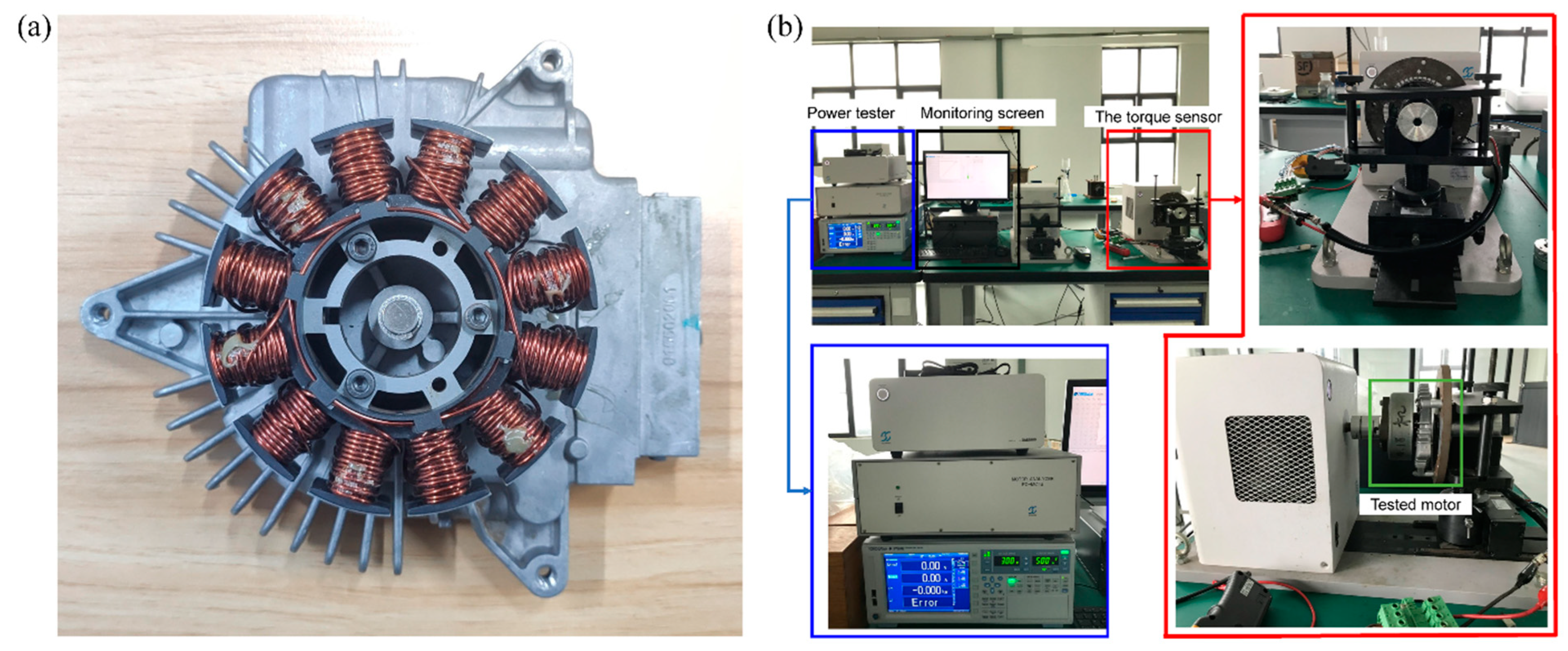
In order to further explore the actual output characteristics of the proposed PMBLDC motor, a prototype was developed and a bench test was performed. The prototype is shown in
Figure 7a. The test platform consists of a power tester, tooling, a torque sensor, and a monitoring screen. The motor prototype was connected to the torque sensor through the tooling, and a power tester was used to measure the motor power and current during the entire test process. All test data were displayed on the monitor screen in real time, as shown in
Figure 7b. The torque sensor, power tester, and the software we used are all from SUGAWARA company, using non-inductive FOC to control them. During the experiment, the motor was kept running at a speed of 2200 rpm and the external load of the motor was gradually increased to investigate the changes in the current and output power of the motor from normal operation to hindered operation.
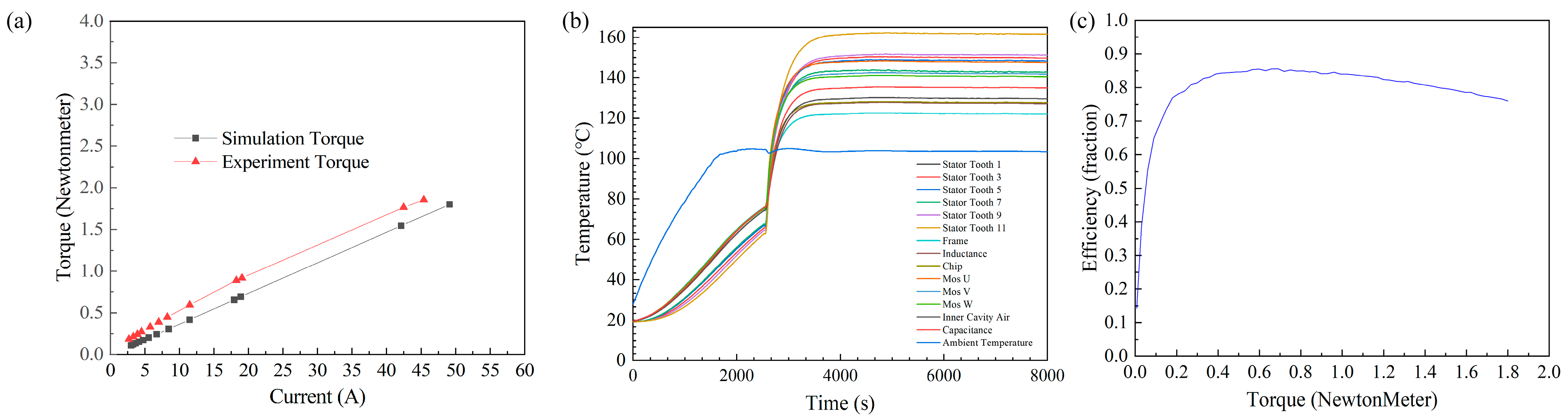
Figure 8a shows the corresponding input current-torque curve of the prototype. Taking the two points in the graph with the highest current as an example, the output torque is 1.8001 N·m when the experimental input current is 45.394 A, and 1.7996 N·m when the simulated current is 49.1331 A. The difference in torque is 0.0005 N·m when there is a difference in current torque of 7%. When the experimental input current is 42.1151 A, the output torque is 1.5443 N·m, and when the simulated current is 42.476 A, the output torque is 1.7098 N·m. When the current difference is 0.36 A, the torque difference is 10%, and the error is within the acceptable range. The reason for this error between experimental data and simulation data is mainly due to the fact that the motor adopts the external circuit as the excitation source when simulations are carried out, so that there is a certain gap between the resistance value of the armature winding in the simulation and that in the experiment, and the winding part in the external circuit cannot be fully equivalent to the motor winding. This leads to a certain difference between the experimental data and the simulation data. However, the experimental results verify the conclusion drawn from the simulation that the design of the motor can meet the requirements and can output a maximum torque of 1.8 N·m at 2200 rpm. At the same time, a temperature change diagram of each part of the motor was output by the temperature sensor, as shown in
Figure 8b. The temperature of the motor gradually increases at the beginning of the experiment, and then tends to be stable. The temperature figure is based on the measured temperature of the motor under extreme operating conditions; the motor is not required to operate at this temperature for a long period of time and the motor can withstand this temperature due to its class F insulation material. Therefore, we consider that this temperature is acceptable.
Figure 8c shows the efficiency of the motor based on the experiment data. From this image, it can be seen that the efficiency of the motor can reach 0.85; this efficiency is within the acceptable range due to the low cost of the motor. Therefore, the rationality of the simulation of the design through ANSYS Maxwell has been further corroborated.


