Article

Round-Trip Wireless Charging Infrastructure for Heterogeneous Electric Vehicles on Highways: Modelling and Optimization

1
Laboratory of Modeling and Mathematical Structures, Faculty of Science and Technology of Fez, Fez 2202, Morocco
2
Digital Engineering and Artificial Intelligence School, EuroMed University of Fes, Fez 2202, Morocco
*
Author to whom correspondence should be addressed.
World Electr. Veh. J. 2023, 14(6), 160; https://doi.org/10.3390/wevj14060160
Submission received: 14 May 2023 / Revised: 1 June 2023 / Accepted: 10 June 2023 / Published: 15 June 2023

Abstract

:
In this paper, we propose a new approach to dynamic wireless charging that allows electric vehicles to charge wirelessly while in motion in both lanes on highways. The challenge is to locate the charging infrastructure on a highway between origin O and destination S (round trip) with heterogeneous battery vehicles, where each type of vehicle requires its allocation of charging segments on the road. We aim to ensure that each type of vehicle can complete a round trip without running out of battery charge while minimizing the number of charging segments and inverters on the road by studying both lanes simultaneously. We model the problem mathematically and validate it using a CPLEX optimizer for limited instances. Finally, we solve the problem using a hybrid approach that combines genetic algorithms and local search techniques to balance diversification and intensification. We have significantly improved the results found in the literature by reducing the number of inverters, which are expensive components in the charging infrastructure. Our approach takes advantage of utilizing a single inverter for both lanes of the highway, leading to cost savings and improved efficiency.

1. Introduction

Electric vehicles are rapidly gaining importance in the automotive industry due to their potential to reduce greenhouse gas emissions and improve air quality. According to a report by the International Energy Agency (IEA) [1], electric vehicle sales in 2020 reached a record high of 3.1 million, a 41% increase compared to the previous year (IEA, Paris, France, 2021). The report also predicts that by 2030, over 145 million electric vehicles will be on the road worldwide. Electric vehicles (EVs) have gained popularity due to their zero emissions when in motion, making them an environmentally friendly option for transportation. This characteristic is one of the reasons governments incentivize the purchase of electric vehicles by offering various subsidies and incentives to individuals and businesses. Electric vehicles consist of three essential components. Firstly, the battery system serves as the primary power source, storing and supplying electricity to propel the vehicle. Secondly, the electric motor converts electrical energy into mechanical motion, driving the wheels. Finally, the electric drive unit controls the power distribution and manages the overall performance of the vehicle’s propulsion system. Together, these components enable the efficient and eco-friendly operation of electric vehicles.
By allowing an EV to receive energy wirelessly during its motion, the range anxiety of EV drivers can be significantly reduced, particularly in cities with large travelling distances between the different locations [2].
As electric vehicles become increasingly popular, it is essential to consider how they will be charged. Traditional charging methods require the vehicle to be plugged into a power source, which can be inconvenient for drivers who need to find a charging station and wait for their car to charge. This is where wireless charging via induction can provide a solution by using magnetic fields to transfer conveniently and efficiently. This technology could also increase the adoption of electric vehicles by reducing range anxiety and making charging more accessible. As electric vehicles continue to gain traction, it is clear that wireless charging via induction will play an essential role in the future of sustainable transportation.
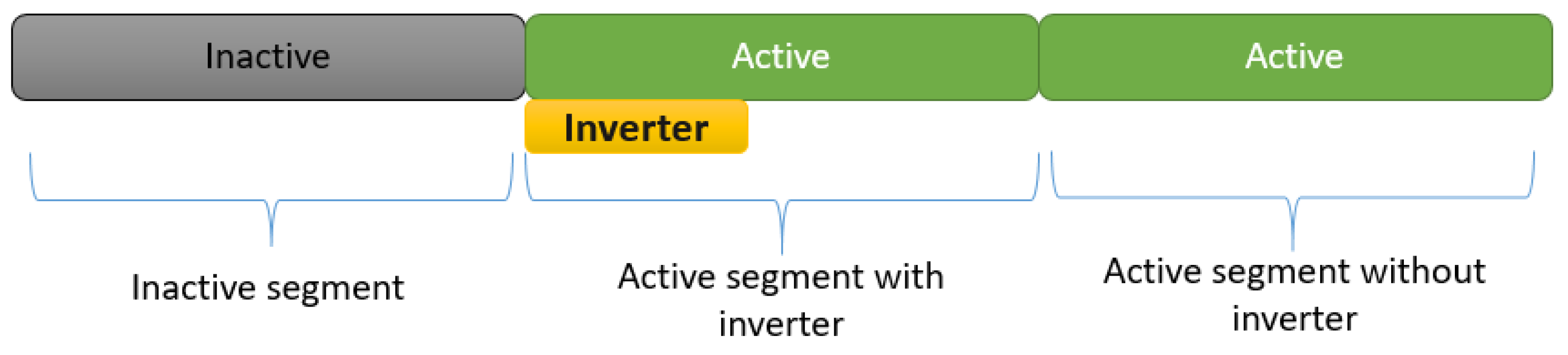
While wireless charging via induction is a promising technology for electric vehicles, it is essential to consider the cost implications. Installing wireless charging infrastructure for electric vehicles is currently more expensive compared to traditional charging methods. This cost disparity necessitates careful planning and significant investment for achieving widespread adoption. A wireless charging pad consists of an inverter and a series of segments designed for charging. The energy between two coils and wireless charging eliminates the need for cables and plugs.
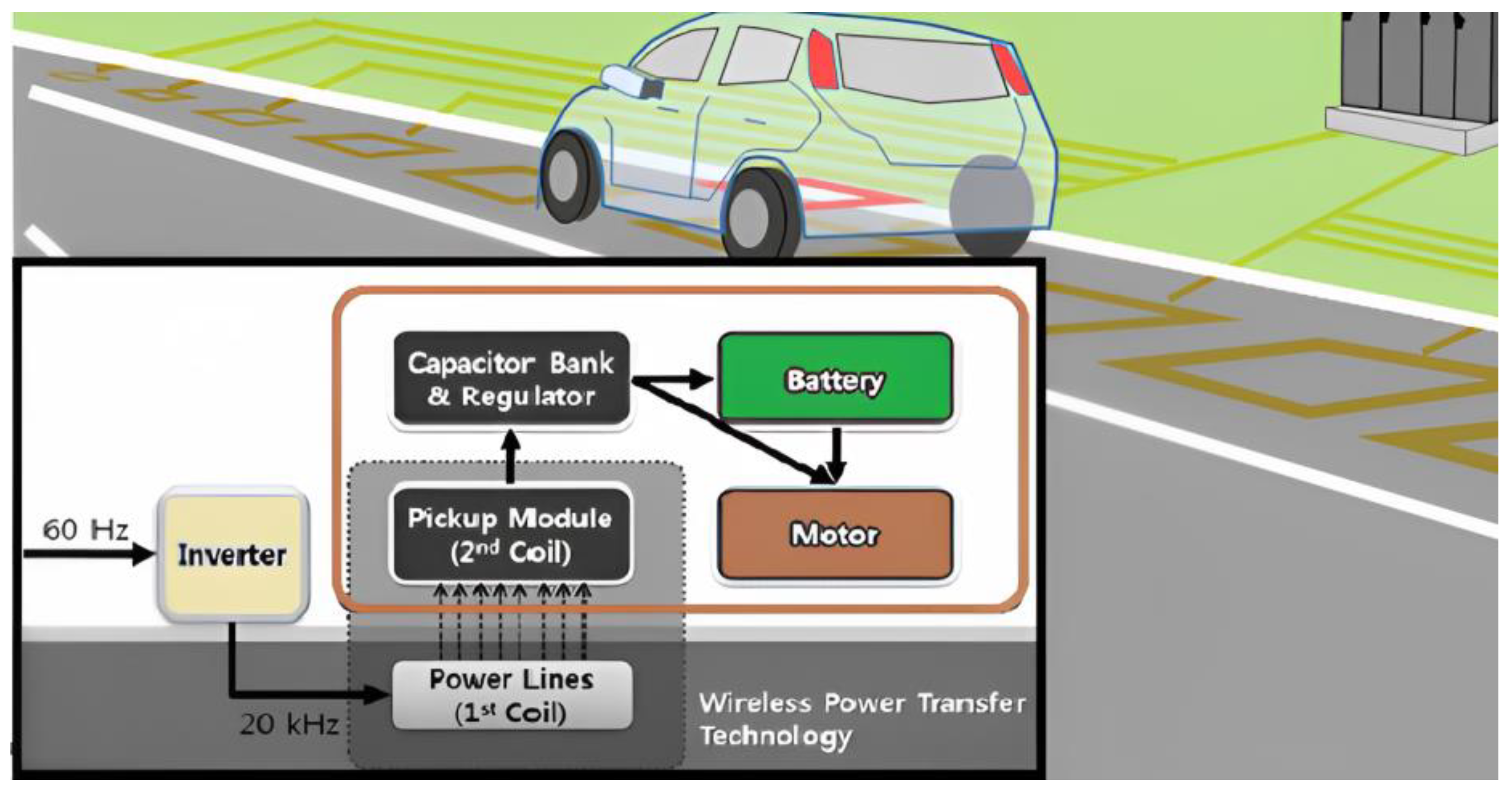
A wireless charging system typically includes a power factor correction (PFC), inverter, primary topology, transmitting coil, receiving coil, secondary topology, rectifier, and load [3]. The inverter converts AC power from the grid into the high-frequency AC power needed for the wireless charging process. The segments, made up of wire coils, generate a magnetic field when current is passed through them. This magnetic field induces a current in the receiving coil on the underside of the electric vehicle, which is then converted back into DC power to charge the battery. The charging pad regulates the amount of power transferred to the vehicle, ensuring the charging process is safe and efficient. By using this wireless charging method, electric vehicle owners can enjoy the convenience of charging without having to plug in their vehicle, making the process more efficient and user-friendly. A representative diagram is shown in Figure 1.
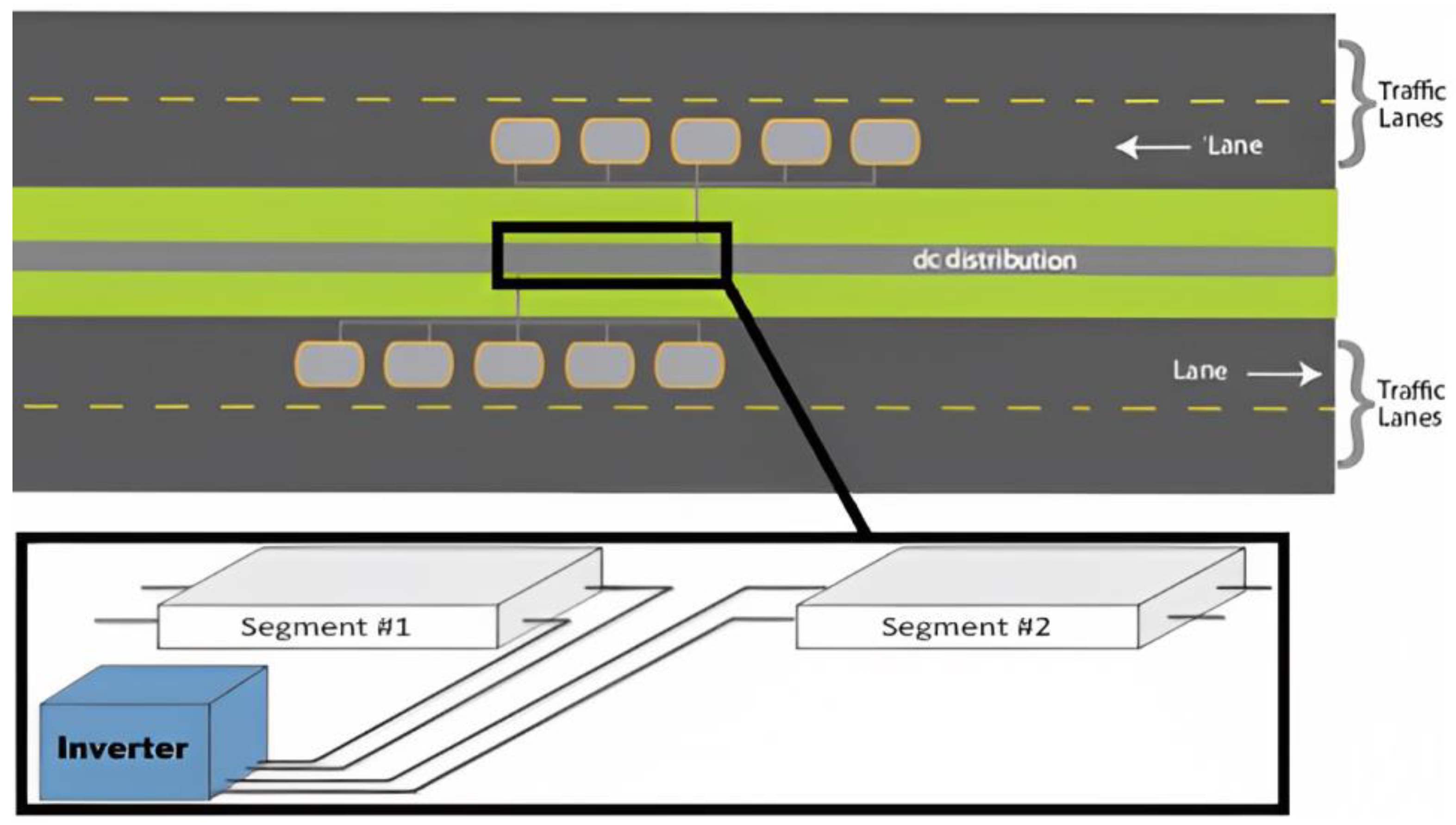
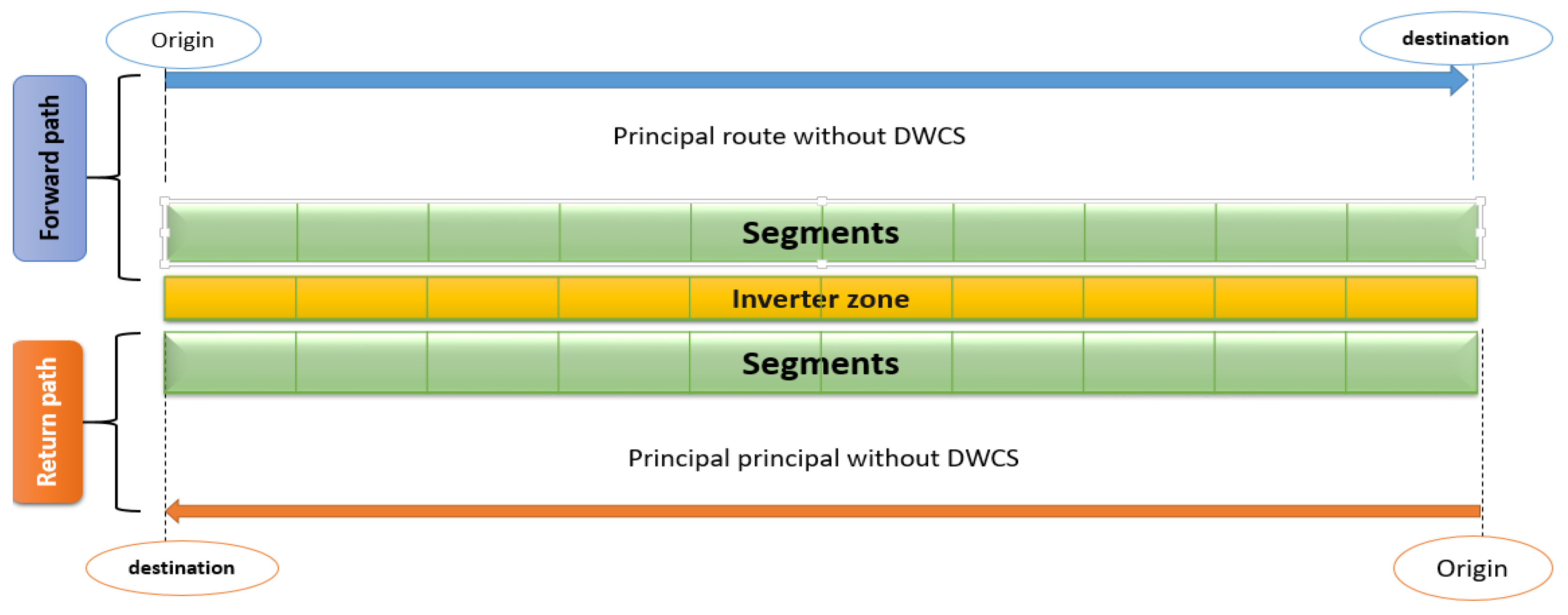
Wireless charging solves the problem of journeys with long distances like the highway. It is characterized by a long distance between the origin and the destination. The high speed of vehicles on this kind of road drains their battery very quickly, which requires very good planning to minimize the cost of the infrastructure installed on the highways. In particular, highways with unseparated lanes could benefit from wireless charging technology, as it allows for the simultaneous charging of electric vehicles in both lanes. This approach could also reduce the overall cost of the infrastructure, as the same inverter could be used for both lanes. This type of installation would require careful planning and coordination, as well as investment in the necessary infrastructure. However, the potential benefits of this approach could be significant, as it would provide a convenient and efficient charging option for electric vehicle drivers on highways. Furthermore, as the demand for electric vehicles continues to grow, installing wireless charging infrastructure on highways could accelerate the transition to a more sustainable transportation system. Figure 2 shows the use of the same inverter for both highway lanes to minimize the infrastructure cost.
Among the main challenges of electric vehicles are charging methods and those related to the battery. In their article, Habib et al. [4] provide an overview of various charging techniques for electric vehicles and examine their effects on power distribution systems. They also investigate coordinated and non-coordinated charging methods, delayed loading, and intelligent charge planning. The study concludes by examining the financial advantages of vehicle-to-grid (V2G) technology concerning charging approaches. Shuai et al. [5] presented an overview of the contemporary economic model electric vehicles have created, considering the one-way and two-way energy flows enabled by EVs (wherein the vehicles can supply energy to the power grid). Their study scrutinized diverse EV charging infrastructures and techniques for unidirectional charging and bidirectional energy trading. They also investigated the feasibility of utilizing these vehicles as storage for renewable energy. Several researchers have also explored the various approaches proposed for charging electric vehicles. For instance, Tan et al. [6] conducted a comprehensive analysis of the benefits and challenges of vehicle-to-grid (V2G) technology in both unidirectional and bidirectional charging modes. They also highlighted the obstacles associated with V2G implementation, such as battery degradation and high capital costs.
Additionally, they compiled a list of V2G optimization strategies that are classified based on the method used (e.g., Particle Swarm Optimization (PSO) and genetic algorithms (GAs)). Similarly, Hu et al. [7] provided an overview and categorization of intelligent charging techniques for electric vehicle fleets, focusing on fleet operators. They discussed topics such as battery modelling, charging and communication standards, and driving patterns. Furthermore, they presented several control strategies for managing EV fleets, as well as mathematical algorithms for modelling them. In another study, Rahman et al. [8] outlined various approaches utilized for addressing problems related to charging infrastructure for plug-in hybrid electric vehicles (PHEVs) and battery electric vehicles (BEVs).
Another significant aspect of electric vehicle (EV) charging pertains to battery management and battery health and longevity estimates, as these are crucial factors in enhancing battery lifespan. Li et al. [9] provided an overview of recent developments in Big Data analytics that facilitate data-driven battery health assessment. They categorized the approaches based on their feasibility and cost-effectiveness and evaluated their advantages and limitations. Meanwhile, Liu et al. [10] introduced a machine learning-based system that employs Gaussian process regression (GPR) to predict lithium-ion batteries’ ageing. In contrast, some studies have focused on advanced fault diagnosis techniques, since battery defects can lead to a decline in performance (Hu et al. [11]).
Most of the travel on urban roads happens over short distances, which does not provide a significant challenge to the adoption of EVs. For most short-distance commutes, there is likely to be an opportunity to recharge at the destination without the need for dynamic charging. With most of the long-distance travel happening on highways, dynamic wireless charging infrastructure on highways can play a significant role in reducing range anxiety. High-power dynamic wireless charging systems will be necessary for roadway electrification to provide sufficient energy to EVs. In this context, we find the work of Wang et al. [12], who presented a dynamic reversal approach for wireless charging lanes when automated and connected vehicles are present on a highway. This method seeks to enhance highway traffic flow and accommodate electric vehicles’ varying charging requirements in different directions. The authors created a mixed linear program to implement the proposed path reversal strategy and proved its effectiveness through numerical experiments. In their research, Bourzik et al. [13,14] suggested the installation of entry gates to Dynamic Wireless Charging (DWC) for EVs requiring a battery recharge and exit gates leading back to the main road for those who do not. Their study had two goals: first, to reduce the DWC usage cost for each vehicle type during the highway trip, and second, to identify the most cost-effective location for installing the gates on the road. The authors formulated the problem as a mathematical model and applied the non-dominated sorting genetic algorithm (NSGA-II) to obtain a solution.
Fuller [15] introduced a flow-based model that aims to reduce the capital expenditure of implementing dynamic recharging infrastructure along California highways to accommodate the charging demands of EVs travelling between critical origins and destinations in the state. This model also considers the possibility of drivers reducing their EV’s speed while in the charging lanes to maximize energy replenishment. Xiaotong Sun et al. [16] studied the most effective strategy for deploying static and dynamic charging infrastructure while taking into account the interdependence of transportation and power networks.
Ahmad et al. [17] proposed a novel approach to reduce electric vehicle charging time by utilizing heterogeneous Battery Switching technology as an alternative charging option. They proposed a scheduling technique to minimize wait time and power loss at the designated Battery Switching Station. Zhang et al. [18] introduced battery heterogeneity in the context of Battery Swapping (BS) services, where different types of electric vehicles (EVs) coexist, proposing a BS service framework based on battery heterogeneity.
Elbaz et al. [19] presented a mathematical model that takes into account various factors affecting EV charging demand, including the number of EVs, alternative charging options, and the distance between charging stations. They also considered how different charging methods, such as dynamic and static charging, affect battery life.
In 2022, Elbaz et al. [20] put forth a model to find the best spots to install wireless charging stations for EVs and determine the number of charging points at each location for the Round-Trip scenario. Meanwhile, Bourzik et al. [21] investigated the issue of optimal locations for wireless charging infrastructure for heterogeneous battery EVs on highways with a single path. They used a road divided into equal-length segments to determine where to place the charging stations.
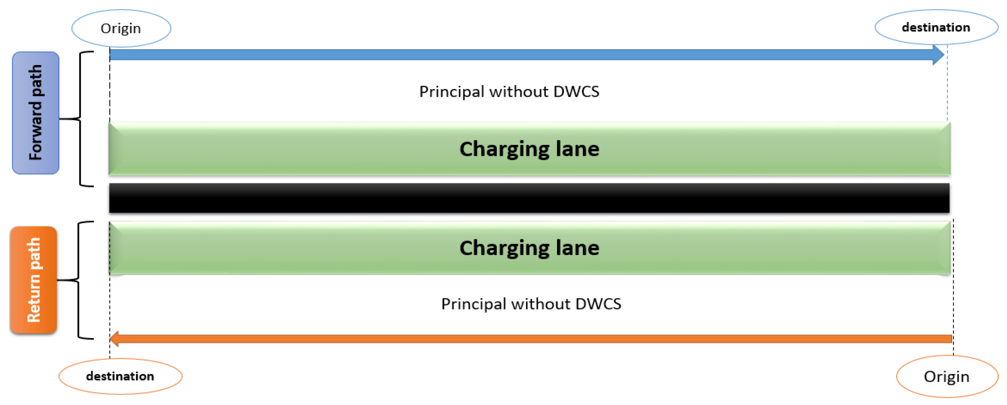
Most studies have concentrated on static or dynamic wireless charging infrastructure allocation, aiming to optimize its cost. However, this research focuses on a scenario where the electric vehicles are identical and treat the problem on the road with a single lane. Our contribution to this work is to propose a mathematical model for the study of the planning of electric vehicle infrastructure on highways by considering the two highway lanes simultaneously (for a round trip) with heterogeneous batteries. Then, one can solve the proposed mathematical model using a hybrid approach that combines genetic algorithms and local search techniques to balance diversification and intensification.
Initially, we explain the wireless charging technology. Subsequently, we propose an integer programming method to achieve an optimal infrastructure after describing the problem. The CPLEX optimizer is used to validate our model. Then, we apply an approximate method based on genetic algorithms and a local search on a real case study in the literature to compare with the case of studying each path separately. We analyze and discuss the results to highlight the effectiveness of our model, emphasizing the importance of studying the round trip and using the same inverters for both lanes to reduce infrastructure costs. Finally, we conclude by discussing the optimal placement of wireless charging infrastructures in transport networks. Electric vehicles have become the subject of much research today as they are considered the future of green logistics. This technology eliminates the need for various fuel types, and numerous studies have been conducted in this area.

2. Problem and Mathematical Modelling

2.1. Problem Descriptions and Objectives

Our goal in this work is to find an optimal location for the wireless charging infrastructure on a long highway road in the Round-Trip Case to ensure the trip of a set of heterogeneous vehicle batteries going from the origin to the destination of each path. We consider a highway with two paths, the first for the forward and the second for the return path, and a set of vehicles with heterogeneous batteries. We seek to satisfy the needs of the load at the least cost during their journeys from origin to the destination by allocating the power transmitters on both paths, like dynamic stations (Figure 3).
We assume that each path of the highway is divided into two zones, the 1st, a principal road without DWCS, and the 2nd, a zone where we will put the DWCS, called the charging lane (Figure 4).
The 2nd zone of each path is subdivided into segments with the same length, and we will consider each segment as a potential transmitter. If the charging is needed, the segment will be equipped with an inductive emitting cable plus an inverter or will fit only with an emitting cable, and if the loading is not needed, the segment will be inactive [19] (see Figure 5).
We note that a single inverter can power a limited series of successive active segments, so if the inverter capacity is exceeded, in this case, we need another inverter to power up the other active segments. In addition, the same inverter can power the active segments of both paths. Figure 6 shows the highway with segments and inverters. If a vehicle needs the load, it will use the segments zone. If not, it will use the principal route.
Each type of battery requires its allocation of segments because of the heterogeneity of batteries; for that, we search to determine the minimum of active segments in each path and inverters to meet the energy needs of each vehicle type.

2.2. Mathematical Model

We seek to model the problem as a mathematical problem with constraints. We present as follows a set of notations, data, constraints, and objective functions. In this work, we assume that the wireless charging system can supply each type of vehicle.

2.2.1. Notations and Data

Assuming that the batteries in vehicles are diverse, let V be the collection of all vehicle batteries, and let k be an index representing a particular vehicle type with k     0 , , V .
The infrastructure cost includes both the recharge segment expenses and the cost of inverters. The cost of a single active segment without an inverter is denoted as C s g t , while the unit cost per inverter is represented as C i n v .
As previously noted, the highway with two paths is indexed by p , where p   ϵ   0 , 1 . We discretized the second zone of every highway path into equally sized segments. The initial and final segments are referred to as O and f , respectively, while the intermediate segments are labeled as g , where g     O , , f .
We consider one vehicle of each type making the trip from O to S of each path p , and we note that t O p represents the arrival time of the fleet of vehicles at the entry point of the segment O of the path p (the starting point of the highway path). As mentioned earlier, each vehicle type has its characteristics, so they do not have the same speed and acceleration on the highway, such that each vehicle type k has its arrival time at the entry point of each g th segment of each path p , which we note by t g p ,   k . We assume that we know the arrival time t g p ,   k .
The rate of battery power consumption is denoted by D k t and is dependent on various factors such as the energy consumption rate of the vehicle, which is determined by the speed of the path, the slope of the road, and the use of peripherals such as the car air conditioner. On the other hand, S k t represents the battery power supply at time t . This quantity is determined by the charging transmitter’s allocation of power and the magnetic flux generated, which can vary as a function of time.
We consider the following notations:
  • E b a t k : The battery capacity of vehicle k
  • E l o w k   and   E u p k : The lower and upper limits of the battery level, respectively. These values have the following relationship: E l o w k = E b a t k × δ and E u p k = E b a t k × β with δ ,   β   0 , 1
  • N i n v : The maximum number of the active segment in each series that can use one inverter.

2.2.2. Decision variables

The second zone of each highway path is subdivided into several congruent segments, and we search the minimum number of active segments and inverters into the road; we define two decision variables X g p   and   Z g p such as
X g p = 1       if   the   g t h   segment   of   the   path   p   is   active 0 otherwise
If X g p = 1 , in this case, the segment g of the path p will be active and the vehicles can enter to the second zone to use the segment g . If X g p = 0 , In this case, the segment g is inactive, and any vehicle cannot use the segment g and there are no doorways to enter this segment.
Z g = 1 if   the   g t h   segment   has   an   inverter 0 otherwise
If Z g = 1 , the active segment g needs an inverter, OR else the segment g will be without an inverter.
Each type of vehicle has its character because of the heterogeneity of the batteries, so the use of the segments is different from one kind of vehicle to another, so an active segment may be used by some vehicle and not for others; we then define the decision variable y g p ,   k such as:
y g p ,   k = 1 if   the   vehicle   k   decides   to   charge   the   energy   via   the   segment   g     of   the   path   p 0 otherwise
If y g p ,   k = 1 , the vehicle k will charge the energy via the segment g of the path p , and in this case, the vehicle k enters the zone 2 of the path p to use the segment g . If y g p ,   k = 0 , the vehicle k does not use to the segment g of the path p to charge, and in this case, the vehicle continues the trip on zone 1 of the road.
Let E k t be the amount of energy in the battery k at time t ; this quantity is described as:
d E k t   d t = S k   t if   the   vehicle   k   is   in   charging   mode   on   the   zone   2 D k   t if   the   vehicle   k   is   in   the   zone   1

2.2.3. Constraints

The problem is modeled under a set of constraints described below:
E k t O p = E u p k k = 0 , , V ,   p   ϵ   0 , 1
We assume that vehicles start at the beginning of each highway path with the maximum load, such that the amount of energy in each battery k at time t O p is equal E u p k .
E k t g p , k + t g p , k t g + 1 p , k ( D k t 1 y g p ,   k + S k t × y g p ,   k ) ) d t E l o w k
k = 0 , , V ;   g = 0 , ,     f 1 ;   p   ϵ   0 , 1
The initial component of Equation 2 signifies the energy level of vehicle k when it reaches segment g . The second term denotes the amount of energy consumed by vehicle k from the start of segment g to the beginning of segment g + 1 , provided that the vehicle has not utilized segment g ( y g p ,   k = 0 ). However, if the vehicle has made use of segment g ( y g p ,   k = 1 ), the second term is nullified since the battery is being recharged during the segment g , and the third term signifies the amount of energy replenished by the vehicle during that time. Therefore, constraint (2) mandates that the remaining charge at the commencement of each segment g + 1 always exceeds the lower limit of the battery’s charge. In simpler terms, vehicles must utilize the segments in a manner that ensures the energy level remains above the minimum threshold.
E k t g + 1 p , k = min {   E u p k   ;   E k t g p , k + t g p , k t g + 1 p , k ( D k t 1 y g p ,   k + S k t × y g p ,   k ) ) d t }
k = 0 , , V ;   g = 0 ,   ,   f 1 ;   p   ϵ   0 , 1
Constraint (3) updates the remaining charge at the beginning of each segment g + 1 . The battery energy level of each vehicle k should be less than the upper limit of the battery   E u p k . If the energy amount is more than the upper limit, then the energy level would be   E u p k .
y g p ,   k   X g p       k = 0 , , V ;       g = 0 , ,   f   ;   p   ϵ   0 , 1
Constraint (4) enforces the activation of segment g on path p if any vehicle type chooses to recharge using that segment. This constraint ensures that all necessary segments for charging are operational and available to the vehicles that require them.
X g p k ϵ V y g p ,   k           g = 0 ,   ,   f ;   p   ϵ   0 , 1
Constraint (5) mandates that if no vehicle type chooses to recharge using segment g on path p , then the segment must be inactive.
X g 0 + X f 1 1 Z g ;       g = 0 , ,     f
Constraint (6) guarantees that if an inverter is present in segment g , at least one of the two paths must have an active segment in g . This ensures that the inverter can function as intended and prevents energy loss or other potential issues that may arise from an inoperative inverter.
X g 0 + X g 1 0 Z g   ;     g = 1 , ,   f
X f g 1 + X f g + 1 1 Z g   ;       g = 1 , ,   f
Constraints (7) and (8) have been implemented to ensure that there is at least one inverter at the beginning of each series of active segments in both directions. This requirement guarantees the proper functioning of the system and its ability to transmit energy effectively.
Z g   1 X g 1 0 ;       g = 1 , ,   f
Z f g   1 X f g + 1 1 ;       g = 1 , ,   f
Constraints (9) and (10) have been imposed to ensure that there is a maximum of one inverter in any given series of active segments in both lanes.
Z g i = 0 N i n v 1 X g 1 0 r = 0 i X g + r 0 + r = 0 i 1 X f g + 1 1 r = 0 i X f g + 1 1 N i n v ;   g = 1 , ,   f
Constraints (11) mandate that the cable length of each inverter must not exceed N i n v , which is the maximum permissible length for a single inverter.

2.2.4. Objective Function

Our objective is to optimize the infrastructure cost by minimizing the number of active segments and inverters used in two paths. To achieve this, we have formulated an Equation (12) that calculates the cost of the infrastructure based on the number of active segments and inverters used. The first term in (12) represents the cost of active segments in both paths of the highway, which is calculated by multiplying the number of active segments with the unit cost of each segment. The second term calculates the cost of inverters used in the road, which is calculated by multiplying the number of inverters with the unit cost of each inverter. By minimizing the number of active segments and inverters used in the road, we can significantly reduce the infrastructure cost while still ensuring the proper functioning and reliability of the system.
M i n   C s g t × p = 0 1 g = 0 f X g p + C i n v × g = 0 f Z g

3. Problem Solving

3.1. Problem Validation

The CPLEX Optimizer is a powerful mathematical optimization software package developed by IBM. It offers a suite of solvers for solving various mathematical programming problems. One of the critical roles of the CPLEX optimizer is to validate mathematical models by checking the accuracy and functionality of the constraints used in the model. It can ensure that the model is solving the problem as intended and can alert users to any errors or inconsistencies in the formulation. The following constraints have been modified in order to validate the mathematical model using CPLEX:
The third constraint is substituted with the subsequent constraints.
E k t g p , k + t g p , k t g + 1 p , k ( D k t 1 y g p ,   k + S k t × y g p ,   k ) ) d t E u p k   E k t g + 1 p , k = E u p α
E k t g p , k + t g p , k t g + 1 p , k ( D k t 1 y g p ,   k + S k t × y g p ,   k ) ) d t < E u p   α   E k t g + 1 p , k = E k t g p , k + t g p , k t g + 1 p , k ( D k t 1 y g p ,   k + S k t × y g p ,   k ) ) d t
Finally, the following constraints should be added to replace Constraint (11):
  X g = 0     Z g = 0
  X g = 0   and   X g 1 = 0     Z g = 1
  X g = 1   and   k = 1 N i n 1 X g k = N i n 1   Z g = 1
  X g = 1   and k = 1 N i n 1 X g k   N i n 2   and   X g 1 = 1 Z g = 0 = 0
All other constraints are unchanged.

3.1.1. Transport Network Data

The aim of this subsection is to validate our mathematical model by utilizing the CPLEX optimizer. To do so, we refer to an example previously studied by Bourzik et al. in [9], which involves a road consisting of a single path spanning 7500 m between the origin point O and destination point S. In their study, four types of vehicles were considered, and the objective was to transport them from O to S without running out of charge while minimizing infrastructure costs. In our case, we seek to achieve the same goal, but for both paths from O to S and back to O using the second path. Table 1 and Table 2 contain important information such as energy supply rates, energy consumption rates, and other relevant data for each type of vehicle. We take a segment of length 100 m as a reference unit.

3.1.2. Results

To determine the optimal locations for inverters and active segments, we will divide both routes into segments of equal length. It is crucial to choose the segment length wisely, as it significantly affects infrastructure costs. In our analysis, we experimented with the same segment lengths used in [21] that include 150, 200, 250, and 300 m, with the aim of minimizing infrastructure costs. The results of our investigation are presented in Table 3, which provides the total number of segments in both paths, the number of inverters, and the infrastructure cost. Table 4 provides an overview of the results achieved for each discretization; it shows the results in the case if the infrastructure is generated in each path independently of the other using the analysis presented in [21].
The results from CEPLEX (as shown in Table 3) have successfully met all the constraints determined by our mathematical model. This phenomenon can be explained by the fact that when a vehicle type utilizes an active segment, it will use the entire segment regardless of whether its battery becomes saturated midway through the segment. Thus, the more the length of the segments is suitable for the vehicle’s load needs, the better the infrastructure cost. Our results demonstrate our approach’s quality, as we identified multiple solutions based on different segment lengths. Specifically, we determined that a segment length of 250 would provide the most cost-effective infrastructure for our instance.
Table 4 presents the results obtained from [21], wherein the infrastructure is generated independently in each path without considering the other. Comparing these results with our findings (Table 3) shows that the infrastructure cost per discretization is significantly lower when both paths are analyzed to minimize infrastructure costs. This highlights the importance of considering both paths simultaneously to achieve optimal infrastructure cost reduction.

3.2. Resolution Approach

A genetic algorithm (GA) is a computational optimization method that mimics the process of natural selection to find the optimal solution for a problem. GA creates a population of candidate solutions and then repeatedly applies genetic operators such as mutation, crossover, and selection to create a new generation of candidate solutions.
While GAs can be very effective at finding reasonable solutions to complex optimization problems, they can also be slow to converge, especially when faced with many local optimization problems. One way to address this issue is to combine GAs with other optimization techniques, such as local search.
Local search is a technique for exploring the space of possible solutions by making incremental changes to a current solution in order to find a better one. Local search algorithms are often very efficient at finding good solutions near an initial solution, but they may get stuck in local optima and fail to find the global optimum.
Hybridization is the process of combining two or more optimization algorithms to take advantage of their respective strengths and overcome their weaknesses. Genetic algorithm hybridization with local search involves using a GA to explore the search space and identify promising regions and then applying local search algorithms to these regions to refine the solutions and find the global optimum.
By combining these two optimization techniques, genetic algorithm hybridization and local search can achieve better results than either method alone, especially for complex optimization problems with many local optima.

3.2.1. Principles of Genetic Algorithms

To understand the principle of genetic algorithms, let us first recall the most important mechanisms that underlie evolution [22]:
  • Evolution occurs on chromosomes that represent individuals in a population.
  • The process of natural selection ensures that the best-adapted chromosomes reproduce more often and contribute more to future populations.
  • During reproduction, the information contained in the parents’ chromosomes is combined and mixed to produce the chromosomes of their offspring (“crossing over”).
  • The result of crossing over can be modified by random disturbances (mutations).
These mechanisms can be employed to define a genetic algorithm similar to the one described below (Algorithm 1).
Algorithm 1. Genetic algorithm
  • Generate an initial population of N solutions.
  • Evaluate each individual in the population.
  • Generate new solutions by selecting parents proportionally to their evaluation scores, and apply crossover and mutation operators during reproduction.
  • Once N new individuals have been generated, they replace the old population. Evaluate the individuals in the new population.
  • If the allotted time has not been exceeded (or the maximum number of generations has not been reached), return to step 3.
To adapt a genetic algorithm to an optimization problem, it is necessary to specialize certain components to the problem’s particular structure. In general, decisions must be made regarding the following aspects:
  • Solution encoding: a correspondence must be established between the problem’s solutions and the chromosomes.
  • Genetic operators: crossover and mutation operators must be defined for the chromosomes.
  • Chromosome evaluation: the chromosomes’ adaptation to their environment is measured by a function that is calculated by a more or less complex process.

3.2.2. Local Descent

Local descent is an optimization algorithm used to find the local optimum of a function. It starts with an initial solution and iteratively improves it by moving towards the best neighboring solution until no better solution can be found in the neighborhood. The algorithm stops when a local optimum is reached, meaning no better solution can be found near the current solution [23,24].
Here is the algorithm (Algorithm 2) for local descent:
Algorithm 2. Local descent
  • Begin with an initial solution s.
  • Compute the cost c(s), of the current solution.
  • Generate all neighboring solutions of s.
  • Evaluate the cost of each neighboring solution.
  • Select the neighboring solution with the lowest cost.
  • If the cost of the selected neighboring solution is lower than c(s), set s to be the selected solution and go to step 2.
  • If the cost of the selected neighboring solution is not lower than c(s), terminate the algorithm and return the current solution s as the local optimum.
Local descent is a simple and efficient algorithm but sensitive to the starting point. It can be stuck at local optima, hence the need for more sophisticated techniques like an hybridization with other methods to escape local optima.

3.2.3. Hybridization of Local Descent and Genetic Algorithms

Hybridization of local descent and genetic algorithms is a technique used to combine the strengths of both algorithms in solving optimization problems. The idea is to use the local descent algorithm to fine-tune the solutions generated by the genetic algorithm by exploiting research areas each time in the neighborhood of the current solutions by the local search and by exploring the search space by the mutation and crossover operators [25]. In our case, at the beginning of the search, we consider the crossover operator as a diversification operator. However, at the end of the search, it becomes an operator of the intensification since crossing two solutions very close to the optimal solution always remains in the neighborhood of the optimal solution. On the other hand, at the beginning of the search, the crossing of two solutions gives other solutions in general far from the optimal solution. The goal is to improve the overall performance of the optimization process.
The hybrid algorithm principle works as follows (Algorithm 3):
Algorithm 3. Hybrid algorithm
  • Generate an initial population of solutions.
  • Apply the Local Descent algorithm to each solution in the population.
  • Select the best solutions from the population.
  • Use the selected solutions as parents to generate a new population of solutions using the Genetic Algorithm.
  • Repeat steps 2–4 until a stopping criterion is met
The Local Descent algorithm helps refine the solutions generated by the genetic algorithm by making minor adjustments to the solutions in the population. This helps improve the algorithm’s convergence rate and escape from local optima. On the other hand, the Genetic Algorithm helps diversify the population of solutions and explore the search space effectively.

3.2.4. Specialization of the Method for our Problem

Defining genetic algorithm operators is necessary to adapt the Hybrid method for a specific optimization problem. Our approach uses generation, crossover, and mutation operators as diversification operators to generate new solutions. We also employ Local Search as intensification operators, utilizing four different neighborhood structures to improve the quality of solutions. Combining diversification and intensification operators allows the Hybrid method to effectively explore the search space and find high-quality solutions for a given optimization problem.
Generation operator: To start the optimization process, the first step is to generate an individual using the defined operators. These operators can also serve as diversification operators during the optimization process. In our approach, we take a two-step approach to create a solution. First, we install the inductive cable of the first lane while ensuring that the model’s constraints are satisfied. Then, we use a heuristic that allows us to install the maximum segment of the inductive cable possible in parallel to minimize the number of inverters used when installing the inductive cable for the second lane.
Crossover operator: Given that each individual is coded by three tables, we adopted a three-part crossover approach. The first step involves crossing two inductive cable tables of the first path (p = 0) and generating two child individuals, CH1 and CH2. The second step involves crossing two tables of the second path (p = 1), while the third step involves crossing two tables of inverters. The inverter child tables are generated by the child tables obtained from (p = 0) and (p = 1).
The crossover operates according to the steps:
We randomly select two crossover points k end k′ (k < k′) within the range of [0, Ni], then we swap the boxes between k and k’ between the two parent tables (Figure 7).
The feasibility of the generated individuals needs to be verified with heuristics, which are explained in detail in Algorithm 4.
Algorithm 4. Crossover operator correction
1. 
For each selected crossing point k
2. 
Set g = k
3. 
While g is less than f ,
4. 
If   v     V such that the remaining charge in segment g is less than E l o w v
5. 
activate segment g
6. 
End if
7. 
If   v     V , the remaining charge in segment g is greater than E u p v ,
8. 
deactivate segment g
9. 
End if
10.
Increment g by 1
11.
End while
12.
End For
Mutation operator: The proposed method is based on the principle of adding and removing used segments, which is applied to the segment usage matrix. The procedure starts with randomly selecting a subset of vehicle types, and the corresponding set of segments that these types currently use are removed from the matrix. Subsequently, these segments are randomly reassigned to each vehicle type while considering the load constraints (as depicted in Figure 8). Consequently, the coefficients in the segment status and inverter location matrices are updated so that a segment becomes inactive if any vehicle type is not using it and active if it is.
Descent procedure: When used as an intensification operator, the local descent involves a series of movements that aim to enhance the fitness of an initial solution within its neighborhood. This process utilizes four different neighborhood structures, which are as follows:
  • In the first structure, we randomly select a type of vehicle and remove one segment from the set of segments used by that selected type. It is essential to verify that constraints are respected and that any solution that does not comply with them is disregarded.
  • In the second structure, we select a random type and activate a segment from the set of segments not usable with the chosen type in a random manner. In this case, it is unnecessary to verify the load constraints.
  • In this structure, we randomly select two types of vehicles at random and select a random segment to make it unusable for the two selected types. It is crucial to verify that the constraints are respected and that any solution that does not comply with these constraints is disregarded.
The algorithm below (Algorithm 5) demonstrates the aforementioned neighborhoods’ use for the local descent procedure [26].
Algorithm 5. Local descent
  • Start with an initial solution.
  • Select a neighbourhood structure.
  • Generate a new solution by applying the neighbourhood structure to the current solution.
  • Evaluate the fitness of the new solution.
  • If the fitness of the new solution is better than the fitness of the current solution, accept the new solution and go to step 2.
  • If the fitness of the new solution is worse than the fitness of the current solution, reject the new solution and go to step 2.
  • Stop when no further improvements can be made or when a stopping criterion is met.

3.3. Case Study

Our case study focuses on the Morocco highway (Meknes-Fez), as depicted in Figure 9. To conduct a thorough analysis, we have chosen five different vehicle types to travel from Meknes to Fez via the direct route (A to B) and return via the back road (B to A). Our objective is to determine the minimum number of active segments and inverters required for each vehicle type to complete the round trip without running out of charge.

3.3.1. Transport Network Data

In this paragraph, our primary goal is to design an induction-charging infrastructure that is cost-minimum and capable of ensuring the round trip of various types of electric vehicles on the Morocco highway from Meknes to Fez. To achieve this, we use different discretization of the highway during the resolution process to optimize the solution. We then generate the required data for each segment length, including the energy supply rate, energy consumption rate of each vehicle type, and other relevant information, which is presented in Table 5 and Table 6 and collected from [21]. Our reference unit is a 150 m segment, and we derive the necessary data for each segment utilized during the resolution process.

3.3.2. Results and Comments

The outcome of the algorithm is affected by the selection of parameters. Therefore, to determine the most suitable parameters, we ran the algorithm several times with varying values of crossover and mutation coefficients. Initially, we tested different population sizes of 10, 50, and 100 individuals. Based on the results, a population size of 50 individuals was found to produce the best solutions. We set the maximum number of iterations to 100 for this population size as the stopping criterion. We approached the infrastructure cost minimization problem by segmenting the road into lengths of 150, 200, 250, and 300 m. Table 7 presents the results.
To verify the effectiveness of our method, we solved the same problem instance using the exact method CPLEX and compared the results. Additionally, we compared our results with those reported in the literature. Our approach involves simultaneously studying the first and second channels to take advantage of the same inverters and minimize the cost, unlike previous models that planned the channels separately.
In our case, to confirm the method’s effectiveness, we will solve the same instance already solved with the exact method using the CPLEX optimizer and compare it with the exact method. Then, to show the effectiveness of our model and the method applied, we will compare it with the results found in the literature. The idea is to carry out a planning of the first lane and then of the second lane separately and to compare with our modeling, which carries out a study at the same time whose objective is to take advantage of the same inverters for the two lanes to minimize the cost. Table 8 presents the results found with CPLEX (the exact method), and Table 7 presents the results found by the approximate method proposed in this paper.
According to the results found, we notice that we found the same results with the approximate method; that is to say, we found the best possible solution due to the limited number of combinations that exist except in the case of 150 m; we have found a solution very close to the optimal solution. We explain this by the description used, which gives many segments that increase the search space’s size. In general, the results show that the approximate method used effectively solves this problem.
To compare our approach with the study of the lanes separately, we used the Morocco highway (Meknes–Fez) with a length of 60,000 m as our test case. Since our method is approximate, we increased the number of segments, including cases of 50 and 100 m. Results found from the study of the lanes separately are presented in Table 9, and the results of our study are presented in Table 10.
We notice that, despite a slight increase in the number of active segments (which did not exceed 40 in the worst-case scenario for all solutions), the number of inverters was reduced in all cases (we gained between 6 and 14 inverters); the first solution achieved a significant reduction of 14 inverters. Although the number of active segments sometimes increased, reducing the number of inverters significantly impacted the infrastructure cost. As a result, the total infrastructure cost was reduced in all cases compared to the literature results. Additionally, instead of using inverters for the first lane and then planning the necessary inverters for the second lane, in this study, we simultaneously planned both lanes. This approach allows us to use the same inverters for both lanes, as we discovered during the resolution process. Some inverters power series of segments in the first lane and supplement their capacity with active segments in the other lane, which explains the overall decrease in infrastructure cost. This indicates the efficiency of simultaneously studying both lanes’ network infrastructure rather than studying the origin–destination lane and the destination–origin lane separately.

4. Conclusions

This paper proposes a novel approach to dynamic wireless charging for electric vehicles on highways, enabling them to charge wirelessly while in motion in both lanes (round trip). The approach addresses the challenge of locating the charging infrastructure on a highway with different types of vehicles, each requiring its allocation of charging segments. The proposed method aims to ensure that each vehicle type can complete a round trip without running out of battery charge while minimizing the number of charging segments and inverters on the road. The problem is modelled mathematically and validated using a CPLEX optimizer and then solved using a hybrid approach that combines genetic algorithms and local search techniques. To confirm the effectiveness of our model, we compared our results (a single study of the two lanes) with the results existing in the literature (carry out a study of each lane separately). As a future direction, an extension of this study could involve exploring the stochastic aspects of the problem, specifically addressing challenges related to traffic congestion and vehicle breakdowns.

Author Contributions

Conceptualization, M.B., H.E., Y.B. and A.E.H.A.; methodology, M.B., H.E., Y.B. and A.E.H.A.; software, M.B., H.E. and Y.B.; validation, M.B., H.E. and Y.B.; formal analysis, M.B., H.E., Y.B. and A.E.H.A.; investigation, M.B., H.E. and Y.B.; resources, M.B., H.E. and Y.B.; data curation, M.B., H.E. and Y.B.; writing—original draft preparation, M.B. and H.E.; writing—review and editing, M.B., H.E., Y.B. and A.E.H.A.; visualization, A.E.H.A.; supervision, A.E.H.A.; project administration, A.E.H.A.; funding acquisition, A.E.H.A. All authors have read and agreed to the published version of the manuscript.

Funding

This research received no external funding.

Data Availability Statement

Not applicable.

Conflicts of Interest

The authors declare no conflict of interest.

References

  1. International Energy Agency (IEA). Global EV Outlook. 2021. Available online: https://www.iea.org/reports/global-ev-outlook-2021 (accessed on 1 January 2020).
  2. ElGhanam, E.; Hassan, M.; Osman, A.; Ahmed, I. Review of Communication Technologies for Electric Vehicle Charging Management and Coordination. World Electr. Veh. J. 2021, 12, 92. [Google Scholar] [CrossRef]
  3. Song, K.; Lan, Y.; Zhang, X.; Jiang, J.; Sun, C.; Yang, G.; Yang, F.; Lan, H. A Review on Interoperability of Wireless Charging Systems for Electric Vehicles. Energies 2023, 16, 1653. [Google Scholar] [CrossRef]
  4. Habib, S.; Kamran, M.; Rashid, U. Impact analysis of vehicle-to-grid technology and charging strategies of electric vehicles on distribution networks—A review. J. Power Sources 2015, 277, 205–214. [Google Scholar] [CrossRef]
  5. Shuai, W.; Maillé, P.; Pelov, A. Charging electric vehicles in the smart city: A survey of economy-driven approaches. IEEE Trans. Intell. Transp. Syst. 2016, 17, 2089–2106. [Google Scholar] [CrossRef] [Green Version]
  6. Tan, K.M.; Ramachandaramurthy, V.K.; Yong, J.Y. Integration of electric vehicles in smart grid: A review on vehicle to grid technologies and optimization techniques. Renew. Sustain. Energy Rev. 2016, 53, 720–732. [Google Scholar] [CrossRef]
  7. Hu, J.; Morais, H.; Sousa, T.; Lind, M. Electric vehicle fleet management in smart grids: A review of services, optimization and control aspects. Renew. Sustain. Energy Rev. 2016, 56, 1207–1226. [Google Scholar] [CrossRef] [Green Version]
  8. Rahman, I.; Vasant, P.M.; Singh, B.S.M.; Abdullah-Al-Wadud, M.; Adnan, N. Review of recent trends in optimization techniques for plug-in hybrid, and electric vehicle charging infrastructures. Renew. Sustain. Energy Rev. 2016, 58, 1039–1047. [Google Scholar] [CrossRef]
  9. Li, Y.; Liu, K.; Foley, A.M.; Zülke, A.; Berecibar, M.; Nanini-Maury, E.; Van Mierlo, J.; Hoster, H.E. Data-driven health estimation and lifetime prediction of lithium-ion batteries: A review. Renew. Sustain. Energy Rev. 2019, 113, 109254. [Google Scholar]
  10. Liu, K.; Li, Y.; Hu, X.; Lucu, M.; Widanage, W.D. Gaussian Process Regression With Automatic Relevance Determination Kernel for Calendar Aging Prediction of Lithium-Ion Batteries. IEEE Trans. Ind. Inform. 2020, 16, 3767–3777. [Google Scholar] [CrossRef] [Green Version]
  11. Hu, X.; Zhang, K.; Liu, K.; Lin, X.; Dey, S.; Onori, S. Advanced Fault Diagnosis for Lithium-Ion Battery Systems: A Review of Fault Mechanisms, Fault Features, and Diagnosis Procedures. IEEE Ind. Electron. Mag. 2020, 14, 65–91. [Google Scholar] [CrossRef]
  12. Wang, T.; Zhang, J.; He, J. Dynamic wireless charging lane reversal for connected and automated electric vehicles in highway. Sustain. Energy Technol. Assess. 2023, 57, 103206. [Google Scholar] [CrossRef]
  13. Bourzik, M.; Elbaz, H.; Elhilali Alaoui, A. The Optimal Deployment of the Entry and Exit Gates of Electric Vehicles Wireless Charging Transmitters on Highways. World Electr. Veh. J. 2022, 13, 227. [Google Scholar] [CrossRef]
  14. Mohammed, B.; Ahmed, E.A. The Optimal Location of the Entry and Exit Gates of the Dynamic Wireless Charging Transmitter of the Electric Vehicles on the Highway. In Proceedings of the 2022 IEEE 6th International Conference on Logistics Operations Management (GOL), Strasbourg, France, 29 June–1 July 2022; IEEE: Piscataway, NJ, USA, 2022; pp. 1–6. [Google Scholar]
  15. Fuller, M. Wireless charging in California: Range, recharge, and vehicle electrification. Transp. Res. Part C Emerg. Technol. 2016, 67, 343–356. [Google Scholar] [CrossRef]
  16. Sun, X.; Chen, Z.; Yin, Y. Integrated planning of static and dynamic charging infrastructure for electric vehicles. Transp. Res. Part D Transp. Environ. 2020, 83, 102331. [Google Scholar] [CrossRef]
  17. Ahmad, A.; Ullah, Z.; Khalid, M.; Ahmad, N. Toward Efficient Mobile Electric Vehicle Charging under Heterogeneous Battery Switching Technology. Appl. Sci. 2022, 12, 904. [Google Scholar] [CrossRef]
  18. Zhang, X.; Cao, Y.; Peng, L.; Ahmad, N.; Xu, L. Towards Efficient Battery Swapping Service Operation under Battery Heterogeneity. IEEE Trans. Veh. Technol. 2020, 69, 6107–6118. [Google Scholar] [CrossRef]
  19. Hassane, E.; Mohammed, B.; Ahmed, E.A. Electrical Infrastructure Planning of Dynamic and Static Charging of Electric Vehicles Considering Battery Lifetime. In Proceedings of the 2022 IEEE 6th International Conference on Logistics Operations Management (GOL), Strasbourg, France, 29 June–1 July 2022; IEEE: Piscataway, NJ, USA, 2022; pp. 1–6. [Google Scholar]
  20. Elbaz, H.; Elhilali Alaoui, A. Optimal Installation of the Power Transmitters in the Dynamic Wireless Charging for Electric Vehicles in a Multipath Network with the Round-Trip Case. Int. J. Intell. Transp. Syst. Res. 2022, 20, 46–63. [Google Scholar] [CrossRef]
  21. Bourzik, M.; Hilali Alaoui, A.E.L. The Optimal location of the wireless charging infrastructure for electric vehicles with heterogeneous batteries in the highway. Int. J. Logist. Syst. Manag. 2022, 2022. [Google Scholar] [CrossRef]
  22. Meignan, D. Une Approche Organisationnelle et Multi-Agent Pour la Modélisation et L’implantation de Métaheuristiques Application Aux Problèmes D’optimisation de Réseaux de Transports. Ph.D. Thesis, Université de Technologie de Belfort-Montbeliard, Belfort, France, 2008. [Google Scholar]
  23. Forrest, S. Genetic algorithms. ACM Comput. Surv. (CSUR) 1996, 28, 77–80. [Google Scholar] [CrossRef]
  24. Han, S.; Xiao, L. An improved adaptive genetic algorithm. In SHS Web of Conferences; EDP Sciences: Les Ulis, France, 2022; p. 01044. [Google Scholar]
  25. Ruder, S. An overview of gradient descent optimization algorithms. arXiv 2016, arXiv:1609.04747, 2016. [Google Scholar]
  26. Haji, S.H.; Abdulazeez, A.M. Comparison of optimization techniques based on gradient descent algorithm: A review. PalArch’s J. Archaeol. Egypt/Egyptol. 2021, 18, 2715–2743. [Google Scholar]
Figure 1. Wireless charging EV system.
Wevj 14 00160 g001
Figure 2. The use of a single inverter for both lanes.
Wevj 14 00160 g002
Figure 3. Highway with DWCS in both lanes.
Wevj 14 00160 g003
Figure 4. The decomposition of the road according to our assumption.
Wevj 14 00160 g004
Figure 5. Types of segments.
Wevj 14 00160 g005
Figure 6. Highway with segments and inverters.
Wevj 14 00160 g006
Figure 7. Example of two-point crossing.
Wevj 14 00160 g007
Figure 8. An example of the applied mutation operator.
Wevj 14 00160 g008
Figure 9. The Meknes–Fes highway in Morocco.
Wevj 14 00160 g009
Table 1. Vehicles data.
Battery
Capacity
I b a t α
The Energy Supply Rate  ( kw ) The Energy Consumption Rate  kwh 100 km
Vehicle 18.84.225.2
Vehicle 232.2319.6
Vehicle 318.4519.5
Vehicle 4255.534.7
Table 2. Other data.
NotationDescriptionValue
N i n v The maximum number of the segment in each series can use one inverter10
C i n v The unit cost per inverter3000
C s g t The unit cost of an active segment without an inverter120
δ The lower limit coefficients0.2
β The upper limit coefficients0.8
Table 3. Results for each length of segments.
Segment LengthActives Segments NumberInverters NumberInfrastructure Cost
15075940,500
20050836,000
25041836,300
30040941,400
Table 4. Results for each length of the segment using the analysis presented in [21].
Segment LengthActives Segments NumberInverters NumberInfrastructure Cost
150721248,960
200421040,080
250361040,800
300341042,240
Table 5. Vehicles data.
Battery
Capacity
I b a t α   kw
The Energy Supply Rate on an Active Segment of Length 150 m  ( kw ) The Energy Consumption Rate  kwh 100 km
Vehicle 17.61.129.5
Vehicle 242.20.917.8
Vehicle 311.61.330.6
Vehicle 418.40.419.5
Vehicle 5161.225.8
Table 6. Other data.
NotationDescriptionValue
N i n v The maximum number of the segment of length 150 m in each series can use one inverter6
C i n v The unit cost per inverter3000
C s g t The unit cost of an active segment of length 150 m without an inverter180
δ The lower limit coefficients0.2
β The upper limit coefficients0.8
Table 7. Results found using the approach proposed.
Segment LengthActives Segments NumberInverters NumberInfrastructure Cost
150791044,220
20050836,000
25041836,300
30040941,400
Table 8. Results found using CPLEX.
Segment LengthActives Segments NumberInverters NumberInfrastructure Cost
15075940,500
20050836,000
25041836,300
30040941,400
Table 9. Results found for the study of the lanes separately.
Segment LengthActives Segments NumberInverters NumberInfrastructure Cost
501246102380,760
100778110423,360
150498116437,640
200420108424,800
250326106415,800
300284112438,240
Table 10. Results found for the study of both lanes at the same time.
Segment LengthActives Segments NumberInverters NumberInfrastructure Cost
50126088339,600
10080498390,480
150534106414,120
20044698401,040
250360100408,000
300318106432,480
Disclaimer/Publisher’s Note: The statements, opinions and data contained in all publications are solely those of the individual author(s) and contributor(s) and not of MDPI and/or the editor(s). MDPI and/or the editor(s) disclaim responsibility for any injury to people or property resulting from any ideas, methods, instructions or products referred to in the content.

