Article

Adaptive Constant-Current/Constant-Voltage Charging of a Battery Cell Based on Cell Open-Circuit Voltage Estimation

Faculty of Mechanical Engineering and Naval Architecture, University of Zagreb, 10002 Zagreb, Croatia
*
Author to whom correspondence should be addressed.
World Electr. Veh. J. 2023, 14(6), 155; https://doi.org/10.3390/wevj14060155
Submission received: 17 April 2023 / Revised: 9 June 2023 / Accepted: 11 June 2023 / Published: 13 June 2023

Abstract

:
This paper presents the novel design of a constant-current/constant-voltage charging control strategy for a battery cell. The proposed control system represents an extension of the conventional constant-current/constant-voltage charging based on the so-called cascade control system arrangement with the adaptation of the battery charging current based on the open-circuit voltage parameter estimation. The proposed control strategy features two feedback controllers of the proportional-integral type responsible for: (i) controlling the battery open-circuit voltage towards its fully charged state, and (ii) simultaneously limiting the battery terminal voltage to avoid the battery terminal voltage constraint violation. The open-circuit voltage on-line estimation is implemented by using the system reference adaptive model approach to estimate the linear time-invariant battery equivalent circuit model parameters, whose asymptotic convergence is guaranteed according to Lyapunov stability theory. The proposed concept of the battery charging control is verified by means of simulations using the experimentally obtained model of a lithium iron phosphate battery cell, and it is also compared to other charging methods with respect to charging speed-up potential compared to conventional charging. The proposed method, which can be easily extended to conventional chargers, results in 23.9% faster charging compared to conventional charging, thus representing an inexpensive and straightforward upgrade to conventional battery charging systems.

1. Introduction

The Introduction section briefly outlines the motivation for the presented work on a battery charging adaptive control system design, followed by a thorough review of the state-of-the-art and the perceived gap in the research at present. Finally, the proposed solution to adaptive charging control is outlined along with the structure of the proposed contribution.

1.1. Motivation

About 20% of the world’s production of fossil fuels is consumed by the transportation sector, corresponding directly to its proportional share of greenhouse gas emissions [1]. Transportation sector electrification and its integration within the smart electricity grid paradigm [2] have been suggested to increase its energy efficiency and make it more environmentally friendly and less dependent on oil reserves [3]. However, this also entails equipping vehicles with suitably sized battery energy storage systems, whose status during charging and discharging needs to be carefully monitored to ensure its long service life [4]. Moreover, road transport and energy sector integration measures need to account for specific fleet electrification levels (especially for plug-in hybrid or fully electrified vehicles) and the related charging infrastructure costs [5] and estimated capacity [6].
In addition to road transport, battery energy storage technologies are also making inroads into other sectors, as well. Recent studies in the railway transportation sector have included battery-hybridized locomotives [7] and battery-electric locomotives [8], both offering distinct advantages over the conventional diesel electric freight haul locomotives. However, in the latter case wayside charging may be required to follow the optimal battery state-of-charge (SoC) profile throughout the journey [9], which emphasizes the need for effective and timely battery charging using suitable charging control strategies. Other examples of possible battery use in transport include a hybrid powertrain-based articulated forestry tractor (skidder) for log pulling [10], fuel-cell plus battery hybrid electric heavy-duty truck used for yard logistics and the transportation of goods within maritime ports [11], and a battery plus fuel-cell hybrid propulsion unit for light aircraft [12].
Moreover, the battery hybridization of power sources is not limited to the transportation sector alone, and many different stationary applications can be found in the renewable energy applications, primarily in conjunction with photovoltaic energy sources [13] and wind turbines [14] to cover for the inherent intermittency of the power production within such power systems. The stationary application of battery energy storage can in fact achieve significant savings in fuel (energy) compared to the conventional power-plant, primarily through load leveling when it would be disadvantageous to use other power sources within a microgrid [15]. Precise energy management is needed to achieve dynamic power allocations between different power sources and the continuity of power delivery under varied dynamic disturbance scenarios [16]. Thus, the hybrid power source power allocation strategy needs to be tested under different realistic operating conditions, especially when vehicular implementation is considered [17].
The battery energy storage system for mobile (vehicular) applications needs to be compact and lightweight, and characterized by inherent robustness and high operational safety margins, especially in terms of temperature stability (i.e., virtual lack of temperature runaway). At present, lithium iron phosphate (LiFePO4) batteries offer a good trade off regarding power and energy density and operational safety for a moderate energy storage-specific cost (i.e., cost per kilowatt-hour) [18], along with their maturity and high durability (battery cycle life) [19]. With reference [20] reporting over 2000 charging/discharging cycles characterized by average discharge depths of 80% per cycle, their ability to withstand many demanding charging/discharging cycles makes LiFePO4 batteries good candidates for the demanding tasks of the future electrified transport [19].

1.2. State-of-the-Art Methods in Battery Charging

Traditionally, the constant-current/constant-voltage (CCCV) charging technique [21] is typically used for battery recharging from the depleted (low SoC) state [22]. Other conventional charging techniques, such as pulse charging [23] and the so-called “trickle” charging [24], are typically used for battery charge maintenance and the compensation of inherent self-discharge once the battery has been fully recharged. During CCCV charging, battery current and voltage are effectively constrained by means of a feedback control, thus effectively limiting battery heat losses (that would otherwise result in undesirable thermal stresses [25]) and preventing over-voltages that might otherwise accelerate battery aging. There is a wide range of CCCV charging techniques presented in the literature, such as switching between battery current and voltage control modes depending on the battery terminal voltage conditions and utilization of the so-called cascade control approach [26] with or without adaptations with respect to the battery operating point [27]. The main advantage of the cascade control approach is in its inherent ability to limit the battery current by means of a superimposed battery voltage controller current limit, while the voltage controller gradually increases the battery terminal voltage towards its final fully-charged state [28]. This makes the cascade control system easily adaptable to different battery chemistries characterized by different charging currents and fully-charged voltage values.
More recently, pulse charging has been proposed as an attractive alternative to CCCV charging due to its relative simplicity, charging efficiency, and charging time reduction and lessened battery degradation [29]. Namely, pulsed charging can achieve higher charging rates by providing a time interval between current pulses for battery recuperation and active material mass transfer, thus resulting in more effective electrochemical reactions on the electrodes [30]. Thus, pulsed charging has also been used to supplement the CCCV charging technique in the critical mid-SoC region (20% < SoC < 80%) to speed up the overall battery charging process [30]. However, pulse charging also requires pulse amplitude, duration (duty cycle), and frequency optimization [31] to achieve a high charging efficiency (low charging losses) and to mitigate battery aging effects, i.e., maintaining favorable battery state-of-health (SoH). These interventions may include the utilization of pulse width modulation (PWM) and pulse amplitude modulation (PAM) techniques [31] and even the introduction of negative current pulses [32], which has certain benefits when rapid charging is concerned [33]. Namely, using bipolar current pulses (positive charging pulses with interspersed short-duration discharging current pulses) has been shown to reduce electrode plating [23]. The latter intervention, however, requires a bidirectional DC/DC power converter, which generally results in the higher cost of the overall battery charger system compared to a simpler unidirectional DC/DC power converter, which can be used for both unipolar pulsed and CCCV charging methods.
In order to improve upon the conventional CCCV charging performance, a fuzzy logic-based controller was proposed in [34], which achieved an improved charging speed with respect to conventional charging. In order to explicitly take into account the battery voltage and temperature constraints, model predictive control (MPC)-based charging was proposed in [35], while a genetic algorithm (GA) was used in [36] for the off-line optimization of the charging rate within the multi-stage constant-current (MCC) charging approach (see also [37]), while keeping the battery temperature increase within prescribed limits. Other off-line optimization studies, conducted in [38] and [39], respectively, utilized dynamic programming (DP) and multi-objective optimization to formulate the predefined battery charging profile that minimizes the overall heat losses. The main disadvantage of such off-line optimization approaches is in their limited ability to account for battery parameter variations occurring in real-life operations. Hence, the on-line estimation of battery SoC was used in conjunction with the conventional charging control in [40] to speed up the charging process through prolonging the constant-current charging period, while maintaining the battery temperature within predefined limits. The utilization of least mean squares (LMS) to estimate the battery open-circuit voltage (OCV) was successfully employed to speed up the charging process in [41], wherein the OCV vs. SoC characteristic was used to generate the semi-optimal charging profile. A detailed overview of different charging methods can be found in [42], while [43] outlines about fifty fast-charging strategies with their cost-benefit analyses, along with providing general recommendations regarding future electric vehicle fast-charging applications. In the latter case of fast-charging systems, many challenges are still present at the battery cell level, such as the above-mentioned electrode plating, along with dendrite formation and, in the more extreme cases, thermal decomposition and electrolyte oxidation, which all contribute to accelerated aging and battery SoH degradation [44]. These effects can be modeled using electrothermal and impedance models, which, in the latter case, exhibits a notable increase with the SoH decline [45].

1.3. Research Gap and the Proposed Solution

During the charging process, batteries typically exhibit notable terminal voltage nonlinear behavior, especially in a highly discharged state and near the fully charged state [46]. In order to facilitate the high quality of battery SoC tracking, measurements of the battery terminal voltage and current were used in conjunction with a suitable battery equivalent circuit-based dynamic model within a state estimator, such as Kalman filter [47]. Due to the nonlinear character of the internal battery model, the so-called extended Kalman filter [48] or unscented Kalman filter [49] are typically used for that purpose. Reference [50] recently demonstrated that using an SoC estimator has good potential for charging speed improvement when compared to the conventional CCCV charging strategy, wherein the adaptation to temperature-related battery model parameter variations can also be employed [40]. These approaches, however, still require a rather complex battery model typically comprising multi-dimensional parameter maps (in the form of look-up tables), which may also require online updating [51]. This can be overcome by using an online parameter estimator that updates the battery equivalent circuit model in real-time, and, in turn, offers the ability to track both the battery SoC and SoH, as indicated in [52]. Note that, however, the state estimation based on multi-dimensional static maps for all parameters of the battery equivalent circuit model may be rather complex to implement and would also be quite computationally demanding, whereas the online update of those parameter maps would introduce additional complexities into the overall SoC estimation algorithm.
The utilization of a reliable parameter estimator to obtain the precise online information about the battery OCV would provide indirect information about the battery SoC, which would enable indirect battery SoC control, and thus possibly achieve notable charging speed-up compared to conventional CCCV charging [28]. The main advantage of such an approach would be in the absence of the utilization of the possibly quite complex nonlinear battery model to determine the battery SoC. Namely, only the battery OCV vs. SoC characteristic would need to be known a priori to determine the fully charged battery voltage target, and the additional OCV-based feedback would be used to achieve a fully charged battery state within such an extension of the conventional (CCCV) charging system.
Having the previously mentioned aspects of battery charging and SoC/SoH estimation in mind, the hypothesis of this work is that, by utilizing a battery model parameter online estimator, precise information about the actual battery SoC can be provided, which can be used to augment the conventional charging strategy and improve its effectiveness in terms of faster and more precise recharging. To this end, this paper presents an extension of the conventional CCCV strategy using a superimposed (supervisory) control level based on the battery OCV estimation using a Lyapunov stability-based system reference adaptive model (SRAM) approach [53], wherein the parameters of the battery equivalent circuit model are estimated in real-time, aided by an appropriate small-magnitude excitation signal; thus, the estimated battery OCV is used as feedback signal instead of the battery terminal voltage used in the conventional CCCV charging approach. In this way, the conventional CCCV charging system is augmented in a straightforward manner with an indirect state-of-charge monitoring capability, while retaining the battery charging current and terminal voltage limitations. The main contributions of the paper are: (i) a systematic design of the equivalent circuit model parameter estimator using the SRAM technique and Lyapunov stability criterion for proof of estimated parameter convergence, (ii) establishing an indirect battery SoC feedback based on a priori known OCV(SoC) characteristic, and (iii) expanding the overall CCCV control strategy with an additional degree of freedom when controlling the battery SoC during charging. The effectiveness of the proposed augmented charging control system is verified by means of simulations using a realistic model of the LiFePO4 cell presented in [50].

2. Materials and Methods

This section presents the battery dynamic model and battery charging control system design based on the cascade control system structure, including battery terminal voltage control and current limiting features, and the indirect battery state-of-charge estimation based on a battery model parameter SRAM estimator with guaranteed convergence according to the Lyapunov stability theory. The battery charging cascade control system design was based on the damping optimum criterion.

2.1. Battery Cell-Equivalent Circuit Dynamic Model

A battery cell can be modeled by its equivalent electrical circuit model comprising a voltage source corresponding to the battery open-circuit voltage Uoc, electrolyte polarization effects modeled by an equivalent parallel RC circuit (with resistance Rp and capacitance Cp parameters), and an equivalent series resistance Rb [54]. The abovementioned results in the following linear time-invariant (LTI) model between voltage ub and current ib, described by the following Laplace s-domain formulation:
u b s = u s s + u p s + U o c s = i b s R b + R p i b s τ p s + 1 + U o c s ,
where us is the series resistance voltage drop, up is the polarization voltage drop, and τp = RpCp is the polarization dynamics equivalent time constant.
All parameters of the above model may depend on the battery temperature ϑb, battery current ib, and its state of charge ξ, which is defined in the following manner:
ξ = 1 Q b i b d t ,
where Qb is the battery charge capacity.
Figure 1 shows the dependences of averaged model parameters of a commercial 100 Ah LiFePO4 battery cell (see [20]) with respect to state-of-charge ξ for the case of battery charging, which were originally recorded in [52] and further elaborated upon for the purpose of a battery charging study conducted in [50]. Averaged profiles of battery polarization and equivalent series resistance Rp(ξ) and Rb(ξ) are shown in Figure 1a,b, whereas Figure 1c shows the OCV vs. SoC characteristic (Uoc(ξ) curve). Variations in these parameters are more emphasized for boundary state-of-charge ξ values, i.e., for the case of deeply discharged (ξ ≈ 0) and fully-charged battery cell (ξ ≈ 1). As indicated in [52], all the aforementioned parameters show only a mild dependence on average battery current values, while the polarization equivalent time constant is estimated to τp = 24 s (see Figure 1d) and does not show a significant variation with the operating point [52].

2.2. Damping Optimum Criterion

The feedback controller tuning in this work was based on the damping optimum criterion [55], which is a pole-placement-like method of designing linear continuous-time control systems with a full- or reduced-order controller using the following formulation of the closed-loop system characteristic polynomial:
A c s = D 2 n 1 D 3 n 2 D n T e n s n + + D 2 T e 2 s 2 + T e s + 1 ,
where Te is the closed-loop system equivalent time constant and D2, D3, …, Dn are the so-called characteristic ratios. In the optimal case Di = 0.5 (i = 2 … n), the closed-loop system of any order n has a quasi-aperiodic step response characterized by an overshoot of approximately 6% (resembling a second-order system with damping ratio ζ = 0.71) and the approximate rise time (1.8–2.1)·Te. For larger Te value choices, the dominant closed-loop modes were characterized by a slower response, which generally improved the control system robustness and decreased the noise sensitivity.

2.3. Conventional and Adaptive Cascade Control Systems for Battery Charging

Figure 2a shows the control logic flowchart of the conventional charging control strategy arranged in the so-called cascade control system arrangement (see e.g., [56]), wherein the superimposed batter terminal voltage control level commands the reference of the inner current control loop (charging power converter), and through the limiting of the voltage controller output, it effectively limits the battery charging current. The proposed novel control strategy (Figure 2b) is based on battery OCV feedback via the battery OCV estimator (instead of battery terminal voltage measurement), which utilizes the dynamic battery voltage and current measurements for the purpose of the OCV estimation. Battery OCV estimation relies on a small-magnitude perturbation (test) signal added to the voltage controller output, which excites the relevant dynamic modes of the battery equivalent circuit model (Equation (1)). Both control strategies are iteratively executed (with pre-defined fixed-sampling period T) and they both check whether the total current reference has exceeded the predefined limit values. If the upper limit is exceeded, the current reference is limited to the maximum continuous battery current, whereas if the current reference has fallen below the lower limit and is thus maintained for a predefined time interval (20 s herein), this is indicative of a fully charged battery; therefore, the charging process is stopped.
Figure 3a shows the conventional control system structure used for CCCV battery charging based on the inner current control loop with a battery terminal voltage-limiting outer feedback loop, denoted herein as the CCCV-VL control strategy [50]. This type of charging strategy represents a state-of-the-art approach to CCCV charging according to [22], and is used herein as a benchmark case. The superimposed voltage control level features a simple proportional–integral (PI) feedback controller [57] that provides the current reference ibR as a sum of the maximum charging current Imax used during the constant-current stage of the charging process and the negative-current command iblim from the superimposed voltage-limiting controller. The voltage-limiting controller becomes activated only when the battery terminal voltage measurement ubs exceeds the preset battery voltage limit value ublim (dead-zone block in Figure 3a). As indicated in [50], the battery terminal voltage-limiting value also effectively determines the battery SoC at the end of charging, because it directly relates to the battery OCV as the charging current ib approaches zero (see Equation (1) and the Uoc(ξ) characteristic in Figure 1c). Note that this battery terminal voltage-limiting value is less than the maximum safe battery terminal voltage value of 3.65 V obtained from the manufacturer’s technical specifications [20]. This is performed so that the CCCV-VL control strategy asymptotically approaches the fully-charged state without excursions towards the maximum safe terminal voltage (and thus to avoid possible overcharging).
Figure 3b shows the augmented control system structure proposed in this work, denoted herein as the CCCV-OCV control approach, wherein the inner current control loop is commanded by two superimposed controllers aimed at speeding up the conventional CCCV charging strategy while honoring the battery current and terminal voltage ratings so that the prescribed battery current and maximum terminal voltage are not violated during the charging process. The principal OCV (Uoc) PI controller commands an appropriate current reference ibR (again limited to the maximum current value Imax during charging) based on the estimated battery OCV value (Ûoc signal in Figure 3b). The OCV feedback is provided herein by the SRAM estimator whose operation requires persistent excitation, introduced through a pseudo-random binary sequence (PRBS) test signal ΔibR (see e.g., [57]) that is superimposed to the battery overall current reference (ibR + iblim) resulting from joint actions of dual controllers. The auxiliary battery terminal voltage-limiting controller presently has the safety function of maintaining the battery terminal voltage below the limit value ublim, which can be preset independently of the battery OCV target UocR. From the standpoint of the control system design, it was assumed that the dynamics of the battery OCV estimate with respect to the battery charging current ib could be approximated by a first-order lag plus integral term dynamics with the equivalent time constant Tee and the open-circuit voltage vs. state-of-charge static map Uoc(ξ), as indicated in the lowermost portion in Figure 3b. Since the proposed modification only superimposed an additional control level to the existing conventional CCCV control strategy without changing the underlying control system structure, it made the modification of the charging strategy easily retrofitted to the existing CCCV charging control system. Again, the battery limit voltage ublim was set to a value lower than the maximum safe terminal voltage of 3.65 V declared in the manufacturer’s technical data [20] for safety reasons.

2.4. Feedback Controller Tuning Rules

For the purpose of designing the battery terminal voltage-limiting controller, the open-circuit voltage Uoc and polarization voltage up dynamics were treated as slow “disturbances”, so that “fast” battery terminal voltage dynamic variations were primarily affected by the series resistance voltage drop [28]. The fast dynamics of the inner current control loop (approximated by a fast first-order lag term with its equivalent time constant Tei) and the voltage sensor (with its lag Tfm) are lumped together and represented by the equivalent first-order lag term with the time constant TΣu = Tei + Tfm:
G p a r s = 1 T Σ u s + 1 ,
the equivalent time constant TΣu may also incorporate the time discretization (sampling) related lag inherent to the use of a discrete time (digital) controller [58].
Based on the abovementioned approximation, the damping optimum criterion yields the following expression for the parameters of the battery terminal voltage-limiting PI controller:
T c l = T e l 1 D 2 l T e l T Σ u ,
K c l = 1 R b T Σ u D 2 l T e l 1 ,
with the following feasibility condition imposed upon the equivalent time constant Tel [50]:
T e l < T Σ u D 2 l ,
and robust voltage-limiting controller behavior assured by including the maximum anticipated value of the battery series resistance Rb in expression (6), i.e., Rb = max(Rb(ξ)).
In the design of the battery OCV PI controller, it was assumed that the estimator response was characterized by a distinct lag Tee, which could be added to the inner current control loop lag Tei, similar to the terminal voltage-limiting controller design presented above (see Equation (4)). The overall lag in the OCV controller design would then be Tee + Tei. Moreover, it was also assumed that the nonlinear OCV vs. SoC characteristic Uoc(ξ) was continuously differentiable over its domain of definition, so that its gradient (equivalent gain) in the vicinity of the battery SoC operating point ξ0 can be expressed as follows:
K ξ = U o c ξ ξ ξ = ξ 0 .
Based on these assumptions, the damping optimum criterion yields the following results obtained for the case of open-circuit voltage (OCV) PI controller tuning:
T c u = T e u T e e + T e i D 2 u D 3 u ,
K c u = Q b D 2 u T e u K ξ ,
where setting the gain parameter Kξ in Equation (10) to its maximum value, i.e., Kξ = max(Kξ(ξ)), assures a robust charging system closed-loop operation under the superimposed (supervisory) open-circuit voltage control.
As indicated above, the charging control approach was derived herein with the aim of the robust tuning of reduced-order PI controllers with respect to inevitable variations in the closed-loop dynamics due to battery parameter model variations, while retaining relatively straightforward controller tuning rules. Assuming ample excitation in the battery current reference, and a consequently accurate estimation of the battery open-circuit voltage, the superimposed OCV control loop should be characterized by the well-damped closed-loop behavior provided, so that the parameter estimator lag Tee parameter and OCV gradient parameter (gain Kξ) used in the open-circuit voltage PI controller design were chosen to be sufficiently large (see discussion regarding damping optimum criterion equivalent time constant choice in the previous subsection). Similarly, the series resistance parameter Rb in the battery terminal voltage controller design should also be set to the maximum anticipated value in order to facilitate the robust tuning of the dominant closed-loop dynamics (see subsequent subsections). The less-dominant dynamics (i.e., the very slow OCV variations and polarization voltage dynamics) were treated herein as a slow-disturbance term in the battery terminal voltage measurement, which was effectively dealt with by the integral action of the terminal voltage PI controller.
Note also that the actions of the individual controller would affect the overall control system in a different manner. Namely, the inner voltage limiting controller ought to be characterized by its rapid action and wide bandwidth due to its equivalent time constant Tel being rather small. On the other hand, the SRAM estimator-based superimposed feedback loop ought to be characterized by slow control action (narrow bandwidth) due to the equivalent time constant of the OCV feedback loop Teu being rather large, owing to relatively large SRAM-based parameter estimator lag Tee (see next section).

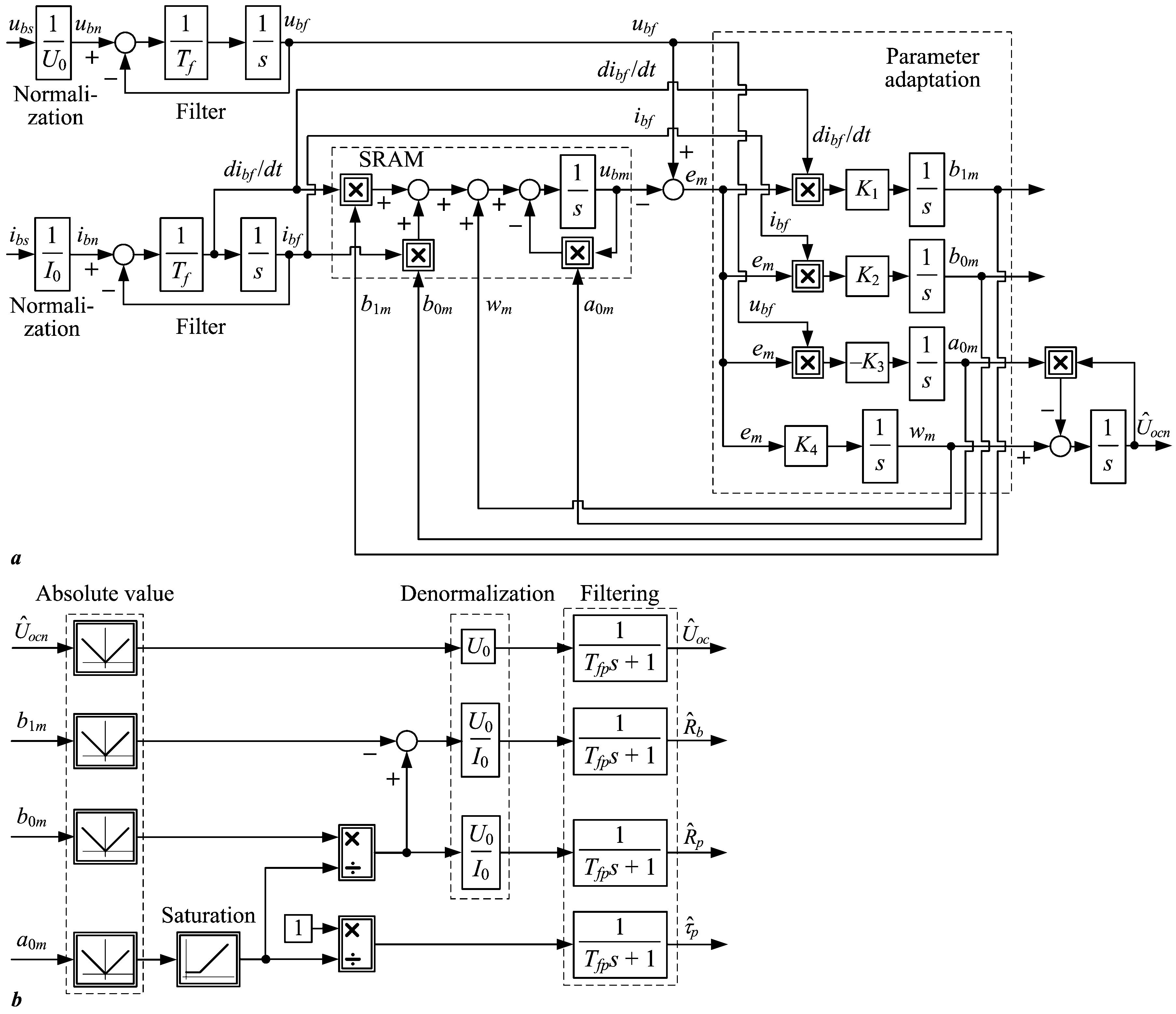
2.5. Parameter Estimator Design Based on the Lyapunov Stability Theory

The battery model parameter estimator design was based on the SRAM identification procedure for linear time-invariant process models [53,57]. It utilizes the system model reference for the minimization of the parameter estimation error, while guaranteeing the global asymptotic convergence of the estimated process parameters. The design of the Lyapunov-based SRAM estimator is based on the battery equivalent circuit model (1), rewritten in the following form:
u b s U o c s = b 1 * s + b 0 * s + a 0 i b s ,
which can then be rewritten as:
U 0 u b n s U o c n s = I 0 b 1 * s + b 0 * s + a 0 i b n s ,
where ubn, Uocn, and ibn represent the normalized battery terminal voltage, battery OCV, and battery current, respectively, and U0 and I0 are battery voltage and current normalization factors, respectively.
The abovementioned model can be refashioned as follows for the SRAM estimator design:
u b n s = b 1 s + b 0 s + a 0 i b n s + U o c n s ,
the following definitions of model coefficients b1, b0, and a0:
b 1 = R b I 0 U 0 , b 0 = R b + R p τ p I 0 U 0 , a 0 = 1 τ p .
Based on the above reformulation of the battery equivalent circuit model, its time-domain representation is:
d u b n d t + a 0 u b n = b 1 d i b n d t + b 0 i b n + w ,
where the slowly varying OCV-related dynamic term can be modeled as a generalized disturbance variable w:
w = d U o c n d t + a 0 U o c n ,
This forms the basis for the SRAM-based estimator of battery equivalent circuit model parameters, which utilizes the copy of the abovementioned process model:
d u b n d t + a 0 m u b n = b 1 m d i b n d t + b 0 m i b n + w m ,
whose parameters a0m, b1m, b0m, and wm are updated online, as shown in Figure 4a.
For the purpose of designing the Lyapunov SRAM parameter estimator for the abovementioned stable process model (a0 > 0 is assumed), the time derivative of the process model input (battery current ib) needs to be calculated. This can be achieved by utilizing a simple first-order state-variable filter (see [57]) of the normalized battery current ibn, as shown in Figure 4a. The same type of filter was applied to the normalized battery voltage ubn in order to match the time lag of the filtered current signal ibf and its time derivative dibf/dt, thus resulting in the final dynamic model with an estimated battery voltage ubm regarded as the output and the filtered current ibf regarded as the input of the from the adaptive model within the SRAM estimator:
d u b m d t + a 0 m u b m = b 1 m d i b f d t + b 0 m i b f + w m ,
which corresponds to the normalized battery model (17) with filtered input and output variables, i.e., battery current and voltage:
d u b f d t + a 0 u b f = b 1 d i b f d t + b 0 i b f + w ,
Based on the above adaptive model and battery process dynamics definitions (18) and (19), the model prediction error and its time derivative are defined as:
e m = u b f u b m ,
e ˙ m = d u b f d t d u b m d t = a 0 u b f + b 1 d i b f d t + b 0 i b f + w + a 0 m u b m b 1 m d i b f d t b 0 m i b f w m ,
which yields the following prediction error dynamics model:
e ˙ m = a 0 e m + b ˜ 1 d i b f d t + b ˜ 0 i b f + w ˜ a ˜ 0 u b m ,
where the parameter estimation errors b ˜ 1 , b ˜ 0 , a ˜ 0 , and w ˜ in Equation (22) are given as follows:
b ˜ 1 = b 1 b 1 m ,   b ˜ 0 = b 0 b 0 m ,   a ˜ 0 = a 0 a 0 m ,   w ˜ = w w m .
To derive the model adaptation law, an appropriate Lyapunov function candidate needs to be chosen, which must satisfy the positive definiteness criterion over the whole domain of the definition in order to guarantee the asymptotic convergence of the parameter estimates. A typical Lyapunov function candidate for this type of parameter estimation problem would be in the following quadratic form [53]:
V = 1 2 e m 2 + 1 2 K 1 b ˜ 1 2 + 1 2 K 2 b ˜ 0 2 + 1 2 K 3 a ˜ 0 2 + 1 2 K 4 w ˜ 2 ,
whose time derivative reads as follows:
V ˙ = e m e ˙ m + 1 K 1 b ˜ ˙ 1 b ˜ 1 + 1 K 2 b ˜ ˙ 0 b ˜ 0 + 1 K 3 a ˜ ˙ 0 a ˜ 0 + 1 K 4 w ˜ ˙ w ˜ .
After inserting the model prediction error and its time derivative from Equations (20) and (22) into Equation (25) and rearranging them, the following final form of the Lyapunov function time derivative is obtained:
V ˙ = a 0 e m 2 + b ˜ 1 e m d i b f d t + b ˜ ˙ 1 K 1 + b ˜ 0 e m i b f + b ˜ ˙ 0 K 2 + a ˜ 0 e m u b m a ˜ ˙ 0 K 3 + w ˜ e m w ˜ ˙ K 4 .
For a stable-dynamics battery process model (characterized by a0 > 0), the first term on the right-hand side of Equation (26) is always negative; therefore, the estimator convergence would be satisfied if and only if the remaining dynamic terms multiplying the parameter estimator errors on the right-hand side of Equation (26) are zero, namely, if [53]:
e m d i b f d t + b ˜ ˙ 1 K 1 = 0 , e m i b f + b ˜ ˙ 0 K 2 = 0 , e m u b m a ˜ ˙ 0 K 3 = 0 ,   e m w ˜ ˙ K 4 = 0 .
Since the actual process model parameters b1, b0, a0, and w are assumed to be constant or very slowly varying, i.e., b ˜ ˙ 1 = b ˙ 1 m , b ˜ ˙ 0 = b ˙ 0 m , a ˜ ˙ 0 = a ˙ 0 m , and w ˜ ˙ = w ˙ m are valid, the model adaptation law is given in the following final form (also shown in Figure 4a):
b 1 m t = b 1 m 0 + K 1 0 t e m τ d i b f d t τ d τ ,
b 0 m t = b 0 m 0 + K 2 0 t e m τ i b f τ d τ ,
a 0 m t = a 0 m 0 K 3 0 t e m τ u b m τ d τ ,
w m t = w m 0 + K 4 0 t e m τ d τ ,
which is globally asymptotically stable for K1 > 0, K2 > 0, K3 > 0 and K4 > 0 [53], and whose convergence is assured under ample and persistent excitation conditions [57].
The physical parameters of the battery transfer function model (i.e., series resistance Rb, polarization resistance Rp, and polarization time constant τp) are subsequently reconstructed, as shown in Figure 4b, based on the following relationships derived from (14):
R ^ b t = b 1 m t U 0 I 0 ,
R ^ p t = b 0 m t a 0 m t b 1 m t U 0 I 0 ,
τ ^ p t = 1 a 0 m t .
Based on the estimation of the generalized disturbance wm and parameter a0m within the adaptive model, the OCV estimate Ûoc is reconstructed in the open-loop manner (Figure 4b) and is used (after de-normalization) as OCV feedback within the CCCV-OCV strategy:
U ^ o c n t = 0 t w m τ a 0 m τ U ^ o c n τ d τ ,
U ^ o c t = U 0 U ^ o c n t .
The battery model parameter reconstruction in Figure 4b using the SRAM-based adaptive model in Figure 4a included sign removal from the parameter estimates (a0m, b1m, b0m, and wm) because these parameters were all positive-valued within the battery model, as well as the lower value saturation of parameter a0m because it could not take a zero value (a0m > 0). Finally, the reconstructed physical parameters of the battery model were low-pass filtered by means of first-order filters (all with the time constant Tfp) to obtain smooth (noise-free) parameter estimates.

3. Simulation Results

The proposed concept of an adaptive SRAM-based estimator and its application to battery charging control were verified by means of simulations using the existing nonlinear model of a LiFePO4 battery cell implemented within the MATLAB/Simulink environment.

3.1. Control System Robustness Analysis

Figure 5a shows the OCV vs. SoC curve gradient Kξ (see Equation (8)) for the particular LiFePO4 battery cell (cf. Figure 1c), which was used in the linearization of the OCV control loop based on the SRAM parameter estimator. Clearly, the OCV vs. SoC gradient value adopts on a wide range of values, thus affecting the overall closed-loop dynamics of the OCV control loop. Figure 5b,c show the root locus plots of the OCV control loop without a voltage-limiting controller being activated for the maximum and minimum values of OCV vs. SoC curve gradient Kξ, respectively, with the open-circuit voltage PI controller tuned with the maximum Kξ gradient value to facilitate robust closed-loop behavior, as indicated in Section 3.3. The comparative root locus plots show that the resulting closed-loop systems are characterized by well-damped closed-loop behavior, with the poles of the linearized closed-loop system being characterized by favorable damping ratios (ζ ≈ 0.5 or higher), even in the case of the notable mismatch of the parameter estimator equivalent lag Tee (±50 of the nominal value). Finally, the stability of the closed-loop system with both OCV and voltage-limiting PI controllers was also analyzed by means of comparative root locus plots, which are shown in Figure 5d for the case of the robust tuning of both controllers (with maximum values of Kξ and Rb parameters) and no variations in the parameter estimator equivalent lag Tee from the nominal value. The root locus plots in Figure 5d indicate that the introduction of the auxiliary voltage-limiting control loop does not significantly affect the overall closed-loop system stability. Thus, it may be surmised that the proposed dual-controller closed-loop system is quite robust to process parameter variations.

3.2. Illustration of Parameter Estimator Convergence

The adaptive SRAM-based estimator of battery model parameters was tested first using the linear time-invariant (LTI) model in Equation (1), whose parameters are listed in Table 1. A pseudo-random binary sequence (PRBS) plus DC offset test signal (current ib) was fed to the battery LTI model and used to provide the SRAM-based parameter estimator with ample excitation. A PRBS signal with the amplitude of a 20 A peak-to-peak, sampling period TPRBS = 8 s, depth of 6 bits (sequence length 26 = 64 distinct states before repetition), and a DC offset of 70 A was used herein, similar to the case of online parameter estimation during charging control.
The battery model simulation responses (current ib and terminal voltage ub) from the idle state (initial polarization voltage up(0) = 0 V) are shown in Figure 6a. These results show that there is an initial lag in the battery terminal voltage response due to polarization voltage dynamics (τp = 24 s), after which the battery voltage establishes a stable limit-cycle due to periodic excitation by the PRBS test signal. Figure 6b shows the comparative results of battery model parameter estimation using the SRAM approach, where the first-order state-variable filter was used to extract the current time derivative and match the battery voltage lag (Figure 4a) has the time constant Tf = 1 s. Filtering of the estimated parameters was also performed by first-order low-pass filters with the time constant Tfp = 1 s (see Figure 4b) to smooth out the parameter estimates. The estimated parameter traces of Rb, Rp, and τp showed good accuracy values for the final estimate (they were initially mismatched with respect to actual values by 10%) with rapid initial convergence, and subsequently slower convergence when reaching the actual values. Top-right plot in Figure 6b shows the response of the OCV estimate from the initial state (set to zero within the parameter estimator). The speed of convergence of the OCV, which represents an unknown offset parameter within the SRAM model, depends on the choice of the update gains K1, … K4. These are obviously a trade-off between the response speed of the OCV estimate and the parameter estimator response damping. The middle case (K1 = 5·10−3, K2 = K3 = 10−6, K4 = 5·10−4) was used in the subsequent tuning of the parameter estimator within the adaptive charging control system. Based on the properties of the OCV estimate response in Figure 6b, the equivalent estimator lag (time constant Tee) was approximately estimated to Tee ≈ 1 min (60 s), and this value was used in OCV PI controller tuning according to Equations (9) and (10).

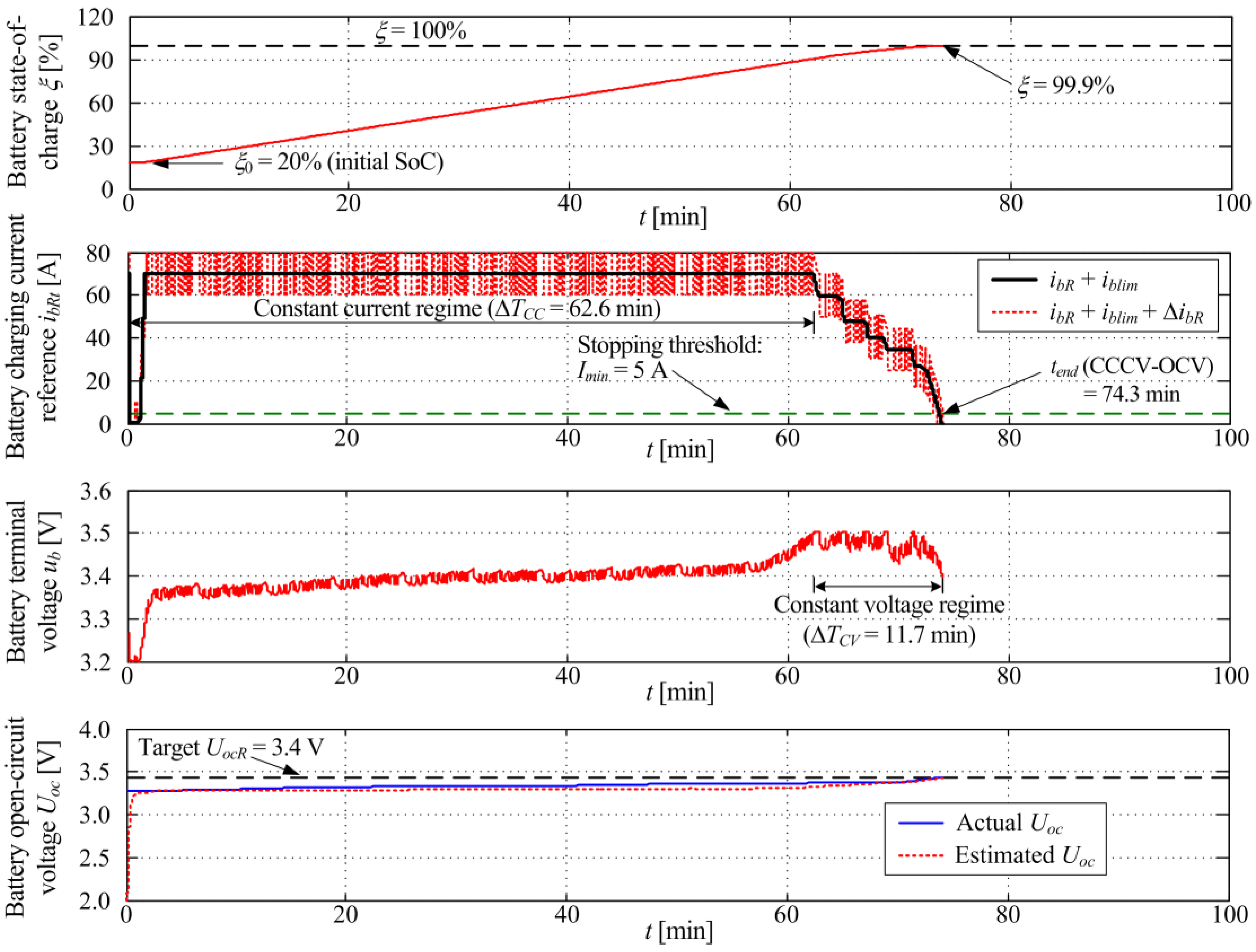
3.3. Charging Control Strategy Results

The proposed adaptive model-based battery charging control system (CCCV-OCV) was verified against the conventional CCCV-VL control strategy [50] by means of simulations using the existing model of a LiFePO4 battery cell [20] implemented within the MATLAB/Simulink environment, with key parameters of both simulation scenarios listed in Table 2, whereas the parameters of the control and estimation strategies used in the comparative simulation analysis are listed in Table 3. The presented simulation scenario corresponded to battery cell recharging from the initial deeply discharged state (characterized by battery SoC of 20 %) to a fully-charged state (with battery SoC target set to 100%). This represents a kind of “ideal” case study (see e.g., [30]), which is intended to illustrate the advantages of the adaptive charging scheme (CCCV-OCV) proposed herein. Naturally, in real-life applications related to EV battery charging, the goal would be to recharge the battery up to 80–90% to avoid a constant-voltage operating regime characterized by low charging-current values and relatively long durations with respect to additional charge gain compared to the constant-current charging regime [32]. It should also be noted that the battery terminal voltage-limiting values ublim for CCCV-VL and CCCV-OCV control strategies were not chosen to be the same. This discrepancy was the direct consequence of the CCCV-OCV strategy having an additional degree of freedom in controlling the battery terminal voltage through the additional OCV estimation-based feedback control action. More precisely, the battery terminal voltage limit ublim and the OCV target UocR were effectively decoupled within the CCCV-OCV control strategy, whereas, in the case of the CCCV-VL control strategy, the same battery terminal voltage limit also served as indirect OCV target (which was only valid when battery current approached zero). Of course, the battery limit voltage values for both the CCCV-VL and CCCV-OCV control strategies were set to lower values (ublim = 3.4 V in the former case and ublim = 3.5 V in the latter case) compared to the maximum safe terminal voltage of 3.65 V listed in the manufacturer’s technical data [20], which would also be performed in actual applications for safety reasons.
As stated above, the CCCV-VL control strategy results from [50] were used as the benchmark, and these results are shown in Figure 7 for the case of the battery terminal voltage limit ublim set to 3.4 V, which corresponds to the fully-charged battery OCV, i.e., Uoc(ξ = 100%). The state-of-charge simulation trace in the top plot in Figure 7 shows that the battery SoC practically reaches the fully charged state at the end of the charging process (ξ ≈ 99.6%), where the small error of final SoC is attributed to the end-of-charging condition, i.e., battery current value dropping below the lower threshold Imin = 5 A (upper middle plot in Figure 7). The battery charging current simulation traces show that the constant-current regime characterized by the upper current limit Imax = 70 A is maintained only during the first 21.5 min. The remainder of the charging process (ending at t = 97.7 min) is conducted in the constant voltage regime (lower middle plot in Figure 7), with the battery terminal voltage limited to ublim = 3.4 V. The OCV trace also confirmed that the battery asymptotically approached the fully charged state with the final reached value Uoc = 3.38 V.
Figure 8 shows the simulation results of the proposed CCCV-OCV control strategy with an adaptive model-based online estimation of the battery open-circuit voltage using a PRBS test signal ΔibR with the peak-to-peak amplitude of 20 A, sampling period TPRBS = 8 s, and 6-bit depth. The CCCV-OCV control strategy was characterized by the battery OCV target UocR = 3.4 V and terminal voltage limit ublim = 3.5 V, thus allowing for an additional degree of freedom during the recharging process. The OCV estimate provided by the SRAM approach can follow the actual OCV value quite accurately after the initial response transient, and results in the close matching of the target OCV (UocR) at the end of the charging process. Moreover, the proposed adaptive charging CCCV-OCV strategy results in an effective speed-up of the charging process when compared to the CCCV-VL benchmark case due to the constant-current regime being maintained for longer than 62.6 min. This, in turn, results in the final battery SoC (99.9%) being reached within 74.3 min (top plot in Figure 8), which corresponds to approximately 23.9% speed-up of the overall charging process, with the battery terminal voltage limit ublim = 3.5 V being maintained only in the final phase of the charging process (11.7 min overall). These results clearly indicate that, by using the proposed dual-controller structure, along with the adaptive OCV estimator, a more effective battery charging process can be facilitated compared to the conventional CCCV-VL approach.
The above results clearly illustrate the main advantages of the CCCV-OCV control strategy over the conventional CCCV-VL control strategy in terms of additional control action flexibility (adjustment of battery terminal voltage) to prolong the constant-current regime due to the decoupling of the battery OCV target and battery terminal voltage limit, which the CCCV-VL strategy does not possess.

4. Discussion of Obtained Results and Comparison with Other Methods

The presented simulation results in Figure 7 and Figure 8 show that both the benchmark control strategy (CCCV-VL) and proposed adaptive control strategy based on the battery OCV estimation (CCCV-OCV) can accurately recharge the battery to within less than 0.4% of the fully charged battery SoC. The adaptive CCCV-OCV charging strategy was able to achieve a 23.9% speed-up when compared to the CCCV-VL strategy benchmark case when recharging from 20% SoC to the fully charged battery state (100% SoC). The CCCV-OCV strategy was able to achieve this due to the accurate following of the actual battery OCV in real time, thus adapting the charging current and achieving a prolonged operation in the constant current regime (about a three-times-longer constant-current regime compared to the conventional CCCV-VL charging strategy).
However, to fully assess the benefits of the adaptive CCCV-OCV charging strategy proposed herein, it would also need to be compared with other charging strategies from the available literature, as suggested in [50]. Table 4 summarizes the relative speed-ups of the charging processes for different charging techniques with respect to the traditional CCCV technique. The CCCV-OCV control strategy proposed herein can easily surpass the charging performance of the fuzzy logic-based charging strategy [34], the MPC-based charging strategy [35], and, to some extent, the MCC charging strategy from [37]. Although the CCCV-OCV method is less effective when compared to offline optimization-based strategies presented in [36] and [37], these strategies usually require significant numerical processing power to conduct online optimizations. By comparing the proposed CCCV-OCV control strategy to the two similar control strategies presented in [41] and [50], it was evident that it did not achieve the same charging speed-up as in the case of the MCC strategy with the LMS-based OCV estimation [41], which relies on extensive an offline optimization of the charging current profile. Even though this would not have been an issue during the real-time implementation of the offline optimized charging current profile, such offline optimizations would have to be repeated whenever a different battery is used within such a charging system. A more faithful comparison of the proposed CCCV-OCV strategy would occur with respect to the case of a conventional CCCV control strategy augmented by an SoC estimate-based charging control (the so-called CCCV-SoC approach) presented in [50] and briefly outlined in Appendix A. Both the CCCV-OCV and CCCV-SoC control strategies presented the following perceived advantages, which may make them suitable for real-time applications: (i) they can be retrofitted to a conventional charging system in a straightforward manner, (ii) they can provide additional feedback about the battery charge level, and (iii) they utilize the inherent ability of the conventional charging system to limit the battery terminal voltage, where the terminal voltage limit can be adjusted so as to facilitate a greater level of flexibility for the charging process.
Figure 9 shows the comparative charging responses of the CCCV-VL, CCCV-SoC, and CCCV-OCV control strategies. The performance of the CCCV-OCV control strategy was very similar to the CCCV-SoC charging strategy from [50], because the CCCV-OCV approach proposed herein was similarly aimed at the straightforward retrofitting of the conventional CCCV charging system using a modular approach, i.e., the introduction of a supervisory (external) battery OCV feedback loop. The main benefit of the proposed CCCV-OCV approach was in its reliance on battery OCV estimation only, rather than the complete nonlinear battery electrical circuit model used within the EKF-based SoC estimator in [50]. Thus, the proposed CCCV-OCV control strategy possesses both the straightforward implementation of the CCCV-SoC control strategy in the form of the cascade control system, and the relative simplicity of the parameter estimator-based supervisory control loop that relies on the well-established OCV vs. SoC relationship.

5. Conclusions

This paper + presented the design of a constant-current/constant-voltage charging control strategy for a battery cell using the so-called cascade control system arrangement with the adaptation of the battery charging current based on the open-circuit voltage (OCV) parameter estimation. The control strategy featured two feedback loops aimed at controlling the battery open-circuit voltage (OCV) parameter towards the target value corresponding to a 100% battery SoC, while simultaneously honoring the predefined battery terminal voltage constraint. The former requirement was realized by using the so-called system reference adaptive model (SRAM) parameter estimator designed according to the Lyapunov stability theory. Since the proposed modification superimposed an additional control level to the existing conventional control strategy, it could be retrofitted to the existing CCCV charging systems in a straightforward manner. The proposed dual-controller voltage control system design was based on the damping optimum criterion, yielding straightforward analytical controller-tuning rules.
The proposed CCCV-OCV charging control strategy was verified against the conventional CCCV-VL charging control system using a battery terminal voltage-limiting controller by means of simulations using the experimentally identified model of a lithium iron phosphate (LiFePO4) battery cell. The simulation results sho that the CCCV-OCV control strategy has a distinct advantage over the more traditional CCCV-VL charging strategy due to the former having an additional degree of freedom through its simultaneous control of battery OCV and independent battery terminal voltage limitation. The CCCV-OCV strategy was able to: (i) maintain a constant-current charging regime three-fold longer compared to the conventional charging strategy and (ii) reduce the charging duration by about 23.9% compared to the conventional (CCCV-VL) strategy. The latter result is in agreement with the previous findings related to the utilization of a state estimator-based superimposed feedback loop with the conventional charging system from [50]. The proposed CCCV-OCV control strategy was apparently less effective in terms of charging speed-up, when compared to offline optimization-based battery charging systems. However, its modular design and straightforward tuning makes it suitable for retrofitting conventional CCCV control systems. The proposed CCCV-OCV control strategy was also shown to be robust to variations in the OCV vs. SoC curve gradient (process model gain) and parameter estimator equivalent lag.
Future studies will be directed towards the practical implementation of the proposed charging control strategy, with emphasis on the applicability to other battery chemistries, and its subsequent experimental verification of the dedicated battery testing experimental setup that is under development, at present, which will be suitable for testing state-of-the-art battery cells, such as those based on LiFePO4 and lithium-titanate (LTO) chemistries.

Author Contributions

Conceptualization, D.P. and J.K.; methodology, J.K. and D.P.; software, M.C. and M.K.; validation, D.P., J.K. and M.C.; formal analysis, J.K. and D.P.; investigation, M.K.; resources, D.P.; writing—original draft preparation, D.P. and M.C.; writing—review and editing, J.K., D.P. and M.K.; visualization, M.C.; supervision, D.P.; project administration, D.P.; funding acquisition, D.P. and M.C. All authors have read and agreed to the published version of the manuscript.

Funding

This research was funded by the European Commission through the Horizon 2020 project “Maximizing the impact of innovative energy approaches in the EU islands” (INSULAE) and the European Regional Development Fund under the grant KK.01.1.1.04.0010 (HiSkid).

Data Availability Statement

Research data can be made available for non-profit use in research and education upon a formal request made to the corresponding author.

Conflicts of Interest

The authors declare no conflict of interest.

Appendix A

Figure A1a shows the control system structure utilizing the estimated battery state-of-charge value provided by the nonlinear state estimator in the form of an extended Kalman filter (EKF), whose block diagram representation is shown in Figure A1b. Both the state estimator-based control strategy (denoted CCCV-SoC herein) and the EKF-based state estimator are described in detail in [50]. The auxiliary battery terminal voltage-limiting controller in Figure A1a performs the same function as in the cases of CCCV-VL and CCCV-OCV control strategies, i.e., the CCCV-OCV and CCCV-SoC strategies represent straightforward extensions of conventional (CCCV-VL) control strategies by means of an additional feedback loop, which conditions (adapts) the battery charging current reference.
Figure A1. Charging control system based on state-of-charge estimation with state-of-charge and battery terminal voltage-limiting controllers (a) and principal block diagram of an EKF-based battery state-of-charge estimator (b).
Wevj 14 00155 g0a1

References

  1. McCollum, D.; Krey, V.; Kolp, P.; Nagai, Y.; Riahi, K. Transport electrification: A key element for energy system transformation and climate stabilization. Clim. Chang. 2014, 123, 651–664. [Google Scholar] [CrossRef]
  2. Deur, J.; Škugor, B.; Cipek, M. Integration of Electric Vehicles into Energy and Transport Systems, Automatika. J. Control. Meas. Electron. Comput. Commun. 2015, 56, 395–410. [Google Scholar]
  3. Komnos, D.; Tsiakmakis, S.; Pavlovic, J.; Ntziachristos, L.; Fontaras, G. Analysing the real-world fuel and energy consumption of conventional and electric cars in Europe. Energy Convers. Manag. 2022, 270, 116161. [Google Scholar] [CrossRef]
  4. Goodall, G.; Scioletti, M.; Zolan, A.; Suthar, B.; Newman, A.; Kohl, P. Optimal design and dispatch of a hybrid microgrid system capturing battery fade. Optim. Eng. 2019, 20, 179–213. [Google Scholar] [CrossRef]
  5. Chinese, D.; Pinamonti, P.; Mauro, C. A spatially explicit optimization model for the selection of sustainable transport technologies at regional bus companies. Optim. Eng. 2021, 22, 1921–1954. [Google Scholar] [CrossRef]
  6. Mohanty, A.K.; Perli, S.B. Fuzzy logic based multi-objective approach for optimal allocation of charging stations for electric vehicles, e-Prime—Advances in Electrical Engineering. Electron. Energy 2022, 2, 100089. [Google Scholar]
  7. Cipek, M.; Pavković, D.; Kljaić, Z.; Mlinarić, T.J. Assessment of Battery-Hybrid Diesel-electric Locomotive Fuel Savings and Emission Reduction Potentials based on a Realistic Mountainous Rail Route. Energy 2019, 173, 1154–1171. [Google Scholar] [CrossRef]
  8. Cipek, M.; Pavković, D.; Krznar, M.; Kljaić, Z.; Mlinarić, T.J. Comparative Analysis of Conventional Diesel-Electric and Hypothetical Battery-Electric Heavy Haul Locomotive Operation in terms of Fuel Savings and Emissions Reduction Potentials. Energy 2021, 232, 121097. [Google Scholar] [CrossRef]
  9. Ahmad, S.; Spiryagin, M.; Cole, C.; Wu, Q.; Wolfs, P.; Bosomworth, C. Analysis of positioning of wayside charging stations for hybrid locomotive consists in heavy train operations. Railw. Eng. Sci. 2021, 23, 285–298. [Google Scholar] [CrossRef]
  10. Karlušić, J.; Cipek, M.; Pavković, D.; Šitum, Ž.; Benić, J. Efficiency comparison of different powertrain structures intended for a hybrid skidder by utilizing a novel cascade optimization algorithm, e-Prime—Advances in Electrical Engineering. Electron. Energy 2022, 2, 100079. [Google Scholar]
  11. Di Ilio, G.; Di Giorgio, P.; Tribioli, L.; Bella, G.; Jannelli, E. Preliminary design of a fuel cell/battery hybrid powertrain for a heavy-duty yard truck for port logistics. Energy Convers. Manag. 2021, 243, 114423. [Google Scholar] [CrossRef]
  12. Hoenicke, P.; Ghosh, D.; Muhandes, A.; Bhattacharya, S.; Bauer, C.; Kallo, J.; Willich, C. Power management control and delivery module for a hybrid electric aircraft using fuel cell and battery. Energy Convers. Manag. 2021, 244, 114445. [Google Scholar] [CrossRef]
  13. Peprah, F.; Gyamfi, S.; Effah-Donyina, E.; Amo-Boateng, M. Evaluation of reactive power support in solar PV prosumer grid, e-Prime—Advances in Electrical Engineering. Electron. Energy 2022, 2, 100057. [Google Scholar] [CrossRef]
  14. Udeh, G.T.; Michailos, S.; Ingham, D.; Hughes, K.J.; Ma, L.; Pourkashanian, M. Optimal sizing of a hybrid PV-WT-battery storage system: Effects of split-ST and combined ST + ORC back-ups in circuit charging and load following. Energy Convers. Manag. 2022, 256, 115370. [Google Scholar] [CrossRef]
  15. Pavković, D.; Sedić, A.; Guzović, Z. Oil Drilling Rig Diesel Power-plant Fuel Efficiency Improvement Potentials through Rule-Based Generator Scheduling and Utilization of Battery Energy Storage System. Energy Convers. Manag. 2016, 121, 194–211. [Google Scholar] [CrossRef] [Green Version]
  16. Pavković, D.; Lobrović, M.; Hrgetić, M.; Komljenović, A. A Design of Cascade Control System and Adaptive Load Compensator for Battery/Ultracapacitor Hybrid Energy Storage-based Direct Current Microgrid. Energy Convers. Manag. 2016, 114, 154–167. [Google Scholar] [CrossRef]
  17. Pavković, D.; Cipek, M.; Kljaić, Z.; Mlinarić, T.-J.; Hrgetić, M.; Zorc, D. Damping Optimum-Based Design of Control Strategy Suitable for Battery/Ultracapacitor Electric Vehicles. Energies 2018, 11, 2854. [Google Scholar] [CrossRef] [Green Version]
  18. International Renewable Energy Agency (IRENA): “Road Transport: The Cost of Renewable Solutions”. IRENA’s Costing Study. 2013. Available online: http://www.irena.org/publications (accessed on 15 November 2015).
  19. Omar, N.; Monem, M.A.; Firouz, Y.; Salmien, J.; Smekens, J.; Hagazy, O.; Gaulous, H.; Mulder, G.; Van den Bossche, P.; Coosemans, T.; et al. Lithium Iron Phosphate Based Battery—Assessment of Aging Parameters and Development of Life Cycle Model. Appl. Energy 2014, 113, 1575–1585. [Google Scholar] [CrossRef]
  20. GWL/Power Group: “SE100AHA Cell Specification”. 2015. Available online: https://www.ev-power.eu (accessed on 15 November 2016).
  21. Wai, R.J.; Jhung, S.J. Design of energy-saving adaptive fast-charging control strategy for Li-Fe-PO4 battery module. IET Power Electron. 2012, 5, 1684–1693. [Google Scholar] [CrossRef]
  22. Hussein, A.A.H.; Batarseh, I. A Review of Charging Algorithms for Nickel and Lithium Battery Chargers. IEEE Trans. Veh. Technol. 2011, 60, 830–838. [Google Scholar] [CrossRef]
  23. James, M.; Grummett, J.; Rowan, M.; Newman, J. Application of Pulse Charging Techniques to Submarine Lead-Acid Batteries. J. Power Sources 2006, 162, 878–883. [Google Scholar] [CrossRef]
  24. Chen, M.; Rincón-Mora, G.A. Accurate, Compact, and Power-Efficient Li-Ion Battery Charger Circuit. IEEE Trans. Circuits Syst. Express Briefs 2006, 53, 1180–1184. [Google Scholar] [CrossRef]
  25. Lee, S.; Han, U.; Lee, H. Development of a hybrid battery thermal management system coupled with phase change material under fast charging conditions. Energy Convers. Manag. 2022, 268, 116015. [Google Scholar] [CrossRef]
  26. Chen, L.-R. PLL-Based Battery Charge Circuit Topology. IEEE Trans. Ind. Electron. 2004, 51, 1134–1136. [Google Scholar] [CrossRef]
  27. Chen, L.-R.; Liu, C.-S.; Chen, J.-J. Improving Phase-Locked Battery Charger Speed by Using Resistance Compensated Technique. IEEE Trans. Ind. Electron. 2009, 56, 1205–1211. [Google Scholar] [CrossRef]
  28. Pavković, D.; Lobrović, M.; Hrgetić, M.; Komljenović, A.; Smetko, V. Battery Current and Voltage Control System Design with Charging Application. In Proceedings of the 2014 IEEE Multi-Conference on Systems and Control, Antibes, France, 8–10 October 2014; pp. 1133–1138. [Google Scholar] [CrossRef]
  29. Vermeer, W.; Stecca, M.; Mouli, G.R.C.; Bauer, P. A Critical Review on The Effects of Pulse Charging of Li-ion Batteries. In Proceedings of the 19th IEEE International Power Electronics and Motion Control Conference (PEMC 2021), Gliwice, Poland, 25–29 April 2021; pp. 217–224. [Google Scholar] [CrossRef]
  30. Arabsalmanabadi, B.; Tashakor, N.; Javadi, A.; Al-Haddad, K. Charging Techniques in Lithium-Ion Battery Charger: Review and New Solution. In Proceedings of the 44th Annual Conference of the Industrial Electronics Society (IEEE IECON 2018), Washington, DC, USA, 21–23 October 2018; pp. 5731–5738. [Google Scholar] [CrossRef]
  31. Amanor-Boadu, J.M.; Guiseppi-Elie, A. Improved Performance of Li-ion Polymer Batteries Through Improved Pulse Charging Algorithm. Appl. Sci. 2020, 10, 895. [Google Scholar] [CrossRef] [Green Version]
  32. Huang, X.; Li, Y.; Acharya, A.B.; Sui, X.; Meng, J.; Teodorescu, R.; Stroe, D.-I. A Review of Pulsed Current Technique for Lithium-ion Batteries. Energies 2020, 13, 2458. [Google Scholar] [CrossRef]
  33. Collin, R.; Miao, Y.; Yokochi, A.; Enjeti, P.; von Jouanne, A. Advanced Electric Vehicle Fast-Charging Technologies. Energies 2019, 12, 1839. [Google Scholar] [CrossRef] [Green Version]
  34. Hsieh, G.-C.; Chen, L.-R.; Huang, K.-S. Fuzzy-Controlled Li-Ion Battery Charge System with Active State-of-Charge Controller. IEEE Trans. Ind. Electron. 2001, 48, 585–593. [Google Scholar] [CrossRef]
  35. Zou, C.; Hu, X.; Wei, Z.; Wik, T.; Egardt, B. Electrochemical Estimation and Control for Lithium-Ion Battery Health-Aware Fast Charging. IEEE Trans. Ind. Electron. 2018, 65, 6635–6645. [Google Scholar] [CrossRef]
  36. Jiang, L.; Huang, Y.; Li, Y.; Yu, J.; Qiao, X.; Huang, C.; Cao, Y. Optimization of Variable-Current Charging Strategy Based on SOC Segmentation for Li-ion Battery. IEEE Trans. Intell. Transp. Syst. 2021, 22, 622–629. [Google Scholar] [CrossRef]
  37. Vo, T.T.; Chen, X.; Shen, W.; Kapoor, A. New charging strategy for lithium-ion batteries based on the integration of Taguchi method and state of charge estimation. J. Power Sources 2015, 273, 413–422. [Google Scholar] [CrossRef]
  38. Chen, Z.; Xia, B.; Mi, C.C.; Xiong, R. Loss-Minimization-Based Charging Strategy for Lithium-Ion Battery. IEEE Trans. Ind. Appl. 2015, 51, 4121–4129. [Google Scholar] [CrossRef]
  39. Liu, K.; Li, K.; Ma, H.; Zhang, J.; Peng, Q. Multi-objective optimization of charging patterns for lithium-ion battery management. Energy Convers. Manag. 2018, 159, 151–162. [Google Scholar] [CrossRef]
  40. Lee, K.-T.; Dai, M.-J.; Chuang, C.-C. Temperature-Compensated Model for Lithium-Ion Polymer Batteries with Extended Kalman Filter State-of-Charge Estimation for an Implantable Charger. IEEE Trans. Ind. Electron. 2018, 65, 589–596. [Google Scholar] [CrossRef]
  41. Rai, R.; Gaglani, M.; Das, S.; Panigrahi, T. Multi-Level Constant Current Based Fast Li-Ion Battery Charging Scheme with LMS Based Online State of Charge Estimation. In Proceedings of the 2020 IEEE Kansas Power and Energy Conference (KPEC 2020), Manhattan, KS, USA, 13–14 July 2020. [Google Scholar] [CrossRef]
  42. Lin, Q.; Wang, J.; Xiong, R.; Shen, W.; He, H. Towards a smarter battery management system: A critical review on optimal charging methods of lithium ion batteries. Energy 2019, 183, 220–234. [Google Scholar] [CrossRef]
  43. Wassiliadis, N.; Schneider, J.; Frank, A.; Wildfeuer, L.; Lin, X.; Jossen, A.; Lienkamp, M. Review of fast charging strategies for lithium-ion battery systems and their applicability for battery electric vehicles. J. Energy Storage 2021, 44, 103306. [Google Scholar] [CrossRef]
  44. Xie, W.; Liu, X.; He, R.; Li, Y.; Gao, X.; Li, X.; Peng, Z.; Feng, S.; Feng, X.; Yang, S. Challenges and opportunities toward fast-charging of lithium-ion batteries. J. Energy Storage 2020, 32, 101837. [Google Scholar] [CrossRef]
  45. de Hoog, J.; Jaguemont, J.; Abdel-Monem, M.; Van Den Bossche, P.; Van Mierlo, J.; Omar, N. Combining an Electrothermal and Impedance Aging Model to Investigate Thermal Degradation Caused by Fast Charging. Energies 2018, 11, 804. [Google Scholar] [CrossRef] [Green Version]
  46. Szumanowski, A.; Chang, Y. Battery Management System Based on Battery Nonlinear Dynamics Modeling. IEEE Trans. Veh. Technol. 2008, 57, 1425–1432. [Google Scholar] [CrossRef]
  47. Pavković, D.; Krznar, M.; Komljenović, A.; Hrgetić, M.; Zorc, D. Dual EKF-based State and Parameter Estimator for a LiFePO4 Battery Cell. J. Power Electron. 2017, 17, 398–410. [Google Scholar] [CrossRef] [Green Version]
  48. Mastali, M.; Vasquez-Arenas, J.; Fraser, R.; Fowler, M.; Afshar, S.; Stevens, M. Battery state of charge estimation using Kalman filtering. J. Power Sources 2013, 239, 294–307. [Google Scholar] [CrossRef]
  49. Ceraolo, M.; Lutzemberger, G.; Huria, T. Experimentally-Determined Models for High-Power Lithium Batteries, SAE 2011-01-1365. In Proceedings of the 2011 SAE World Congress, Detroit, MI, USA, 12–14 April 2011. [Google Scholar] [CrossRef] [Green Version]
  50. Pavković, D.; Premec, A.; Krznar, M.; Cipek, M. Current and voltage control system designs with EKF-based state-of-charge estimator for the purpose of LiFePO4 battery cell charging. Optim. Eng. 2022, 23, 2335–2363. [Google Scholar] [CrossRef]
  51. Dey, S.; Mohon, S.; Pisu, P.; Ayalew, B.; Onori, S. Online State and Parameter Estimation of Battery-Double Layer Capacitor Hybrid Energy Storage System. In Proceedings of the IEEE 54th Annual Conference on Decision and Control (CDC 2015), Osaka, Japan, 15–18 December 2015; pp. 676–681. [Google Scholar] [CrossRef]
  52. Pavković, D.; Komljenović, A.; Hrgetić, M.; Krznar, M. Experimental Characterization and Development of a SoC/SoH Estimator for a LiFePO4 Battery Cell. In Proceedings of the IEEE EUROCON 2015, Salamanca, Spain, 8–11 September 2015; pp. 397–402. [Google Scholar] [CrossRef]
  53. Rao, G.P.; Unbehauen, H. Identification of Continuous-Time Systems; IEE Proceedings Control Theory Applications; Springer: Berlin/Heidelberg, Germany, 2006; Volume 153, pp. 185–220. [Google Scholar] [CrossRef]
  54. Roscher, M.A.; Sauer, D.U. Dynamic electric behavior and open-circuit-voltage modeling of LiFePO4-based lithium-ion secondary batteries. J. Power Sources 2011, 196, 331–336. [Google Scholar] [CrossRef]
  55. Naslin, P. Essentials of Optimal Control; Illife Books Ltd.: London, UK, 1968. [Google Scholar]
  56. Schröder, D. Elektrische Antriebe—Regelung von Antriebssystemen, 3rd ed.; Springer: Berlin/Heidelberg, Germany, 2007. [Google Scholar]
  57. Unbehauen, H.; Rao, G.P. Identification of Continuous Systems; North Holland: Amsterdam, The Netherlands, 1987. [Google Scholar]
  58. Isermann, R. Digital Control Systems 1; Springer: Berlin/Heidelberg, Germany, 1989. [Google Scholar]
Figure 1. Battery cell series resistance (a), polarization resistance (b), and open-circuit voltage (c) with respect to state of charge and polarization time constant identification experiment (d).
Wevj 14 00155 g001
Figure 2. Charging control strategy flowcharts: conventional strategy (a) and novel control strategy based on OCV estimation (b).
Wevj 14 00155 g002
Figure 3. Cascade control systems used for battery charging: battery terminal voltage-limiting superimposed controller (a) and open-circuit voltage/battery terminal voltage-limiting dual superimposed controllers (b).
Wevj 14 00155 g003
Figure 4. Battery model parameter estimator based on SRAM approach (a) and reconstruction of battery internal and polarization resistance, polarization time constant, and open-circuit voltage (b).
Wevj 14 00155 g004
Figure 5. Battery cell OCV vs. SoC curve gradient Kξ (a), comparative root locus plots of linearized OCV feedback loop tuned for maximum value of gradient Kξ (b), minimum value of gradient Kξ (c) for different SRAM estimator lags, and comparative root locus plots of charging control systems without and with active voltage-limiting loop (d).
Wevj 14 00155 g005
Figure 6. Simulation results of linear time-invariant battery model with respect to PRBS shape of battery current signal (a) and illustration of SRAM estimator convergence with respect to different choices of update gains (b).
Wevj 14 00155 g006
Figure 7. Simulation results of CCCV-VL charging strategy for battery terminal voltage limit set to ublim = 3.4 V.
Wevj 14 00155 g007
Figure 8. Simulation results of the adaptive CCCV-OCV charging strategy for battery open-circuit voltage target set to UocR = 3.4 V and terminal voltage limit set to ublim = 3.5 V.
Wevj 14 00155 g008
Figure 9. Comparative responses of conventional charging, charging based on SoC estimator, and charging based on the open-circuit voltage (parameter) estimator.
Wevj 14 00155 g009
Table 1. Parameters of linear time-invariant battery model used for parameter estimator validation.
ParameterValue
Battery model series resistance Rb0.7 mΩ
Battery model polarization resistance Rp1.0 mΩ
Battery model polarization time constant τp24 s
Battery model open-circuit voltage Uoc3.2 V
Table 2. Key parameters of the considered simulation scenarios.
ParameterValue
Inner current control-loop lag Tei20 ms
Current/voltage sensor time constant Tfm5 ms
LiFePO4 battery cell charge capacity Qb100 Ah
Battery charging current upper limit Imax70 A
Battery charging turn-off current Imin5 A
Initial battery state of charge ξ020 %
Target battery state of charge ξR100 %
CCCV-VL battery limit voltage value ublim3.4 V
CCCV-OCV open-circuit voltage target value UocR3.4 V
CCCV-OCV battery limit voltage value ublim3.5 V
Table 3. Key parameters of the control strategies under investigation.
ParameterValue
Voltage-limiting PI controller proportional gain Kcl157.8
Voltage-limiting PI controller integral time constant Tcl5.4 ms
OCV PI controller proportional gain Kcu16,325
OCV PI controller integral time constant Tcu44.1 s
SRAM parameter estimator gain K15·10−3
SRAM parameter estimator gain K210−6
SRAM parameter estimator gain K310−6
SRAM parameter estimator gain K45·10−4
SRAM parameter estimator pre-filtering time constant Tf1 s
SRAM parameter estimator post-filtering time constant Tpf5 s
Voltage normalization parameter U03.2 V
Current normalization parameter I0100 A
Control strategy sampling period T4 ms
Table 4. Comparison of different charging strategies in terms of speed-up.
Charging Method and ReferenceSpeed-Up vs. Conventional Charging
Fuzzy logic charging controller [34]13.2%
MCC charging with offline optimization [37]19.1% to 29.7%
MPC with moving horizon estimation [35]17.5%
GA-based offline optimization [36]39.7%
MCC charging with LMS estimator of OCV [41]39.3%
EKF-based SoC estimation plus CCCV (CCCV-SoC) [50]25.0%
SRAM-based OCV estimation plus CCCV (CCCV-OCV)23.9%
Disclaimer/Publisher’s Note: The statements, opinions and data contained in all publications are solely those of the individual author(s) and contributor(s) and not of MDPI and/or the editor(s). MDPI and/or the editor(s) disclaim responsibility for any injury to people or property resulting from any ideas, methods, instructions or products referred to in the content.

