
Design of Permanent Magnet-Assisted Synchronous Reluctance Motor with Low Torque Ripple


Abstract
:1. Introduction
2. Theoretical Analysis of Motor Structure and Cogging Torque
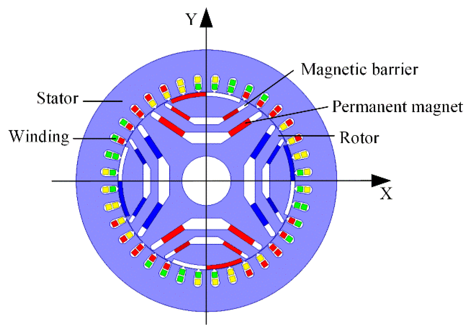
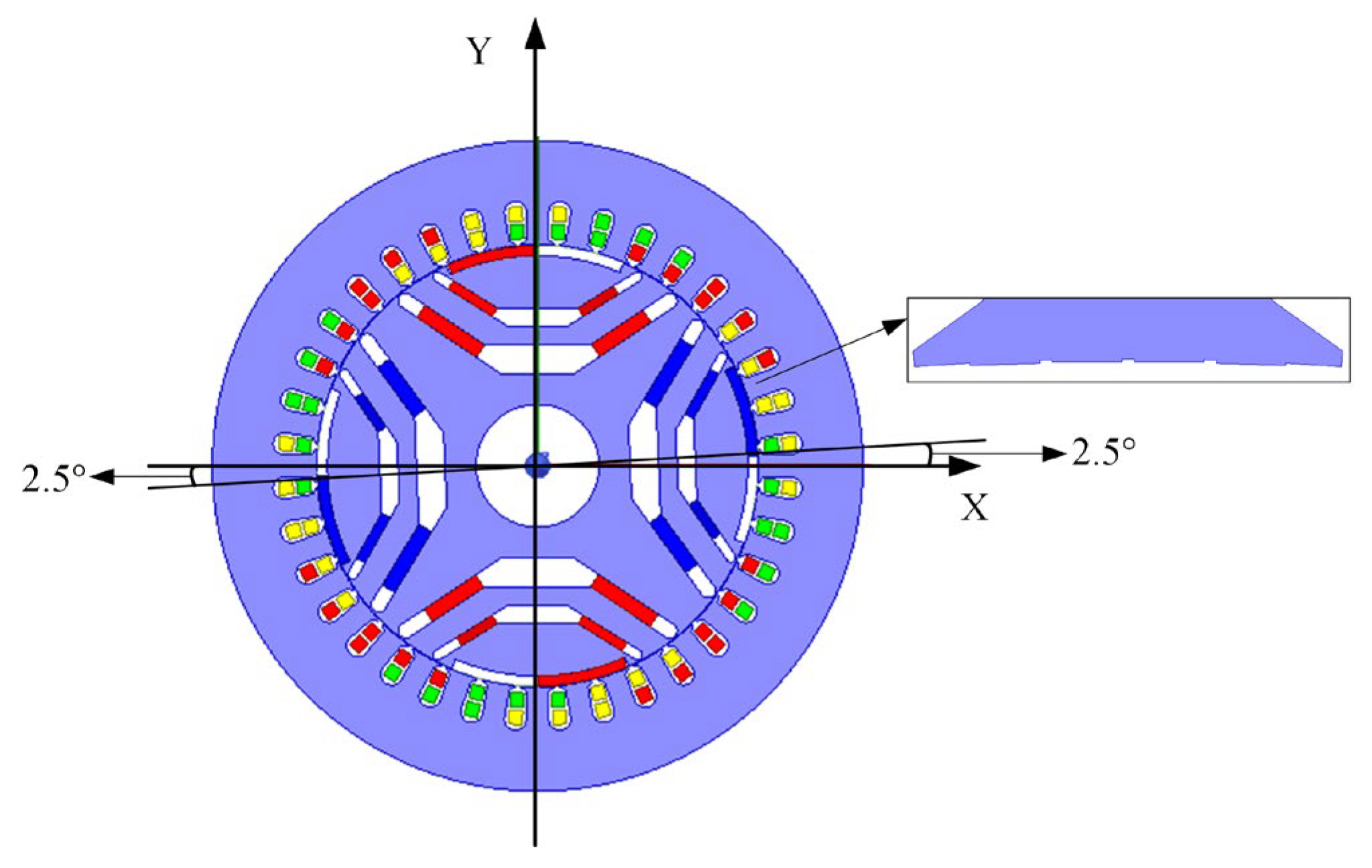
2.1. Motor Structure and Basic Parameters
2.2. Cogging Torque Generation Principle
2.3. Cogging Torque Reduction Principle
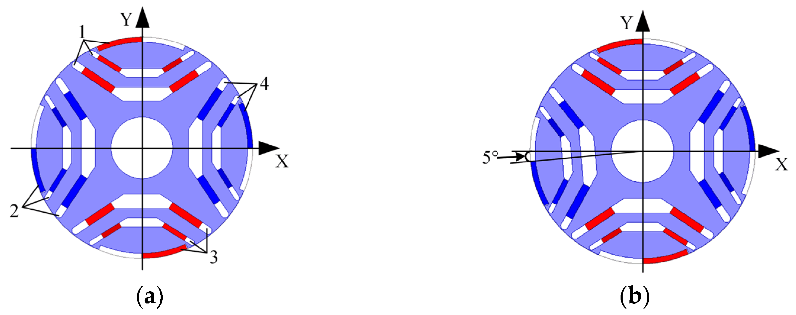
2.3.1. Magnetic Pole Migration Principle
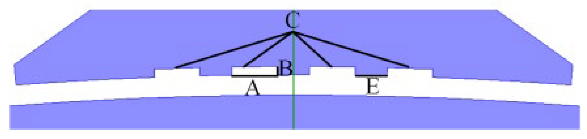
2.3.2. Principle of Stator Auxiliary Slot
3. Motor Structure Design
3.1. Magnetic Pole Migration Structure Design
3.2. Stator Auxiliary Groove Design
3.2.1. Optimize the Selection of Variables
3.2.2. Test Results
3.2.3. Results Processing
- Mean analysis
- (1).
- Population mean analysis
- (2).
- Average value analysis of all variables at all levels
- 2.
- Variance Analysis
4. Motor Performance Analysis
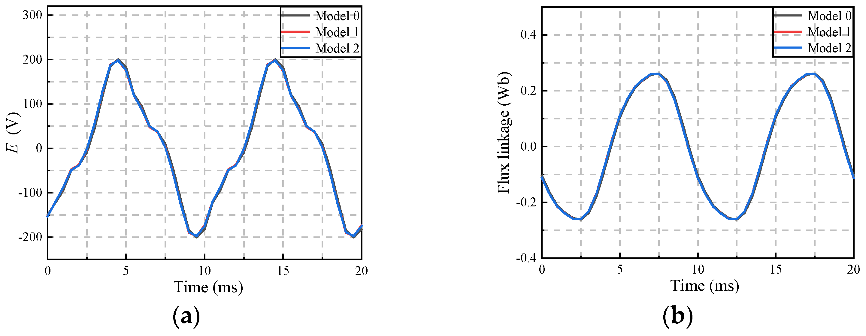
4.1. No-Load Performance Analysis
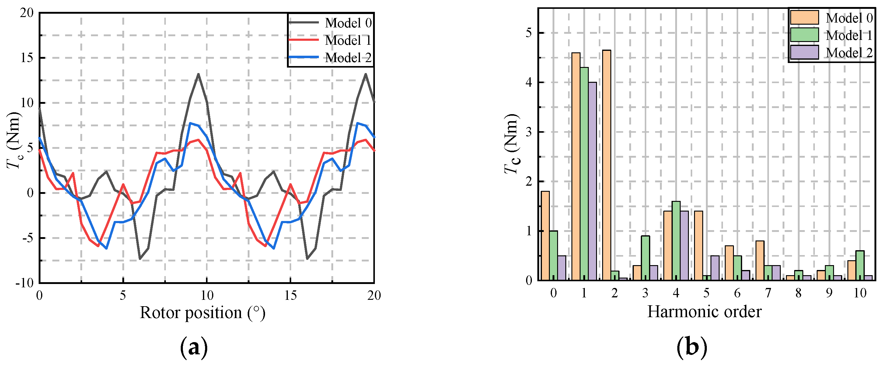
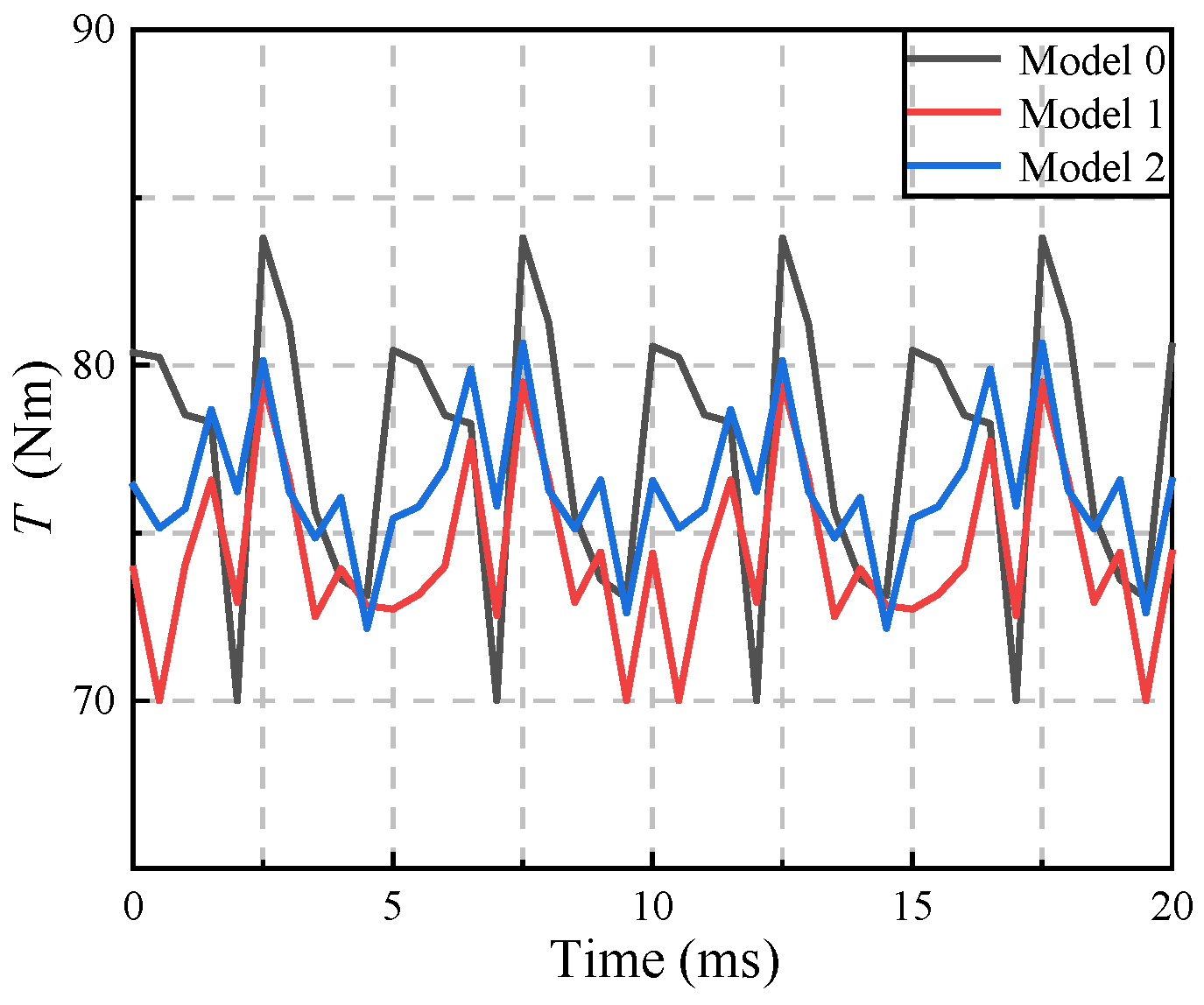
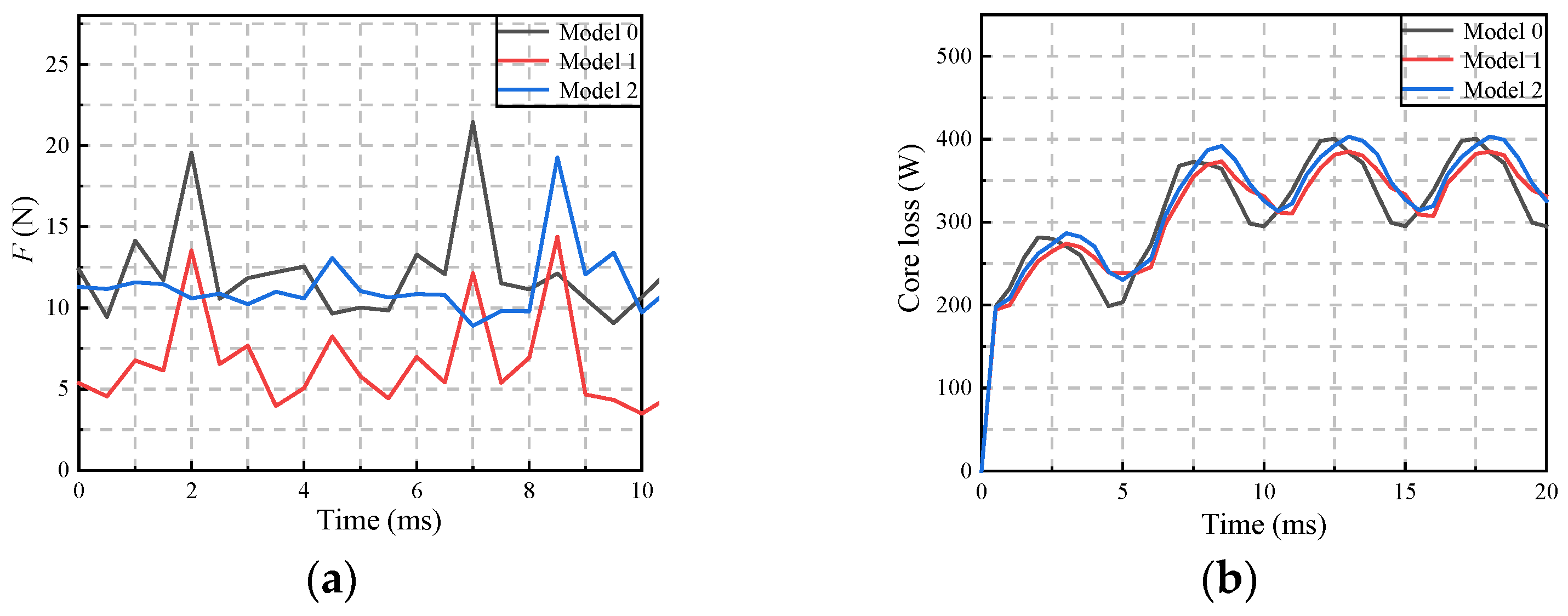
4.2. On-Load Performance Analysis
5. Conclusions
Author Contributions
Funding
Data Availability Statement
Conflicts of Interest
References
- Michele, D.; Mukhammed, M.; Wang, S.; Davide, B.; Giampaolo, B.; Werner, J.; Nicola, B.; Michael, G.; Chris, G. Optimised design of permanent magnet assisted synchronous reluctance machines for household appliances. IEEE Trans. Energy Convers. 2021, 36, 3084–3095. [Google Scholar]
- Liu, X.P.; Li, Y.; Liu, Z.Q.; Ling, T.; Luo, Z.H. Analysis and design of a high power density permanent magnet-assisted synchronous reluctance machine with low-cost ferrite magnets for EVs/HEVs. Compel.-Int. J. Compul. Math. Electr. Electron. Eng. 2016, 35, 1949–1964. [Google Scholar] [CrossRef]
- Guo, H.; He, X.; Xu, J.Q.; Tian, W.; Sun, G.Y.; Ju, L.C.; Li, D.H. Design of an aviation dual-three-phase high-power high-speed permanent magnet assisted synchronous reluctance starter-generator with antishort-circuit ability. IEEE Trans. Power Electron. 2022, 37, 12619–12635. [Google Scholar] [CrossRef]
- Wang, X.H. Permanent Magnet Motor, 2nd ed.; China Electric Power Press: Beijing, China, 2011. [Google Scholar]
- Ueda, Y.; Takahashi, H. Cogging torque reduction on transverse-flux motor with multilevel skew configuration of toothed cores. IEEE Trans. Magn. 2019, 55, 1–5. [Google Scholar] [CrossRef]
- Jo, I.H.; Lee, H.W.; Jeong, G.; Ji, W.Y.; Park, C.B. A study on the reduction of cogging torque for the skew of a magnetic geared synchronous motor. IEEE Trans. Magn. 2019, 55, 1–5. [Google Scholar] [CrossRef]
- Ruan, B.; Gu, A.Y.; Lian, Y.Z.; Hong, Z.C.; Liu, H.; Xu, Z.Y. Optimization design for torque ripple of IPMSM based on taguchi method and magnet shifting. Micromotors 2019, 52, 7–11. [Google Scholar]
- Liu, G.H.; Du, X.X.; Zhao, W.X.; Chen, Q. Reduction of torque ripple in inset permanent magnet synchronous motor by magnets shifting. IEEE Trans. Magn. 2017, 53, 1–13. [Google Scholar] [CrossRef]
- Zhou, Y.; Li, H.S.; Meng, G.W.; Zhou, S.; Cao, Q. Analytical calculation of magnetic field and cogging torque in surface-mounted permanent-magnet machines accounting for any eccentric rotor shape. IEEE Trans. Ind. Electron. 2015, 62, 3438–3447. [Google Scholar] [CrossRef]
- Liang, J.; Dong, Y.; Sun, H.X.; Liu, R.Z.; Zhu, G.T. Flux-barrier design and torque performance analysis of synchronous reluctance motor with low torque ripple. Appl. Sci. 2022, 12, 3958. [Google Scholar] [CrossRef]
- Herlina; Rudy, S.; Uno, B.S. Minimization of cogging torque based on different shape of anti-notch method. In Proceedings of the 2016 3rd International Conference on Information Technology, Computer, and Electrical Engineering (ICITACEE), Semarang, Indonesia, 19–20 October 2016; pp. 160–163. [Google Scholar]
- Huang, Y.; Jiang, L.; Lei, H. Research on cogging torque of the permanent magnet canned motor in domestic heating system. Energy Rep. 2021, 7, 1379–1389. [Google Scholar] [CrossRef]
- Fadranski, D.; Syré, A.M.; Grahle, A.; Göhlich, D. Analysis of charging infrastructure for private, battery electric passenger cars: Optimizing spatial distribution using a genetic algorithm. World Electr. Veh. J. 2023, 14, 26. [Google Scholar] [CrossRef]
- Liu, Z.Y.; Hu, Y.; Wu, J.C.; Zhang, B.Y.; Feng, G.H. A novel modular permanent magnet-assisted synchronous reluctance motor. IEEE Access 2021, 9, 19947–19959. [Google Scholar] [CrossRef]
- Liu, X.T.; Fan, X.J.; Wang, L.; Wu, J. State of charge estimation for power battery base on improved particle filter. World Electr. Veh. J. 2023, 14, 8. [Google Scholar] [CrossRef]
- Yan, S.L.; Zhang, X.Y.; Gao, Z.D.; Wang, A.C.; Zhang, Y.F.; Xu, M.J.; Hua, S.Z. Design optimization of a new hybrid excitation drive motor for new energy vehicles. World Electr. Veh. J. 2023, 14, 4. [Google Scholar] [CrossRef]
- Cheng, P.; Yang, X.J.; Lan, H.; Hong, Y.Y.; Dai, Q. Design and efficiency optimization of a synchronous generator using finite element method and taguchi method. Electr. Mach. Control. 2019, 23, 94–99+104. [Google Scholar]
- Liu, Y.L.; Yu, H.T.; Wang, Y. Establishment of a new dual rotor flux switching motor magnetic circuit model and optimization of no-load back EMF. IEEE Trans. Magn. 2019, 55, 1–5. [Google Scholar] [CrossRef]
- Xu, J.W.; Gao, L.Y.; Zeng, L.B.; Pei, R.L. Optimum design of interior permanent magnet synchronous motor using taguchi method. In Proceedings of the 2019 IEEE Transportation Electrification Conference and Expo (ITEC), Detroit, MI, USA, 19–21 June 2019; pp. 1–4. [Google Scholar]
- Hwang, C.C.; Hung, S.S.; Liu, C.T.; Cheng, S.P. Optimal design of a high speed SPM motor for machine tool applications. IEEE Trans. Magn. 2014, 50, 1–4. [Google Scholar] [CrossRef]
- Xu, M.J.; Zhang, X.Y.; Wang, J.; Yan, S.L.; Yin, H.B.; Zhou, Y.C. Cogging torque reduction method of internal permanent magnat motor based on stator tooth shoulder chamfer. J. Hebei Univ. Sci. Technol. 2021, 42, 561–569. [Google Scholar]


| Parameters | Symbol | Value | Unit |
|---|---|---|---|
| Rated speed | nN | 3000 | r/min |
| Rated current | IN | 42 | A |
| Number of pole Pairs | p | 2 | - |
| Number of slots | z | 36 | - |
| Radius of the stator inner surface | R1 | 90.1 | mm |
| Radius of rotor outer surface | R2 | 89.6 | mm |
| Radius of the stator outer surface | Rs | 132.6 | mm |
| Length of motor | ls | 155 | mm |
| Mode | 0 | 1 | 2 | 3 | |
|---|---|---|---|---|---|
| Performance | |||||
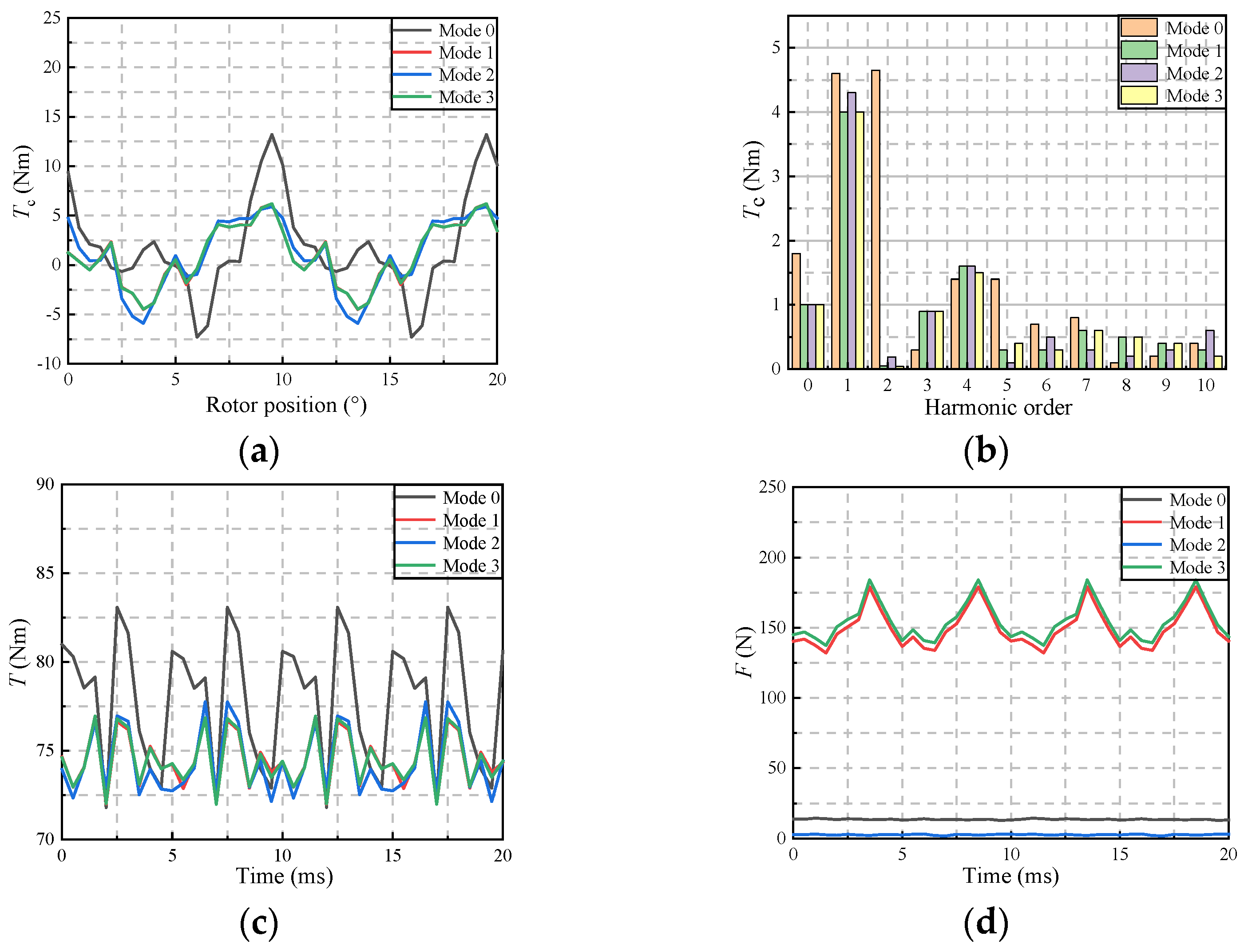
| Tc (Nm) | 13.2 | 6.2 | 5.9 | 6.2 | |
| Tc1 (Nm) | 4.6 | 4 | 4.3 | 4 | |
| Tc2 (Nm) | 4.65 | 0.05 | 0.19 | 0.04 | |
| T (Nm) | 77.6 | 74.5 | 74.34 | 74.54 | |
| Tr (%) | 8.9 | 5.8 | 6.4 | 5.7 | |
| F (N) | 14 | 179 | 3 | 184 | |
| Offset Angle | 0° | 2.5° | 5° | |
|---|---|---|---|---|
| Performance | ||||
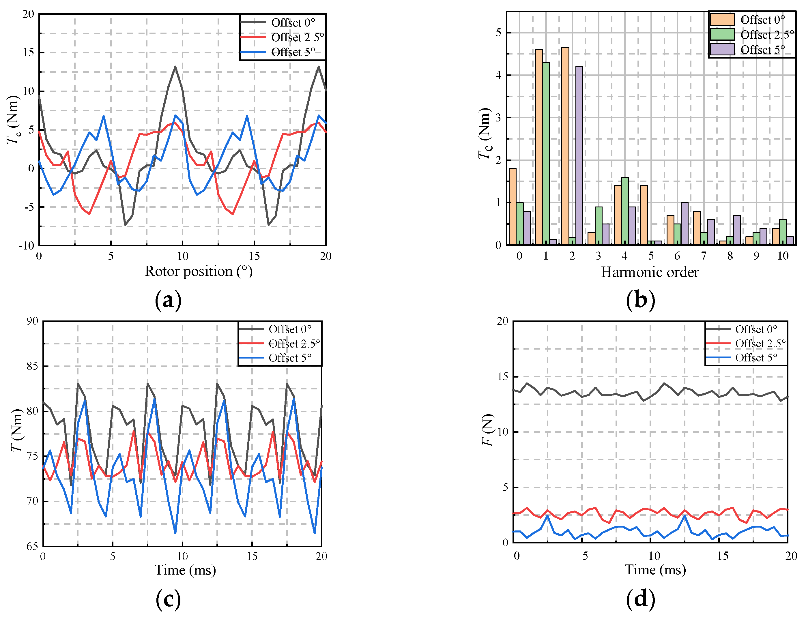
| Tc (Nm) | 13.2 | 5.9 | 6.87 | |
| Tc1 (Nm) | 4.6 | 4.3 | 0.13 | |
| Tc2 (Nm) | 4.65 | 0.19 | 4.21 | |
| T (Nm) | 77.6 | 74.34 | 73.32 | |
| Tr (%) | 8.9 | 6.4 | 12.4 | |
| F (N) | 14 | 3 | 2.4 | |
| Interval | a | b | c | d | |
|---|---|---|---|---|---|
| Number | |||||
| 1 | 0° | 0° | 0° | 0° | |
| 2 | 1° | 2° | 3° | 4° | |
| 3 | 0.5° | 1° | 1.5° | 2° | |
| 4 | 0.25° | 0.5° | 0.75° | 1° | |
| Factor | A (°) | B (mm) | C | D | E | |
|---|---|---|---|---|---|---|
| Level | ||||||
| 1 | 0.35 | −0.2 | 1 | Rectangle | a | |
| 2 | 0.7 | −0.1 | 2 | Triangle | b | |
| 3 | 1.05 | 0.1 | 3 | Arc | c | |
| 4 | 1.4 | 0.2 | 4 | Trapezoid | d | |
| Test Time | A | B | C | D | E |
|---|---|---|---|---|---|
| 1 | 1 | 1 | 1 | 1 | 1 |
| 2 | 1 | 2 | 2 | 2 | 2 |
| 3 | 1 | 3 | 3 | 3 | 3 |
| 4 | 1 | 4 | 4 | 4 | 4 |
| 5 | 2 | 1 | 2 | 3 | 4 |
| 6 | 2 | 2 | 1 | 4 | 3 |
| 7 | 2 | 3 | 4 | 1 | 2 |
| 8 | 2 | 4 | 3 | 2 | 1 |
| 9 | 3 | 1 | 3 | 4 | 2 |
| 10 | 3 | 2 | 4 | 3 | 1 |
| 11 | 3 | 3 | 1 | 2 | 4 |
| 12 | 3 | 4 | 2 | 1 | 3 |
| 13 | 4 | 1 | 4 | 2 | 3 |
| 14 | 4 | 2 | 3 | 1 | 4 |
| 15 | 4 | 3 | 2 | 4 | 1 |
| 16 | 4 | 4 | 1 | 3 | 2 |
| Test Time | T (Nm) | Tr (%) |
|---|---|---|
| 1 | 74.46 | 6.5 |
| 2 | 75.74 | 7.8 |
| 3 | 74.14 | 7.56 |
| 4 | 73.92 | 7.36 |
| 5 | 76.34 | 8.6 |
| 6 | 76.16 | 7.32 |
| 7 | 74.88 | 6.54 |
| 8 | 75.36 | 7.6 |
| 9 | 76.7 | 7.27 |
| 10 | 76.23 | 5.57 |
| 11 | 74.02 | 7.8 |
| 12 | 75.64 | 6.5 |
| 13 | 76.64 | 7.3 |
| 14 | 76.88 | 5.7 |
| 15 | 75.34 | 5.47 |
| 16 | 75.48 | 6.9 |
| Factor | Level | mT (Nm) | mTr (%) |
|---|---|---|---|
| A | 1 | 74.57 | 7.3 |
| 2 | 75.69 | 7.5 | |
| 3 | 75.65 | 6.78 | |
| 4 | 76.1 | 6.3 | |
| B | 1 | 76 | 7.4 |
| 2 | 76.25 | 6.6 | |
| 3 | 74.6 | 6.8 | |
| 4 | 75.1 | 7.1 | |
| C | 1 | 75 | 7.13 |
| 2 | 75.76 | 7.09 | |
| 3 | 75.77 | 7.03 | |
| 4 | 75.4 | 6.7 | |
| D | 1 | 75.46 | 6.3 |
| 2 | 75.44 | 7.6 | |
| 3 | 75.55 | 7.16 | |
| 4 | 75.5 | 6.86 | |
| E | 1 | 75.35 | 6.285 |
| 2 | 75.7 | 7.13 | |
| 3 | 75.6 | 7.17 | |
| 4 | 75.3 | 7.365 |
| Factor | ST | STr |
|---|---|---|
| A | 0.32 | 0.22 |
| B | 0.45 | 0.1 |
| C | 0.1 | 0.02 |
| D | 0.001 | 0.22 |
| E | 0.03 | 0.17 |
| Factor | KSTx (%) | KSTrx (%) |
|---|---|---|
| A | 35.5 | 30.1 |
| B | 50 | 13.7 |
| C | 11.1 | 27.4 |
| D | 0.1 | 30.13 |
| E | 3.3 | 23.3 |
| Model | 0 | 1 | 2 | |
|---|---|---|---|---|
| Performance | ||||
| Back EMF | fundamental amplitude | 170 V | 169.6 V | 169.9 V |
| THD | 22.03% | 21.25% | 20.96% | |
| Flux linkage | fundamental amplitude | 0.27 Wb | 0.27 Wb | 0.27 Wb |
| THD | 7.29% | 7.26% | 7.17% |
| Model | 0 | 1 | 2 | |
|---|---|---|---|---|
| Performance | ||||
| Electromagnetic torque | 77.6 Nm | 74.34 Nm | 76.32 Nm | |
| Torque ripple | 8.9% | 6.4% | 5.5% | |
Disclaimer/Publisher’s Note: The statements, opinions and data contained in all publications are solely those of the individual author(s) and contributor(s) and not of MDPI and/or the editor(s). MDPI and/or the editor(s) disclaim responsibility for any injury to people or property resulting from any ideas, methods, instructions or products referred to in the content. |
© 2023 by the authors. Licensee MDPI, Basel, Switzerland. This article is an open access article distributed under the terms and conditions of the Creative Commons Attribution (CC BY) license (https://creativecommons.org/licenses/by/4.0/).
Share and Cite
Li, X.; Sun, Z.; Sun, W.; Guo, L.; Wang, H. Design of Permanent Magnet-Assisted Synchronous Reluctance Motor with Low Torque Ripple. World Electr. Veh. J. 2023, 14, 82. https://doi.org/10.3390/wevj14040082
Li X, Sun Z, Sun W, Guo L, Wang H. Design of Permanent Magnet-Assisted Synchronous Reluctance Motor with Low Torque Ripple. World Electric Vehicle Journal. 2023; 14(4):82. https://doi.org/10.3390/wevj14040082
Chicago/Turabian StyleLi, Xinmin, Zihan Sun, Wenbo Sun, Liyan Guo, and Huimin Wang. 2023. "Design of Permanent Magnet-Assisted Synchronous Reluctance Motor with Low Torque Ripple" World Electric Vehicle Journal 14, no. 4: 82. https://doi.org/10.3390/wevj14040082