
Smooth Switching Method for Multi-Mode Synchronous Space Vector Modulation of NPC Three-Level Inverter


1
School of Electrical Engineering, Tiangong University, Tianjin 300387, China
2
Advanced Electrical Equipment Innovation Center, Zhejiang University, Hangzhou 311107, China
*
Author to whom correspondence should be addressed.
World Electr. Veh. J. 2023, 14(3), 62; https://doi.org/10.3390/wevj14030062
Submission received: 8 February 2023
/
Revised: 25 February 2023
/
Accepted: 27 February 2023
/
Published: 1 March 2023
Abstract
:To meet the requirements of output harmonic distortion of neutral point clamped (NPC) three-level inverter under low switching frequency conditions, multi-mode synchronous space vector modulation is usually adopted. When switching between different pulse patterns, there will be oscillation in the output current. This paper proposes a smooth switching method for synchronous space vector modulation. This method compensates the phase angle of the reference voltage vector, in order to make the flux trajectories continuous before and after switching. Multi-position smooth switching can be realized in the fundamental period, and there is no delay in switching. Compared with direct switching, the total harmonic distortion rate of current during switching is reduced. The calculation of the phase angle compensation value of the reference voltage vector is not affected by the specific parameters and operating conditions of the motor, and can be carried out offline. Finally, experiments are carried out on a 7.5 kW induction motor fed by NPC three level inverter to verify the feasibility and effectiveness of the proposed method.
1. Introduction
NPC three-level inverter has the advantages of low voltage stress, low switching loss and low harmonic distortion. It is widely used in high-power medium-voltage applications such as locomotive traction and pumping systems [1,2,3]. In order to continuously improve the performance level of the converter, many scholars have also conducted in-depth research on common mode voltage suppression [4,5], fault diagnosis [6], rapid dynamic control [7], loss reduction and efficiency increase [8]. Due to switching losses and heat dissipation limitations, the switching frequency fs of the inverter is only a few hundred hertz [9,10]. However, the range of output fundamental frequency fe is wide, resulting in a large change in pulse number P = fs/fe. To solve the above problem, asynchronous modulation is usually used in the low fundamental frequency region. While in the middle and high fundamental frequency region, multi-mode synchronous modulation is often adopted to ensure the synchronization and symmetry of the output waveform [11].
The synchronous modulation methods mainly include: the selective harmonic elimination pulse width modulation (SHE-PWM) [12,13], current harmonic minimum pulse width modulation (CHM-PWM) [14], synchronized space vector pulse width modulation (SSVM) [15,16]. For SHW-PWM and CHMPWM, Fourier decomposition is applied to establish the equation of switching angles for the harmonic distortion minimization. However, in order to obtain the switching angle, nonlinear transcendental equations need to be solved. When applied to motor loads with rapidly changing operating conditions, the amount of calculations will increase greatly. It will put forward higher requirements for the calculation ability of the controller if the switching angles are calculated online [13]. It is necessary to use high-performance computers for complex iterative solutions, which greatly increases the difficulty of real-time calculation. It is difficult to adapt to variable operating conditions if the switching angles are calculated offline.
The principle of SSVM is approximately the same as that of asynchronous space vector modulation, the main difference is that the switching sequence needs to satisfy synchronization and symmetry. In industrial applications, the acceleration and deceleration of the motor is frequent. The range of fundamental frequency is large, the pulse number is not constant. In order to meet the limitation of the maximum switching frequency of the wide fundamental frequency range inverter, the multi-mode SSVM method need to be adopted. When switching between different pulse patterns, the fundamental phase angle is discontinuous due to the mutation of the switching frequency. Thus, there are oscillations in the output current.
In [17], a zero-crossing point voltage comparison method is proposed for the switching between different pulse patterns. This method is easy to be realized, but the switching points are few and far between in each fundamental period. However, there are still oscillations in the output current during the switching between different pulse patterns. In [18,19], the harmonic flux trajectories and the actual flux trajectories between and after pulse pattern switching are analyzed, the switching angle at which the flux trajectories do not change during pulse pattern switching is found and used as the switching point. The above method does not depend on the modulation mode. However, the number of switching points in each fundamental period is still less, and the flux trajectories ripple cannot be completely eliminated during the pulse pattern switching. In [20,21], the current harmonic characteristic of different modulation methods during pulse pattern switching are analyzed, the switching point with similar harmonic spectrum is selected to reduce the current ripple. However, the switching point of this method needs to be obtained by trial and error of the simulation model, and the theoretical basis of this method is absent. In [22], the switching points are set at the position where there is no switching in all the three phases when switching between different pulse patterns. However, there are still fewer switching points of the proposed switching method.
The pulse patterns are all switched at fixed angles for all the above methods. The switching points are less and the flux trajectories will be oscillated. References [17,20,21,22] only analyzed and verified the harmonic performance of the modulation strategy in steady state, and did not analyze the harmonic performance during switching. References [18,19] did not show the harmonic performance of the modulation method in steady state and switching. In this paper, a switching method suitable for SSVM is proposed. The stator flux trajectories during pulse pattern switching are analyzed. The number of switching points in each fundamental period is increased while keeping the flux trajectories continuous during pulse pattern switching, eliminating the limitations of conventional methods such as switching at a fixed angle.
The organizational structure of this paper is as follows. Section 2 describes the basic principle of the traditional SSVM method, and introduces a multi-mode SSVM method. Section 3 introduces the relationship between the stator flux trajectories and the voltage vector, and the flux vector calculation method. Section 4 shows the calculation method of complex compensation gain k, and illustrates with examples. In Section 5, the proposed strategy is verified and analyzed by experiments. Section 6 summarizes the full text work and makes further work focus.
2. Synchronous Space Vector Modulation Method for Three-Level Inverter
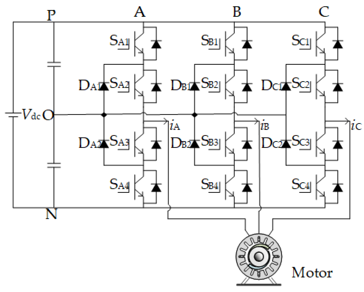
The topology of the NPC three-level inverter is shown in Figure 1, Vdc is the DC-link voltage, the upper and lower capacitors C1 and C2 are capacitors in parallel with the DC bus, each shares half of the DC bus voltage, and the values are defined as vC1 and vC2, respectively. The AC side is composed of three-phase bridge arms, representing A, B and C phases, each phase has two clamping diodes DX1~DX2 in series and four insulated gate bipolar transistor (IGBT) SX1~SX4 in series, iX is the three-phase load current, where X∈{A, B, C}.
According to the combination of turn-on and turn-off states of each phase power device, the three-level inverter can have different working states. When the power device is turned off, it is in parallel with the side capacitor. The voltage will be equal to the capacitor voltage, which is half of the DC bus voltage, the inverter can obtain P state or N state, and the value is not allowed to exceed the maximum rated voltage of the power device. The midpoint of the two power devices in the middle is connected to the load, generating phase current iX. The two clamping diodes are connected to the midpoint O, which can clamp the output of the inverter to the O state, so that the inverter can obtain three working states of P, O and N.
There are three switching states P, O and N for each phase of the NPC three-level inverter. Three different output phase voltages can be obtained by controlling the switching state of the power switches in each phase, as shown in Table 1. In the table, ‘1’ represents the turn-on state and ‘0’ represents the turn-off state.
2.1. Basic Principle of Synchronous Space Vector Modulation
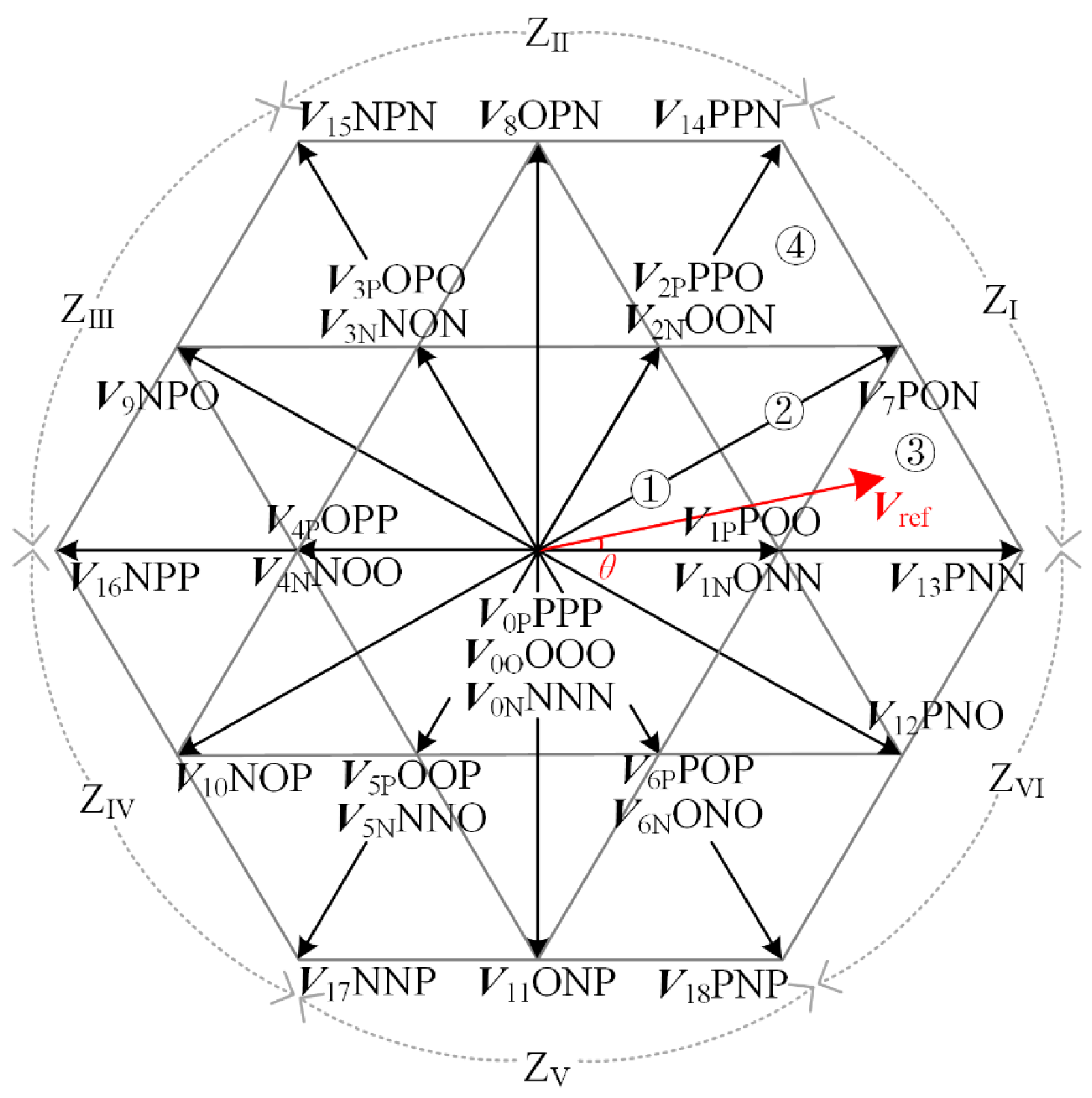
The three-phase arm of the inverter has 33 = 27 switching states corresponding to 27 basic voltage vectors. According to the magnitude, the basic voltage vectors can be divided into zero vectors (V0P, V0O, V0N), small vectors (V1P~V6P, V1N~V6N), medium vectors (V7~V12), large vectors (V13~V18). The space vector diagram can be divided into six sectors ZI~ZVI with the middle vector as the boundary. Connect the summits of the separated middle vectors sequentially, and each sector can further be divided into four triangles ①~④, Vref is the reference voltage vector, θ is the angle between reference voltage vector and α axis. The basic voltage vector and reference voltage vector corresponding to each switching state are shown in Figure 2.
The basic principle of SSVM is the same as that of asynchronous space vector modulation. The reference voltage vector is usually synthesized by three basic vectors closest to it. Each zero vector and small vector correspond to multiple switching states, which are called redundant switching states. According to the different optimization objectives, the appropriate redundant switching state is selected. For example, redundant vectors with small or zero common-mode voltage amplitude are selected to form a switching sequence, could achieve the effect of common mode voltage suppression or elimination; by adjusting the duty cycle of the redundant small vector switch state, the midpoint voltage balance is realized. According to the volt-second balance principle, the dwell times of the basic vectors can be obtained as follow:
In Equation (1), VX, VY and VZ represent the three basic vectors participating in the synthesis of the reference voltage vector Vref. TX, TY and TZ represent the action time of each basic voltage vector in a sub-cycle TS.
SSVM method is used to ensure the harmonic quality and low switching loss of the output waveform of the inverter in high voltage and high power applications. When designing the switching sequence, it is necessary to constrain the synchronization and symmetry of the output waveform of the inverter, and its switching frequency is limited.
Condition of synchronization and symmetry in term of switching states is shown in Table 2. In the table, is the complementary state of (P and N are complementary states, and the complementary state of O is still O). The synchronization constraint can keep the output phase voltage of the inverter strictly synchronized with the fundamental voltage. Three-phase symmetry is used to reduce the third harmonic content in the output phase voltage waveform of the inverter, and half-wave symmetry is used to reduce the even harmonic content in the output phase voltage waveform of the inverter.
2.2. Multi-Mode Synchronous Space Vector Modulation Method
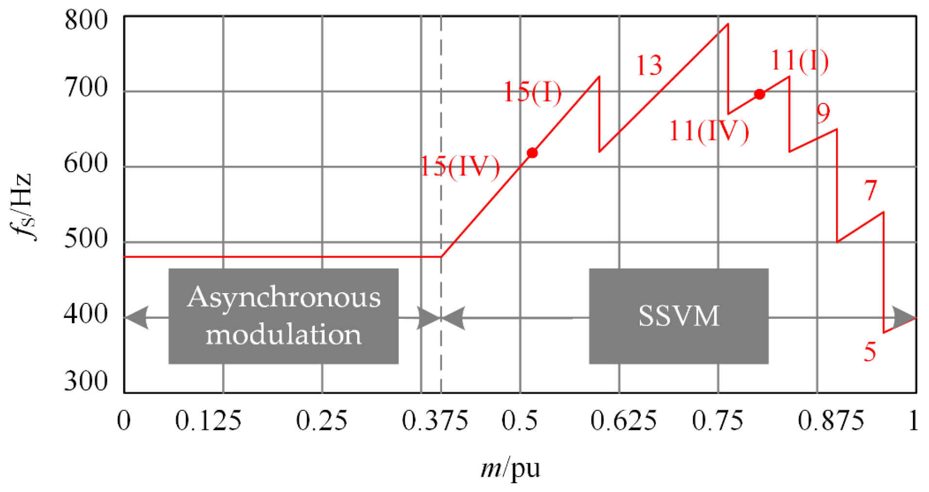
According to the above design principle of switching sequence, reference [22] gave the switching sequence with the lowest harmonic content of output waveform under different pulse number conditions, and inverter switching frequency can be limited over a wide output frequency range. This method divides the working range of the inverter into asynchronous space vector modulation interval and SSVM interval according to the modulation index m. When m ∈ [0, 0.4), the output frequency of the inverter is low, and the phase voltage can have a high number of pulses at low switching frequency. The asymmetric effect caused by asynchronous modulation is small, which avoids the frequent switching between different pulse numbers of SSVM and is simpler to implement. The control effect is excellent, so the asynchronous space vector modulation strategy is adopted; when m ∈ [0.4, 1), the output frequency of the inverter increases, the number of phase voltage pulses decreases, and enters the SSVM interval to ensure the three-phase symmetry. At the same time, the switching frequency should not exceed the allowable value of the selected power device. In the literature [22], the segmentation basis of different pulse numbers on the modulation index in the interval of SSVM has been analyzed and discussed in detail. The variation of pulse number with modulation index is shown in Figure 3, the brackets after pulse number indicate different clamping methods.
3. Stator Flux Trajectories of Synchronous Space Vector Modulation
The electromagnetic torque ripple can be reflected by the stator flux trajectories. If the flux trajectories appear to deviate, three phase currents of the inverter will oscillate.
3.1. The Change of Stator Flux Trajectories during Pulse Pattern Switching
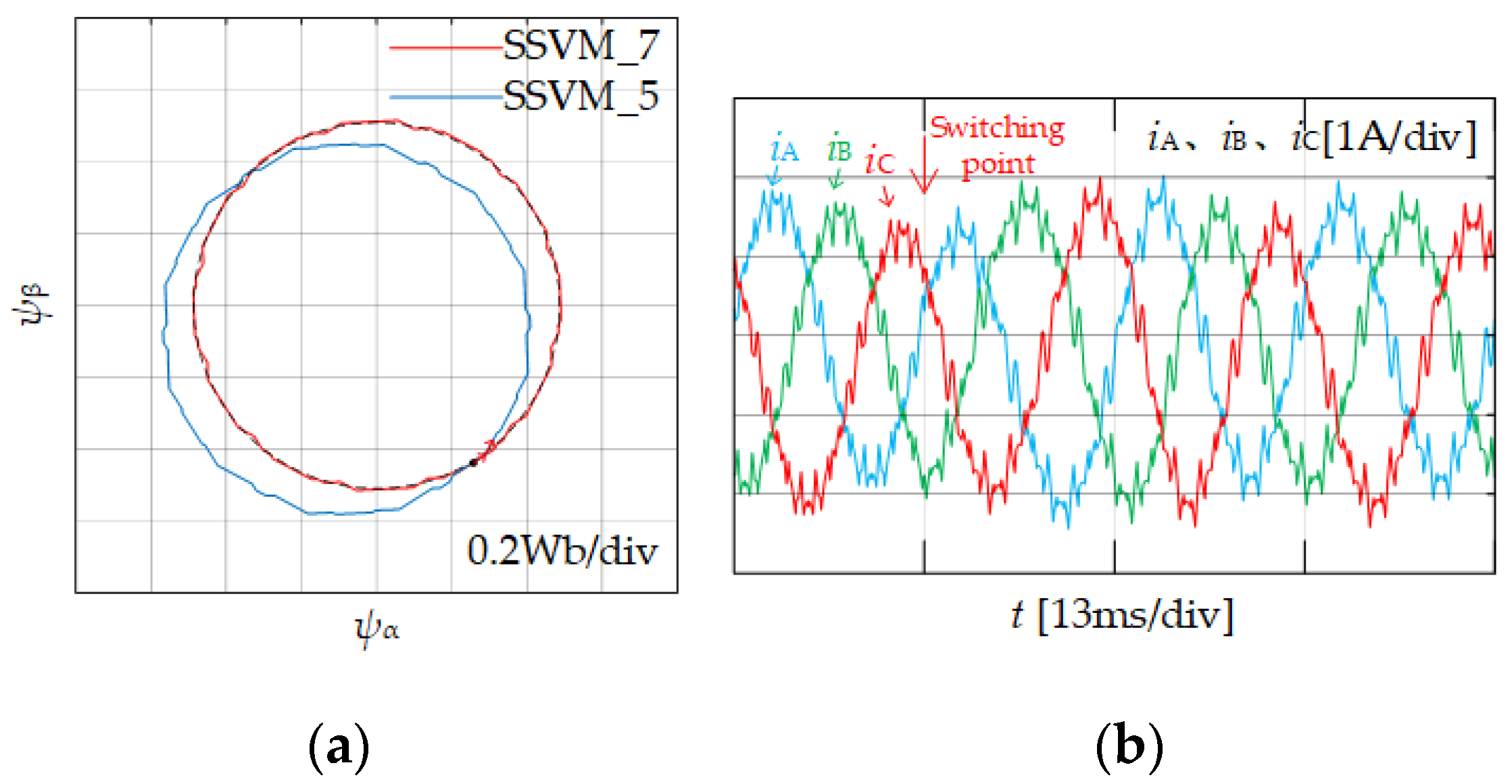
Pulse patterns of different pulse numbers should be switched under the same modulation index m. Ranges of the first reference voltage vector in each sector of different pulse number are the closest. In order to reduce the impact of the flux trajectories deviation, the pulse pattern switching should be carried out at the end of the sample period of the first reference voltage vector in each sector. The synchronous space vector modulation method under the pulse number P = 7 and P = 5 are named as SSVM_7 and SSVM_5.
According to the relationship between pulse number and modulation index of multi-mode SSVM method shown in Figure 3, the flux trajectories of switching from SSVM 7 to SSVM_5 at the end of the first reference voltage vector sub-cycle in ZI sector is shown in Figure 4a. Due to the difference of flux trajectories change rate of two pulse numbers, the flux trajectories of SSVM_5 will deviate from the flux trajectories of SSVM_7, and rotate along the new flux circle. The flux trajectories will deviate as shown in Figure 4b. Therefore, in order to eliminate the phenomenon of stator flux trajectories deviation after switching. It is necessary to compensate the phase angle of the reference voltage vector before switching, so that it changes along the original flux trajectories.
3.2. Stator Flux Trajectories Calculation
In order to eliminate the influence of stator flux trajectories deviation on the current, it is necessary to calculate the expression of the flux trajectories to correct the deviation during pulse pattern switching. When the motor operating frequency is not very low, the stator voltage drop can be ignored. At this time, the relationship between the stator flux vector ψS and the reference voltage vector Vref is shown in Equation (2):
In Equation (2), ω1 is the angular velocity of the motor during constant rotation, and θ is the angle between the reference voltage and the α axis, Equation (2) can be derived simultaneously on both sides:
It can be seen from Equation (3) that the reference voltage vector rotates with the same angular velocity ω1 as the stator flux trajectories, and Equation (3) is rewritten in incremental form:
In the Equation (4), ΔψS is the change rate of the flux trajectories, the reference voltage vector and the stator flux vector correspond to each other in the sub-cycle TS. When the motor works at a constant speed, it can be considered that the amplitude of the stator flux trajectories and the reference voltage is constant, so the flux trajectories’ deviation can be corrected by changing the phase angle of the reference voltage.
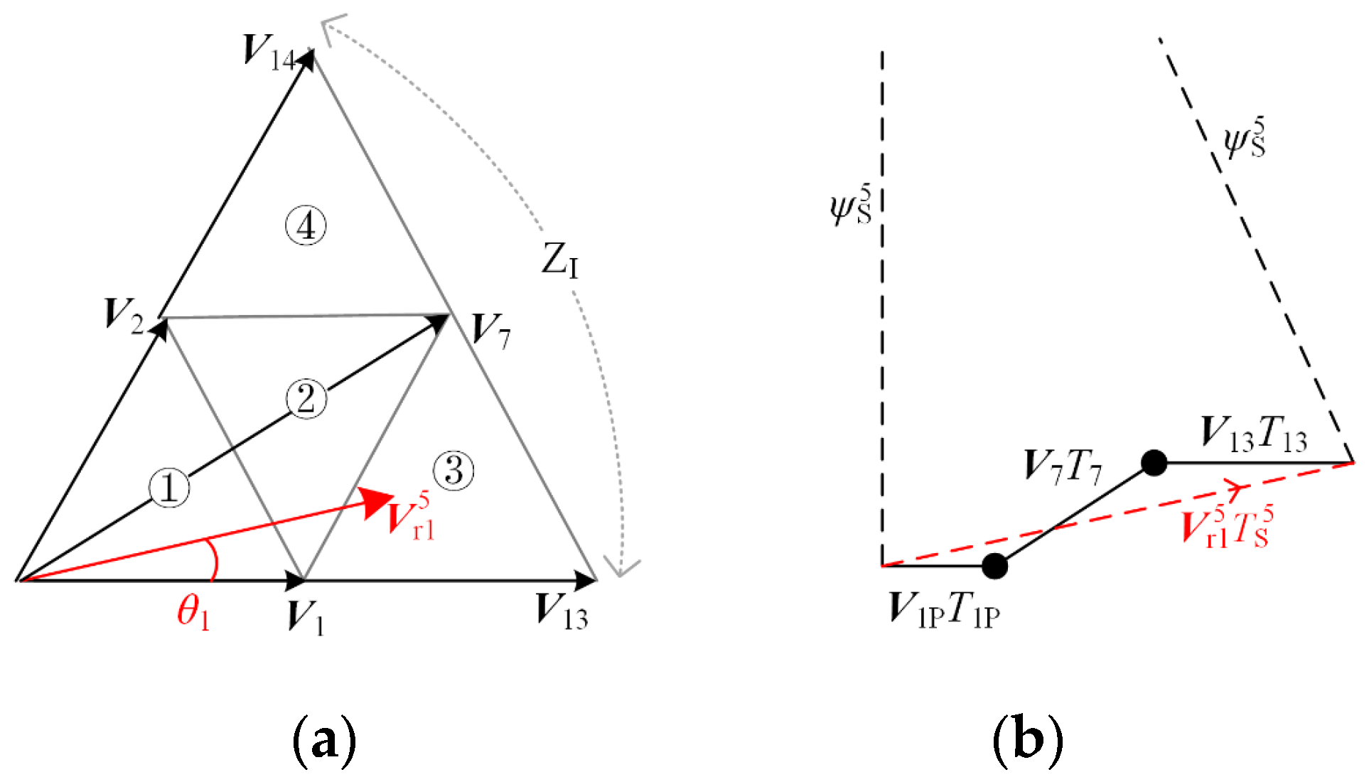
According to the space vector diagram shown in Figure 2, the change rate of flux trajectories of each reference voltage vector in TS can be obtained. Taking P = 5 as an example, the position of the reference voltage vector is shown in Figure 5a, = 1/30 fe, and rotates 12° per sub-cycle. The switching sequence used to synthesize is: V1P→V7→V13, and the flux trajectories of is shown in Figure 5b. In the figure, the black solid line is the actual flux trajectories change, and the red dotted line is the equivalent flux trajectories change rate.
4. Smooth Switching Method
In order to eliminate the influence of flux trajectories deviation, a method of directly compensating the phase angle of reference voltage is adopted, changing the flux trajectories change rate to achieve switching between different pulse numbers.
4.1. Switch between Asynchronous Modulation and SSVM_15 (IV)
When switching between asynchronous space vector modulation and SSVM_15(IV), because the switching frequency of the two modulation methods does not abrupt change during switching, it is relatively easy to implement. Therefore, in the case of ensuring that the output frequency and modulation index of the inverter before and after switching do not change abruptly, the influence of the reference voltage vector compensation angle is not considered. Just ensure that the reference voltage phase angle is not intermittent when switching between the two modulation methods. When the asynchronous space vector modulation is switched to SSVM_15(IV), according to Figure 3, the modulation index m = 0.4, in order to ensure the continuity of the stator flux trajectories during switching, and the switching can be performed at the phase angle where the reference voltage vector, which begins in each sub-cycle of the SSVM_15(IV).
4.2. Switching between Different Clamping Methods of SSVM
The modulation method with the same number of pulses and different clamping methods, its smooth switching strategy also needs to be analyzed. According to the multi-mode SSVM method shown in Figure 3, there will be switching between different clamping modes when the number of pulses is P = 15 and the number of pulses is P = 11. Since the switching frequency does not change abruptly before and after switching, and the number and distribution of reference voltage vectors are the same in the fundamental period, only the switching sequences of synthesized reference voltage vectors are different. Under the condition that the fundamental frequency and modulation index do not change before and after switching, flux trajectories change rate is the same, and the same flux circle is before and after switching, and the current will not impulse oscillation. Therefore, the same as the switching between asynchronous modulation and synchronous modulation, it can be performed at the phase angle where the reference voltage vector begins in each sub-cycle of the modulation method.
4.3. Switching between Different Pulse Numbers of SSVM
According to the analysis in Section 3.1, when switching between different pulse numbers, it will cause abrupt change of switching frequency and the flux trajectories deviation. The current impulse oscillation will be very serious. Taking the switching from SSVM_7 to SSVM_5 as an example, the modulation index m = 0.96 and the amplitude of stator flux trajectories is constant. In SSVM_7, = 1/36fe, rotates 10° per sub-cycle. The flux trajectories change rates of the two pulse numbers under the action of the first reference voltage vector in the ZI sector are shown in Figure 6.
According to the flux trajectories of SSVM_7 and SSVM_5 shown in Figure 6, the stator flux vector of SSVM_7 rotates 10° in each sub-cycle, and the reference voltage phase angle changes from 5° to 15°. The stator flux vector of SSVM_5 rotates 12° in each sub-cycle, and the reference voltage phase angle changes from 6° to 18°. Due to the different flux trajectories change rate, the angle of flux vector rotation is different at the end of the reference voltage vector action, resulting in angle deviation, such as the shadow part in the Figure 6. If the two modulation methods are switched directly, due to the angle of deviation of the shadow part in the figure, it will cause the flux trajectories to deviate. Therefore, the reference voltage phase angle needs to be compensated, in order to make the flux trajectories change rate the same during switching.
SSVM_7 has 36 reference voltage vectors in each fundamental period, so the frequency of each sub-period is 36 fe. According to Equation (4), SSVM_7 flux trajectories change rate Δ is:
Since the magnitude of the flux vector is approximately equal in each sub-cycle, it can form an isosceles triangle with Δ, according to sine theorem, the flux vector amplitude of SSVM_7 can be expressed as:
Similarly, the flux vector amplitude of SSVM_5 is:
At this time, when SSVM_7 switching to SSVM_5, the expression of complex compensation gain k7_5 is:
In Equation (8), = ej5°, ej282° and ej270° indicate that the stator flux vector ψs rotates from 270° to 282°. The complex compensation gain k7_5 = ej0.85° can be obtained by substituting Equations (6) and (7) into Equation (8), since the value of the complex compensation gain k is a constant independent of any parameter, its value can be calculated offline.
In summary, the reference voltage phase angle of SSVM_7 is compensated by 0.85° using complex compensation method and then switching, the compensated reference voltage vector phase angle is 60°·n − 55° (n = 1, 2, …, 6), so there are six switching points in each fundamental cycle.
Similarly, when SSVM_5 switches to SSVM_7, the value of complex compensation gain k5_7 can be calculated:
In the Equation (9), = ej6°, complex compensation gain k5_7 = ej−0.82°. Therefore, the reference voltage phase angle of SSVM_5 should be compensated by −0.82° and then switching, and the compensated reference voltage vector phase angle is 60°·n − 54°.
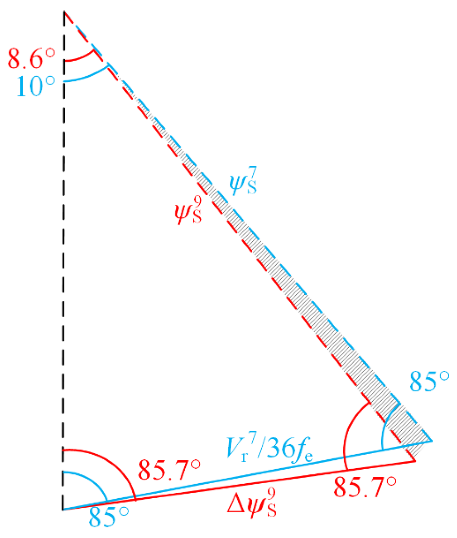
When SSVM_9 is switching to SSVM_7, modulation index m = 0.9. In SSVM_9, = 1/42 fe, rotates 8.57° per sub-cycle. The flux trajectories change rates of the two pulse numbers under the action of the first reference voltage vector in the ZI sector are shown in Figure 7.
Similar to the above method for obtaining the complex compensation gain, the flux vector amplitude of SSVM_9 can be expressed as:
At this time, when SSVM_9 switching to SSVM_7, the expression of complex compensation gain k9_7 is:
In the Equation (11), = ej4.3°, complex compensation gain k9_7 = ej−0.6°. Therefore, the reference voltage phase angle of SSVM_9 should be compensated by −0.6° and then switching, and the compensated reference voltage vector phase angle is 60°·n − 55.7°.
Similarly, when SSVM_7 switches to SSVM_9, the value of complex compensation gain k7_9 can be calculated:
In Equation (12), = ej5°, complex compensation gain k7_9 = ej0.69°. Therefore, the reference voltage phase angle of SSVM_9 should be compensated by 0.69° and then switched, and the compensated reference voltage vector phase angle is 60°·n − 55°.
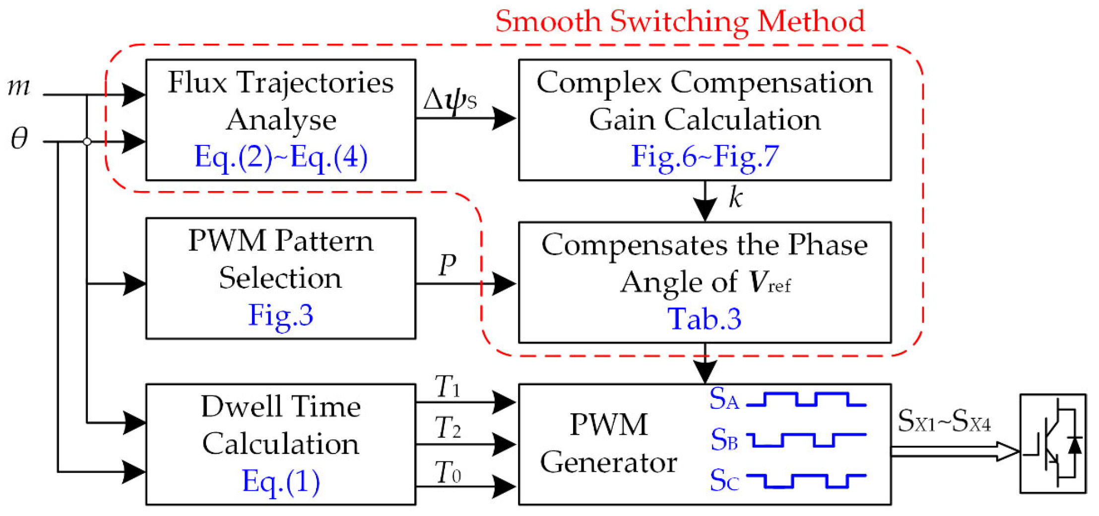
The calculation method of complex compensation gain k for switching between other pulse numbers in multi-mode SSVM method is the same as the above process. Due to space limitations, the calculation process is not listed step by step, the calculation results are shown only in Table 3, and the flow block diagram of the smooth switching method is shown in Figure 8. According to Figure 8, the proposed smooth switching strategy first needs to calculate the flux trajectories before and after switching according to Equations (2)–(4); Then, draw flux trajectories change rate, such as Figure 6 and Figure 7, and the value of k is calculated; Finally, according to the value of k in Table 3, the reference voltage vector phase angle is compensated.
5. Experimental Result
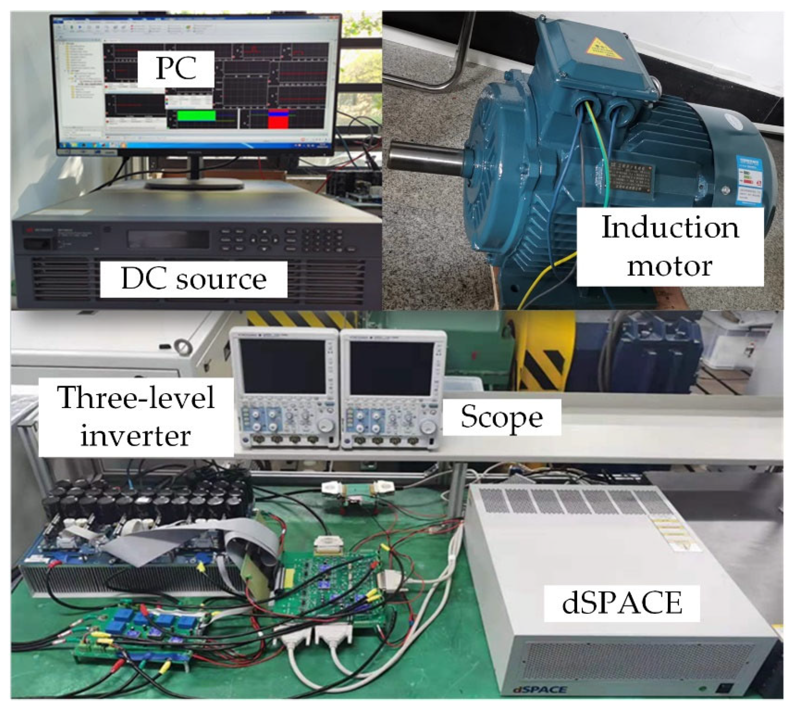
In order to verify the effectiveness of the proposed smooth switching method, and build a rapid prototyping experimental system based on dSPACE three-level inverter. The dSPACE® DS1007 rapid prototyping experimental system is used as the controller, the Infineon® IGBT module F3L75R07W2E3 is used as the power circuit. The experimental system also includes DC power supply, voltage/current sensor, PC and signal conversion circuit. Then, the experimental verification is carried out in a 7.5 kW induction motor. In order to clearly prove that the smooth switching of the motor can be achieved by using only the modulation strategy, the asynchronous motor is directly powered by an open-loop NPC inverter, and the sampling frequency of the dSPACE board is set to 50 kHz. A comparative analysis was conducted, about the phase angle of the reference voltage vector is not compensated and compensated when switching different pulse numbers. The experimental system and experimental parameters are shown in Table 4 and Figure 9.
5.1. Switching Experiment of Asynchronous Modulation and Synchronous Modulation
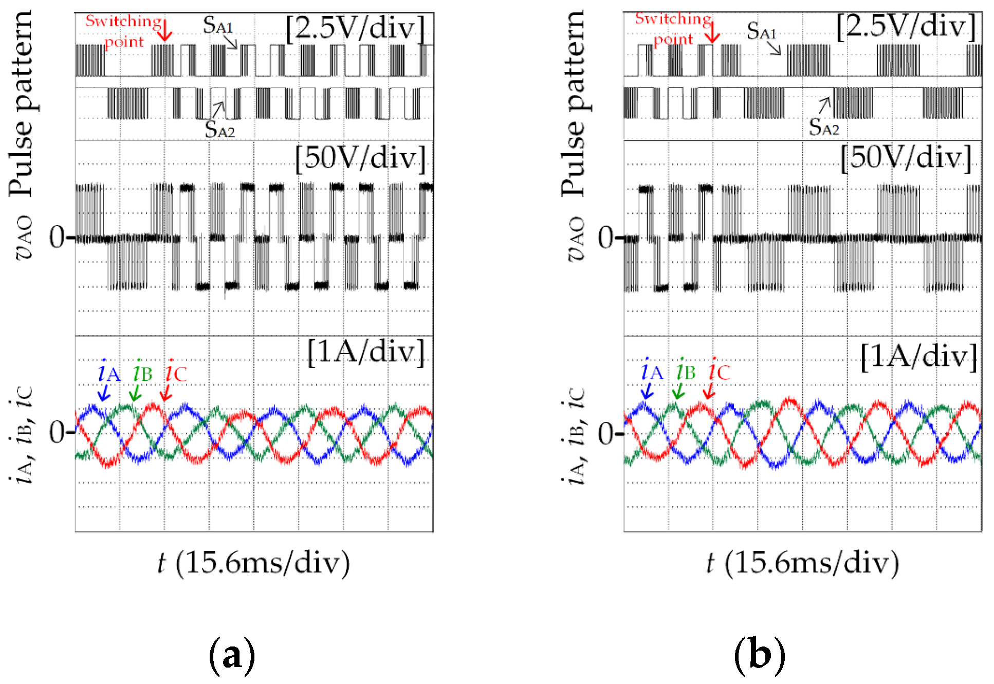
Figure 10 shows the experimental results of motor switching between asynchronous space vector modulation and SSVM_15 (IV) when m = 0.4, reference voltage vector phase angle of 2.3°. From top to bottom is the pulse pattern of power devices SA1 and SA2, phase voltage vAO, three-phase current iA, iB, iC. Since there is no deviation in the stator flux trajectories during switching, the three-phase current has no impulse oscillation, achieving smooth switching.
5.2. Switching Experiment of Different Clamping Methods of SSVM
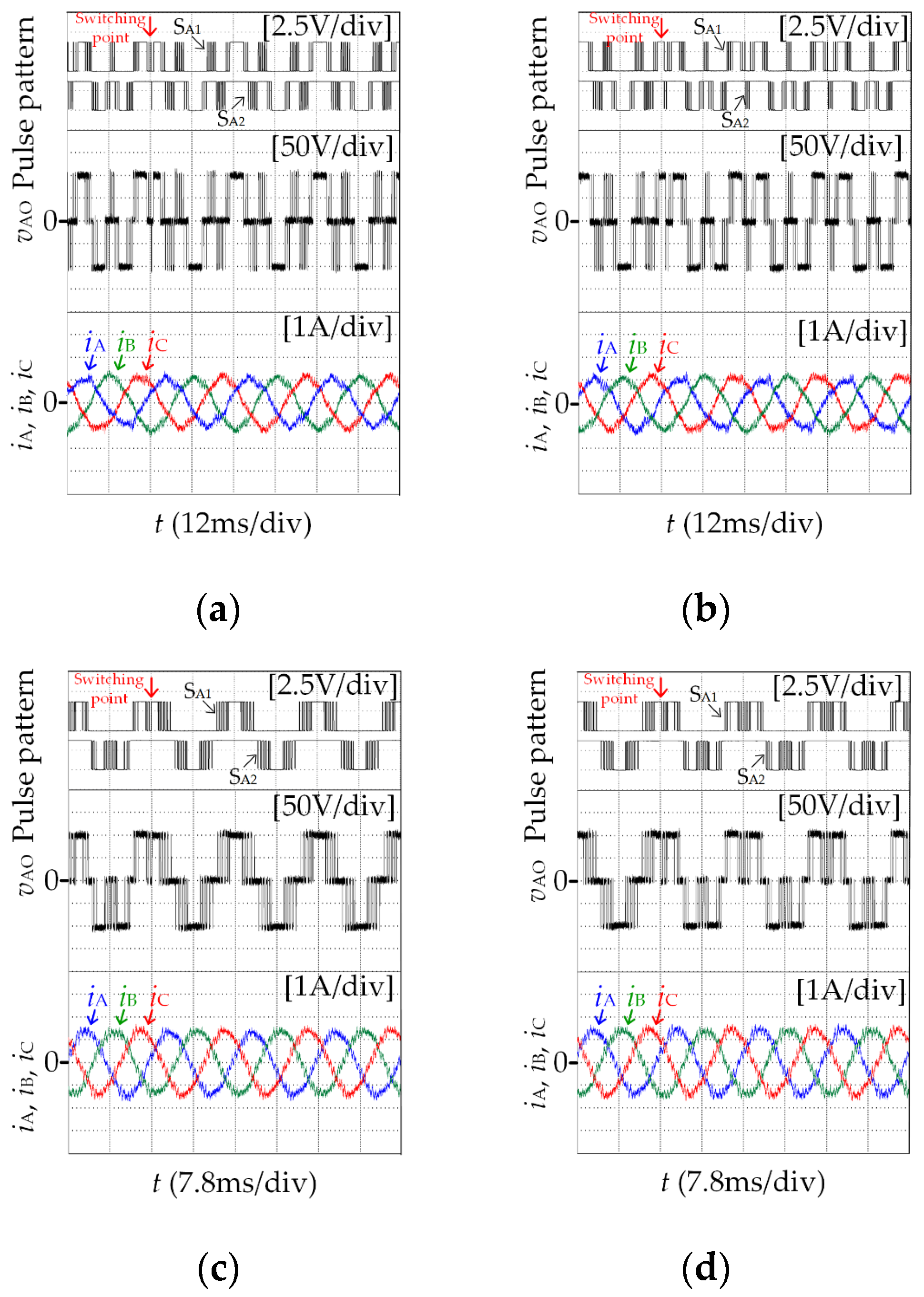
Figure 11a,b shows the experimental results of motor switching in different clamping methods at P = 15 when m = 0.52, reference voltage vector phase angle of 2.3°. Figure 11c,d shows the experimental results of motor switching in different clamping methods at P = 11 when m = 0.8, reference voltage vector phase angle of 3.5°. Since there is no deviation in the stator flux trajectories during switching, the three-phase current has no impulse oscillation, achieving smooth switching.
5.3. Switching Experiment of Different Pulse Numbers of SSVM
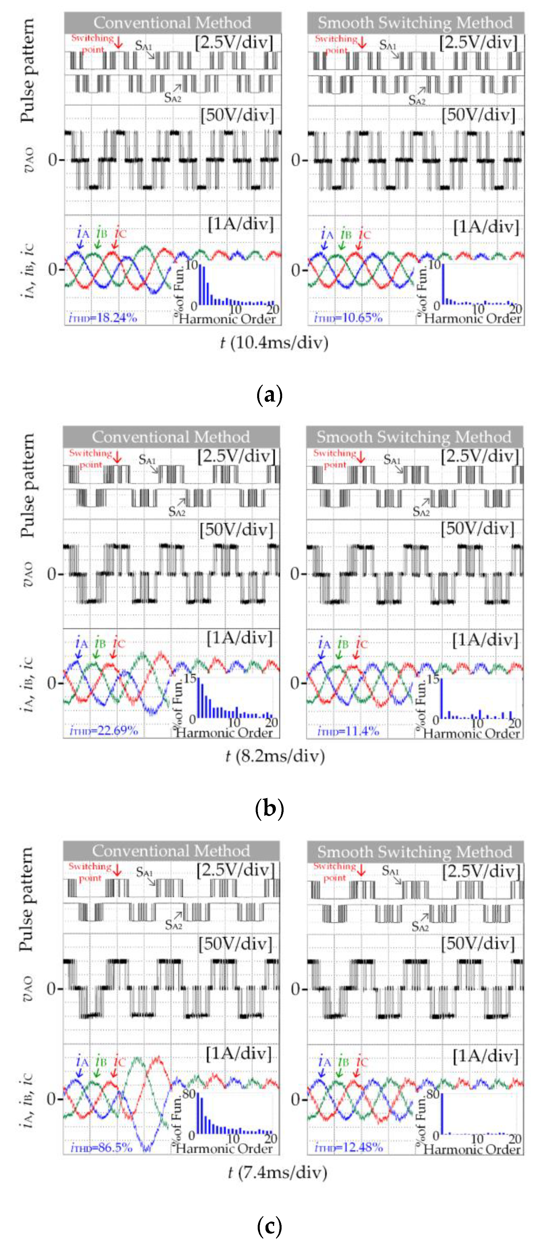
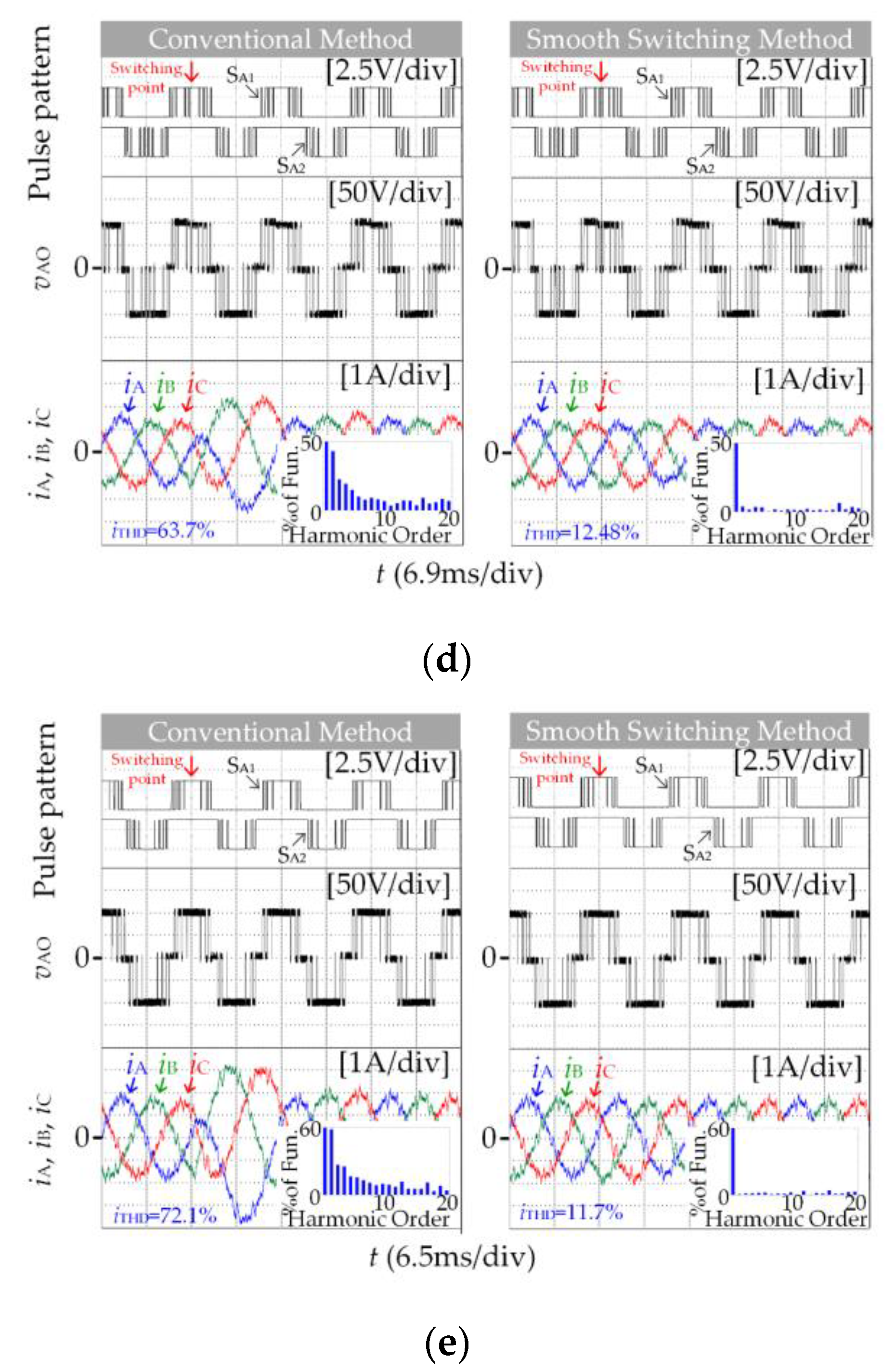
The top experimental diagram in Figure 12 is the pulse pattern of the power devices SA1 and SA2, and the position of the switching point can be seen through the waveform when the motor frequency rises in the multi-mode SSVM method. When switching between different pulse numbers, the three-phase current waveform will produce impulse oscillation due to flux trajectories deviation. As the number of pulses decreases during switching, the impact oscillation becomes more and more obvious, as shown in the left experimental results. After using complex compensation gain to compensate the reference voltage vector phase angle before switching, flux trajectories deviation was corrected. From the right experimental results, the three-phase current does not appear impulse oscillation, and smooth switching is achieved. Similarly, the fundamental frequency of the motor decreases, the three-phase current will not also impulse oscillation.
The motor model in the experiment is a non-ideal model that is affected by environmental factors such as temperature and noise. Its parameters such as inductance and resistance will also be inconsistent with the theoretical value due to manufacturing errors. The motor model in the simulation is an ideal model that is not affected by any factors. Comparing the simulation results Figure 4b and the experimental results Figure 12e when SSVM_7 switches to SSVM_5, it can be seen that, during the experiment, the motor is affected by many external factors, and the current impulse oscillation is more serious when the switch is directly switching. Therefore, the necessity of adding a smooth switching strategy to the modulation method in industrial applications is more clearly demonstrated.
Using current total harmonic distortion rate iTHD as the quality evaluation standard of inverter output waveform, analyze the A-phase output current iA during switching. It can be seen from the current harmonic content in Figure 12, after the smooth switching method is adopted, the harmonic content and total harmonic distortion rate in the current are significantly reduced. Among them, the amplitude of low-order harmonics mainly by second and fourth harmonics decreases obviously, and more than ten times higher harmonic amplitude has also been reduced, resulting in the inverter having better output waveform quality.
5.4. Output Waveform Quality
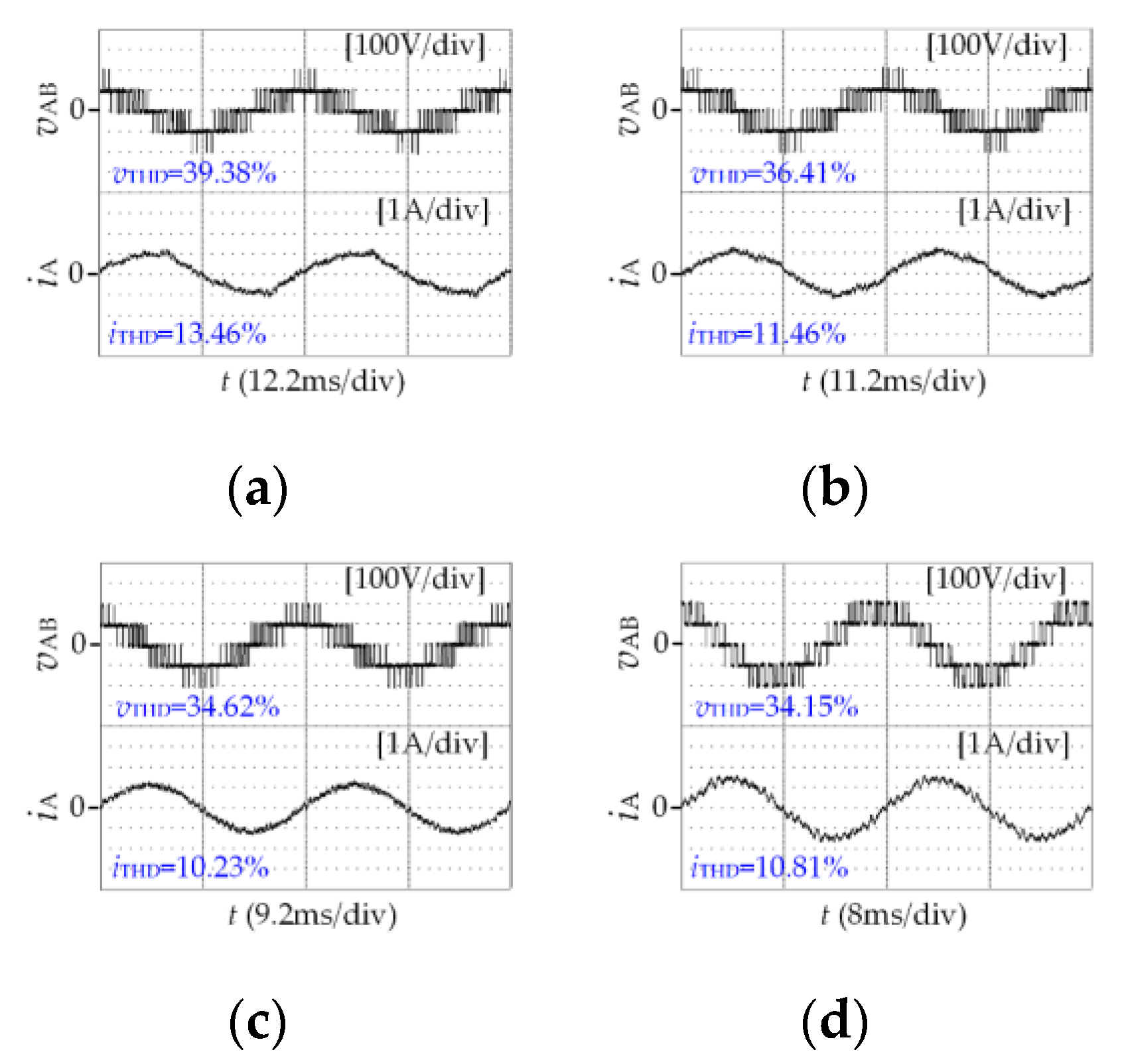
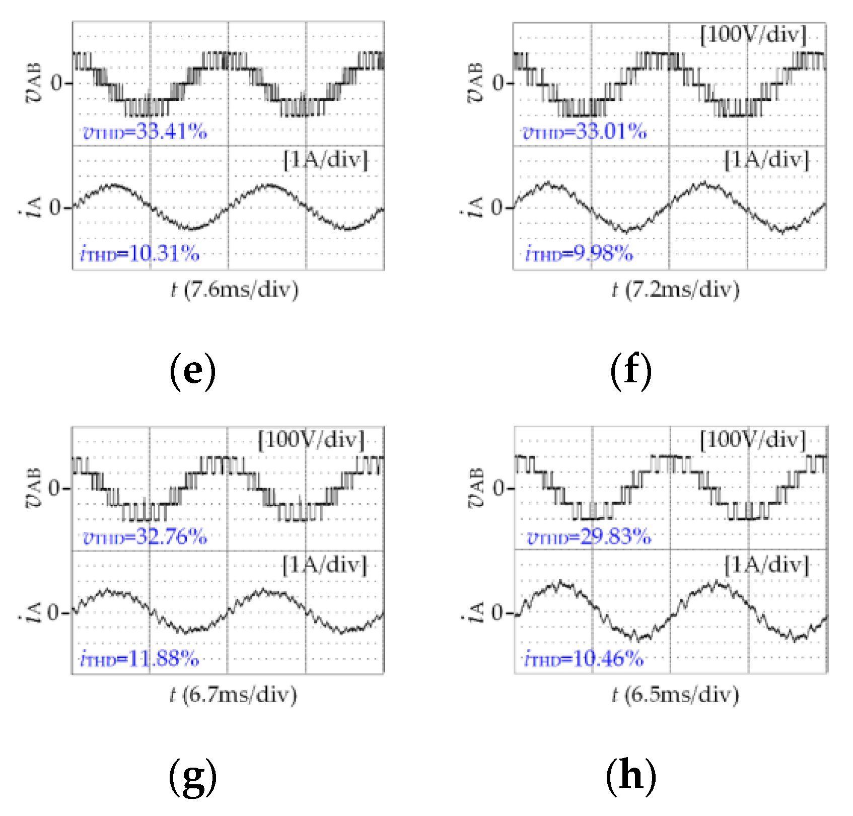
The line voltage total harmonic distortion vTHD and A-phase current total harmonic distortion iTHD of the multi-mode SSVM with different pulse numbers are shown in Figure 13. It can be seen that due to the symmetry and synchronization of synchronous space vector modulation, the vTHD and iTHD are reduced at a lower switching frequency. As the number of pulses decreases after the fundamental frequency increases, vTHD and iTHD do not increase significantly.
When the modulation strategy is the same, the fundamental voltage amplitude will increase as the modulation index increases, the voltage utilization rate will also be increased, and the voltage waveform is closer to the sine wave. At this time, the total harmonic distortion THD obtained by Fourier transform will also be reduced.
6. Conclusions
This paper proposes a smooth switching method based on continuous stator flux trajectories for three-level inverter, the problem of current impulse oscillation is solved when the different pulse numbers is switching in the multi-mode SSVM method. Firstly, the reason for the impact oscillation of the three-phase current during the switching of different modulation methods is analyzed, which is caused by deviations in the stator flux trajectories. Then by constructing flux vector triangle, the complex compensation gain k which can correct the flux trajectories deviation is calculated by using geometric relationship, and the phase angle of reference voltage vector is compensated by complex gain. Finally, the proposed method is verified on induction motor, and compared with the traditional switching method. The experimental results are consistent with the theoretical analysis, which proves the feasibility and effectiveness of the proposed smooth switching method. However, the proposed smooth switching strategy can only be performed at several switching points in each fundamental period, and cannot be switched at any position in the fundamental period, which will be the focus of further research in the future.
Author Contributions
Conceptualization, G.Z. (Guozheng Zhang) and X.G.; methodology, G.Z. (Guozheng Zhang) and G.Z. (Guoao Zhao); software, G.Z. (Guoao Zhao); validation, G.Z. (Guozheng Zhang) and X.L.; formal analysis, G.Z. (Guozheng Zhang) and C.L.; writing—original draft preparation, G.Z. (Guoao Zhao); writing—review and editing, X.G. and G.Z. (Guozheng Zhang); funding acquisition, X.G. and X.L. All authors have read and agreed to the published version of the manuscript.
Funding
This research was funded by The National Natural Science Foundation of China, grant number 52177055, The Zhejiang Provincial Basic Public Welfare Research Projects, grant number LGG22E070010.
Data Availability Statement
Not applicable.
Conflicts of Interest
The authors declare no conflict of interest.
Abbreviations
The main abbreviations used are as follows, the abbreviation with superscript appears in the paper as its value under the corresponding pulse number.
| Switching frequency | fs |
| Output fundamental frequency | fe |
| Pulse number | P |
| Complex compensation gain | k |
| Phase current | iX, X∈{A, B, C}. |
| Reference voltage vector | Vref |
| reference voltage vector phase angle | θ |
| Sub-cycle times | TS |
| Modulation index | m |
| Stator flux vector | ψS |
| Stator flux trajectories change rate | ΔψS |
| Voltage total harmonic distortion | vTHD |
| Current total harmonic distortion | iTHD |
References
- Zhang, G.; Su, Y.; Zhou, Z.; Geng, Q. A Carrier-Based Discontinuous PWM Strategy of NPC Three-Level Inverter for Common-Mode Voltage and Switching Loss Reduction. Electronics 2021, 10, 3041. [Google Scholar] [CrossRef]
- Ouanjli, N.E.; Derouich, A.; Ghzizal, A.E.; Taoussi, M.; Bossoufi, B. Direct Torque Control of Doubly Fed Induction Motor Using Three-Level NPC Inverter. Prot. Control Mod. Power Syst. 2019, 4, 17. [Google Scholar] [CrossRef] [Green Version]
- Saady, I.; Karim, M.; Bossoufi, B.; Ouanjli, N.E.; Motahhir, S.; Majout, B. Optimization and Control of Photovoltaic Water Pumping System Using Kalman Filter Based MPPT and Multilevel Inverter Fed DTC-IM. Results Eng. 2023, 17, 100829. [Google Scholar] [CrossRef]
- Alawieh, H.; Tehrani, K.A.; Azzouz, Y.; Dakyo, B. A New Active Common-Mode Voltage Elimination Method for Three-Level Neutral-Point Clamped Inverters. In Proceedings of the Conference of the IEEE Industrial Electronics Society (IECON), Dallas, TX, USA, 29 October–1 November 2014; pp. 1060–1066. [Google Scholar]
- Ma, Z.; Niu, H.; Wu, X.; Zhang, X.; Lin, G. An Improved Overmodulation Strategy for a Three-Level NPC Inverter Considering Neutral-Point Voltage Balance and Common-Mode Voltage Suppression. Sustainability 2022, 14, 12558. [Google Scholar] [CrossRef]
- Ahmadi, S.; Poure, P.; Khaburi, D.A.; Saadate, S. A Remedial Control for Short-Circuit Fault in NPC/H-Bridge Inverters without Redundant Component. Electronics 2021, 10, 2411. [Google Scholar] [CrossRef]
- Tehrani, K.A.; Bendjedia, M.; Azzouz, Y. Design of RST and Fractional Order PID Controllers for an Induction Motor Drive for Electric Vehicle Application. In Proceedings of the IET International Conference on Power Electronics, Manchester, UK, 8–10 April 2014. [Google Scholar]
- Szular, Z.; Rozegnal, B.; Mazgaj, W.A. New Soft-Switching Solution in Three-Level Neutral-Point-Clamped Voltage Source Inverters. Energies 2021, 14, 2247. [Google Scholar] [CrossRef]
- Rathore, R.; Holtz, J.; Boller, T. Generalized Optimal Pulsewidth Modulation of Multilevel Inverters for Low-Switching-Frequency Control of Medium-Voltage High-Power Industrial AC Drives. IEEE Trans. Ind. Appl. 2013, 60, 4215–4224. [Google Scholar] [CrossRef]
- Zhang, G.; Peng, S.; Geng, Q.; Shi, T.; Xia, C. Hybrid Discontinuous Space Vector PWM Strategy for Three-Level Inverters Under Two-Phase Loads Condition. IEEE Trans. Power Electron. 2021, 37, 1711–1721. [Google Scholar] [CrossRef]
- Gao, Z.; Ge, Q.; Li, Y.; Zhao, L.; Zhang, B.; Wang, K. Hybrid Improved Carrier-Based PWM Strategy for Three-Level Neutral-Point-Clamped Inverter With Wide Frequency Range. IEEE Trans. Power Electron. 2021, 36, 8517–8538. [Google Scholar] [CrossRef]
- Fei, W.; Du, X.; Wu, B. A Generalized Half-Wave Symmetry SHE-PWM Formulation for Multilevel Voltage Inverters. IEEE Trans. Ind. Electron. 2010, 57, 3030–3038. [Google Scholar]
- Memon, M.A.; Mekhilef, S.; Mubin, M.; Aamir, M. Selective Harmonic Elimination in Inverters Using Bio-Inspired Intelligent Algorithms for Renewable Energy Conversion Applications: A Review. Renew. Sustain. Energy Rev. 2018, 82, 2235–2253. [Google Scholar] [CrossRef]
- Zhang, Z.; Ge, X.; Tian, Z.; Zhang, X.; Tang, Q.; Fang, X. A PWM for Minimum Current Harmonic Distortion in Metro Traction PMSM With Saliency Ratio and Load Angle Constrains. IEEE Trans. Power Electron. 2018, 33, 4498–4511. [Google Scholar] [CrossRef]
- He, K.; Li, J.; Xiao, L.; Xiong, Y.; Wu, L. Randomized Pulse Pattern Strategy of Synchronized SVPWM for Low-Frequency-Ratio Applications. IEEE Trans. Power Electron. 2021, 36, 6404–6414. [Google Scholar] [CrossRef]
- Zhang, G.; Wei, B.; Gu, X.; Li, M.; Zhou, Z.; Chen, W. Sector Subdivision Based SVPWM Strategy of Neutral-Point-Clamped Three-Level Inverter for Current Ripple Reduction. Energies 2019, 12, 2734. [Google Scholar] [CrossRef] [Green Version]
- Mo, X.; Huang, K.; Fan, H.; Wu, H.; Chen, L. Segmented Multi-mode Modulation Algorithm Based on Synchronized SVPWM for Rail Transit Traction Motor. In Proceedings of the International Conference on Electrical Machines and Systems (ICEMS), Harbin, China, 11–14 August 2019; pp. 1–4. [Google Scholar]
- Zhou, M.; Liu, W.; Qiu, T.; Wang, C.; You, X. A Genaral Switching Strategy for Multi-Mode Pulse Width Modulation. Proc. CSEE 2019, 39, 2125–2132. [Google Scholar]
- Chu, Y.; Zhou, M.; Dong, S.; Wang, C.; Wang, B. A General Switching Strategy of Multimode Modulation Based on Flux Deviation Vector. Proc. CSEE 2022, 42, 4162–4170. [Google Scholar]
- Wang, C.; Wang, K.; You, X. Research on Synchronized SVPWM Strategies Under Low Switching Frequency for Six-Phase VSI-Fed Asymmetrical Dual Stator Induction Machine. IEEE Trans. Power Electron. 2016, 63, 6767–6776. [Google Scholar] [CrossRef]
- Wang, K.; You, X.; Wang, C.; Zhou, M. Research on Synchronized SVPWM Strategies Under Low Switching Frequency. Proc. CSEE 2015, 35, 4175–4183. [Google Scholar]
- Zhang, G.; Zhou, Z.; Shi, T.; Xia, C. An Improved Multimode Synchronized Space Vector Modulation Strategy for High-Power Medium-Voltage Three-Level Inverter. IEEE Trans. Power Electron. 2020, 36, 4686–4696. [Google Scholar] [CrossRef]
Figure 1.
The topology of neutral-point-clamped three-level inverter.

Figure 2.
The space vector diagram of three-level inverter.

Figure 3.
The variation of pulse number with the change of modulation index.

Figure 4.
Stator flux trajectories and current change during switching. (a) Stator flux trajectories change. (b) Current change.
Figure 4.
Stator flux trajectories and current change during switching. (a) Stator flux trajectories change. (b) Current change.

Figure 5.
Relationship between space vector and flux trajectories. (a) in sectors ZI. (b) Flux trajectories change in subcycle.
Figure 5.
Relationship between space vector and flux trajectories. (a) in sectors ZI. (b) Flux trajectories change in subcycle.

Figure 6.
Flux trajectories Change rate of SSVM_7 and SSVM_5.

Figure 7.
Flux trajectories Change rate of SSVM_9 and SSVM_7.

Figure 8.
The flow block diagram of the smooth switching method.

Figure 9.
The prototype of dSPACE® DS1007 driven three-level inverter.

Figure 10.
Experimental results of asynchronous modulation and SSVM_15(IV) switching. (a) Asynchronous modulation→SSVM_15 (IV). (b) SSVM_15 (IV)→asynchronous modulation.
Figure 10.
Experimental results of asynchronous modulation and SSVM_15(IV) switching. (a) Asynchronous modulation→SSVM_15 (IV). (b) SSVM_15 (IV)→asynchronous modulation.

Figure 11.
Experimental results of different clamping method switching of SSVM. (a) SVM_15(IV)→SSVM_15(I). (b) SSVM_15(I)→SSVM_15(IV). (c) SVM_11(IV)→SSVM_11(I). (d) SSVM_11(I)→SSVM_11(IV).
Figure 11.
Experimental results of different clamping method switching of SSVM. (a) SVM_15(IV)→SSVM_15(I). (b) SSVM_15(I)→SSVM_15(IV). (c) SVM_11(IV)→SSVM_11(I). (d) SSVM_11(I)→SSVM_11(IV).

Figure 12.
Experimental results of different pulse numbers switching. (a) m = 0.6, SSVM_15(I)→SSVM_13. (b) m = 0.76, SSVM_13→SSVM_11(IV). (c) m = 0.84, SSVM_11(I)→SSVM_9. (d) m = 0.9, SSVM_9→SSVM_7. (e) m = 0.96, SSVM_7→SSVM_5.
Figure 12.
Experimental results of different pulse numbers switching. (a) m = 0.6, SSVM_15(I)→SSVM_13. (b) m = 0.76, SSVM_13→SSVM_11(IV). (c) m = 0.84, SSVM_11(I)→SSVM_9. (d) m = 0.9, SSVM_9→SSVM_7. (e) m = 0.96, SSVM_7→SSVM_5.


Figure 13.
Experimental results of vTHD and iTHD. (a) m = 0.51, P = 15(IV). (b) m = 0.56, P = 15(I). (c) m = 0.68, P = 13. (d) m = 0.78, P = 11(IV). (e) m = 0.82, P = 11(I). (f) m = 0.86, P = 9. (g) m = 0.93, P = 7. (h) m = 0.96, P = 5.
Figure 13.
Experimental results of vTHD and iTHD. (a) m = 0.51, P = 15(IV). (b) m = 0.56, P = 15(I). (c) m = 0.68, P = 13. (d) m = 0.78, P = 11(IV). (e) m = 0.82, P = 11(I). (f) m = 0.86, P = 9. (g) m = 0.93, P = 7. (h) m = 0.96, P = 5.


Table 1.
The definition of switching state for three phases.
| Power Device | Switch Status | Phase Voltage | |||
|---|---|---|---|---|---|
| SX1 | SX2 | SX3 | SX4 | ||
| 1 | 1 | 0 | 0 | P | Vdc/2 |
| 0 | 1 | 1 | 0 | O | 0 |
| 0 | 0 | 1 | 1 | N | −Vdc/2 |
Table 2.
Condition of synchronization and symmetry in term of switching states.
| Synchronization | Three-Phase Symmetry | Half-Wave Symmetry | ||
|---|---|---|---|---|
| θ | θ ± 2π | θ + 2/3π | θ − 2/3π | θ ± π |
| Sa | Sa | Sc | Sb | |
| Sb | Sb | Sa | Sc | |
| Sc | Sc | Sb | Sa | |
* denotes the complementary state of the corresponding switching state.
Table 3.
Complex compensation gain k calculation results.
| Pulse Number Change during Switching | Complex Compensation Gain k | The Compensated Vref Phase Angle |
|---|---|---|
| SSVM_15→SSVM_13 | k15_13 = ej−2.06° | 60°·n − 57.7° |
| SSVM_13→SSVM_11 | k13_11 = ej3.14° | 60°·n − 57.5° |
| SSVM_11→SSVM_9 | k11_9 = ej0.03° | 60°·n − 56.5° |
| SSVM_9→SSVM_7 | k9_7 = ej−0.6° | 60°·n − 55.6° |
| SSVM_7→SSVM_5 | k7_5 = ej0.85° | 60°·n − 55° |
| SSVM_5→SSVM_7 | k5_7 = ej−0.82° | 60°·n − 54° |
| SSVM_7→SSVM_9 | k7_9 = ej0.69° | 60°·n − 55° |
| SSVM_9→SSVM_11 | k9_11 = ej−0.06° | 60°·n − 55.6° |
| SSVM_11→SSVM_13 | k11_13 = ej−4.1° | 60°·n − 56.5° |
| SSVM_13→SSVM_15 | k13_15 = ej2.27° | 60°·n − 57.5° |
Table 4.
Experimental parameters.
| Parameters | Values |
|---|---|
| DC-link voltage Vdc/V | 200 |
| Rated power P/kW | 7.5 |
| Rated frequency fN/Hz | 50 |
| Rated current IN/A | 17.8 |
| Rated speed nN/(r/min) | 720 |
| Number of pole pairs p/pairs | 4 |
Disclaimer/Publisher’s Note: The statements, opinions and data contained in all publications are solely those of the individual author(s) and contributor(s) and not of MDPI and/or the editor(s). MDPI and/or the editor(s) disclaim responsibility for any injury to people or property resulting from any ideas, methods, instructions or products referred to in the content. |
© 2023 by the authors. Licensee MDPI, Basel, Switzerland. This article is an open access article distributed under the terms and conditions of the Creative Commons Attribution (CC BY) license (https://creativecommons.org/licenses/by/4.0/).
Share and Cite
MDPI and ACS Style
Zhang, G.; Zhao, G.; Li, C.; Li, X.; Gu, X. Smooth Switching Method for Multi-Mode Synchronous Space Vector Modulation of NPC Three-Level Inverter. World Electr. Veh. J. 2023, 14, 62. https://doi.org/10.3390/wevj14030062
AMA Style
Zhang G, Zhao G, Li C, Li X, Gu X. Smooth Switching Method for Multi-Mode Synchronous Space Vector Modulation of NPC Three-Level Inverter. World Electric Vehicle Journal. 2023; 14(3):62. https://doi.org/10.3390/wevj14030062
Chicago/Turabian StyleZhang, Guozheng, Guoao Zhao, Chen Li, Xinmin Li, and Xin Gu. 2023. "Smooth Switching Method for Multi-Mode Synchronous Space Vector Modulation of NPC Three-Level Inverter" World Electric Vehicle Journal 14, no. 3: 62. https://doi.org/10.3390/wevj14030062