Review

Recent Advances in Multi-Phase Electric Drives Model Predictive Control in Renewable Energy Application: A State-of-the-Art Review

1
Department of Electrical Engineering, The Hong Kong Polytechnic University, Hung Hom, Hong Kong
2
School of Engineering, The University of Edinburgh, Edinburgh EH8 9JU, UK
3
School of Electrical and Electronic Engineering, Huazhong University of Science and Technology, Wuhan 430074, China
4
College of Electrical Engineering, Qingdao University, Qingdao 266071, China
*
Author to whom correspondence should be addressed.
World Electr. Veh. J. 2023, 14(2), 44; https://doi.org/10.3390/wevj14020044
Submission received: 30 December 2022 / Revised: 24 January 2023 / Accepted: 31 January 2023 / Published: 6 February 2023

Abstract

:
Model predictive control (MPC) technology for multi-phase electric drives has received increasing attention in modern industries, especially in electric vehicles, marine electrical propulsion, and wind power generation. However, MPC has several challenges in controlling multi-phase electric drives, including the design of weighting factors, high computational complexity, large harmonic currents, heavy reliance on the system model, fault-tolerant control operation, common-mode voltage, and zero-sequence current hazards. Therefore, this paper gives a comprehensive review of the latest and most effective solutions to the existing major technical challenges and prospects for the future trends of MPC for multi-phase electric drives.

1. Introduction

With the gradual depletion of oil resources and the worsening of environmental pollution, society is facing a serious energy and environmental crisis [1]. Currently, energy conservation and environmental protection are of great concern worldwide, and the development of energy-efficient and environmentally friendly transportation has become a consensus among governments and automotive companies [2].
Transportation electrification, including electric vehicles, electric aircraft, all-electric propulsion ships, and other green transportation technologies, has aroused great interest in recent years [3]. Because electric drives replace oil with electricity and realize “zero carbon emission” in the operation process, it is generally realized that vigorously promoting electric drives will effectively alleviate the energy and environmental crisis.
Compared with conventional three-phase electric drives, multi-phase electric drives have inherent advantages of high reliability, high efficiency, small torque fluctuation, and high fault tolerance capacity, which is more suitable for transportation with high-reliability requirements [4]. Therefore, multi-phase electric drives have a broad application prospect in the process of transportation electrification [5,6]. Nevertheless, advanced control technologies are also required to provide satisfactory current quality and fast dynamic response when exploiting these advantages [7].
In recent decades, model predictive control (MPC) has extensively researched multi-phase electrical drives with its advantages of fast dynamic response, easy dealing with non-linearity, and various constraints [8,9,10]. Briefly, MPC is an online optimization control technology, which is mainly composed of the prediction model, rolling optimization, and feedback correction [11]. In terms of the MPC of multi-phase electric drives, specific control variables are selected as the optimization targets according to the control requirements, and then the effect of different voltage vectors (VVs) is predicted with the prediction model of a multi-phase machine. Finally, the reference and the predicted control variables are utilized to judge the effect of different VVs, and the VV with the minimum value of cost function (CF) is evaluated as the best vector [12,13]. Compared with field-oriented control (FOC) and direct torque control (DTC), MPC can realize simultaneous optimization of fundamental and harmonic control variables of a multi-phase machine without adding additional control loops [14].
Nowadays, various studies have been conducted on transportation applications of MPC technologies in multi-phase electric drives. A comprehensive analysis and comparison of these studies are urgently needed to support the development of transportation electrification. Therefore, this paper comprehensively reviews the recently published MPC methods of multi-phase electric drives, and prospects for the development trend of predictive control technology for the electrification of multi-phase transportation.

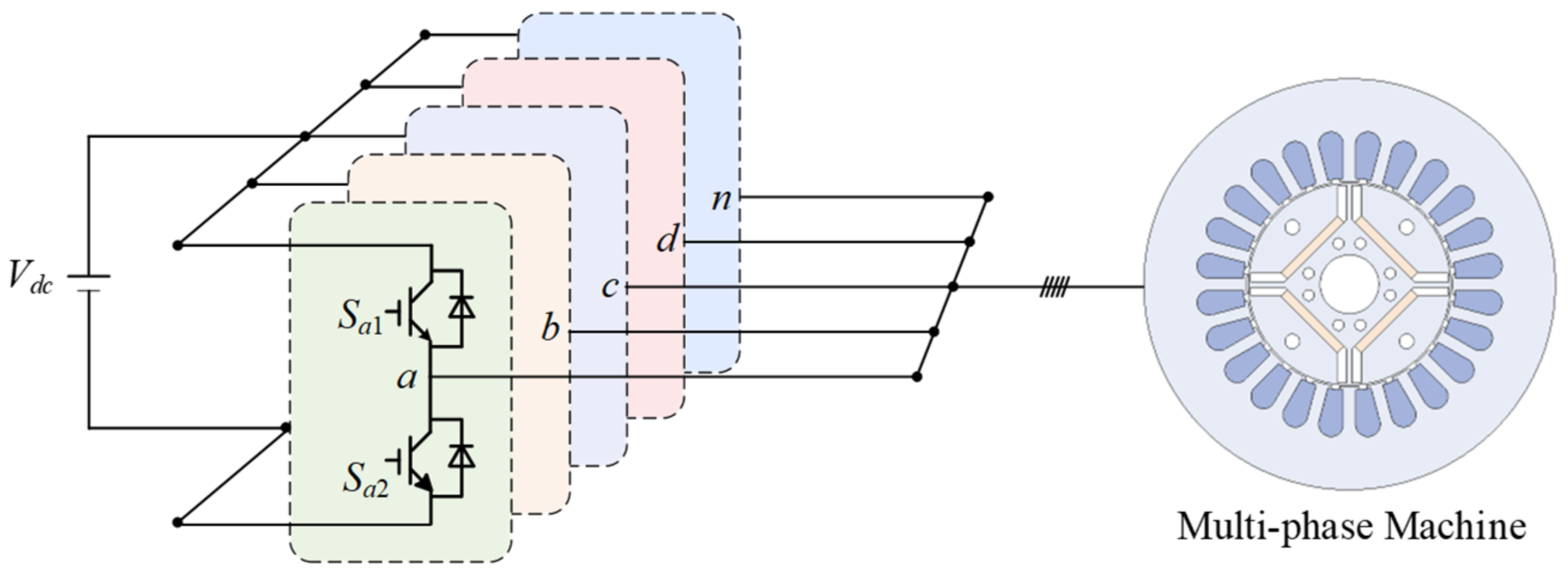
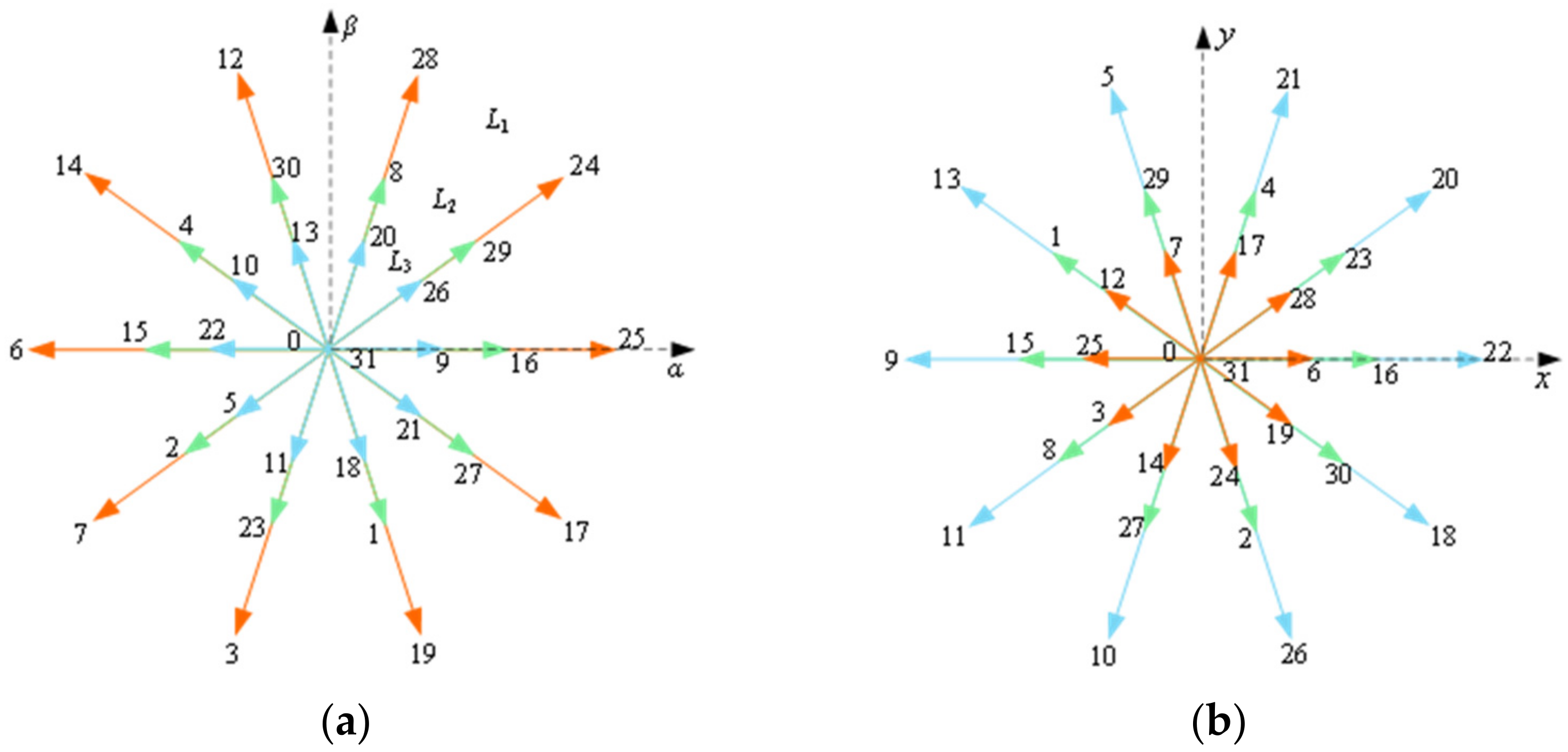
2. Multi-Phase Machine Model

A common symmetric multi-phase electric drive topology with shared neutral is shown in Figure 1, in which an n-phase machine is powered by a two-level n-phase voltage source inverter (VSI) [15]. The mathematical model of the multi-phase machine will be derived in this section.
The principle of MPC for the multi-phase machine is similar to that of a three-phase machine. However, the main difference with the three-phase machine is that the control dimension of the multi-phase machine is higher, which requires synchronous control of the voltage and current in the fundamental and harmonic subspaces [16].
To simplify the mathematical model of the multi-phase machine, the vector space decomposition (VSD) method is widely used to decouple the mathematical model. Taking a five-phase PMSM as an example, the five-dimensional variables can be decoupled into three orthogonal subspaces through the VSD [17], and the VSD transformation matrix of the five-phase PMSM with invariant amplitude criterion can be described by (1)
  T α β = 2 5 1 cos δ cos 2 δ cos 3 δ cos 4 δ 0 sin δ sin 2 δ sin 3 δ sin 4 δ 1 cos 3 δ cos δ cos 4 δ cos 2 δ 0 sin 3 δ sin δ sin 4 δ sin 2 δ 1 / 2 1 / 2 1 / 2 1 / 2 1 / 2
where δ = 2π/5 is the electrical angle between two adjacent phases.
The transformation matrix maps the fundamental and the kth = 10m ± 1(m = 1, 3, 5....) harmonics completely to the α-β subspace. The variables of this subspace are related to energy conversion. Since the amplitude of the higher harmonics is low, it can be considered that this subspace has only a fundamental component. The kth = 5m ± 2(m = 1, 3, 5....) harmonics are mapped on the x-y subspace, which is not related to the energy conversion but is related to the stator copper loss. The zero-sequence harmonics in the order of kth = 5m (m = 1, 3, 5....) are mapped in the zero subspace, which is always kept at zero for the five-phase machine with star winding connections [18].
Accordingly, by taking Park’s transform, the mathematical model of a five-phase PMSM can be expressed in a simple manner
  u d 1 u q 1 u d 3 u q 3 = R i d 1 i q 1 i d 3 i q 3 + d d t L d 1 i d 1 L q 1 i q 1 L d 3 i d 3 L q 3 i q 3 + ω L q 1 i q 1 L d 1 i d 1 + ψ f 1 3 L q 3 i q 3 3 L d 3 i d 3
where ud1/uq1, id1/iq1, and Ld1/Lq1 are the d-q axes voltage, current, and inductance in the fundamental subspace, ud3/uq3, id3/iq3, and Ld3/Lq3 are the d-q axes voltage, current, and inductance in the third harmonic subspace, ω is the rotor angular velocity, and R is the stator resistance.
Subsequently, the torque can be derived as
  T e m = 5 2 p n ψ f i q 1 + i d 1 i q 1 L d 1 L q 1 + 3 i d 3 i q 3 L d 3 L q 3
where pn is the number of pole pairs.

3. Classical MPC Schemes in a Multi-Phase Machine

Taking a five-phase PMSM as an example, which is powered by a five-phase two-level VSI with 25 = 32 switching states [19], each switching state corresponds to the VVs in the α-β subspace and x-y subspace, as shown in Figure 2. All VVs can be expressed as
u s α - β = 1 3 V d c S A + S B e j 72 ° + S C e j 144 °   + S D e j 216 ° + S E e j 288 ° u s x - y = 1 3 V d c S A + S B e j 216 ° + S C e j 72 ° + S D e j 288 ° + S E e j 144 °
where Vdc is the DC-bus voltage of the VSI, and Si (i = A, B, C, D, E) ϵ {0 1} represents the switching state of different bridge arms. “1” denotes that the upper device is ON, and “0” denotes that the lower device is ON.
Because of the redundancy of switching states, there are only 30 active VVs in the two subspaces, which can be divided into three groups, namely large vector group L1, medium vector group L2, and small vector group L3, with the amplitude of 0.6472Vdc, 0.4Vdc, and 0.2472Vdc, respectively.
According to different control objectives, there are three MPC methods, namely model predictive current control (MPCC), model predictive torque control (MPTC), and model predictive speed control (MPSC) [20,21,22,23]. The control structures of the three control methods are similar, as shown in Figure 3. The main difference lies in the prediction model and cost function.

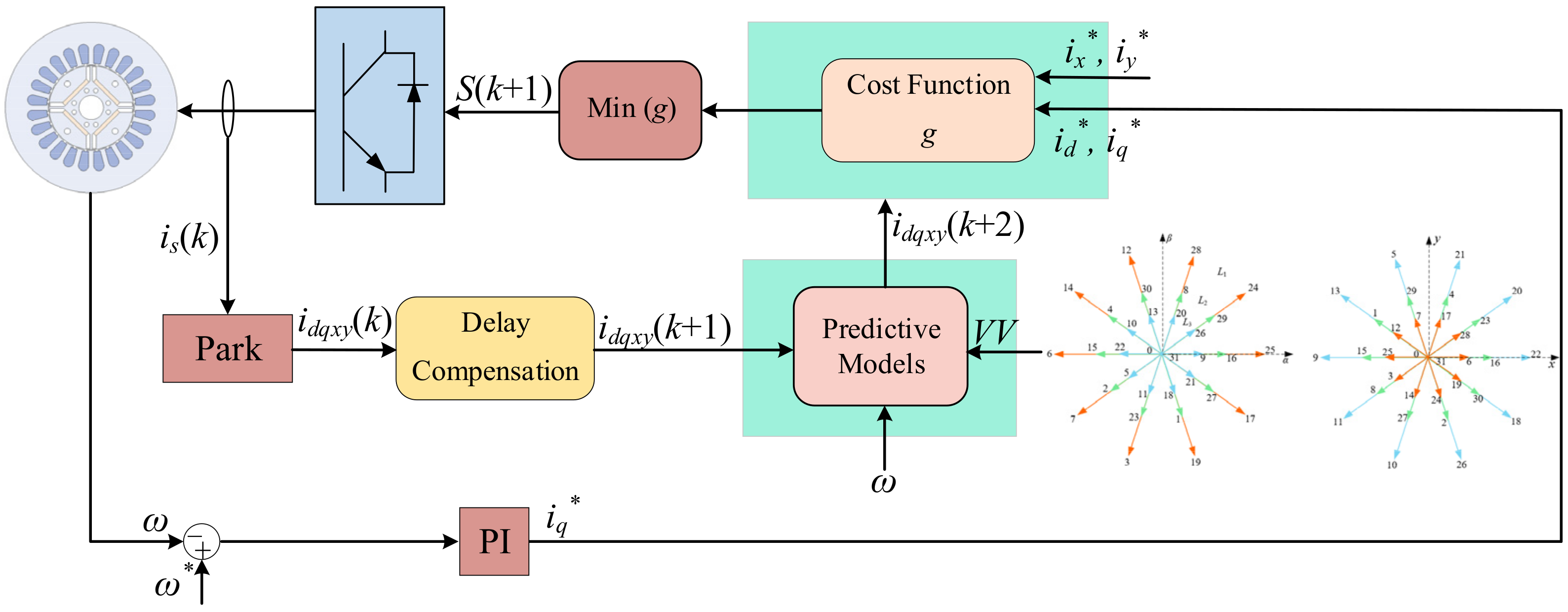
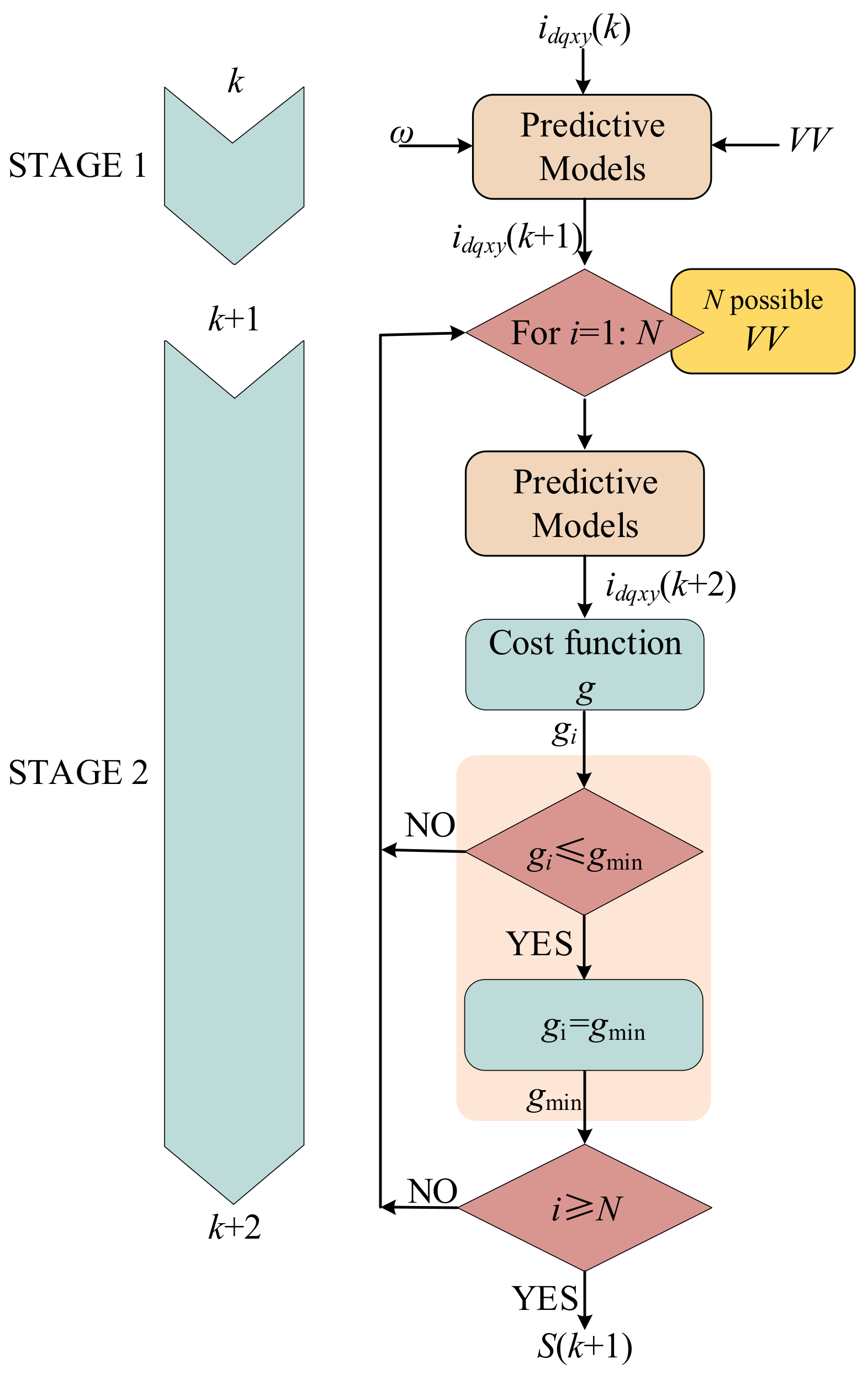
3.1. Model Predictive Current Control

The conventional MPCC control scheme of the multi-phase machine aims to optimize fundamental and harmonic currents [24]. According to the forward Euler equation, the current prediction model can be defined as
{ i d 1 ( k + 1 ) = ( 1 R L d 1 T s ) i d 1 ( k ) + ω e T s L q 1 L d 1 i q 1 ( k ) + T s L d 1 u d 1 i q 1 ( k + 1 ) = ( 1 R L q 1 T s ) i q 1 ( k ) ω e T s L d 1 L q 1 i d 1 ( k ) + T s L q 1 u q 1 ω e T s ψ f L q 1 i d 3 ( k + 1 ) = ( 1 R L d 3 T s ) i d 3 ( k ) + 3 ω e T s L q 3 L d 3 i q 3 ( k ) + T s L d 3 u d 1 i q 3 ( k + 1 ) = ( 1 R L q 3 T s ) i q 3 ( k ) 3 ω e T s L d 3 L q 3 i d 3 ( k ) + T s L q 3 u q 3
where k and k + 1 mean the current and next sampling period, respectively; Ts is the sampling period.
To improve the voltage utilization rate of the DC-bus, the conventional MPCC usually only uses the large vectors in group L1 to control the machine. The vectors in this group have the maximum amplitude in the α-β subspace, and the minimum amplitude in the harmonic subspace as shown in Figure 2, so the harmonic current can be naturally reduced. To realize the simultaneous control of the fundamental and harmonic currents, the cost function (CF) is designed as
g = i d 1 * i d 1 k + 1 + i q 1 * i q 1 k + 1 + λ i d 3 * i d 3 k + 1 + i q 3 * i q 3 k + 1
where λ is the weighting factor (WF) and id1*, iq1*, id3*, and iq3* are the current commands in the two frames, respectively.

3.2. Model Predictive Torque Control

MPTC is developed from DTC, which maintains the characteristics of the fast response of DTC. Different from MPCC, MPTC requires considering the control of torque and flux [25]. Therefore, the torque and flux need to be predicted as
T e k + 1 = 5 2 P n ψ f i q 1 k + 1 + L d 1 L q 1 i d 1 k + 1 i q 1 k + 1 + 3 L d 3 L q 3 i d 3 k + 1 i q 3 k + 1 ψ s d k + 1 = L d 1 i d 1 k + 1 + ψ f ψ s q k + 1 = L q 1 i q 1 k + 1
Then, the control performance under the action of different switching states is evaluated by the CF, and the switching state that can minimize the CF is selected for the next control period. The CF is designed as
g = T e * T e k + 1 + λ 1 ψ s d * ψ s d k + 1 + ψ s q * ψ s q k + 1 + λ 2 i d 3 * i d 3 k + 1 + i q 3 * i q 3 k + 1
where Te*, ψsd*, and ψsq* are the torque and stator flux commands, respectively.

3.3. Model Predictive Speed Control

In addition to current control, and torque control, the MPC of the multi-phase machine can also be utilized for speed control. MPSC of multi-phase machines is aimed at controlling motor speed and stator currents [26]. To predict the rotor mechanical angular velocity in the future, the prediction model is expressed as
ω m k + 1 = ω m k + T s J T e m k T L k B ω m k
The CF of the MPSC scheme mainly contains two control variables, namely rotor mechanical angular velocity, and stator current. The optimal switching state is selected by optimizing the CF, which is defined as
g = i d 1 * i d 1 k + 1 + i q 1 * i q 1 k + 1   + λ 1 i d 3 * i d 3 k + 1 + i q 3 * i q 3 k + 1   + λ 2 ω m * ω m k + 1
where ωm* is the rotor mechanical angular velocity command.
To intuitively analyze the MPC of the multi-phase machine, the general flow chart is shown in Figure 4. First, the switching state of the multi-phase inverter is discretized into a finite control set. Then, the future behavior of different control variables is predicted by using the prediction model. After that, the switching state with a minimum value of CF is selected as the optimal solution for the next control period.

4. Advanced Control Schemes of MPC in the Multi-Phase Machine

MPC methods can straightforwardly handle different constraints while providing fast dynamic responses. However, when MPC methods are applied to multi-phase drive systems, they face a variety of challenges. Some of the major technical challenges are listed in Figure 5.
Ins recent decades, several improved MPC methods have been investigated in multi-phase drive systems to address these challenges [27,28,29,30,31,32,33,34,35,36,37,38,39,40,41,42,43,44,45,46,47,48,49,50,51,52,53,54,55,56,57,58,59,60,61,62,63,64,65]. These advanced control methods will be analyzed and summarized in the following text.

4.1. MPC of the Multi-Phase Machine with Simplified Cost Function

For the CF that has multiple control objectives and cannot be normalized, the tuning of WF is tedious work, especially for the multi-phase machine, where the CF may contain multiple weighting factors compared to three-phase machines and is therefore more complex. To alleviate this challenge, several solutions have been proposed [27,28,29,30,31,32,33,34,35,36,37,38,39,40,41,42,43,44].
In [27], a simplified MPTC method is proposed, in which the VVs that can reduce the harmonic stator flux are pre-selected to reduce the harmonic current. In this method, the control variables in the harmonic subspace are not required to be constrained in the CF, thus simplifying the CF, as shown in (14)
g = T e m * T e m k + 1 + λ 1 ψ s * ψ s k + 1
Compared with the conventional CF shown in (11), the simplified CF eliminates the weighting factor λ2. However, it is still necessary to adjust λ1 to balance the control of torque and stator flux.
The optimization of WF is a challenging task because the objectives to be optimized are often in conflict [13]. Therefore, a more attractive approach is to eliminate the WF. In recent years, many techniques for eliminating WF have been investigated. In [28], a CF based on a stator flux vector is proposed, which can be expressed as
g = ψ s * ψ s k + 1
This kind of CF transforms the control variables of torque and stator flux amplitude into the stator flux vector, thus eliminating the WF.
In addition, a simplified CF based on the VV error is proposed in [29], which can directly obtain the reference voltage vector (RVV) based on the deadbeat control principle [30]. Then, the VV closest to the RVV is selected as the optimal vector. The CF is defined as
g = u s * u s k + 1
where us* is the RVV.
However, the harmonic current cannot be adjusted by using the VV-error-based CF. Therefore, in [34], a reduced-dimension CF is proposed for the six-phase machine. To ensure proper tracking of torque and flux in the fundamental subspace, the appropriate VVs are pre-selected through the location of RVV in the fundamental subspace. Then a simplified CF only containing harmonic constraints is utilized to evaluate the candidate VVs to suppress the harmonic currents. The reduced-dimension CF is defined.
g = i z k + 1
where
i z k + 1 = i s x 2 k + 1 + i s y 2 k + 1  
Furthermore, in [31], a virtual voltage vector (V3s)-based MPC method is proposed to eliminate the harmonic voltage. The principle of V3s is shown in Figure 6, which is synthesized from the VVs of groups L1 and L2 with the same direction in the α-β subspace, and the opposite direction in the x-y subspace. Therefore, the harmonic current can be eliminated by reasonably distributing the duty cycle of the two VVs in groups L1 and L2. The general form of the V3s is expressed as
V V i = d 1 V L 1 + d 2 V L 2
where VL1 and VL2 are the large and medium VV, respectively; d1 and d2 are the duty cycles of the two VVs with the value of 0.618 and 0.382, respectively. All the synthesized V3s are shown in Figure 7.
Since the x-y current has been eliminated to zero by the application of V3s, a simplified CF can be obtained, which excludes the consideration of the x-y current
g = i s α * i s α k + 1 + i s β * i s β k + 1
With the V3s method, there is no need to constrain the harmonic components in the CF [32]. Unfortunately, this method cannot compensate for the harmonic current due to the dead-time of the inverter, and the distortion of the back electromotive force of the multi-phase machine [33]. Therefore, ref. [35] proposed a modulation scheme for synthesizing the control voltage in the harmonic subspace to suppress the harmonic current. According to the deadbeat control, the dwell time range of two large VVs and two medium VVs is determined to ensure the accurate control of the fundamental subspace. Then, the harmonic voltage is optimized by the CF that only contains the x-y subspace. The CF is defined as follows
g = u s x * u s x k + 1 + u s y * u s y k + 1
where usx* and usy* are the RVVs in the x-y subspace. In this method, the modulation scheme realizes the decoupling control of fundamental and harmonic subspaces.
On the other hand, changing the structure of the CF also provides a breakthrough for the elimination of WF, namely parallel MPC [36], and sequential MPC (SMPC) [37]. The CF of parallel MPTC is implemented by a parallel structure, and the candidate vectors are optimized to ensure that the error of the control variables is within a predefined boundary. In SMPC, the CF is cascaded, which can realize the control of multi-control variables by sorting the multiple CFs. However, towing to the characteristics of the sequential structure, the evaluation sequence will affect the control performance [39,40]. In [38], a SMPCC scheme for a five-phase PMSM is proposed for the first time. According to the control priority of control variables, two sequential CFs based on maximum torque control and minimum harmonic current control are designed. The fundamental current CF and harmonic current CF are expressed as
g 1 = i d 1 * i d 1 k + 1 + i q 1 * i q 1 k + 1
g 3 = i d 3 * i d 3 k + 1 + i q 3 * i q 3 k + 1
In the maximum torque control scheme, the fundamental current CF g1 has the highest priority. Firstly, two large vectors that minimize g1 are selected from 10 large candidate vectors. Then, the harmonic current CF g3 is utilized to select the optimal vector from the two large vectors and one zero vector. In the minimum harmonic current control scheme, the harmonic current suppression is taken as the control priority. Firstly, g3 is used to select one optimal large vector, one optimal medium vector, and one zero vector as the candidate vectors. Then, g1 is minimized to select the optimal vector from the three candidate vectors.
It should be pointed out that artificial intelligence (AI) for WF optimization is a feasible solution. A study by [14] proposes a WF optimization method by combining the multi-objective particle swarm optimization method with the Pareto Optimality method for the six-phase machine. Compared with the trial-and-error method, this kind of method can find a more suitable WF to track the current better. In [41], an artificial neural network (ANN) is introduced to automatically select the optimal WF. In [42], an ANN model based on a genetic algorithm is proposed to fast and explicitly determine the optimal weighting factor. However, the training of ANN inevitably requires a large number of experimental or simulation data to ensure optimization accuracy, which will add additional computational burden to the control system and limit the promotion of this technology in industrial applications. A weighting factor design method based on a reinforcement learning algorithm is proposed. The deep deterministic policy gradient agent is used to optimize the design of the optimal weighting factor [43]. In [44], an ANN-based method is proposed, which applies a genetic algorithm as the backpropagation algorithm. Since this method is offline training, it does not increase the computational complexity.

4.2. MPC of the Multi-Phase Machine with Harmonic Current Suppression

The extension of MPC methods to multi-phase machines poses an additional challenge in terms of the regulation of harmonic current caused by the increase in control degrees of freedom [45], especially in the case of a multi-phase machine with low values of stator resistance and leakage inductance, where the MPC method exhibits unacceptable current harmonic distortions [46]. This unsatisfactory performance is mainly caused by the application of only one switching state of the inverter for the entire control period [47] since the single-vector-based MPC cannot satisfy the control requirements of both fundamental and harmonic subspaces.
The V3s-based method can not only simplify the CF but also is proven to be an effective solution for reducing harmonic currents in multi-phase drive systems [48]. Essentially, V3s is the combination of two switching states that make the average x-y voltage equal to zero [49,50]. However, since the amplitude and direction of a virtual vector are fixed in the α-β subspace, the regulation of the α-β subspace is not flexible. To mitigate this drawback, two sets of V3s with different amplitudes are employed [51], which expands the number of candidate V3s to 25. Compared with conventional V3s-based MPC, the distortion of α-β current at low speed is improved. A study by [52] proposed a V3s-based MPC method with duty cycle regulation, where the candidate VV is composed of one V3s and one zero VV. Nevertheless, the improvement of the control performance is still limited because of the constant direction of the synthesized vector. Another study [53] proposes a MPC method based on two V3s to improve the control performance in the fundamental and harmonic subspaces since the combination of two V3s can provide better voltage tracking accuracy. However, the V3s used above have static properties because they are determined off-line, that is, the duty ratio of the large vector to medium vector is fixed. Although the V3s make the average voltage in the x-y subspace equal to zero, the low-frequency current harmonics that maps to the x-y subspace will appear towing to the asymmetric windings of the machine, the non-linearity of the inverter, etc. In response to this challenge, a Bi-subspace MPC method based on V3s is proposed in [54], which uses dual V3s to achieve independent control of the fundamental and harmonic currents. Moreover, to further reduce the current tracking error, a predictive current control scheme based on space vector modulation (SVM) and V3s is proposed in [57]. In this scheme, two vectors are combined with zero vectors to enhance the control accuracy in the two subspaces. Experimental results indicate that this scheme can achieve better α-β current tracking and x-y current reduction.
On the other hand, the multi-vector-based MPC is another effective method to reduce the current harmonics [60,61,62,63,64,65]. In [58], a double-vector-based MPCC scheme is proposed to improve the tracking accuracy and DC-link voltage utilization for a five-phase drive system. In the conventional scheme, enumerating all possible double-vector combinations ( C 21 2 = 21 ! / 2 ! * 21 2 ! = 210 ) requires a large amount of computation. This scheme proposed a simplified approach, which first selects five VVs (four active VVs and one zero VV) as the candidate VVs according to the sector where the RVV is located and reduces the possible vector combinations C 5 2 = 5 ! / 2 ! * 5 2 ! = 10 , as shown in Figure 8. Then, the duty cycle of each VV is optimized online to reduce the deviation between the synthesized vector and the RVV. Finally, the optimal vector combination is selected by minimizing the CF. However, the control accuracy is limited because only two vectors are applied in one control period. To better improve the control performance, the concept of the dynamic vector is proposed in [55], and the current quality is improved by optimizing the dwell time of two active vectors and one zero vector online according to the tracking error of each sampling period. In [57], the concept of the smart vector is introduced, which adopts three active vectors to form the smart vector through the online smart search. Compared with the previous strategy, the smart vector can cover a larger area, thus providing more accurate control effect. In [61], a modified control scheme named modulated model predictive control (M2PC) is proposed. M2PC is a combination scheme based on SVM and MPC [62], which can generate any fundamental VV in the α-β subspace by using two adjacent large vectors and one zero vector in a certain sector, as shown in Figure 9a. However, the disadvantage of M2PC is the low tracking accuracy in the α-β subspace, since three vectors cannot simultaneously ensure the tracking accuracy of the two subspaces. Further, a multi-vector-based novel-M2PC (NM2PC) is proposed in [63], which extends the concept of M2PC to medium vectors in the α-β subspace. Since NM2PC uses more vectors, as shown in Figure 9b, the control effect of the synthesized vector is more accurate, and the steady-state errors are better reduced. In [58], a multi-vector MPC based on three adjacent large vectors and a specific zero vector is proposed. The three adjacent large vectors can achieve zero average voltage in the x-y subspace to minimize the harmonic current. On the other hand, the insertion of a specific zero vector can not only reduce the fundamental current ripple but also reduce the switching frequency loss. In [60], a predictive torque control scheme based on the deadbeat principle and discrete space vector modulation (DSVM) is proposed to improve the control accuracy. Compared with the traditional method, DSVM can provide more vectors with different amplitudes and directions, as shown in Figure 10, where the color dots represent the generated vectors. It should be noted that the multi-vector scheme including a zero vector improves the control accuracy, but reduces the utilization rate of DC-link, whereas using a large VV alone ensures a high utilization rate of DC-link, but at the cost of poor control performance at low speed. Therefore, a hybrid solution is proposed in [64], which combines multi-vectors and large vectors to form a hybrid control set to obtain higher current quality, and satisfactory DC-link utilization. Furthermore, to achieve independent control of fundamental and harmonic currents, a decoupled control scheme of α-β and x-y subspaces is proposed in [35]. In this scheme, five vectors are applied during the whole control period, namely, two large vectors, two medium vectors, and one zero vector. Firstly, the dwell time range of the four active vectors is determined according to the RVV of the fundamental subspace. Then, the final dwell time is determined based on the RVV of the x-y subspace. Similarly, ref. [65] introduces a direct harmonic control scheme for the six-phase machine. It also firstly determines the dwell time range of the multiple active vectors according to the control requirement in the α-β subspace. Different from [35], the final dwell time is determined by cost function optimization.

4.3. MPC of the Multi-Phase Machine with Computational Complexity Reduction

Essentially, MPC is an optimization control method, in which the optimization algorithm is utilized to solve the optimization issues based on the prediction model and CF. The complex prediction model and a large number of VVs in a multi-phase inverter require a lot of calculation amounts and are therefore very time-consuming [66]. For this reason, different solutions have been proposed to mitigate this challenge [67,68,69,70,71,72,73,74,75,76,77,78,79,80].
The first class of methods is the V3s-based strategy [67]. Since the average voltage in the harmonic subspace is zero, there is no need to predict the harmonic variables, and the evaluation of the harmonic variables by the CF is also eliminated. This is one of the commonly used methods to reduce the computational complexity in the MPC of the multi-phase machine [68]. It should be noted that the V3s-based MPC cannot achieve the standard PWM switching sequence, which makes the hardware implementation difficult. For easy hardware implementation, the V3s of the nonstandard switching sequence are ingeniously replaced by the corresponding equivalent virtual vector in [69], which simplifies the modulation process.
The second common method is to reduce the number of prediction vectors based on the location of the RVV [70]. The RVV can be derived in different ways, such as the deadbeat current control [71], which is derived as
i d * = i d k + 1 i q * = i q k + 1
where id* and iq* are the reference current of the d-q axes.
Based on the mathematical model of the machine, the RVV can be deduced as
u d * = L d T s i d * R L d T s i d k + 1 ω e L q i q k + 1 u q * = L q T s i q * R L q T s i d k + 1 + ω e L d i d k + 1 + ψ p m
where ud* and uq* are the RVV of the d-q axes.
Then, the RVV in the α-β subspace can be expressed with Park transformation
u α * = cos θ u d * sin θ u q * u β * = sin θ u d * + cos θ u q *
Subsequently, the position of the RVV in α-β subspace is calculated as
θ r e f = arctan u α * u β *
In [72], a multi-vector-based MPC for a five-phase machine with a geometry solution is proposed, in which the suitable candidate VVs are pre-selected according to the position of the RVV, and then a simple geometric method is utilized to calculate the duty cycle. This method can not only quickly determine the optimal VV, but also simplify the calculation of the duty cycle. A study by [73] proposes a MPTC scheme based on double V3s for five-phase PMSM. The optimal V3s are directly selected according to the position of the RVV, which avoids the prediction of all candidate V3s. In addition, the WF is eliminated, thus reducing the calculation workload. In addition, in view of the complicated derivation of the RVV in the deadbeat-direct torque and flux control, ref. [74] proposes a simplified algorithm based on load angle control. This algorithm directly deduces the change of the load angle from the torque error, and only needs to be implemented in the stationary frame without complex coordinate transformation. Another study by [75] proposes two simplified methods for calculating RVV in the synchronous rotating frame. The first method is based on the stator flux differential. By reducing the order of the calculation equation, the calculation process of the RVV only includes basic arithmetic operations and does not involve the square root. The other simplified algorithm is based on complex power derivation, which introduces a novel reactive torque parameter to reduce the complexity.
The third feasible method to reduce the computational cost is to pre-eliminate the undesired VVs according to the errors of torque and stator flux [76], which can be achieved by a switching table, as shown in Figure 11. However, this kind of method usually only uses one VV for the whole control period, and the control performance is not satisfactory. A common improvement method is to adjust the duty cycle of the applied VV by inserting a zero vector [77]. However, the complexity of the algorithm inevitably increases towing to the duty cycle calculated by the derivative method. In [78], a simplified MPC method for the six-phase machine is proposed to reduce the steady-state ripple without calculating the duty cycle, in which the optimal VV is determined by a two-step switching table. Compared with the conventional MPTC, the prediction times of VV are reduced. Moreover, to avoid the tedious calculation of the duty cycle, the discrete duty ratio is directly assigned to the selected vectors to establish a candidate control set of vectors with different amplitudes. It is worth noting that the two-step switching table is relatively complex, as it involves the consideration of fundamental and harmonic variables. Therefore, ref. [68] proposes a computationally efficient MPC for the five-phase machine. Through analysis, the RVV of the adjacent control periods is unchanged. To simplify the enumeration optimization process, four candidate vectors are directly selected according to the RVV of the previous control period, which eliminates the deadbeat calculation process. In addition, in [79], a simplified DTC strategy based on the predictive control principle is proposed for two series-connected drive systems. The optimal VV is directly selected according to the principle of minimum zero sequence current, minimum torque, and flux errors. In [80], a hybrid control scheme of MPC and DTC is proposed. Different from the deadbeat solution, this method first determines the direction vector according to the DTC principle, and then the VV located in the same sector as the direction vector is selected as the candidate vector, which avoids the enumeration predictions of all vectors.
The advantages and disadvantages of the above three kinds of methods are compared, as shown in Table 1.

4.4. MPC of the Multi-Phase Machine with Robustness Improvement

The control performance of MPC is highly dependent on the accuracy of the parameters of the control system. The initial model parameters may not match the actual system parameters, and the disturbance caused by the inaccurate model restricts the development of MPC. In addition, compared to a three-phase machine, the prediction model of a multi-phase machine is more complicated, which not only contains fundamental variables, but also harmonic variables are also involved, which increases the parameter sensitivity accordingly. Therefore, the heavy reliance on the system model in the multi-phase machine is more challenging than that of the three-phase machine. To improve the performance of MPC under parameter mismatches or other unmodeled dynamics, relevant studies are mainly divided into five categories.
The first type method applied to improve the robustness of MPC is to improve the prediction model [81]. With the increase of machine speed, the sampling points during the single current cycle are continuously reduced, and the prediction equation based on Euler’s method will inevitably cause a large error. For the sake of reducing the prediction error, the sampling period Ts is divided into n sub-periods, and the VV corresponding to each sub-period can be calculated as
u c i = L T s / n ( i c ( k + i + 1 n ) i c ( k + i n ) ) + R i c ( k + i n ) + e c ( k + i n )
where uc(i) is the VV at k + (i/n)-th sampling period, i = {0,1,2…n − 1}, c ∈ {α, β, x, y}.
By accumulating both sides of (25), the VV during one sampling period is
u c k = 1 n i = 0 i - 1 u c i = L T s i c t + 1 i c t + 1 n i = 0 i - 1 ( R i c ( t + i n ) + e c ( t + i n ) )
According to (26), the discretization accuracy increases with the increase of n. When n goes to infinity, the cumulative part in (26) can be transformed into an integral form
u c k = L T s i c t + 1 i c t + k T s ( k + 1 ) T s ( R i c ( ε ) + e c ( ε ) ) d ε
Therefore, through the improved prediction model shown in (27), the discretization error can be reduced, thereby improving the prediction accuracy.
It should be noted that the stator current prediction model in the conventional MPC is an open-loop structure, as shown in (5). If there is a prediction error, it cannot be corrected in real-time. To achieve accurate prediction of stator current, ref. [82] proposed a stator current prediction model based on a closed-loop structure. According to (5), the stator current equation could be rewritten in the complex field
i d q ( s ) = 1 R 1 L R s + 1 v d q ( s ) j ω e L i d q ( s ) + ψ f
where s is the Laplace operator.
Using the step response technique, the accurate stator current prediction model can be obtained
i d q ( k + 1 ) = i d q ( k ) e T s τ + V s u m ( k ) 1 R ( 1 e T s τ )
where τ = L/R, and Vsum (k + 1) represents the compensation part, which can be calculated as
V s u m ( k ) = V s u m ( k 1 ) + k p + T s k i i s e r r o r ( k ) + k p i s e r r o r ( k ) + V d q ( k ) + ω e L q i q ( k ) j ω e L d i d ( k ) j ω e ψ f
where kp and ki are the proportional and integral coefficients, which will affect the prediction accuracy and system stability. The stator current prediction model based on the closed-loop structure is shown in Figure 12.
In addition, to reduce the prediction error of stator flux, ref. [82] proposes a hybrid closed-loop stator flux prediction model based on the current model and voltage model. The hybrid prediction model can be expressed as
ψ d q s ( k + 1 ) = V ψ - e r r o r ( k ) + ψ d q s ( k ) T s R i d q ( k ) T s ω e ψ q ( k ) + j T s ω e ψ d ( k ) + T s V d q ( k )
where Vψ-error(k) is the compensation part, which can be calculated as
V ψ - e r r o r ( k ) = k p + T s k i ψ d q c ( k + 1 ) ψ d q s ( k + 1 ) + k p ψ d q c ( k ) ψ d q s ( k ) + V ψ - e r r o r ( k 1 )
where ψdqs(k + 1) and ψdqc(k + 1) represent the stator flux prediction values of the voltage model and current model, respectively.
Figure 13 shows the hybrid stator flux prediction model, where the regulator is designed to achieve a smooth transition between the voltage and current models.
In [83], a novel MPCC scheme with flux parameter eliminating is proposed to reduce the computational burden of multiple parameter estimation. In this scheme, the flux parameter can be replaced by the inductance information, since the flux information is only included in the expression of the q-axis current, as shown in (33)
ψ f ( k ) = u q ( k ) R i q k ω e ( k ) L k i q ( k ) i q ( k 1 ) T ω e ( k ) L k i d ( k )
Then, according to (33), the flux information at the instant of k, k − 1, and k − 2 can be rewritten as
ψ f ( k ) = u q ( k ) R i q k ω e ( k ) L k i q ( k ) i q ( k 1 ) T ω e ( k ) L k i d ( k ) ψ f ( k 1 ) = u q ( k 1 ) R i q k 1 ω e ( k 1 ) L k 1 i q ( k 1 ) i q ( k 2 ) T ω e ( k 1 ) L k 1 i d ( k 1 ) ψ f ( k 2 ) = u q ( k 2 ) R i q k 2 ω e ( k 2 ) L k i q ( k 2 ) i q ( k 3 ) T ω e ( k 2 ) L k 2 i d ( k 2 )
To improve the accuracy of flux prediction, it is necessary to average the flux information at the instant of k, k − 1, and k − 2 to obtain the final flux replacement expression
f l ψ f = ψ f k + ψ f k 1 + ψ f k 2 / 3
According to (34) and (35), the flux information can be represented by the inductance information. Therefore, the flux parameter in the prediction model can be replaced by the inductance parameter, which eliminates the influence of flux mismatch.
In addition, refs. [84,85] propose an improved MPC that considers error compensation in the prediction model. In [84], the measured current information is added to the current prediction model to improve the prediction accuracy. In [85], a weighted discrete-time integral action is added to the calculation of the RVV to compensate for the error caused by parameter variation. In [86], to realize the accurate prediction of stator current, a feedback mechanism is added to the open-loop stator current prediction model. By introducing a correction factor, the stator current error of the previous period is compensated for the stator current prediction of the next control period. For the inductance mismatch problem, ref. [87] proposes a torque and flux slope-based predictive model, which eliminates the involvement of inductance parameters, and thus reduces the sensitivity to inductance mismatch.
On the other hand, machine parameter identification and real-time parameter update are other ways to improve parameter robustness. The common online parameter estimation strategies include projection algorithm [88], extended Kalman filter (EKF) [89], neural network [90], fuzzy control method [91], Particle swarm optimization (PSO) [92], sliding mode observer (SMO) [93], recursive prediction error method (RPEM) [94], and model reference adaptive system (MRAS) [95]. In addition, there are several other methods available for the online identification of system parameters, such as Recursive least squares (RLS) [96], the gradient descent algorithm [97], and the Gauss–Newton method [98]. A study by [96] proposes a parameter estimation strategy based on RLS, which can accurately estimate the overall parameters to attenuate the sensitivity of the drive system to parameters. In [99], a data-driven RLS method is proposed, which does not require a pre-defined model with the machine parameters, and thus has greater flexibility than the traditional RLS method. In [97], an improved gradient method is proposed to identify multiple machine parameters with low complexity, since no complex observer and tedious tuning work is needed. In [98], a deadbeat predictive current control based on the Gauss–Newton method is proposed, which can automatically correct the resistance and inductance parameters. Another study by [100] proposes a robust MPCC based on a d-q axes current error to extract the inductance and flux parameters r. However, it requires two control loops to extract the flux and inductance, and this structure is relatively complicated. Therefore, ref. [83] proposes an improved method to extract the error between the actual inductance and the model inductance by a simple integral controller. Moreover, the flux information can be replaced by the inductance information. In addition, ref. [101] proposes an updating mechanism that can calculate the compensation factors to eliminate the current errors caused by model parameter mismatch. In [102], a MPCC method for real-time updating of parameters is proposed, which is realized by measuring the stator current and applying VVs of two adjacent control moments. In addition, to improve the reliability of the system, the predicted current is corrected by EKF.
The third type applied to improve the robustness of MPC is using the disturbance observer to estimate the disturbance and adds the observed disturbance to the controller through feed-forward compensation. In [103], a robust MPTC method based on the active disturbance rejection control method is proposed, which improves the accuracy and robustness of torque prediction by using a second-order disturbance observer. In [104], an improved MPC method based on an extended high-gain state observer is proposed, which utilizes the disturbance estimation technology instead of an integral controller to boost the control performance under different loads. Similarly, a disturbance feed-forward compensation method is proposed in [105] to improve the robustness of MPTC against load disturbances and parameter mismatches. In [106], a generalized proportional-integral observer-based MPC is proposed to reduce the influence of load disturbance and motor parameter variation. For the machines with non-sinusoidal back electromotive force, a discrete-time disturbance observer is proposed in [107] to mitigate the unmodeled disturbances. In [108], the parametric uncertainties and unmodeled disturbances are treated as concentrated disturbances, and a disturbance observer is utilized to estimate these disturbances for reducing steady-state errors. In [109], a robust MPC method with the exogenous variable model is proposed to boost the current tracking capability of the multi-phase drive system. In [110], an incremental model is utilized to eliminate the involvement of the permanent magnet flux parameter in the prediction model. In addition, an ESO is applied to improve the resistance to inductance interference. In [111], a torque disturbance observer-based MPC with the generalized proportional integral observer and SMO is proposed for system parameter variation and load torque perturbation. In [112], a disturbance observer-based MPC method for six-phase PMSM is proposed, which reduces the harmonic content of low-order current caused by unmodeled dynamics.
The fourth type is model-free predictive control (MPFC) [113]. The control diagram of MPFC is shown in Figure 14, which does not require the parameters of the system, but only the current variations information stored in the lookup table (LUT) under different VVs. The prediction accuracy will be degraded in the multiple continuous control periods without the utilization of a basic VV. To avoid this problem, a force-update algorithm is proposed in [114], where if one of the basic VVs is not applied to the predefined control periods, a basic VV will be force-applied to the following control period. However, the optimization of CF is not considered, and the steady-state performance is sacrificed. To get rid of the problem of the current stagnation update, ref. [115] proposes a current prediction error model to reconstruct the prediction model. On this basis, RLS is used to identify the machine parameters to improve prediction accuracy. Then, a smart update algorithm is proposed in [116], which keeps the current variations information up-to-date according to the current information of the previous three control periods, and then selects the optimal VV through the CF. In [117], a MFPC method for the three-level inverter-fed PMSM is proposed, which proposes an improved synchronous update method to increase the current difference updating frequency. In addition, to reduce the computational complexity, a simple selection method of candidate VV is adopted. Moreover, the ultra-local model-based MFPC has been investigated to improve the control performance [118,119,120]. However, these methods require complex tuning efforts, and the control performance depends heavily on the sampling frequency. In [121], a robust MFPC based on an ultra-local model and ESO is proposed for a six-phase drive system. By reasonably assigning the dwell time of the virtual vector and the zero vector during one control period, the coordinated control of fundamental and harmonic currents is realized with robustness improvement. In addition, to improve the steady-state performance, the MFPC method is extended to apply multiple VVs [122].
The fifth type to improve parameter robustness is to change the structure of the controller. Studies by [123,124] add the error term of the control variables into the CF to improve the parameter robustness. In [120], the past prediction errors are added to the CF, and a WF is also introduced to achieve the reduction of the steady-state errors. In [124], a novel CF in the form of proportion-integral is designed to replace the traditional CF to compensate for the prediction errors caused by parameter mismatches. In [125], a simple and effective method is proposed to improve the robustness of the system against inductance uncertainty by using current prediction errors. This method utilizes a parallel compensation structure to compensate for the predicted current, which is easy to implement. In [126], an online calculation module is proposed to compensate for the voltage deviation caused by parameter mismatch. In [127], a compensation structure based on d-q axes current errors is proposed to accurately predict the stator flux. In addition, refs. [128,129] propose a prediction model based on the measured stator current information for successive sampling periods to achieve the real-time correction of the stator current. Furthermore, ref. [130] proposes a closed-loop error compensation scheme with a simple feed-forward structure, which does not require any observer to estimate the disturbance or identify the parameters. In [131], a modified scheme of adaptive reference correction current injection is investigated to compensate for current errors caused by model parameter mismatch. It is easy to implement because only the integrator is required to obtain the compensation term of the reference current, as shown in Figure 15. Based on the analysis of the MPC methods with robustness improvement, the comparison of performance, complexity, and disadvantages are summarized in Table 2.

4.5. MPC of Multi-Phase Machines with Fault-Tolerant Operation

In recent years, the application of MPC has been expanded to fault-tolerant control of multi-phase machines [132,133,134]. Different from FOC and DTC, which are cumbersome to realize fault-tolerant control, MPC technology only needs to select appropriate fundamental and harmonic control variables, design corresponding prediction models, and CF [135]. Figure 16 shows the fault-tolerant MPCC scheme of a five-phase PMSM under OCF operation [136].
Since MPC relies heavily on the accurate prediction model of the control system, establishing the mathematical model of the multi-phase machine under fault conditions and deducing the space VV of the inverter is essential for implementing fault-tolerant MPC algorithms [137]. Taking a five-phase PMSM with the A-phase OCF as an example, the characteristics of the system are changed from a five-phase symmetric system to a four-phase asymmetric system, while the control degrees of freedom are reduced [138,139].
Combining with the inverter states after the fault, the phase voltage expression of the non-faulted phase can be obtained as
V B V C V D V E = V d c 4 3 1 1 1 1 3 1 1 1 1 3 1 1 1 1 3 S B S C S D S E
After the single-phase OCF, the number of switching states of the five-phase inverter is changed from 32 to 16, as shown in Figure 17. By using the reduced-order decoupling transformation in (37), the five-phase variables can be transformed into the two subspaces [140]
  T = 2 5 cos δ 1 cos 2 δ 1 cos 3 δ 1 cos 4 δ 1 sin δ sin 2 δ sin 3 δ sin 4 δ sin 2 δ sin 4 δ sin 6 δ sin 8 δ 1 1 1 1
where δ = 2π/5. Accordingly, the reduced order Park transform can be expressed as
  T P = cos θ sin θ 0 0 sin θ cos θ 0 0 0 0 1 0 0 0 0 1
where θ is the rotor angle.
According to (37) and (38), the mathematical model under single-phase OCF in the synchronous rotating coordinate system can be written as
  u d 1 u q 1 u y = R i d 1 i q 1 i y + d d t L d 1 i d 1 L q 1 i q 1 L l s i y + ω L q 1 i q 1 L d 1 i d 1 + ψ f 1 3 L q 3 i q 3
where Lls is leakage inductance.
Then, the prediction model of the five-phase machine under single-phase OCF can be deduced by using the forward Euler method
i d 1 k + 1 = 1 R L d 1 T s i d 1 k + ω e T s L q 1 L d 1 i q 1 k + T s L d 1 u d 1 i q 1 k + 1 = 1 R L q 1 T s i q 1 k ω e T s L d 1 L q 1 i d 1 k + T s L q 1 u q 1 ω e T s ψ f L q 1 i y k + 1 = 1 R L l s T s i y k + T s L l s u y k
where iy(k) uy(k) are the stator current and voltage of the y-axis at instant k.
It should be noted that through this transformation, the mathematical model under single-phase OCF is the same as the normal operation. The loss of degrees of freedom is reflected as the x-axis component is uncontrollable [141], in which the x-axis current has equal amplitude but opposite phase-angle to the α-axis current, i.e., isx = −i. Therefore, the x-axis current is removed from the prediction model, and the cost function under OCF is expressed as
g = i d * i d k + 1 + i q * i q k + 1 + λ i y * i y k + 1
In the case of single-phase OCF, the reference harmonic current can be controlled by different optimization criteria, including the minimum copper loss (MCL) criterion, and maximum torque (MT) criterion [142]. For example, the maximum output torque control can be achieved by controlling isy* = 0.2631i*, and the minimum copper loss control can be achieved by controlling isy* = 0.
After single-phase OCF, the number of candidate VVs for the multi-phase machine is still large, which leads to a large computational effort to optimize. In [139], a fault-tolerant MPCC method with a simplified control set is proposed, which takes the VV with the minimum amplitude in harmonic subspace as the control set to reduce the number of candidate VVs. In [141], a MPC scheme based on the reference fundamental and harmonic vectors is proposed to reduce the number of candidate active VVs from 15 to 3. In addition, ref. [138] proposed an improved fault-tolerant MPTC scheme to reduce the number of predictive VVs by determining the quadrant where the flux error vector is located. However, the computational cost is still high because of the harmonic current prediction. In addition, the above schemes are not sufficient to achieve optimal control performance due caused by only a single switching state being utilized throughout the control period. In [140], a MPTC scheme based on SVPWM is proposed for the OCF operation of a five-phase machine, which improved the steady-state performance of the control system. However, it is difficult to adjust the WF of the harmonic component in the CF. Therefore, a fault-tolerant MPC scheme based on V3s is proposed in [143], which not only simplifies the prediction model but also eliminates the turning of the WF. In [144], an improved V3s- based fault-tolerant MPTC with a deadbeat solution is proposed to quickly select the optimal vectors. In addition, the steady-state error is reduced by inserting the zero vector, and the dwell time of each vector is determined by a simple geometric principle. Moreover, ref. [145] proposes an MPCC method with continued modulation technology, which reconstructed the distribution of the post-fault VVs and compensated the back-EMF of the fault phase. A study by [146] proposes an improved fault-tolerant MPC with SVPWM solution, in which the reconstructed V3s are utilized to synthesize the reference vector, and the candidate vectors can be selected quickly by the principle of deadbeat control, thus reducing the computational burden.
Compared with a fault-tolerant MPC based on the order-reduction decoupling transformation method, some scholars proposed simplified MPC schemes without reconstruction of the transformation matrix. A study by [147] evaluates the performance of the V3s-based MPC to achieve fault-tolerant operation without changing the controller topology after OCF. The experimental results show that the V3s-based MPC shows good behavior after faults. However, the spatial position of the V3s has been shifted without proper compensation. In [148], an improved MPC method based on a health transformation matrix is proposed to deal with the single-phase OCF. To compensate for the shift of the VVs under OCF, a disturbance term is added to the candidate vector to accurately predict the machine states. Although the prediction times are reduced by selecting the outermost vectors as the control set, the harmonic variables still need to be predicted. Therefore, an improved MPCC compensation method based on V3s is proposed in [149]. By compensating for the basic VVs, 24 new V3s are constructed, avoiding the turning of WF.
The comparison of fault-tolerant control schemes with and without changing the control structure is shown in Table 3. The methods based on reduced-order decoupling transformation can establish the post-fault model and have better prediction accuracy. In contrast, the methods without reconstruction of the transformation matrix are easier to implement, but at the cost of reducing control performance.

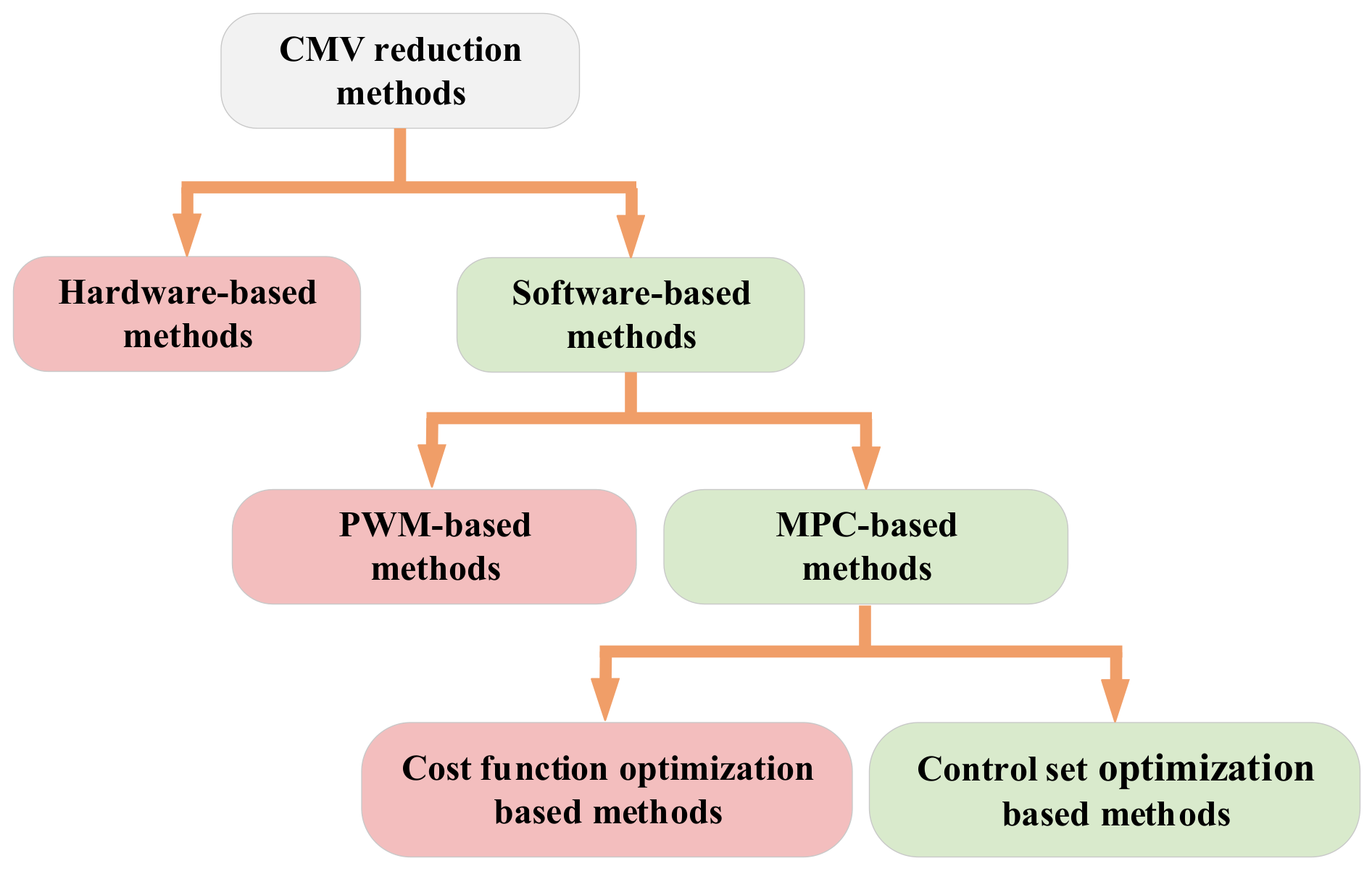
4.6. MPC of Multi-Phase Machines with CMV Reduction

Similar to three-phase machines, multi-phase machines also suffer from CMV, which is the major source of bearing voltage and current and is detrimental to the reliability of the drive systems [150]. In a multi-phase control system, CMV is defined as the voltage between the midpoint of the DC-bus and the neutral point of the machine. Taking two-level five-phase PMSM as an example, CMV can be expressed as
V C M = V d c 5 S a + S b + S c + S d + S e V d c 2
According to (42), the zero vectors generate large CMV, the medium vectors generate medium CMV, and the small and large vectors generate small CMV, with amplitudes of ±0.5Vdc, ±0.3Vdc, and ±0.1Vdc, respectively. The common CMV suppression methods are shown in Figure 18. Among them, hardware-based methods are more costly because of the requirement of additional hardware equipment, whereas software-based methods are more economical and promising. Generally, MPC-based CMV suppression methods can be divided into two categories, namely, the CF-based optimization methods, and the control set optimization-based methods [151,152,153].
For the first type of MPC method, the key is to design a multi-objective CF to control the multi-subspace variables and CMV by tuning the WF to balance the steady-state performance and CMV reduction. In [151], a MPCC method is proposed to reduce the peak value of CMV by introducing two different WF to adjust the proportion of CMV with different amplitudes. The CF is defined as
g = i s α * i s α k + 1 + i s β * i s β k + 1 + λ 1 i s x * i s x k + 1 + i s y * i s y k + 1 + λ 2 V C M L + λ 3 V C M M
where VCML and VCMM are the CMV of the large and medium VVs, respectively.
A study by [150] proposes a MPTC method with a new CF to reduce CMV. The CF includes not only torque and flux but also the x-y currents, CMV, and switching frequency, which is expressed as
g = T e m * T e m k + 1 + λ 1 ψ s * ψ s k + 1 + λ 2 ψ x * ψ x k + 1 + ψ y * ψ y k + 1 + λ 3 V C M + λ 4 C S F
where VCM is the value of CMV, and CSF is the switching frequency.
Although the CMV can be reduced to some extent by CF optimization, it is a time-consuming task to adjust the WF for multiple control objects, and different WF can lead to different current distortions and CMV.
In response to these challenges, the second type of MPC method is to reduce the CMV by eliminating the VVs in the control set that generates large CMV. In [152], an improved MPC method for CMV suppression is proposed for a five-phase inverter, which reduces the CMV by 80% with the utilization of large and small VVs with lower CMV amplitudes. In [153], a simplified control set-based MPCC method involving only five VVs is proposed. For different voltage/current requirements, the five different VVs are optimized to achieve the reduction of CMV. Although the prediction of only five vectors improves the computational efficiency, the current quality seriously deteriorates. In [154], a novel MPTC method with CMV elimination is proposed for a five-phase machine powered by a three-level inverter, in which the control set of a total of 243 VVs is simplified to a control set of 31 VVs with a low amplitude of CMV, and two series and independent CFs are utilized to select the optimal VVs. To further simplify the CF, a V3s-based MPCC method is proposed in [155], which uses only the vectors that generate small CMV to synthesize the new V3s, and the control block diagram is shown in Figure 19. According to the above analysis, the large VVs generate small CMV; therefore, three adjacent large VVs are selected in this method to construct the new V3s, and the principle is expressed as follows
0.2472 V d c d 1 cos 2 π 5 + d 2 cos π + d 3 cos 2 π 5 = 0 0.2472 V d c d 1 sin 2 π 5 + d 2 sin π d 3 sin 2 π 5 = 0
where d1, d2, and d3 are the duty cycles of the three adjacent large VVs, which are 0.382, 0.236, and 0.382, respectively.
The new synthetic V3s are shown in Figure 20. Therefore, the proposed MPCC scheme enables inherent CMV suppression and harmonic current reduction. Similarly, to suppress the CMV and current harmonics of a seven-phase VSI, a simple MPCC scheme is proposed in [156], which takes 14 V3s as the control set. In this method, the V3s are synthesized by the VVs with the largest amplitude in the fundamental subspace with the lowest CMV, and the voltage components in the two harmonic subspaces are zero. Therefore, multiple WFs are eliminated in the CF. In [157], a MPCC method with inherent rejection characteristics of CMV is proposed for a five-phase VSI, in which four adjacent large VVs are utilized to synthesize V3s. The dwell time of the V3s is optimized by introducing the duty cycle optimization technique to reduce the harmonic current. In addition, the zero vector is replaced by two opposite large VVs, thus further reducing the CMV. However, the V3s-based MPC methods for suppressing the CMV have the drawback of low DC-link utilization. To address this problem, an improved MPCC method is proposed in the literature [158], which improves the utilization of the DC-link while reducing CMV. As mentioned in [159], the existence of dead-time may lead to a large CMV. Therefore, the effect of dead-time on CMV is considered in [160]. However, it requires a field programmable gate array, which increases the hardware complexity. For the sake of reducing CMV with low hardware cost, a novel MPC method for suppressing CMV during dead-time is proposed in [161]. In this method, the combination of VVs that may generate large CMV in dead-time is pre-excluded. However, it does not make full use of all possible VVs, resulting in large current ripples. According to the analysis in [160], not all non-adjacent and non-opposite VV combinations can generate large CMV, so there is no need to exclude them all. Therefore, ref. [162] proposes an improved MPC with hybrid VV pre-selection, which expanded the number of candidate VVs compared with [160]. However, since only one VV is applied during the whole sampling period, the steady-state performance is still unsatisfactory. Therefore, ref. [163] proposes a multi-vector-based MPC for CMV suppression to further improve the steady-state performance.
Based on the above analysis, the advantages and disadvantages of different methods for reducing CMV are summarized in Table 4.

4.7. MPC of Multi-Phase Machines with ZSC Reduction

On the other hand, an open-end winding machine (OEWM) has the advantages of high DC-bus utilization and good fault tolerance capability. Compared with the isolated DC-bus structure, the common DC-bus structure owns the advantages of low cost and simple structure. However, there is a zero-sequence circuit in the common DC-bus structure, and the system will generate zero-sequence current (ZSC) when the zero-sequence voltage (ZSV) occurs, which will increase additional loss and torque ripple [164]. Therefore, effective suppression of ZSC is a necessary condition for the promotion of OEWM.
There have been many studies on the application of MPC for the OEWM drive system [165,166,167,168,169,170,171,172]. Different from the MPC scheme for the conventional machine, the suppression of ZSC in OEWM is added to the CF [165] as
g = T e * T e k + 1 + λ 1 ψ s * ψ s k + 1 + λ 2 i 0 * i 0 k + 1
where i0* is set to 0 for the suppression of the ZSC.
However, the adjustment of the WFs in the CF is a big challenge because of the different dimensions of torque, stator flux, and the ZSC. In order to alleviate the drawback, ref. [166] proposes a cascade MPTC scheme without WF to simplify the CF. Firstly, six or seven candidate VVs are selected by minimizing the ZSC with the CF, and then the optimal VV is selected by evaluating the torque and flux with the cascade CF. This method avoids the tuning of WF, and takes ZSC suppression as the first objective, which effectively reduces ZSC. In [167], a full torque MPC method based on instantaneous power theory is proposed, which designs a novel CF based on the full torque to eliminate the WF. In [168], a weighting-factor less MPTC scheme converts the control of ZSC, torque, and stator flux into the control of stator voltage vector, thereby eliminating the WF. In addition, a two-step optimization approach is employed to effectively reduce the ZSC. A study by [169] proposes a three-vector-based MPCC scheme to reduce current THD and ZSC. This method obtains the optimal vector combination by cascade evaluation of the CF, which effectively suppressed the ZSC and current pulsation.
It should be noted that the number of candidate VVs of OEWN is larger than that of the conventional structure. For the sake of reducing the computational burden, a simplified MPCC scheme is proposed in [170], which reduces the 19 candidate vectors to 5 according to the principle of deadbeat control. However, only the control of the α-β subspace is involved, and the optimization of the vectors that generate the zero-sequence voltage component is not considered. Therefore, an improved MPCC with 3-D space consideration is proposed in [171,172], which analyzes the different ZSV generated by different switching states in the 3-D space and eliminates the ZSC by selecting the vector closest to the reference zero-sequence voltage. Another simplified MPCC scheme applied to OEWM is proposed in the [173]. In this strategy, the optimal VV is determined by 3-D geometric space theory, which only needs four-time optimizations. Nevertheless, the above algorithms based on 3-D space require online enumeration and CF evaluation multiple times in each control period, which is still computationally intensive. A study by [174], therefore, introduces a low-complexity MPCC algorithm based on a new perspective of 3-D analysis, which divides the position of each 3-D vector into a separate sector. This scheme can directly determine the sector where the optimal VV is located based on the deadbeat principle, thus avoiding the enumeration-based evaluation process.
However, the aforementioned methods do not consider the ill effect of dead-time. Therefore, ref. [175] proposes an improved MPCC with dead-time consideration, which designs a new CF as
g = u s * u s k + λ S e f f n
where Seff(n) is the sum of the CMV in the dead-time interval when the different switching states are applied on the dual inverters. This CF converts the control of current into the control of equivalent voltage, thus eliminating the prediction of stator current. In addition, the complete elimination of CMV during dead-time at low speed is achieved by adding an additional term to the CF.
In addition, the suppression of ZSC is closely related to the machine parameters. To improve the parameter robustness, ref. [176] proposes a dual-vector-based MPCC with ZSC suppression. This method determines the candidate vectors and duty cycle based on the geometric theory, which simplifies the complexity of the algorithm. In addition, by making full use of the switching state redundancy of the dual inverter system, ZSC suppression is achieved through hysteresis control, which reduces the dependence on motor parameters. A study by [177] proposes a robust predictive control strategy to simultaneously eliminate the mismatch of the d-axis, q-axis, and zero-sequence parameters. To improve the current prediction accuracy, the ESO is utilized to predict stator current and disturbance, and the predicted disturbance is employed as the feed-forward compensation of the reference voltage to improve the robustness. In [178], a model-free predictive ZSC method is proposed, in which the ZSC and the disturbance are estimated by an ESO and suppressed by an anti-interference control loop. In [179], a zero-sequence parameter disturbance suppression MPC is presented, and an improved ZSC prediction model is utilized to enhance robustness as well as reduced the ZSC. In addition to ZSC, the zero-sequence back electromotive force (EMF) is also one of the main interferences causing torque ripple in the zero-sequence loop. Therefore, ref. [180] proposes a ZSC and zero-sequence back EMF observer to estimate ZSC and zero-sequence back EMF. This observer is established with the consideration of the ZSV caused by the inverter dead-time.
For multi-phase OEWM, a V3s-based MPC scheme is proposed in [181] to reduce CMV and harmonic current. Firstly, the V3s of two VSI are utilized to design the control set. Secondly, only 21 vectors with ZSV are selected as the candidate control set to eliminate CMV. Finally, the optimal vector is selected with the principle of deadbeat control. Similarly, ref. [182] proposes a simplified MPCC based on V3s with zero-sequence voltage for nine-phase OEWM to eliminate the ZSC.

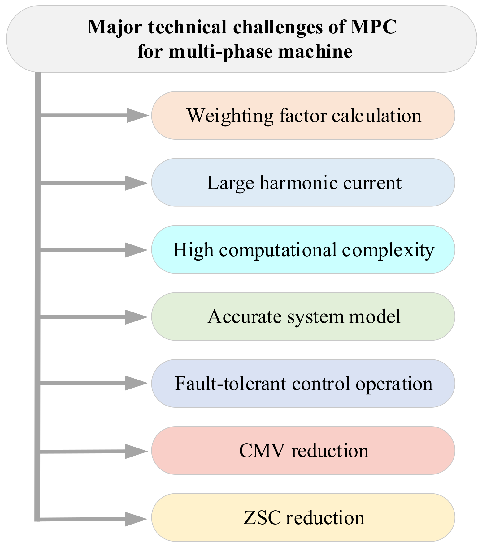
5. Future Trends of MPC for Multi-Phase Machines

Although MPC of multi-phase machines has made great progress in the past few years, there are still some open research topics that need to be further investigated.
In MPC methods for multi-phase machine, WF is needed to penalize the CF to obtain the desired control performance. However, WF affects the dynamic and steady-state performance of the machine, and the stability of the control system. Therefore, research on novel MPC methods independent of WF is a hot research topic.
In addition, previous fault diagnosis methods for multi-phase machines mainly focus on FOC and DTC schemes [183,184,185]. Although some researchers have proposed several MPC-based fault diagnosis methods for three-phase machines [186,187,188,189], the research on fault diagnosis of multi-phase machines by using MPC methods is still limited [190], which is of great significance to the development of MPC for multi-phase electric drives.
Moreover, model-free or parameter-free predictive control is independent of the machine model, which is a promising method to improve the parameter robustness of the MPC for multi-phase machines and reduces the dependence on the machine parameters.
Finally, artificial intelligence (AI) has brought a novel research direction to modern power electronics and microgrids [191,192]. It is hoped that AI can be applied in the driving, fault diagnosis, and fault-tolerant control for MPC of the multi-phase machine, and further promote the development of multi-phase electric drives toward a more intelligent direction.

6. Conclusions

Multi-phase electric drives require reliable and efficient control schemes to control multiple degrees of freedom simultaneously. Among various control strategies, MPC is a competitive technology to achieve this objective because of its inherent characteristic of multi-objective control. In the past decades, various types of research on MPC have been conducted for multi-phase electric drives, mainly in terms of weighting factor design, harmonic current suppression, computational complexity reduction, fault-tolerant operation, and CMW and ZSC suppression. In this paper, the research status of the MPC method for multi-phase electric drives is reviewed and analyzed. Firstly, the mathematical model of a multi-phase machine is derived, and then three basic MPC strategies are analyzed. Secondly, the latest and different solutions of MPC applications for the multi-phase machines are analyzed by presenting the influence of each challenge. Finally, the emerging technologies and future trends of MPC for multi-phase electric drives are discussed. It is foreseen that MPC, with its intuitive principle, fast dynamic response, and flexible and diverse expansion, will be the development trend of multi-phase electric drives. Moreover, novel weighting factors design, fault diagnosis methods, model-free or parameter-free predictive control, and AI technologies will be the future trend of MPC for multi-phase electric drives.

Author Contributions

Conceptualization, Z.X. and S.N.; methodology, Z.X. and Y.L.; software, Z.X. and H.L.; validation, Z.X., Y.L. and H.L.; formal analysis, Z.X. and X.L.; investigation, Z.X. and S.N.; resources, A.M.H.C. and S.N.; writing—original draft preparation, Z.X. and S.N.; writing—review and editing, A.M.H.C., Y.L. and X.L.; supervision, S.N. and X.L.; project administration, H.L.; funding acquisition, S.N. All authors have read and agreed to the published version of the manuscript.

Funding

This work was supported by the National Natural Science Foundation of China under Project 52077187 and in part by the Research Grant Council of the Hong Kong Government under Project PolyU 152143/18E and PolyU 152109/20E.

Data Availability Statement

Not applicable.

Conflicts of Interest

The authors declare no conflict of interest.

References

  1. Shao, L.; Hua, W.; Dai, N.; Tong, M.; Cheng, M. Mathematical modeling of a 12-phase flux-switching permanent-magnet machine for wind power generation. IEEE Trans. Ind. Electron. 2016, 63, 504–516. [Google Scholar] [CrossRef]
  2. Rodas, J. A brief survey of model predictive current control techniques for six-phase induction machines. In Proceedings of the 2021 IEEE CHILEAN Conference on Electrical, Electronics Engineering, Information and Communication Technologies (CHILECON), Valparaíso, Chile, 6–9 December 2021; pp. 1–6. [Google Scholar] [CrossRef]
  3. Zhou, H.; Zhou, C.; Tao, W.; Wang, J.; Liu, G. Virtual-stator-flux-based direct torque control of five-phase fault-tolerant permanent-magnet motor with open-circuit fault. IEEE Trans. Power Electron. 2020, 35, 5007–5017. [Google Scholar] [CrossRef]
  4. Barrero, F.; Duran, M.J. Recent advances in the design, modeling, and control of multiphase machines—Part I. IEEE Trans. Ind. Electron. 2016, 63, 449–458. [Google Scholar] [CrossRef]
  5. Duran, M.J.; Barrero, F. Recent advances in the design, modeling, and control of multiphase machines—Part II. IEEE Trans. Ind. Electron. 2016, 63, 459–468. [Google Scholar] [CrossRef]
  6. Berm, M.; Mart, C.; Gonz, I.; Dur, M.J.; Barrero, F. Predictive current control in electrical drives: An illustrated review with case examples using a five-phase induction motor drive with distributed windings. IET Electr. Power Appl. 2020, 14, 1291–1310. [Google Scholar]
  7. Cao, B.; Grainger, B.M.; Wang, X.; Zou, Y.; Reed, G.F.; Mao, Z.-H. Direct torque model predictive control of a five-phase permanent magnet synchronous motor. IEEE Trans. Power Electron. 2021, 36, 2346–2360. [Google Scholar] [CrossRef]
  8. Vazquez, S.; Rodriguez, J.; Rivera, M.; Franquelo, L.G.; Norambuena, M. Model predictive control for power converters and drives: Advances and trends. IEEE Trans. Ind. Electron. 2017, 64, 935–947. [Google Scholar] [CrossRef]
  9. Rodriguez, J.; Garcia, C.; Mora, A.; Flores-Bahamonde, F.; Acuna, P.; Novak, M.; Zhang, Y.; Tarisciotti, L.; Davari, S.A.; Zhang, Z.; et al. Latest advances of model predictive control in electrical drives—Part I: Basic concepts and advanced strategies. IEEE Trans. Power Electron. 2022, 37, 3927–3942. [Google Scholar] [CrossRef]
  10. Rodriguez, J.; Garcia, C.; Mora, A.; Davari, S.A.; Rodas, J.; Valencia, D.F.; Elmorshedy, M.; Wang, F.; Zuo, K.; Tarisciotti, L.; et al. Latest advances of model predictive control in electrical drives—Part II: Applications and benchmarking with classical control 4methods. IEEE Trans. Power Electron. 2022, 37, 5047–5061. [Google Scholar] [CrossRef]
  11. Li, X.; Xue, Z.; Zhang, L.; Hua, W. A low-complexity three-vectorbased model predictive torque control for spmsm. IEEE Trans. Power Electron. 2021, 36, 13002–13012. [Google Scholar] [CrossRef]
  12. Wang, Y.; Wang, X.; Xie, W.; Wang, F.; Dou, M.; Kennel, R.M.; Lorenz, R.D.; Gerling, D. Deadbeat model-predictive torque control with discrete space-vector modulation for pmsm drives. IEEE Trans. Ind. Electron. 2017, 64, 3537–3547. [Google Scholar] [CrossRef]
  13. Li, X.; Xue, Z.; Yan, X.; Zhang, L.; Ma, W.; Hua, W. Low-complexity multivector-based model predictive torque control for pmsm with voltage preselection. IEEE Trans. Power Electron. 2021, 36, 11726–11738. [Google Scholar] [CrossRef]
  14. Fretes, H.; Rodas, J.; Doval-Gandoy, J.; Gomez, V.; Gomez, N.; Novak, M.; Rodriguez, J.; Dragicevic, T. Pareto optimal weighting factor design of predictive current controller of a six-phase induction machine based on particle swarm optimization algorithm. IEEE J. Emerg. Sel. Top. Power Electron. 2022, 10, 207–219. [Google Scholar] [CrossRef]
  15. Levi, E. Multiphase electric machines for variable-speed applications. IEEE Trans. Ind. Electron. 2008, 55, 1893–1909. [Google Scholar] [CrossRef]
  16. Cervone, A.; Dordevic, O.; Brando, G. General approach for modeling and control of multiphase pmsm drives. IEEE Trans. Power Electron. 2021, 36, 10490–10503. [Google Scholar] [CrossRef]
  17. Zhao, Y.; Lipo, T. Space vector pwm control of dual three-phase induction machine using vector space decomposition. IEEE Trans. Ind. Appl. 1995, 31, 1100–1109. [Google Scholar] [CrossRef]
  18. Muduli, U.R.; Chikondra, B.; Behera, R.K. Space vector pwm based dtc scheme with reduced common mode voltage for five-phase induction motor drive. IEEE Trans. Power Electron. 2022, 37, 114–124. [Google Scholar] [CrossRef]
  19. Bhowate, A.; Aware, M.V.; Sharma, S. Speed sensor-less predictive torque control for five-phase induction motor drive using synthetic voltage vectors. IEEE J. Emerg. Sel. Top. Power Electron. 2021, 9, 2698–2709. [Google Scholar] [CrossRef]
  20. Tomlinson, M.; Mouton, H.T.; Kennel, R.; Stolze, P. A fixed switching frequency scheme for finite-control-set model predictive control—Concept and algorithm. IEEE Trans. Ind. Electron. 2016, 63, 7662–7670. [Google Scholar] [CrossRef]
  21. Liu, X.; Wang, J.; Gao, X.; Tian, W.; Zhou, L.; Rodriguez, J.; Kennel, R. Continuous control set predictive speed control of spmsm drives with short prediction horizon. IEEE Trans. Power Electron. 2022, 37, 10166–10177. [Google Scholar] [CrossRef]
  22. Norambuena, M.; Rodriguez, J.; Zhang, Z.; Wang, F.; Garcia, C.; Kennel, R. A very simple strategy for high-quality performance of ac machines using model predictive control. IEEE Trans. Power Electron. 2019, 34, 794–800. [Google Scholar] [CrossRef]
  23. Mart, C.; Arahal, M.R.; Barrero, F.; Duran, M.J. Five-phase induction motor rotor current observer for finite control set model predictive control of stator current. IEEE Trans. Ind. Electron. 2016, 63, 4527–4538. [Google Scholar] [CrossRef]
  24. Lim, C.S.; Levi, E.; Jones, M.; Rahim, N.A.; Hew, W.P. Fcs-mpc-based current control of a five-phase induction motor and its comparison with 6pi-pwm control. IEEE Trans. Ind. Electron. 2014, 61, 149–163. [Google Scholar] [CrossRef]
  25. Riveros, J.A.; Barrero, F.; Levi, E.; Duran, M.J.; Toral, S.; Jones, M. Variable-speed five-phase induction motor drive based on predictive torque control. IEEE Trans. Ind. Electron. 2013, 60, 2957–2968. [Google Scholar] [CrossRef]
  26. Mousa, H.H.H.; Youssef, A.-R.; Mohamed, E.E.M. Model predictive speed control of five-phase pmsg based variable speed wind generation system. In Proceedings of the 2018 Twentieth International Middle East Power Systems Conference (MEPCON), Cairo, Egypt, 18–20 December 2018; pp. 304–309. [Google Scholar] [CrossRef]
  27. Luo, Y.; Liu, C. A simplified model predictive control for a dual three-phase pmsm with reduced harmonic currents. IEEE Trans. Ind. Electron. 2018, 65, 9079–9089. [Google Scholar] [CrossRef]
  28. Yu, F.; Liu, X.; Zhu, Z.; Mao, J. An improved finite-control-set model predictive flux control for asymmetrical six-phase pmsms with a novel duty-cycle regulation strategy. IEEE Trans. Energy Convers. 2021, 36, 1289–1299. [Google Scholar] [CrossRef]
  29. Yang, Y.; Wen, H.; Fan, M.; He, L.; Xie, M.; Chen, R.; Norambuena, M.; Rodríguez, J. Multiple-voltage-vector model predictive control with reduced complexity for multilevel inverters. IEEE Trans. Transp. Electrif. 2020, 6, 105–117. [Google Scholar] [CrossRef]
  30. Zhang, X.; Hou, B. Double vectors model predictive torque control without weighting factor based on voltage tracking error. IEEE Trans. Power Electron. 2018, 33, 2368–2380. [Google Scholar] [CrossRef]
  31. Xue, C.; Song, W.; Feng, X. Finite control-set model predictive current control of five-phase permanent-magnet synchronous machine based on virtual voltage vectors. IET Electr. Power Appl. 2017, 11, 836–846. [Google Scholar] [CrossRef]
  32. Liu, S.; Liu, C. Virtual-vector-based robust predictive current control for dual three-phase pmsm. IEEE Trans. Ind. Electron. 2021, 68, 2048–2058. [Google Scholar] [CrossRef]
  33. Liu, X.; Jin, W.; Li, Z.; Hao, Z.; Kennel, R. Simplified predictive torque control of five phase permanent magnet motor with non-sinusoidal back-emf. In Proceedings of the IECON 2018—44th Annual Conference of the IEEE Industrial Electronics Society, Washington, DC, USA, 21–23 October 2018. [Google Scholar]
  34. Luo, Y.; Liu, C. Model predictive control for a six-phase pmsm motor with a reduced-dimension cost function. IEEE Trans. Ind. Electron. 2019, 67, 969–979. [Google Scholar] [CrossRef]
  35. Wang, W.; Song, Z.; Liu, Y.; Liu, C. Decoupled modulation scheme for harmonic current suppression in five-phase pmsm. IEEE Trans. Power Electron. 2022, 37, 8795–8799. [Google Scholar] [CrossRef]
  36. Wang, F.; Xie, H.; Chen, Q.; Davari, S.A.; Rodr, J.; Kennel, R. Parallel predictive torque control for induction machines without weighting factors. IEEE Trans. Power Electron. 2020, 35, 1779–1788. [Google Scholar] [CrossRef]
  37. Davari, S.A.; Norambuena, M.; Nekoukar, V.; Garcia, C.; Rodriguez, J. Even-handed sequential predictive torque and flux control. IEEE Trans. Ind. Electron. 2020, 67, 7334–7342. [Google Scholar] [CrossRef]
  38. Xiong, S.; Li, J. Cascade Model Predictive Current Control for Five-Phase Permanent Magnet Synchronous Motor. IEEE Access 2022, 10, 88812–88820. [Google Scholar] [CrossRef]
  39. Sun, Z.; Xu, S.; Ren, G.; Yao, C.; Ma, G. A cascaded band based model predictive current control for pmsm drives. IEEE Trans. Ind. Electron. 2022, 70, 3503–3514. [Google Scholar] [CrossRef]
  40. Musunuru, N.S.P.; Srirama, S. Cascaded predictive control of a single power supply-driven four-level open-end winding induction motor drive without weighting factors. IEEE J. Emerg. Sel. Top. Power Electron. 2021, 9, 2858–2867. [Google Scholar] [CrossRef]
  41. Dragičević, T.; Novak, M. Weighting factor design in model predictive control of power electronic converters: An artificial neural network approach. IEEE Trans. Ind. Electron. 2018, 66, 8870–8880. [Google Scholar] [CrossRef]
  42. Yao, C.; Sun, Z.; Xu, S.; Zhang, H.; Ren, G.; Ma, G. Optimal parameters design for model predictive control using an artificial neural network optimized by genetic algorithm. In Proceedings of the 2021 13th International Symposium on Linear Drives for Industry Applications (LDIA), Wuhan, China, 1–3 July 2021; pp. 1–6. [Google Scholar] [CrossRef]
  43. Wan, Y.; Dragicevic, T.; Mijatovic, N.; Li, C.; Rodriguez, J. Reinforcement learning based weighting factor design of model predictive control for power electronic converters. In Proceedings of the 2021 IEEE International Conference on Predictive Control of Electrical Drives and Power Electronics (PRECEDE), Jinan, China, 20–22 November 2021; pp. 738–743. [Google Scholar] [CrossRef]
  44. Yao, C.; Sun, Z.; Xu, S.; Zhang, H.; Ren, G.; Ma, G. ANN optimization of weighting factors using genetic algorithm for model predictive control of PMSM drives. IEEE Trans. Ind. Appl. 2022, 58, 7346–7362. [Google Scholar] [CrossRef]
  45. Bhowate, A.; Aware, M.V.; Sharma, S. Predictive torque control algorithm for a five-phase induction motor drive for reduced torque ripple with switching frequency control. IEEE Trans. Power Electron. 2020, 35, 7282–7294. [Google Scholar] [CrossRef]
  46. Xu, Y.; Zheng, B.; Wang, G.; Yan, H.; Zou, J. Current harmonic suppression in dual three-phase permanent magnet synchronous machine with extended state observer. IEEE Trans. Power Electron. 2020, 35, 12166–12180. [Google Scholar] [CrossRef]
  47. Gon, P.F.C.; Cruz, S.M.A.; Mendes, A.M.S. Fixed and variable amplitude virtual vectors for model predictive control of six-phase pmsms with single neutral configuration. In Proceedings of the 2019 IEEE International Conference on Industrial Technology (ICIT), Melbourne, VIC, Australia, 13–15 February 2019; pp. 267–273. [Google Scholar] [CrossRef]
  48. Du, Y.; Ji, J.; Zhao, W.; Tao, T.; Xu, D. Self-adapted model predictive current control for five-phase open-end winding pmsm with reduced switching loss. IEEE Trans. Power Electron. 2022, 37, 11007–11018. [Google Scholar] [CrossRef]
  49. Ren, Y.; Zhu, Z.Q. Enhancement of steady-state performance in directtorque-controlled dual three-phase permanent-magnet synchronous machine drives with modified switching table. IEEE Trans. Ind. Electron. 2015, 62, 3338–3350. [Google Scholar] [CrossRef]
  50. Yang, G.; Yang, J.; Li, S.; Wang, Y.; Hussain, H.; Deng, R.; Yan, L. A sequential direct torque control scheme for seven-phase induction machines based on virtual voltage vectors. IEEE Trans. Ind. Appl. 2021, 57, 3722–3734. [Google Scholar] [CrossRef]
  51. Luo, Y.; Liu, C. A flux constrained predictive control for a six-phase pmsm motor with lower complexity. IEEE Trans. Ind. Electron. 2019, 66, 5081–5093. [Google Scholar] [CrossRef]
  52. Luo, Y.; Liu, C. Multi-vector-based model predictive torque control for a six-phase pmsm motor with fixed switching frequency. IEEE Trans. Energy Convers. 2019, 34, 1369–1379. [Google Scholar] [CrossRef]
  53. Aciego, J.J.; Gonz, I.; Duran, M.J. Model predictive control of six-phase induction motor drives using two virtual voltage vectors. IEEE J. Emerg. Sel. Top. Power Electron. 2019, 7, 321–330. [Google Scholar] [CrossRef]
  54. Goncalves, P.; Cruz, S.; Mendes, A. Bi-subspace predictive current control of six-phase pmsm drives based on virtual vectors with optimal amplitude. Electr. Power Appl. IET 2019, 13, 1672–1683. [Google Scholar] [CrossRef]
  55. Aciego, J.J.; Prieto, I.G.; Duran, M.J.; Bermudez, M.; SalasBiedma, P. Model predictive control based on dynamic voltage vectors for six-phase induction machines. IEEE J. Emerg. Sel. Top. Power Electron. 2021, 9, 2710–2722. [Google Scholar] [CrossRef]
  56. González-Prieto, A.; González-Prieto, I.; Duran, M.J. Smart voltage vectors for model predictive control of six-phase electric drives. IEEE Trans. Ind. Electron. 2021, 68, 9024–9035. [Google Scholar] [CrossRef]
  57. Gonzalez, O.; Ayala, M.; Romero, C.; Delorme, L.; Rodas, J.; Gregor, R.; Gonzalez-Prieto, I.; Durán, M.J. Model predictive current control of sixphase induction motor drives using virtual vectors and space vector modulation. IEEE Trans. Power Electron. 2022, 37, 7617–7628. [Google Scholar] [CrossRef]
  58. Saeed, M.S.R.; Song, W.; Huang, L.; Yu, B. Double-vector-based finite control set model predictive control for five-phase pmsms with high tracking accuracy and dc-link voltage utilization. IEEE Trans. Power Electron. 2022, 37, 15234–15244. [Google Scholar] [CrossRef]
  59. González-Prieto, A.; González-Prieto, I.; Duran, M.J.; Aciego, J.J.; SalasBiedma, P. Current harmonic mitigation using a multi-vector solution for mpc in six-phase electric drives. IEEE Access 2021, 9, 117761–117771. [Google Scholar] [CrossRef]
  60. Wang, W.; Liu, C.; Liu, S.; Zhao, H. Model predictive torque control for dual three-phase pmsms with simplified deadbeat solution and discrete space-vector modulation. IEEE Trans. Energy Convers. 2021, 36, 1491–1499. [Google Scholar] [CrossRef]
  61. Gonzalez, O.; Ayala, M.; Doval-Gandoy, J.; Rodas, J.; Rivera, M. Predictivefixed switching current control strategy applied to six-phase induction machine. Energies 2019, 12, 2294. [Google Scholar] [CrossRef]
  62. Ayala, M.; Doval-Gandoy, J.; Gonzalez, O.; Rodas, J.; Gregor, R.; Rivera, M. Experimental stability study of modulated model predictive current controllers applied to six-phase induction motor drives. IEEE Trans. Power Electron. 2021, 36, 13275–13284. [Google Scholar] [CrossRef]
  63. Ayala, M.; Doval-Gandoy, J.; Rodas, J.; Gonzalez, O.; Gregor, R.; Rivera, M. A novel modulated model predictive control applied to six-phase induction motor drives. IEEE Trans. Ind. Electron. 2021, 68, 3672–3682. [Google Scholar] [CrossRef]
  64. Gonzalez-Prieto, A.; Martin, C.; Gonzalez-Prieto, I.; Duran, M.J.; Carrillo-Ríos, J.; Aciego, J.J. Hybrid multivector fcs–mpc for six-phase electric drives. IEEE Trans. Power Electron. 2022, 37, 8988–8999. [Google Scholar] [CrossRef]
  65. Liu, S.; Liu, C. Direct harmonic current control scheme for dual three-phase pmsm drive system. IEEE Trans. Power Electron. 2021, 36, 11647–11657. [Google Scholar] [CrossRef]
  66. Ye, D.; Li, J.; Qu, R.; Lu, H.; Lu, Y. Finite set model predictive mtpa control with vsd method for asymmetric six-phase pmsm. In Proceedings of the 2017 IEEE International Electric Machines and Drives Conference (IEMDC), Miami, FL, USA, 21–24 May 2017; pp. 1–7. [Google Scholar] [CrossRef]
  67. Wang, W.; Fan, Y.; Chen, S.; Zhang, Q. Finite control set model predictive current control of a five-phase PMSM with virtual voltage vectors and adaptive control set. CES Trans. Electr. Mach. Syst. 2018, 2, 136–141. [Google Scholar] [CrossRef]
  68. Yu, B.; Song, W.; Yang, K.; Guo, Y.; Saeed, M.S.R. A computationally efficient finite control set model predictive control for multiphase pmsm drives. IEEE Trans. Ind. Electron. 2022, 69, 12066–12076. [Google Scholar] [CrossRef]
  69. Luo, Y.; Liu, C. Elimination of harmonic currents using a reference voltage vector based-model predictive control for a six-phase pmsm motor. IEEE Trans. Power Electron. 2019, 34, 6960–6972. [Google Scholar] [CrossRef]
  70. Wang, X.; Wang, Z.; Xu, Z.; Wang, W.; Wang, B.; Zou, Z. Deadbeat predictive current control-based fault-tolerant scheme for dual three-phase pmsm drives. IEEE J. Emerg. Sel. Top. Power Electron. 2021, 9, 1591–1604. [Google Scholar] [CrossRef]
  71. Huang, W.; Hua, W.; Yin, F.; Yu, F.; Qi, J. Model predictive thrust force control of a linear flux-switching permanent magnet machine with voltage vectors selection and synthesis. IEEE Trans. Ind. Electron. 2019, 66, 4956–4967. [Google Scholar] [CrossRef]
  72. Hua, W.; Chen, F.; Huang, W.; Zhang, G.; Wang, W.; Xia, W. Multivectorbased model predictive control with geometric solution of a five-phase flux-switching permanent magnet motor. IEEE Trans. Ind. Trial Electron. 2020, 67, 10035–10045. [Google Scholar] [CrossRef]
  73. Tao, T.; Zhao, W.; He, Y.; Zhu, J.; Tan, H.; Xue, R. Multivector predictive current control for five-phase pm motor by using hybrid duty modulation technology. IEEE Trans. Transp. Electrif. 2020, 6, 1603–1612. [Google Scholar] [CrossRef]
  74. Lin, X.; Huang, W.; Jiang, W.; Zhao, Y.; Zhu, S. Deadbeat direct torque and flux control for permanent magnet synchronous motor based on stator flux oriented. IEEE Trans. Power Electron. 2020, 35, 5078–5092. [Google Scholar] [CrossRef]
  75. Wang, W.; Liu, C.; Zhao, H.; Song, Z. Improved deadbeat-direct torque and flux control for pmsm with less computation and enhanced robustness. IEEE Trans. Ind. Electron. 2022, 70, 2254–2263. [Google Scholar] [CrossRef]
  76. Luo, Y.; Liu, C. Model predictive torque control of an open-end winding pmsm with reduced computation time. In Proceedings of the 2017 20th International Conference on Electrical Machines and Systems (ICEMS), Sydney, NSW, Australia, 11–14 August 2017; pp. 1–6. [Google Scholar] [CrossRef]
  77. Zhang, Z.; Wang, Z.; Wei, X.; Liang, Z.; Kennel, R.; Rodriguez, J. Spacevector-optimized predictive control for dual three-phase pmsm with quick current response. IEEE Trans. Power Electron. 2022, 37, 4453–4462. [Google Scholar] [CrossRef]
  78. Luo, Y.; Liu, C. Model predictive control for a six-phase pmsm with high robustness against weighting factor variation. IEEE Trans. Ind. Appl. 2019, 55, 2781–2791. [Google Scholar] [CrossRef]
  79. Zhou, Y.; Chen, G. Predictive dtc strategy with fault-tolerant function for six-phase and three-phase pmsm series-connected drive system. IEEE Trans. Ind. Electron. 2018, 65, 9101–9112. [Google Scholar] [CrossRef]
  80. Luo, Y.; Zhang, X.; Niu, S. A hybrid two-stage control solution for sixphase pmsm motor with improved performance. IEEE J. Emerg. Sel. Top. Power Electron. 2022, 10, 5435–5445. [Google Scholar] [CrossRef]
  81. Li, T.; Ma, R. An improved deadbeat predictive current control for five phase pmsm. In Proceedings of the 2021 IEEE International Conference on Predictive Control of Electrical Drives and Power Electronics (PRECEDE), Jinan, China, 20–22 November 2021; pp. 562–569. [Google Scholar] [CrossRef]
  82. Yan, L.; Wang, F.; Tao, P.; Zuo, K. Robust predictive torque control of permanent magnet synchronous machine using discrete hybrid prediction model. IEEE Trans. Energy Convers. 2020, 35, 2240–2248. [Google Scholar] [CrossRef]
  83. Zhang, X.; Wang, Z. Simple robust model predictive current control for pmsm drives without flux linkage parameter. IEEE Trans. Ind. Electron. 2022, 70, 3515–3524. [Google Scholar] [CrossRef]
  84. Yuan, X.; Zhang, S.; Zhang, C. Improved model predictive current control for spmsm drives with parameter mismatch. IEEE Trans. Ind. Electron. 2020, 67, 852–862. [Google Scholar] [CrossRef]
  85. Abdelrahem, M.; Hackl, C.M.; Kennel, R.; Rodriguez, J. Efficient directmodel predictive control with discrete-time integral action for pmsgs. IEEE Trans. Energy Convers. 2019, 34, 1063–1072. [Google Scholar] [CrossRef]
  86. Fu, R. Robust predictive current control of dual three-phase pmsm using prediction error correction. In Proceedings of the 2021 IEEE International Conference 14on Predictive Control of Electrical Drives and Power Electronics (PRECEDE), Jinan, China, 20–22 November 2021; pp. 576–581. [Google Scholar] [CrossRef]
  87. Yao, X.; Zhang, F.; Wang, J.; Huang, S.; Wang, Y.; Ma, H. Improved predictive torque control of pmsm considering inductance parameter mismatch. In Proceedings of the 2021 IEEE International Electric Machines Drives Conference (IEMDC), Hartford, CT, USA, 17–20 May 2021; pp. 1–6. [Google Scholar] [CrossRef]
  88. Mohamed, Y.A.-R.I.; El-Saadany, E.F. An improved deadbeat current control scheme with a novel adaptive self-tuning load model for a three-phase pwm voltage-source inverter. IEEE Trans. Ind. Electron. 2007, 54, 747–759. [Google Scholar] [CrossRef]
  89. Mwasilu, F.; Jung, J.-W. Enhanced fault-tolerant control of interior pmsms based on an adaptive ekf for ev traction applications. IEEE Trans. Power Electron. 2016, 31, 5746–5758. [Google Scholar] [CrossRef]
  90. Gao, S.; Dong, H.; Ning, B.; Tang, T.; Li, Y. Nonlinear mapping-based feedback technique of dynamic surface control for the chaotic pmsm using neural approximation and parameter identification. IET Control. Theory Appl. 2018, 12, 819–827. [Google Scholar] [CrossRef]
  91. Jabbour, N.; Mademlis, C. Online parameters estimation and autotuning of a discrete-time model predictive speed controller for induction motor drives. IEEE Trans. Power Electron. 2019, 34, 1548–1559. [Google Scholar] [CrossRef]
  92. Liu, Z.-H.; Jing, L.; Li, X.-H.; Zhang, Y.-J. Cooperative particle swarm optimization with ics and its application to parameter identification of pmsm. In Proceedings of the 2012 7th IEEE Conference on Industrial Electronics and Applications (ICIEA), Singapore, 18–20 July 2012; pp. 1303–1308. [Google Scholar] [CrossRef]
  93. Sun, X.; Cao, J.; Lei, G.; Guo, Y.; Zhu, J. A robust deadbeat predictive controller with delay compensation based on composite sliding-mode observer for pmsms. IEEE Trans. Power Electron. 2021, 36, 10742–10752. [Google Scholar] [CrossRef]
  94. Perera, A.; Nilsen, R. A.; Nilsen, R. A method based on prediction-error-gradients to estimate pmsm parameters online. In IEEE IAS Annual Meeting 2020; IEEE: Piscataway, NJ, USA, 2020. [Google Scholar]
  95. Mehreganfar, M.; Saeedinia, M.H.; Davari, S.A.; Garcia, C.; Rodriguez, J. Sensorless predictive control of afe rectifier with robust adaptive inductance estimation. IEEE Trans. Ind. Inform. 2019, 15, 3420–3431. [Google Scholar] [CrossRef]
  96. Saeed, M.S.R.; Song, W.; Yu, B. Robustness improvement of deadbeat model predictive control for five-phase pmsm drives. In Proceedings of the 2020 15th IEEE Conference on Industrial Electronics and Applications (ICIEA), Kristiansand, Norway, 9–13 November 2020; pp. 1336–1341. [Google Scholar] [CrossRef]
  97. Chen, Y.; Liu, C.; Liu, S.; Song, Z. A new cascaded adaptive deadbeat control method for pmsm drive. IEEE Trans. Ind. Electron. 2022, 70, 3384–3393. [Google Scholar] [CrossRef]
  98. Perera, A.; Nilsen, R. Gauss-newton: A prediction-error-gradient based algorithm to track PMSM parameters online. In Proceedings of the 2020 IEEE International Conference on Power Electronics, Drives and Energy Systems (PEDES), Jaipur, India, 16–19 December 2020; pp. 1–8. [Google Scholar] [CrossRef]
  99. Brosch, A.; Hanke, S.; Wallscheid, O.; Bocker, J. Data-driven recursive least squares estimation for model predictive current control of permanent magnet synchronous motors. IEEE Trans. Power Electron. 2021, 36, 2179–2190. [Google Scholar] [CrossRef]
  100. Zhang, X.; Zhao, Z.; Cheng, Y.; Wang, Y. Robust model predictive current control based on inductance and flux linkage extraction algorithm. IEEE Trans. Veh. Technol. 2020, 69, 14893–14902. [Google Scholar] [CrossRef]
  101. Yuan, X.; Zhang, S.; Zhang, C.; Galassini, A.; Degano, M. Improved model predictive current control for spmsm drives using current update mechanism. IEEE Trans. Ind. Electron. 2020, 68, 1938–1948. [Google Scholar] [CrossRef]
  102. Li, X.; Zhang, S.; Cui, X.; Wang, Y.; Zhang, C.; Li, Z.; Zhou, Y. Novel deadbeat predictive current control for pmsm with parameter updating scheme. IEEE J. Emerg. Sel. Top. Power Electron. 2022, 10, 2065–2074. [Google Scholar] [CrossRef]
  103. Yan, L.; Wang, F.; Dou, M.; Zhang, Z.; Kennel, R.; Rodríguez, J. Active disturbance-rejection-based speed control in model predictive control for induction machines. IEEE Trans. Ind. Electron. 2020, 67, 2574–2584. [Google Scholar] [CrossRef]
  104. Wang, F.; Wang, J.; Kennel, R.M.; Rodríguez, J. Fast speed control of ac machines without the proportional-integral controller: Using an extended high-gain state observer. IEEE Trans. Power Electron. 2019, 34, 9006–9015. [Google Scholar] [CrossRef]
  105. Yan, L.; Dou, M.; Hua, Z.; Zhang, H.; Yang, J. Robustness improvement of fcs-mptc for induction machine drives using disturbance feedforward technique. IEEE Trans. Power Electron. 2019, 34, 2874–2886. [Google Scholar] [CrossRef]
  106. Wang, J.; Wang, F.; Wang, G.; Li, S.; Yu, L. Generalized proportional integral observer based robust finite control set predictive current control for induction motor systems with time-varying disturbances. IEEE Trans. Ind. Inform. 2018, 14, 4159–4168. [Google Scholar] [CrossRef]
  107. Xiong, C.; Xu, H.; Guan, T.; Zhou, P. A constant switching frequency multiple-vector-based model predictive current control of five-phase pmsm with nonsinusoidal back emf. IEEE Trans. Ind. Electron. 2020, 67, 1695–1707. [Google Scholar] [CrossRef]
  108. Gon, P.F.C.; Cruz, S.M.A.; Mendes, A.M.S. Suppression of steadystate errors in predictive current control of six-phase pmsm drives. In Proceedings of the 2020 International Conference on Smart Energy Systems and Technologies (SEST), Istanbul, Turkey, 7–9 September 2020; pp. 1–6. [Google Scholar] [CrossRef]
  109. Bermudez, M.; Arahal, M.R.; Duran, M.J.; Gonzalez-Prieto, I. Model predictive control of six-phase electric drives including arx disturbance estimator. IEEE Trans. Ind. Electron. 2021, 68, 81–91. [Google Scholar] [CrossRef]
  110. An, X.; Liu, G.; Chen, Q.; Zhao, W.; Song, X. Robust predictive current control for fault-tolerant operation of five-phase pm motors based on online stator inductance identification. IEEE Trans. Power Electron. 2021, 36, 13162–13175. [Google Scholar] [CrossRef]
  111. Yu, K.; Wang, Z.; Hua, W.; Cheng, M. Robust cascaded deadbeat predictive control for dual three-phase variable-flux pmsm considering intrinsic delay in speed loop. IEEE Trans. Ind. Electron. 2022, 69, 12107–12118. [Google Scholar] [CrossRef]
  112. Gon, P.F.; Cruz, S.M.; Mendes, A.M.S. Disturbance observer based predictive current control of six-phase permanent magnet synchronous machines for the mitigation of steady-state errors and current harmonics. IEEE Trans. Ind. Electron. 2022, 69, 130–140. [Google Scholar] [CrossRef]
  113. Lin, C.-K.; Liu, T.-H.; Yu, J.-t.; Fu, L.-C.; Hsiao, C.-F. Model-free predictive current control for interior permanent-magnet synchronous motor drives based on current difference detection technique. IEEE Trans. Ind. Electron. 2014, 61, 667–681. [Google Scholar] [CrossRef]
  114. Lin, C.-K.; Yu, J.-T.; Lai, Y.-S.; Yu, H.-C. Improved model-free predictive current control for synchronous reluctance motor drives. IEEE Trans. Ind. Electron. 2016, 63, 3942–3953. [Google Scholar] [CrossRef]
  115. Wang, P.; Yuan, X.; Zhang, C. An improved model free predictive current control for pmsm with current prediction error variations. IEEE Access 2022, 10, 54537–54548. [Google Scholar] [CrossRef]
  116. Carlet, P.G.; Tinazzi, F.; Bolognani, S.; Zigliotto, M. An effective modelfree predictive current control for synchronous reluctance motor drives. IEEE Trans. Ind. Appl. 2019, 55, 3781–3790. [Google Scholar] [CrossRef]
  117. Yu, F.; Zhou, C.; Liu, X.; Zhu, C. Model-free predictive current control for three-level inverter-fed ipmsm with an improved current difference updating technique. IEEE Trans. Energy Convers. 2021, 36, 3334–3343. [Google Scholar] [CrossRef]
  118. Zhang, Y.; Jin, J.; Huang, L. Model-free predictive current control of pmsm drives based on extended state observer using ultralocal model. IEEE Trans. Ind. Electron. 2021, 68, 993–1003. [Google Scholar] [CrossRef]
  119. Zhou, Y.; Li, H.; Yao, H. Model-free control of surface mounted pmsm drive system. In Proceedings of the 2016 IEEE International Conference on Industrial Technology (ICIT), Taipei, Taiwan, 14–17 March 2016; pp. 175–180. [Google Scholar] [CrossRef]
  120. Zhou, Y.; Li, H.; Zhang, H. Model-free deadbeat predictive current control of a surface-mounted permanent magnet synchronous motor drive system. J. Power Electron. 2018, 18, 103–115. [Google Scholar]
  121. Agoro, S.; Husain, I. Model-free predictive current and disturbance rejection control of dual three-phase pmsm drives using optimal virtual vector modulation. IEEE J. Emerg. Sel. Top. Power Electron. 2022. [Google Scholar] [CrossRef]
  122. Jin, N.; Chen, M.; Guo, L.; Li, Y.; Chen, Y. Double-vector model-free predictive control method for voltage source inverter with visualization analysis. IEEE Trans. Ind. Electron. 2022, 69, 10066–10078. [Google Scholar] [CrossRef]
  123. Norambuena, M.; Lezana, P.; Rodriguez, J. A method to eliminate steadystate error of model predictive control in power electronics. IEEE J. Emerg. Sel. Top. Power Electron. 2019, 7, 2525–2530. [Google Scholar] [CrossRef]
  124. Liu, X.; Zhou, L.; Wang, J.; Gao, X.; Li, Z.; Zhang, Z. Robust predictive current control of permanent-magnet synchronous motors with newly designed cost function. IEEE Trans. Power Electron. 2020, 35, 10778–10788. [Google Scholar] [CrossRef]
  125. Siami, M.; Khaburi, D.A.; Abbaszadeh, A.; Rodríguez, J. Robustness improvement of predictive current control using prediction error correction for permanent-magnet synchronous machines. IEEE Trans. Ind. Electron. 2016, 63, 3458–3466. [Google Scholar] [CrossRef]
  126. Li, Y.; Li, Y.; Wang, Q. Robust predictive current control with parallel compensation terms against multi-parameter mismatches for pmsms. IEEE Trans. Energy Convers. 2020, 35, 2222–2230. [Google Scholar] [CrossRef]
  127. Fu, R. Robust model predictive flux control of pmsm drive using a compensated stator flux predictor. IEEE Access 2021, 9, 136736–136743. [Google Scholar] [CrossRef]
  128. Wang, F.; Zuo, K.; Tao, P.; Rodríguez, J. High performance model predictive control for pmsm by using stator current mathematical model self regulation technique. IEEE Trans. Power Electron. 2020, 35, 13652–13662. [Google Scholar] [CrossRef]
  129. He, C.; Hu, J.; Li, Y. Robust predictive current control for pmsm drives with parameter mismatch. In Proceedings of the 2021 IEEE International Conference on Predictive Control of Electrical Drives and Power Electronics (PRECEDE), Jinan, China, 20–22 November 2021; pp. 542–546. [Google Scholar] [CrossRef]
  130. Xu, C.; Han, Z.; Lu, S. Deadbeat predictive current control for permanent magnet synchronous machines with closed-form error compensation. IEEE Trans. Power Electron. 2020, 35, 5018–5030. [Google Scholar] [CrossRef]
  131. Dai, S.; Wang, J.; Sun, Z.; Chong, E. Model inaccuracy analysis and compensation of stationary frame-based deadbeat predictive current control for high-speed pmsm drives. IEEE Trans. Transp. Electrif. 2022, 8, 2654–2666. [Google Scholar] [CrossRef]
  132. Lu, H.; Li, J.; Qu, R.; Ye, D.; Lu, Y. Fault-tolerant predictive control of six-phase PMSM drives based on pulse-width modulation. IEEE Trans. Ind. Electron. 2019, 66, 4992–5003. [Google Scholar] [CrossRef]
  133. Liu, G.; Song, C.; Chen, Q. Fcs-mpc-based fault-tolerant control of fivephase ipmsm for mtpa operation. IEEE Trans. Power Electron. 2020, 35, 2882–2894. [Google Scholar] [CrossRef]
  134. Wang, X.; Liu, G.; Chen, Q.; Farahat, A.; Song, X. Multivectors model predictive control with voltage error tracking for five-phase PMSM short-circuit fault-tolerant operation. IEEE Trans. Transp. Electrif. 2022, 8, 675–687. [Google Scholar] [CrossRef]
  135. Lu, H.; Li, J.; Qu, R.; Ye, D.; Xiao, L. Reduction of unbalanced axial magnetic force in postfault operation of a novel six-phase double-stator axialflux pm machine using model predictive control. IEEE Trans. Ind. Appl. 2017, 53, 5461–5469. [Google Scholar] [CrossRef]
  136. Huang, W.; Hua, W.; Fan, Q. Performance analysis and comparison of two fault-tolerant model predictive control methods for five-phase pmsm drives. CES Trans. Electr. Mach. Syst. 2021, 5, 311–320. [Google Scholar] [CrossRef]
  137. Guzman, H.; Duran, M.J.; Barrero, F.; Bogado, B.; Toral, S. Speed control of five-phase induction motors with integrated open-phase fault operation using model-based predictive current control techniques. IEEE Trans. Ind. Electron. 2014, 61, 4474–4484. [Google Scholar] [CrossRef]
  138. Guzman, H.; Duran, M.J.; Barrero, F.; Zarri, L.; Bogado, B.; Prieto, I.G.; Arahal, M.R. Comparative study of predictive and resonant controllers in fault-tolerant five-phase induction motor drives. IEEE Trans. Ind. Electron. 2016, 63, 606–617. [Google Scholar] [CrossRef]
  139. Huang, W.; Hua, W.; Chen, F.; Yin, F.; Qi, J. Model predictive current control of open-circuit fault-tolerant five-phase flux-switching permanent magnet motor drives. IEEE J. Emerg. Sel. Top. Power Electron. 2018, 6, 1840–1849. [Google Scholar] [CrossRef]
  140. Huang, W.; Hua, W.; Chen, F.; Hu, M.; Zhu, J. Model predictive torque control with svm for five-phase pmsm under open-circuit fault condition. IEEE Trans. Power Electron. 2020, 35, 5531–5540. [Google Scholar] [CrossRef]
  141. Huang, W.; Hua, W.; Chen, F.; Qi, J.; Zhu, J. Performance improvement of model predictive current control of fault-tolerant five-phase flux-switching permanent magnet motor drive. IEEE Trans. Ind. Appl. 2019, 55, 6001–6010. [Google Scholar] [CrossRef]
  142. Huang, W.; Hua, W.; Chen, F.; Zhu, J. Enhanced model predictive torque control of fault-tolerant five-phase permanent magnet synchronous motor with harmonic restraint and voltage preselection. IEEE Trans. Ind. Electron. 2020, 67, 6259–6269. [Google Scholar] [CrossRef]
  143. Tao, T.; Zhao, W.; Du, Y.; Cheng, Y.; Zhu, J. Simplified fault-tolerant model predictive control for a five-phase permanent-magnet motor with reduced computation burden. IEEE Trans. Power Electron. 2020, 35, 3850–3858. [Google Scholar] [CrossRef]
  144. Wang, H.; Zhao, W.; Tang, H.; Tao, T.; Saeed, S. Improved fault-tolerant model predictive torque control of five-phase pmsm by using deadbeat solution. IEEE Trans. Energy Convers. 2022, 37, 210–219. [Google Scholar] [CrossRef]
  145. Tao, T.; Zhao, W.; He, Y.; Cheng, Y.; Saeed, S.; Zhu, J. Enhanced faulttolerant model predictive current control for a five-phase pm motor with continued modulation. IEEE Trans. Power Electron. 2021, 36, 3236–3246. [Google Scholar] [CrossRef]
  146. Saeed, S.; Zhao, W.; Wang, H.; Tao, T.; Khan, F. Fault-tolerant deadbeat model predictive current control for a five-phase pmsm with improved svpwm. Chin. J. Electr. Eng. 2021, 7, 111–123. [Google Scholar] [CrossRef]
  147. Luo, Y.; Liu, C. Pre- and post-fault tolerant operation of a six-phase pmsm motor using fcs-mpc without controller reconfiguration. IEEE Trans. Veh. Technol. 2019, 68, 254–263. [Google Scholar] [CrossRef]
  148. González-Prieto, I.; Durán, M.J.; Bermúdez, M.; Barrero, F.; Martín, C. Assessment of virtual-voltage-based model predictive controllers in sixphase drives under open-phase faults. IEEE J. Emerg. Sel. Top. Power Electron. 2020, 8, 2634–2644. [Google Scholar] [CrossRef]
  149. Sun, X.; Li, T.; Tian, X.; Zhu, J. Fault-tolerant operation of a six-phase permanent magnet synchronous hub motor based on model predictive current control with virtual voltage vectors. IEEE Trans. Energy Convers. 2022, 37, 337–346. [Google Scholar] [CrossRef]
  150. Bhowate, A.; Aware, M.; Sharma, S.; Tatte, Y. Predictive torque control for five phase induction motor drive with common mode voltage reduction. In Proceedings of the 2018 International Power Electronics Conference (IPEC-Niigata 2018-ECCE Asia), Niigata, Japan, 20–24 May 2018; pp. 1730–1735. [Google Scholar] [CrossRef]
  151. Duran, M.J.; Riveros, J.A.; Barrero, F.; Guzman, H.; Prieto, J. Reduction of common-mode voltage in five-phase induction motor drives using predictive control techniques. IEEE Trans. Ind. Appl. 2012, 48, 2059–2067. [Google Scholar] [CrossRef]
  152. Dabour, S.M.; Abdel-Khalik, A.S.; Ahmed, S.; Massoud, A. Model predictive control for common-mode voltage reduction and third-harmonic current injection techniques with five-phase inverters. In Proceedings of the 2017 Nineteenth International Middle East Power Systems Conference (MEPCON), Cairo, Egypt, 19–21 December 2017; pp. 1310–1315. [Google Scholar] [CrossRef]
  153. Iqbal, A.; Alammari, R.; Mosa, M.; Abu-Rub, H. Finite set model predictive current control with reduced and constant common mode voltage for a five-phase voltage source inverter. In Proceedings of the 2014 IEEE 23rd International Symposium on Industrial Electronics (ISIE), Istanbul, Turkey, 1–4 June 2014; pp. 479–484. [Google Scholar] [CrossRef]
  154. Bhowate, A.; Aware, M.V.; Sharma, S. Predictive torque control of five-phase induction motor drive using successive cost functions for cmv elimination. IEEE Trans. Power Electron. 2021, 36, 14133–14141. [Google Scholar] [CrossRef]
  155. Yu, B.; Song, W.; Guo, Y.; Li, J.; Saeed, M.S.R. Virtual voltage vector-based model predictive current control for five-phase VSIs with common-mode voltage reduction. IEEE Trans. Transp. Electrif. 2021, 7, 706–717. [Google Scholar] [CrossRef]
  156. Vu, H.-C.; Lee, H.-H. Model-predictive current control scheme for sevenphase voltage-source inverter with reduced common-mode voltage and current harmonics. IEEE J. Emerg. Sel. Top. Power Electron. 2021, 9, 3610–3621. [Google Scholar] [CrossRef]
  157. Yu, B.; Song, W.; Li, J.; Li, B.; Saeed, M.S.R. Improved finite control set model predictive current control for five-phase vsis. IEEE Trans. Power Electron. 2021, 36, 7038–7048. [Google Scholar] [CrossRef]
  158. Yu, B.; Song, W.; Guo, Y.; Saeed, M.S.R. A finite control set model predictive control for five-phase pmsms with improved dc-link utilization. IEEE Trans. Power Electron. 2022, 37, 3297–3307. [Google Scholar] [CrossRef]
  159. Lai, Y.-S.; Shyu, F.-S. Optimal common-mode voltage reduction pwm technique for inverter control with consideration of the dead-time effects-part i: Basic development. IEEE Trans. Ind. Appl. 2004, 40, 1605–1612. [Google Scholar] [CrossRef]
  160. Kwak, S.; Mun, S.-K. Model predictive control methods to reduce common- mode voltage for three-phase voltage source inverters. IEEE Trans. Power Electron. 2015, 30, 5019–5035. [Google Scholar] [CrossRef]
  161. Kwak, S.; Mun, S. Common-mode voltage mitigation with a predictive control method considering dead time effects of three-phase voltage source inverters. Power Electron. IET 2014, 8, 1690–1700. [Google Scholar] [CrossRef]
  162. Guo, L.; Jin, N.; Gan, C.; Xu, L.; Wang, Q. An improved model predictive control strategy to reduce common-mode voltage for two-level voltage source inverters considering dead-time effects. IEEE Trans. Ind. Electron. 2019, 66, 3561–3572. [Google Scholar] [CrossRef]
  163. Guo, L.; Jin, N.; Gan, C.; Luo, K. Hybrid voltage vector preselection-based model predictive control for two-level voltage source inverters to reduce the common-mode voltage. IEEE Trans. Ind. Electron. 2020, 67, 4680–4691. [Google Scholar] [CrossRef]
  164. Wang, H.; Zheng, X.; Yuan, X.; Wu, X. Low-complexity model-predictive control for a nine-phase open-end winding pmsm with dead-time compensation. IEEE Trans. Power Electron. 2022, 37, 8895–8908. [Google Scholar] [CrossRef]
  165. Zhu, B.; Rajashekara, K.; Kubo, H. Predictive torque control with zero-sequence current suppression for open-end winding induction machine. In Proceedings of the 2015 IEEE Industry Applications Society Annual Meeting, Addison, TX, USA, 18–22 October 2015; pp. 1–7. [Google Scholar] [CrossRef]
  166. Eshwar, K.; Thippiripati, V.K. Weighting-factorless predictive torque control scheme for dual inverter fed open-end-winding pmsm with single dc source. IEEE Trans. Power Electron. 2021, 36, 12968–12978. [Google Scholar] [CrossRef]
  167. Zhang, X.; Zhang, W. Model predictive full-torque control for the openwinding pmsm system driven by dual inverter with a common dc bus. IEEE J. Emerg. Sel. Top. Power Electron. 2021, 9, 1541–1554. [Google Scholar] [CrossRef]
  168. Lin, X.; Huang, W.; Jiang, W.; Zhao, Y.; Wu, X.; Zhu, S. Predictive torque control for open-end winding pmsm with common dc bus based on weighting factorless and finite control set optimization. IEEE J. Emerg. Sel. Top. Power Electron. 2021, 9, 1479–1493. [Google Scholar] [CrossRef]
  169. Xu, D.; Zhao, W.; Tang, H.; Song, X.; Xue, R. Three-vector-based model predictive current control with zero-sequence current suppression for openwinding lpmvm drives. IEEE Trans. Veh. Technol. 2021, 70, 225–236. [Google Scholar] [CrossRef]
  170. Zhang, X.; Li, Y.; He, Y. A novel model predictive current control method for open-winding pmsg fed by dual inverter. In Proceedings of the 2018 21st International Conference on Electrical Machines and Systems (ICEMS), Jeju, Korea, 7–10 October 2018; pp. 1450–1454. [Google Scholar] [CrossRef]
  171. Zhang, X.; Zhang, W.; Xu, C.; Li, Y.; Wang, Y.; Gao, D. 3-d vector-based model predictive current control for open-end winding pmsg system with zero-sequence current suppression. IEEE J. Emerg. Sel. Top. Power Electron. 2021, 9, 242–258. [Google Scholar] [CrossRef]
  172. Zhang, X.; Li, Y.; Wang, K.; Zhang, W.; Gao, D. Model predictive control of the open-winding pmsg system based on three-dimensional reference voltage-vector. IEEE Trans. Ind. Electron. 2020, 67, 6312–6322. [Google Scholar] [CrossRef]
  173. Cheng, Y.; Sun, D.; Chen, W.; Nian, H. Model predictive current control for an open-winding pmsm system with a common dc bus in 3-d space. IEEE Trans. Power Electron. 2020, 35, 9597–9607. [Google Scholar] [CrossRef]
  174. Saeed, M.S.R.; Song, W.; Yu, B.; Xie, Z.; Feng, X. Low-complexity deadbeat model predictive current control for open-winding pmsm drive with zero-sequence current suppression. IEEE Trans. Transp. Electrif. 2021, 7, 2671–2682. [Google Scholar] [CrossRef]
  175. Musunuru, N.S.P.; Srinivas, S. Elimination of dead time effects on common mode voltage in an open-end winding induction motor drive under low speed operation using a simplified model predictive control. IEEE J. Emerg. Sel. Top. Ind. Electron. 2022, 3, 1195–1204. [Google Scholar] [CrossRef]
  176. Cheng, L.; Hu, J.; Jing, S. Dual-vector predictive current control of open-end winding pmsm with zero-sequence current hysteresis control. IEEE J. Emerg. Sel. Top. Power Electron. 2022, 10, 184–195. [Google Scholar] [CrossRef]
  177. Li, X.; Zhang, S.; Zhang, C.; Zhou, Y.; Zhang, C. An improved deadbeat predictive current control scheme for open-winding permanent magnet 27synchronous motors drives with disturbance observer. IEEE Trans. Power Electron. 2021, 36, 4622–4632. [Google Scholar] [CrossRef]
  178. Mousavi, M.S.; Davari, S.A.; Nekoukar, V.; Garcia, C.; Rodriguez, J. Computationally efficient model-free predictive control of zero-sequence current in dual inverter fed induction motor. IEEE J. Emerg. Sel. Top. Power Electron. 2022. [Google Scholar] [CrossRef]
  179. Yuan, X.; Zhang, S.; Zhang, C.; Degano, M.; Buticchi, G.; Galassini, A. Improved finite-state model predictive current control with zero-sequence current suppression for oew-spmsm drives. IEEE Trans. Power Electron. 2020, 35, 4996–5006. [Google Scholar] [CrossRef]
  180. Yuan, X.; Zhang, C.; Zhang, S. Torque ripple suppression for open-end winding permanent-magnet synchronous machine drives with predictive current control. IEEE Trans. Ind. Electron. 2020, 67, 1771–1781. [Google Scholar] [CrossRef]
  181. Saeed, M.S.R.; Song, W.; Yu, B. Reduced complexity model predictive control for five-phase open winding pmsm drive. In Proceedings of the 2021 IEEE International Conference on Predictive Control of Electrical Drives and Power Electronics (PRECEDE), Jinan, China, 20–22 November 2021; pp. 353–358. [Google Scholar] [CrossRef]
  182. Wang, H.; Wu, X.; Zheng, X.; Yuan, X. Virtual voltage vector based model predictive control for a nine-phase open-end winding pmsm with a common dc bus. IEEE Trans. Ind. Electron. 2022, 69, 5386–5397. [Google Scholar] [CrossRef]
  183. Immovilli, F.; Bianchini, C.; Lorenzani, E.; Bellini, A.; Fornasiero, E. Evaluation of combined reference frame transformation for interturn fault detection in permanent-magnet multiphase machines. IEEE Trans. Ind. Electron. 2015, 62, 1912–1920. [Google Scholar] [CrossRef]
  184. Gon, P.F.C.; Cruz, S.M.A.; Mendes, A.M.S. Online diagnostic method for the detection of high-resistance connections and open-phase faults in six-phase pmsm drives. IEEE Trans. Ind. Appl. 2022, 58, 345–355. [Google Scholar] [CrossRef]
  185. Wang, X.; Wang, Z.; Xu, Z.; Cheng, M.; Wang, W.; Hu, Y. Comprehensive diagnosis and tolerance strategies for electrical faults and sensor faults in dual three-phase pmsm drives. IEEE Trans. Power Electron. 2019, 34, 6669–6684. [Google Scholar] [CrossRef]
  186. Huang, W.; Du, J.; Hua, W.; Bi, K.; Fan, Q. A hybrid model-based diagnosis approach for open-switch faults in pmsm drives. IEEE Trans. Power Electron. 2022, 37, 3728–3732. [Google Scholar] [CrossRef]
  187. Huang, W.; Du, J.; Hua, W.; Lu, W.; Bi, K.; Zhu, Y.; Fan, Q. Current-based open-circuit fault diagnosis for pmsm drives with model predictive control. IEEE Trans. Power Electron. 2021, 36, 10695–10704. [Google Scholar] [CrossRef]
  188. Huang, W.; Luo, L.; Du, J.; Xiang, B.; Mei, S.; Zhou, L.; Fan, Q. Opencircuit fault detection in pmsm drives using model predictive control and cost function error. IEEE Trans. Transp. Electrif. 2022, 8, 2667–2675. [Google Scholar] [CrossRef]
  189. Hu, K.; Meng, X.; Liu, Z.; Xu, J.; Lin, G.; Tong, L. Flux-based open-switch fault diagnosis and fault tolerance for im drives with predictive torque/flux control. IEEE Trans. Transp. Electrif. 2022, 8, 4595–4606. [Google Scholar] [CrossRef]
  190. González-Prieto, I.; Duran, M.J.; Rios-Garcia, N.; Barrero, F.; Martin, C. Open-switch fault detection in five-phase induction motor drives using model predictive control. IEEE Trans. Ind. Electron. 2018, 65, 3045–3055. [Google Scholar] [CrossRef]
  191. Zhao, S.; Blaabjerg, F.; Wang, H. An overview of artificial intelligence applications for power electronics. IEEE Trans. Power Electron. 2021, 36, 4633–4658. [Google Scholar] [CrossRef]
  192. Akpolat, A.N.; Habibi, M.R.; Dursun, E.; Kuzucuoğlu, A.E.; Yang, Y.; Dragičević, T.; Blaabjerg, F. Sensorless control of dc microgrid based on artificial intelligence. IEEE Trans. Energy Convers. 2021, 36, 2319–2329. [Google Scholar] [CrossRef]
Figure 1. The multi-phase electric drive system.
Wevj 14 00044 g001
Figure 2. Basic VVs of the five-phase machine. (a) α-β subspace. (b) x-y subspace.
Wevj 14 00044 g002
Figure 3. The control structures of the conventional MPC of the multi-phase machine.
Wevj 14 00044 g003
Figure 4. The general flow chart of the conventional MPC method for the multi-phase machine.
Wevj 14 00044 g004
Figure 5. Major technical challenges of MPC for the multi-phase machine.
Wevj 14 00044 g005
Figure 6. Principle of Virtual voltage vectors (V3s). (a) α-β subspace. (b) x-y subspace.
Wevj 14 00044 g006
Figure 7. V3s in the two subspaces for a five-phase machine.
Wevj 14 00044 g007
Figure 8. Possible VV combination. (a) α-β subspace. (b) x-y subspace.
Wevj 14 00044 g008
Figure 9. Space voltage sectors (a) M2PC. (b) N-M2PC.
Wevj 14 00044 g009
Figure 10. Candidate vectors of DSVM in a certain sector.
Wevj 14 00044 g010
Figure 11. The control diagram of switching-table-based MPC scheme for the multi-phase machine.
Wevj 14 00044 g011
Figure 12. Schematic of the stator current prediction model based on a closed-loop structure.
Wevj 14 00044 g012
Figure 13. Schematic of the hybrid prediction model.
Wevj 14 00044 g013
Figure 14. The control diagram of MPFC scheme for the multi-phase machine.
Wevj 14 00044 g014
Figure 15. Schematic of the adaptive reference correction current injection method.
Wevj 14 00044 g015
Figure 16. The control diagram of fault-tolerant MPCC scheme for a five-phase machine under OCF operation.
Wevj 14 00044 g016
Figure 17. Basic VVs under single-phase OCF of the five-phase machine. (a) α-β subspace. (b) x-y subspace.
Wevj 14 00044 g017
Figure 18. Common CMV suppression methods.
Wevj 14 00044 g018
Figure 19. Control block diagram of MPCCs for CMV reduction.
Wevj 14 00044 g019
Figure 20. The principle of new synthetic V3s. (a) α-β subspace. (b) x-y subspace.
Wevj 14 00044 g020
Table 1. Comparison of control methods for complexity reduction.
Control MethodsAdvantagesDisadvantages
V3s-based method [67,68,69]Simplified CF and prediction modelNon-standard switching sequence
Deadbeat solution [70,71,72,73,74,75]Good performance and accurate vector selectionPoor robustness
Torque and flux error-based methods [76,77,78,79,80]Simple structure and good robustnessRough vector selection
Table 2. Comparison of control methods for improving robustness.
Control MethodsComplexityDisadvantages
Improved prediction model [81,82,83,84,85,86,87]LowModel dependency
Parameter identification [88,89,90,91,92,93,94,95,96,97,98,99,100,101,102]MediumComplex tuning work
Disturbance observer [103,104,105,106,107,108,109,110,111,112]HighModel dependency
Complex tuning work
Model-free predictive control [113,114,115,116,117,118,119,120,121,122]Slight highSensor accuracy dependency
Sampling frequency dependency
Change the structure of the controller [123,124,125,126,127,128,129,130,131]LowModel dependency
Table 3. Comparison of control methods for fault-tolerant operation.
Control MethodsAdvantagesDisadvantages
Reduced-order transformation-based methods [137,138,139,140,141,142,143,144,145,146]Accurate modeling and good performanceComplex structure
Without changing structure-based methods [147,148,149]Easy to implement and natural transition before and after the faultPoor performance
Table 4. Comparison of control methods for reducing CMV.
Control MethodsAdvantagesDisadvantages
Cost function optimization-based methods [150,151]Easy to implementTime-consuming
Control set optimization-based methods [152,153,154,155,156,157,158,159,160,161,162,163]Low complexityReducing control set
Disclaimer/Publisher’s Note: The statements, opinions and data contained in all publications are solely those of the individual author(s) and contributor(s) and not of MDPI and/or the editor(s). MDPI and/or the editor(s) disclaim responsibility for any injury to people or property resulting from any ideas, methods, instructions or products referred to in the content.

