
A Methodology for Applying Skew in an Automotive Interior Permanent Magnet Rotor for Robust Electromagnetic and Noise, Vibration and Harshness Performance

 and
and
Abstract
:1. Introduction
- Pole–slot number variation is described in [2], where with the help of the Maxwell stress tensor and equivalent magnetizing current method, the authors study two different motors with similar performances but different pole–slot combinations.
- Two-dimensional geometry optimization is applied with the aim of reducing the mechanical sources of torque ripple and electromagnetic forces. This methodology, outlined in [3], also manipulates structural resonances to augment the overall stiffness characteristics.
- Utilization of asymmetric slot design allows for non-symmetrical magnetic reluctance of the rotor around the d-axis. As illustrated in reference [4], this approach can be advantageous under certain working conditions but poses manufacturing challenges for automotive applications.
- Skewing of the rotor or stator is a widely adopted method to minimize NVH. However, determining the optimal skew parameters is challenging and may result in suboptimal designs. The authors of [7] analyze rotor skewing for short-length and highly saturated machines, emphasizing the importance of the fringe effect and challenging the validity of 2D multi-slice modeling. The authors of [8] investigate the effects of skewing for different magnet shapes and pole–slot combinations yet neglect 3D effects such as axial force and its relation to the order of rotor stacks also referred to as slices. Reference [9] focuses on structural analysis coupled with electromagnetic FEA to enhance excitation force harmonics, aiming to reduce motor core deformations that lead to vibration and noise.
2. Analytical Modeling of Torque Ripple, Cogging Torque and Axial Forces
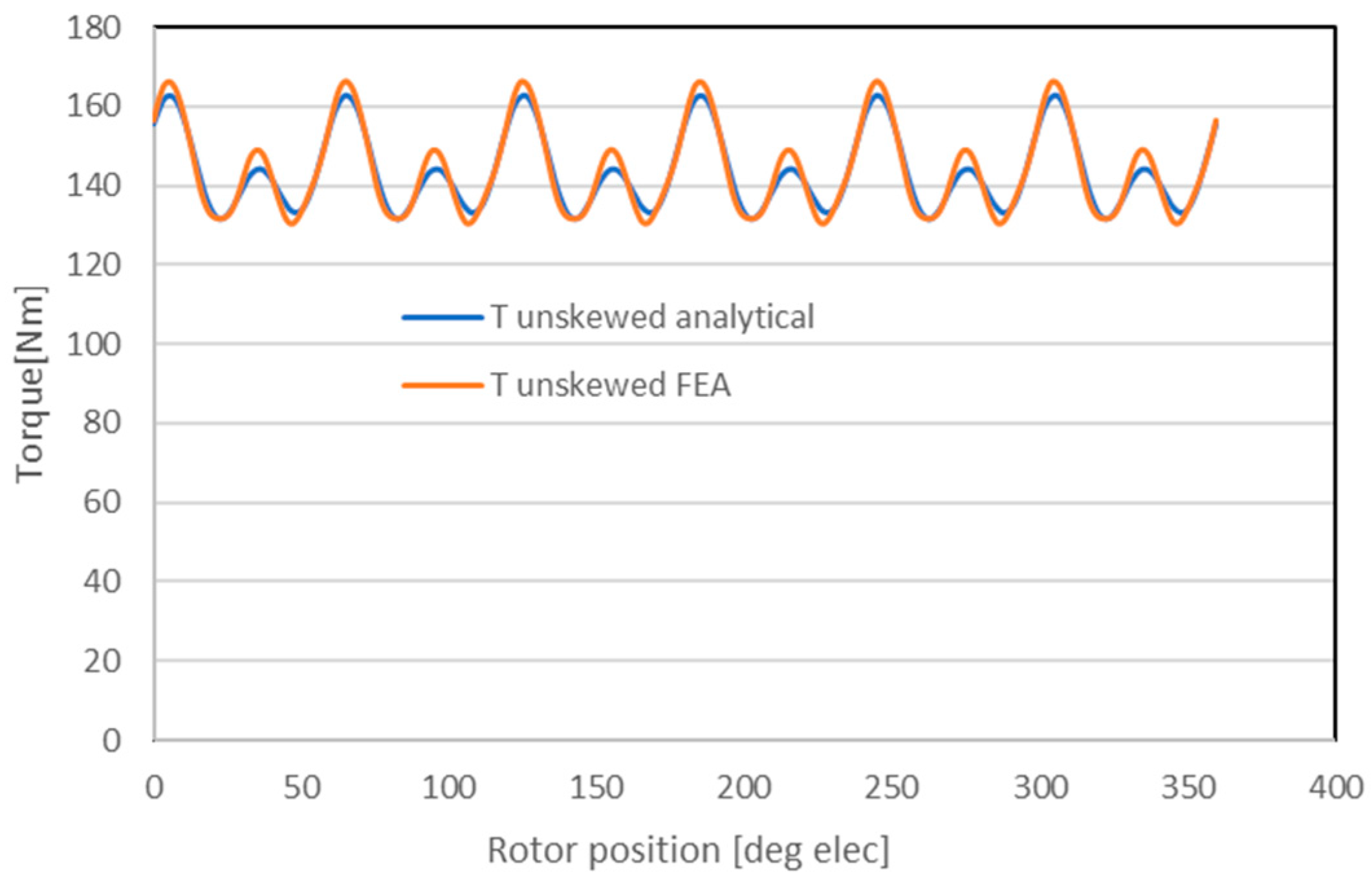
2.1. Torque Ripple
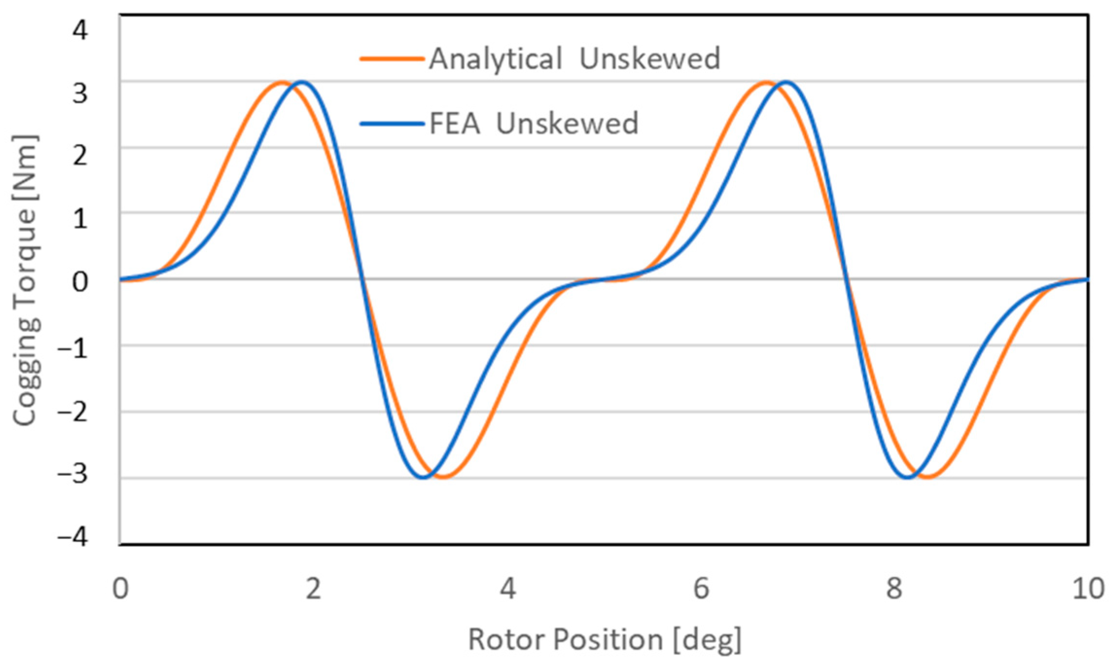
2.2. Cogging Torque
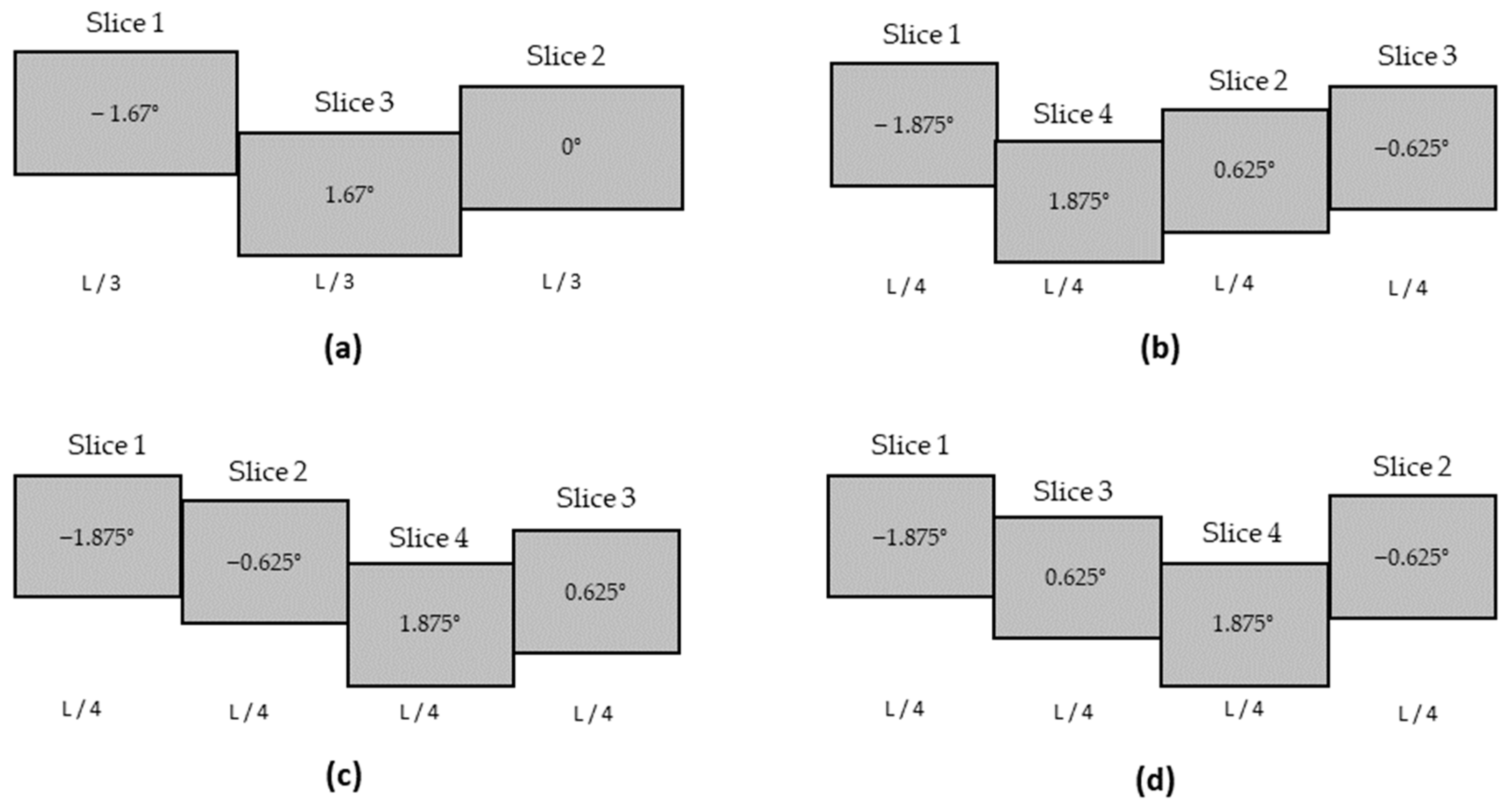
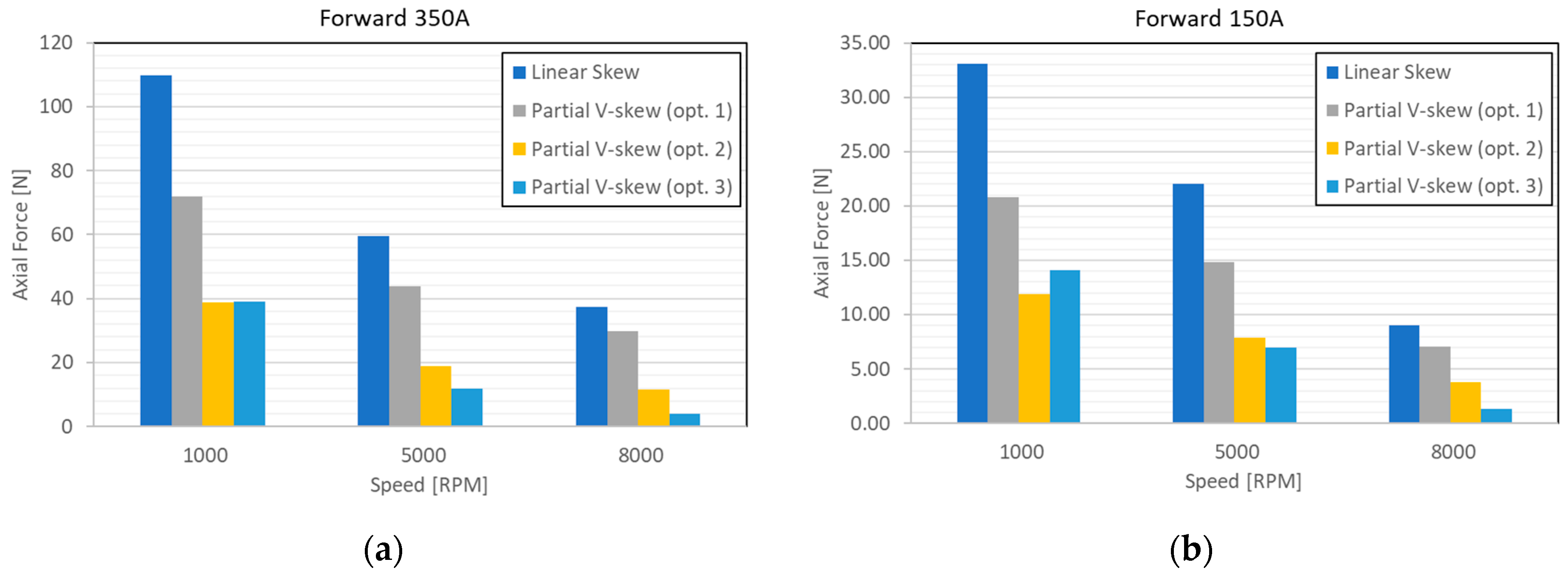
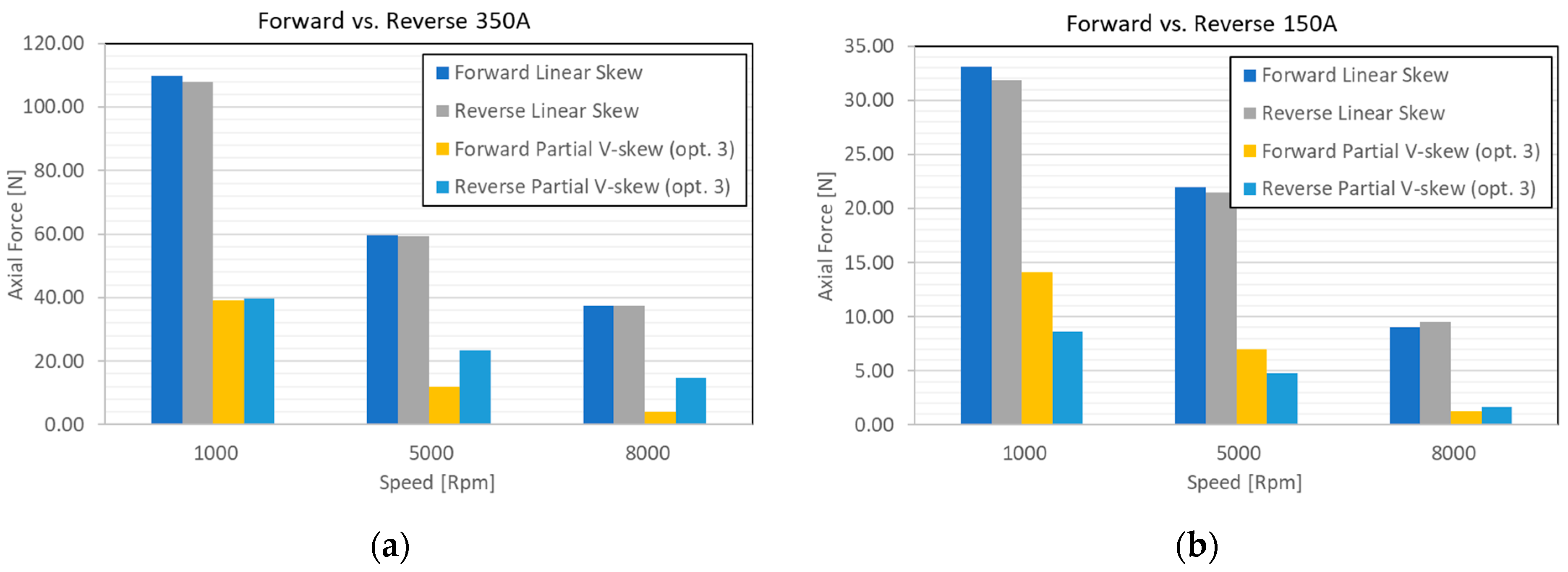
2.3. Axial Force
3. Two-Dimensional FEA Modeling
3.1. Torque Ripple Excitations without Skew
3.2. Impact of Stator Skew
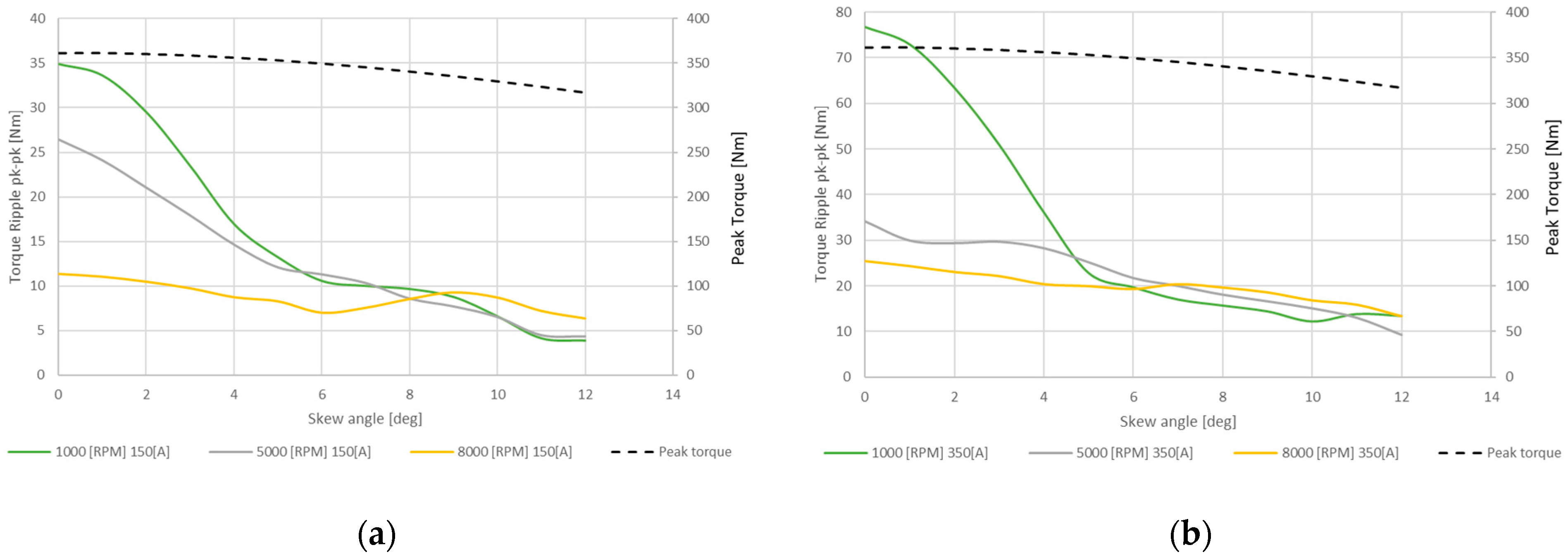
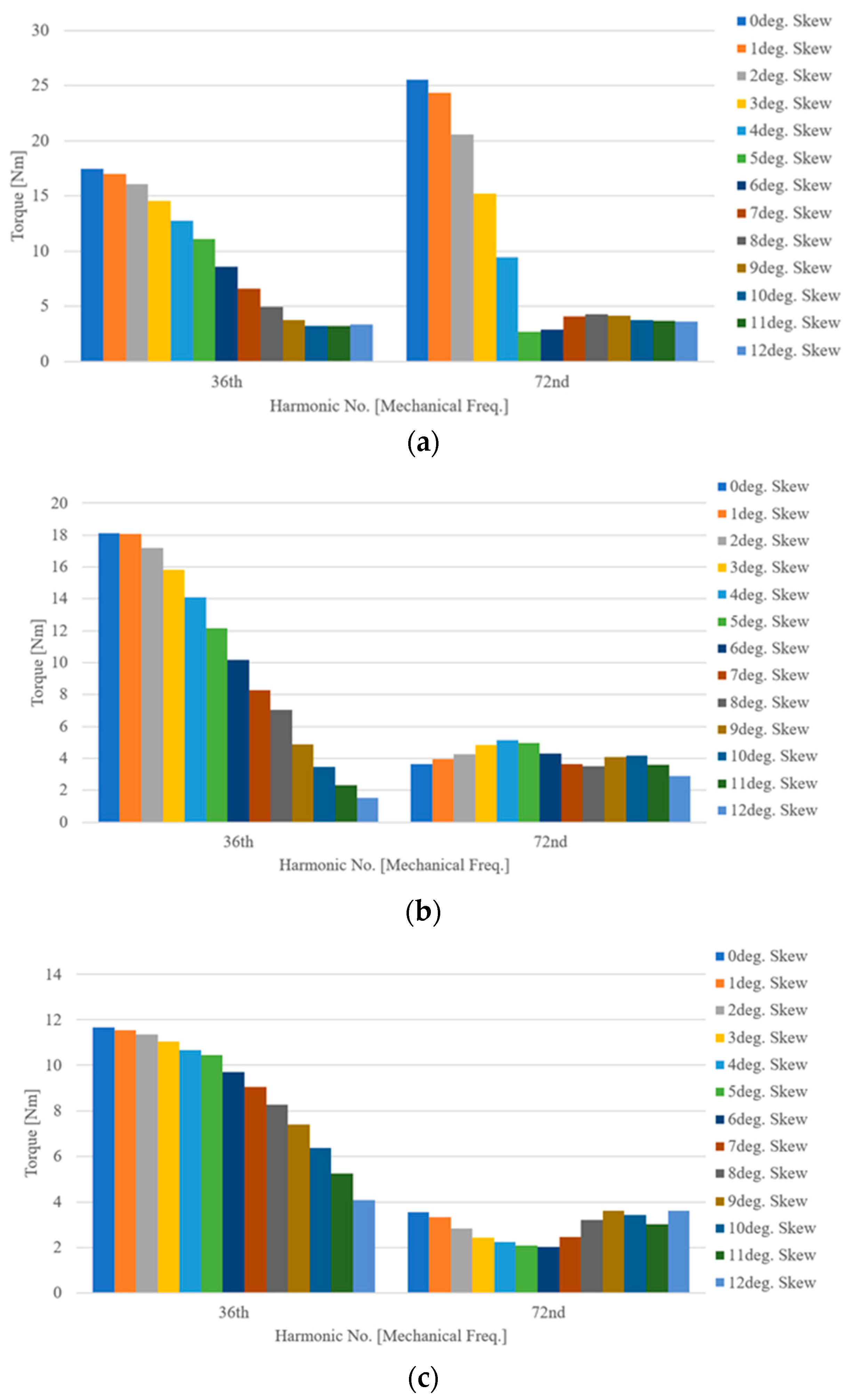
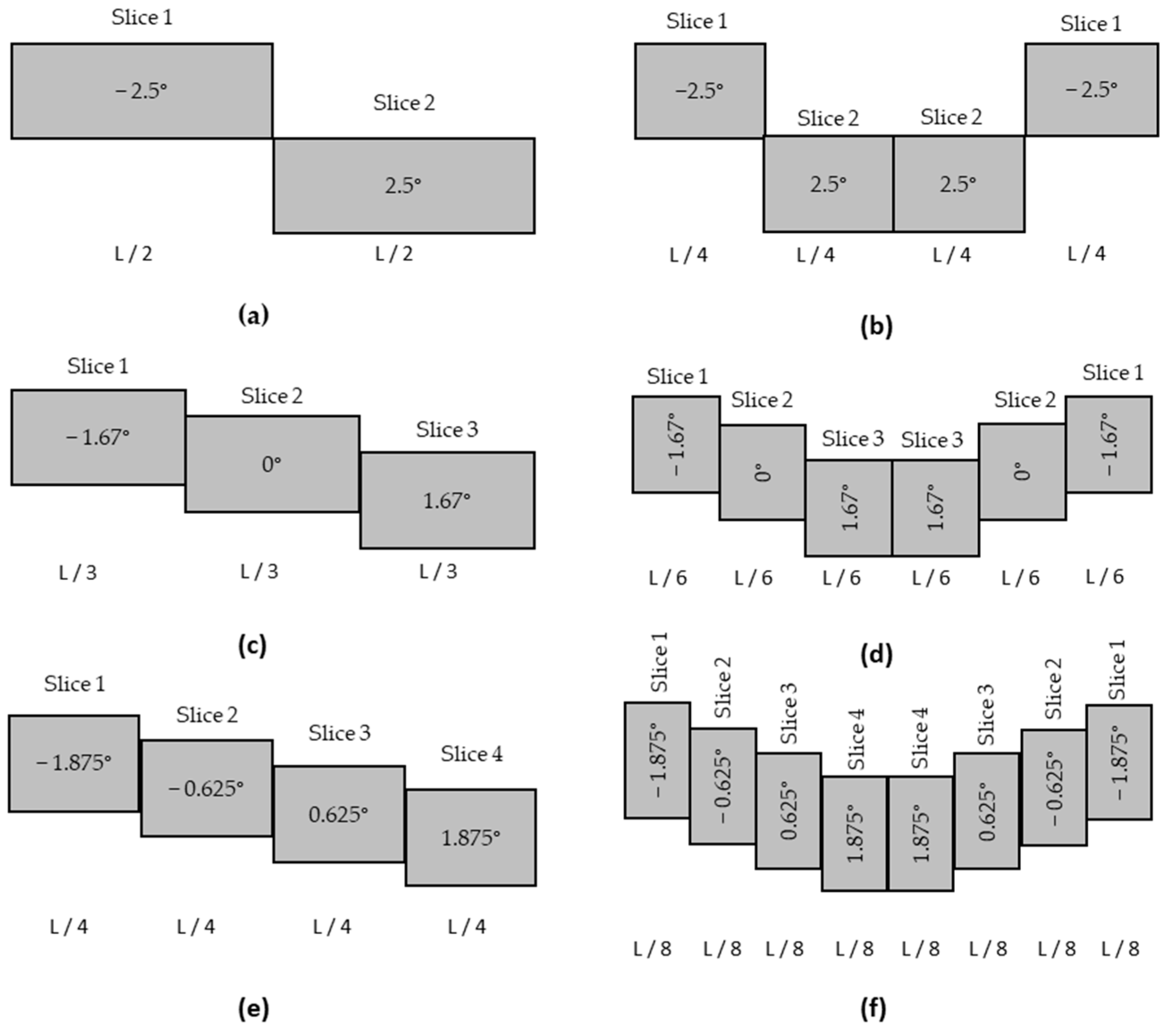
3.3. Impact of Rotor Skew
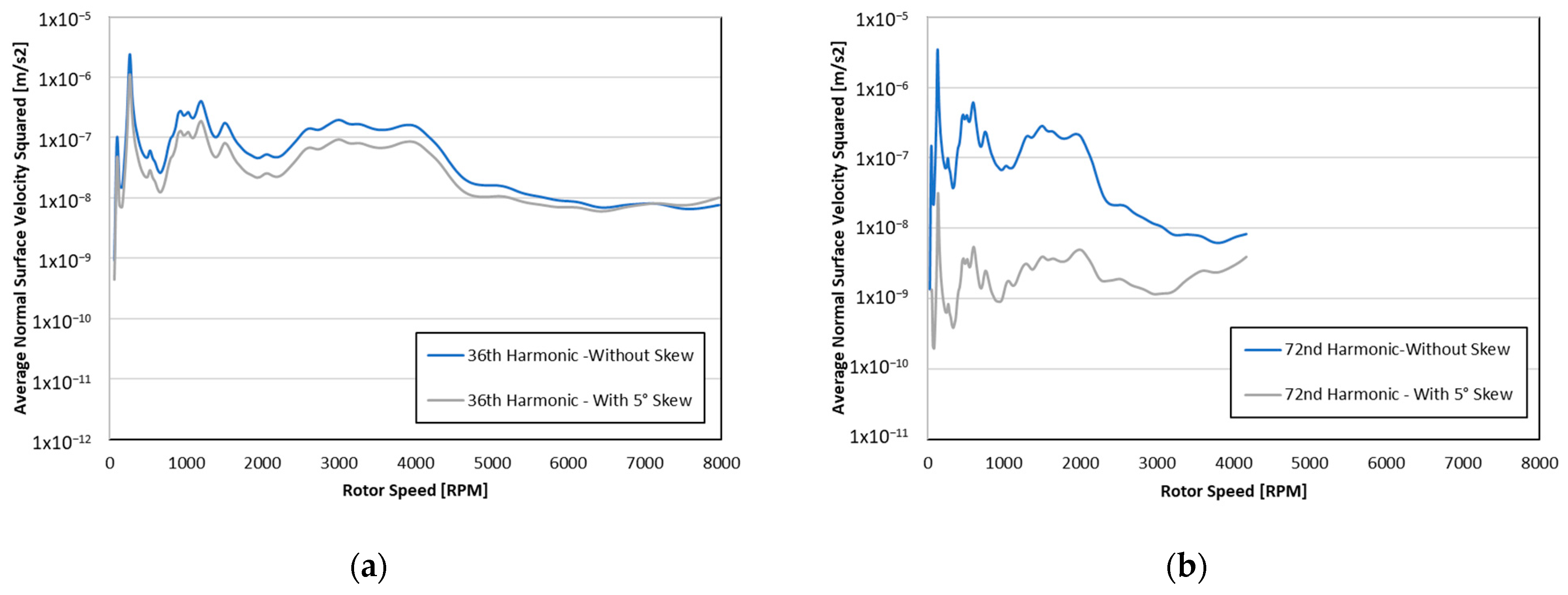
3.4. Impact of Skew on Back-EMF Harmonics
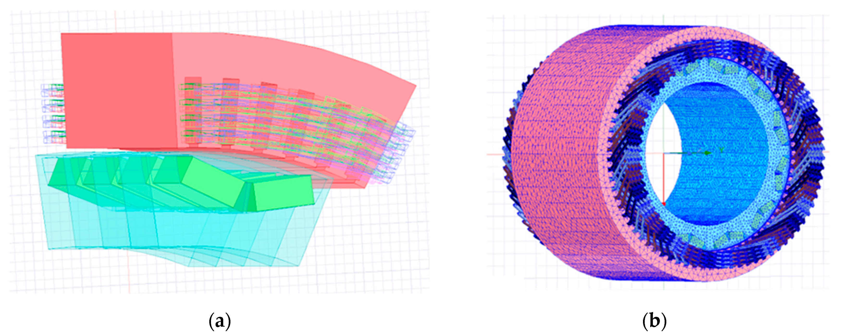
4. Three-Dimensional Finite Element Modeling of Axial Forces in IPM Rotors
5. NVH Structural Analysis
6. Impact of Skew on Rotor Manufacture
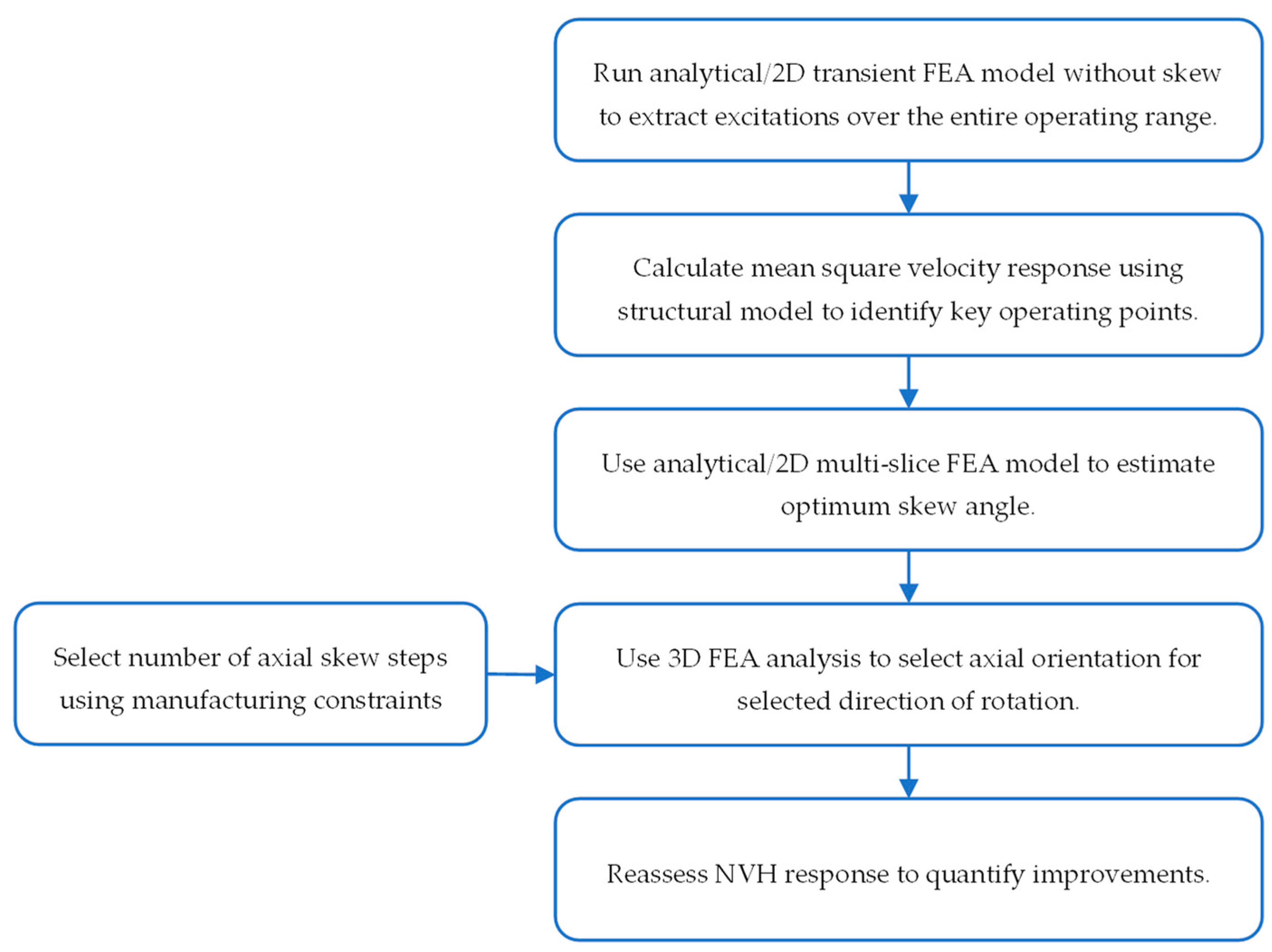
7. NVH Optimization Workflow
8. Conclusions
Author Contributions
Funding
Data Availability Statement
Conflicts of Interest
References
- He, S.; Momen, F.; Patruni, P.K.; Gsj, G. Analytical and Experimental Studies of Electric Motor NVH Design Focusing on Torque Ripple and Radial Force; SAE Technical Paper 2022-01-0311; SAE International: Warrendale, PA, USA, 2022. [Google Scholar] [CrossRef]
- Sun, T.; Kim, Y.-H.; Cho, W.-J.; Fang, L.; Hong, J.-P. Effect of pole and slot combination on noise and vibration in permanent magnet synchronous motor. In Proceedings of the 2010 14th Biennial IEEE Conference on Electromagnetic Field Computation (CEFC 2010), Chicago, IL, USA, 9–12 May 2010; p. 1. [Google Scholar]
- Lee, S.-H.; Hong, J.-P.; Hwang, S.-M.; Lee, W.-T.; Lee, J.-Y.; Kim, Y.-K. Optimal Design for Noise Reduction in Interior Permanent Magnet Motor. In Proceedings of the Conference Record of the 2006 IEEE Industry Applications Conference Forty-First IAS Annual Meeting, TAMPA, FL, USA, 8–12 October 2006. [Google Scholar]
- Ren, W.; Xu, Q.; Li, Q. Asymmetrical V-Shape Rotor Configuration of an Interior Permanent Magnet Machine for Improving Torque Characteristics. IEEE Trans. Magn. 2015, 51, 1–4. [Google Scholar] [CrossRef]
- Ha, T.-W.; Huh, J.-W.; Choi, S.-K.; Min, D.-W.; Chae, C.-K.; Abdy, A.; Schmitt, C.; Mahmoud, H.; Jain, S.; Rodrigues, L. Robust Development of Electric Powertrain NVH for Compact Electric SUV. SAE Int. J. Adv. Curr. Pract. Mobil. 2021, 3, 1038–1048. [Google Scholar] [CrossRef]
- Li, H.; Cui, M.; Zou, T.; Zhang, X.; Zhang, H.; Xu, Z.; Gerada, D.; Gerada, C. Radial Force Analysis and Optimization of Interior Permanent Magnet Traction Motor for Reduction of Electromagnetic Vibration. In Proceedings of the 2022 International Conference on Electrical Machines (ICEM), Valencia, Spain, 5–8 September 2022; pp. 1906–1912. [Google Scholar]
- Klausnitzer, M.; Moeckel, A. Methods for calculation of skewed permanent magnet motors for short and highly saturated motors. In Innovative Small Drives and Micro-Motor Systems; 9. GMM/ETG Symposium; IEEE: Berlin, Germany, 2013. [Google Scholar]
- Islam, R.; Husain, I.; A Fardoun, A.; McLaughlin, K. Permanent magnet synchronous motor magnet designs with skewing for torque ripple and cogging torque reduction. In Proceedings of the 2007 IEEE Industry Applications Annual Meeting, New Orleans, LA, USA, 23–27 September 2007; pp. 1552–1559. [Google Scholar] [CrossRef]
- Hwang, M.-H.; Lee, H.-S.; Cha, H.-R. Analysis of Torque Ripple and Cogging Torque Reduction in Electric Vehicle Traction Platform Applying Rotor Notched Design. Energies 2018, 11, 3053. [Google Scholar] [CrossRef]
- Park, G.-J.; Kim, Y.-J.; Jung, S.-Y. Design of IPMSM Applying V-Shape Skew Considering Axial Force Distribution and Performance Characteristics According to the Rotating Direction. IEEE Trans. Appl. Supercond. 2016, 26, 1–5. [Google Scholar] [CrossRef]
- Ge, X.; Zhu, Z.Q.; Kemp, G.; Moule, D.; Williams, C. Optimal Step-Skew Methods for Cogging Torque Reduction Accounting for Three-Dimensional Effect of Interior Permanent Magnet Machines. IEEE Trans. Energy Convers. 2017, 32, 222–232. [Google Scholar] [CrossRef]
- Blum, J.; Merwerth, J.; Herzog, H.-G. Investigation of the segment order in step-skewed synchronous machines on noise and vibration. In Proceedings of the 4th International Electric Drives Production Conference (EDPC), Nuremberg, Germany, 30 September–1 October 2014; pp. 1–6. [Google Scholar]
- Hwang, S.-M.; Eom, J.-B.; Hwang, G.-B.; Jeong, W.-B.; Jung, Y.-H. Cogging torque and acoustic noise reduction in permanent magnet motors by teeth pairing. IEEE Trans. Magn. 2000, 36, 3144–3146. [Google Scholar] [CrossRef]
- Zhu, L.; Jiang, S.Z.; Zhu, Z.Q.; Chan, C.C. Analytical Methods for Minimizing Cogging Torque in Permanent-Magnet Machines. IEEE Trans. Magn. 2009, 45, 2023–2031. [Google Scholar] [CrossRef]
- Jung, J.-W.; Kim, D.-J.; Hong, J.-P.; Lee, G.-H.; Jeon, S.-M. Experimental Verification and Effects of Step Skewed Rotor Type IPMSM on Vibration and Noise. IEEE Trans. Magn. 2011, 47, 3661–3664. [Google Scholar] [CrossRef]
- Holehouse, R.; Shahaj, A.; Michon, M.; James, B. Integrated approach to NVH analysis in electric vehicle drivetrains. J. Eng. 2019, 2019, 3842–3847. [Google Scholar] [CrossRef]


| Parameter | Value | Unit |
|---|---|---|
| Number of slots—Q | 72 | - |
| Number of poles—2p | 12 | - |
| Motor torque | 400 | Nm |
| Motor maximum speed | 8700 | rpm |
| Maximum Voltage | 400 | V |
| Maximum Power | 155 | kW |
| Maximum Current | 400 | A |
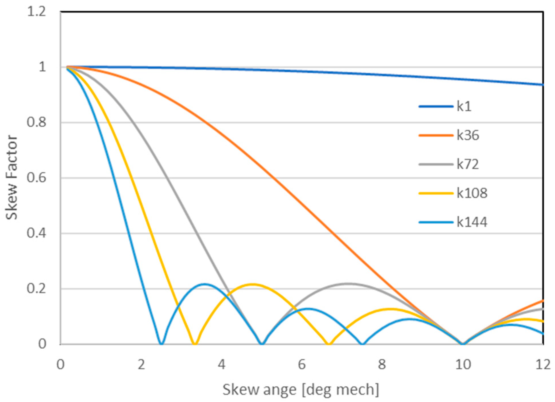
| Order | Harmonic | Excitation |
|---|---|---|
| 1 | 36 | Torque ripple |
| 2 | 72 | Cogging + Torque ripple |
| 3 | 108 | Torque ripple |
| 4 | 144 | Cogging + Torque ripple |
| Skew Method | Harmonic Distortion Back-EMF Line-Line Voltage (%) |
|---|---|
| Non-skewed | 9.7 |
| 5° rotor skew (2 slices) | 4.5 |
| 5° rotor skew (4 slices) | 4.1 |
| 5° stator skew | 4.0 |
| 10° stator skew | 1.3 |
| Total Axial Force (N) | ||||
|---|---|---|---|---|
| Linear Skew | Partial V-Skew (Opt. 1) | Partial V-Skew (Opt. 2) | Partial V-Skew (Opt. 3) | |
| Analytical Approximation | −29.9 | −19.9 | −9.9 | 10.0 |
| 3D FEA Simulation | −31.9 | −19.7 | −9.1 | 8.6 |
| Error | 6.4% | −1.0% | −9.1% | −15.7% |
| Number of Stacks | Magnet Insertions | Equivalent Axial Length Reduction |
|---|---|---|
| ( ) | ( ) | (%) |
| 2 | 48 | 0.19 |
| 3 | 72 | 0.29 |
| 4 | 96 | 0.39 |
| 6 | 144 | 0.58 |
| 8 | 192 | 0.77 |
Disclaimer/Publisher’s Note: The statements, opinions and data contained in all publications are solely those of the individual author(s) and contributor(s) and not of MDPI and/or the editor(s). MDPI and/or the editor(s) disclaim responsibility for any injury to people or property resulting from any ideas, methods, instructions or products referred to in the content. |
© 2023 by the authors. Licensee MDPI, Basel, Switzerland. This article is an open access article distributed under the terms and conditions of the Creative Commons Attribution (CC BY) license (https://creativecommons.org/licenses/by/4.0/).
Share and Cite
Cawkwell, T.; Haris, A.; Gonzalez, J.M.; Rodrigues, L.K.; Shirokov, V. A Methodology for Applying Skew in an Automotive Interior Permanent Magnet Rotor for Robust Electromagnetic and Noise, Vibration and Harshness Performance. World Electr. Veh. J. 2023, 14, 350. https://doi.org/10.3390/wevj14120350
Cawkwell T, Haris A, Gonzalez JM, Rodrigues LK, Shirokov V. A Methodology for Applying Skew in an Automotive Interior Permanent Magnet Rotor for Robust Electromagnetic and Noise, Vibration and Harshness Performance. World Electric Vehicle Journal. 2023; 14(12):350. https://doi.org/10.3390/wevj14120350
Chicago/Turabian StyleCawkwell, Thomas, Ahmed Haris, Juan Manuel Gonzalez, Leon Kevin Rodrigues, and Vladimir Shirokov. 2023. "A Methodology for Applying Skew in an Automotive Interior Permanent Magnet Rotor for Robust Electromagnetic and Noise, Vibration and Harshness Performance" World Electric Vehicle Journal 14, no. 12: 350. https://doi.org/10.3390/wevj14120350