1. Introduction
In recent years, there has been an increasing interest in reducing the required time for product development to improve their stages and processes. It is well known that recent vehicles integrate more sensors, decreasing computing systems to control and monitor the vehicle measurements. However, this enhancement significantly increases the complexity of predicting vehicle dynamic behavior. Hence, there are several advanced driver assistance systems (ADAS) to improve user safety and mobility, such as lane departure warning, adaptive cruise control, lane-change systems, side assist, parking assistance, blind-spot warning, and forward collision warning [
1]. These assists can be used to communicate between one vehicle and another to reduce collision risk during lane changing and car following [
2,
3]. These assists improve active driving safety because, when integrated with radar or cameras, they allow the vehicle to behave intelligently, initially as a warning or by making decisions based on different driving conditions simulated and tested as hardware in the loop. This on-board system allows the analysis of the real-time behavior of vehicle dynamics [
4]. Integrating electric power trains modifies the vehicle’s dynamic response because electric vehicles are heavier. However, they have fewer components, and the energy storage system modifies the vehicle’s center of mass, which causes the longitudinal and transverse forces to change. While the center of mass is lower, improving stability, the transfer of forces between suspended and non-suspended masses generates a change in the handling conditions depending on the handling conditions, affecting the energy consumption from tank to wheel [
5].
It is therefore important to employ engineering systems to develop a process involving all the complexities of each assistance. The main challenges many researchers face are reducing development time and integrating updated information at early design stages. Up to now, vehicle stability has been improved using chassis control systems to achieve electronic stability. This system can also improve vehicle and driving behavior, resulting in an active safety system to prevent accidents. This kind of system is also employed to enhance consumption performance as assistance to reduce slip and skidding. The prediction of the slip angle is essential to improve the active safety of the vehicle [
6]. This is because these systems can control forces at each wheel to stabilize the vehicle based on the direct-yaw-moment control at each wheel to recover and improve vehicle stability.
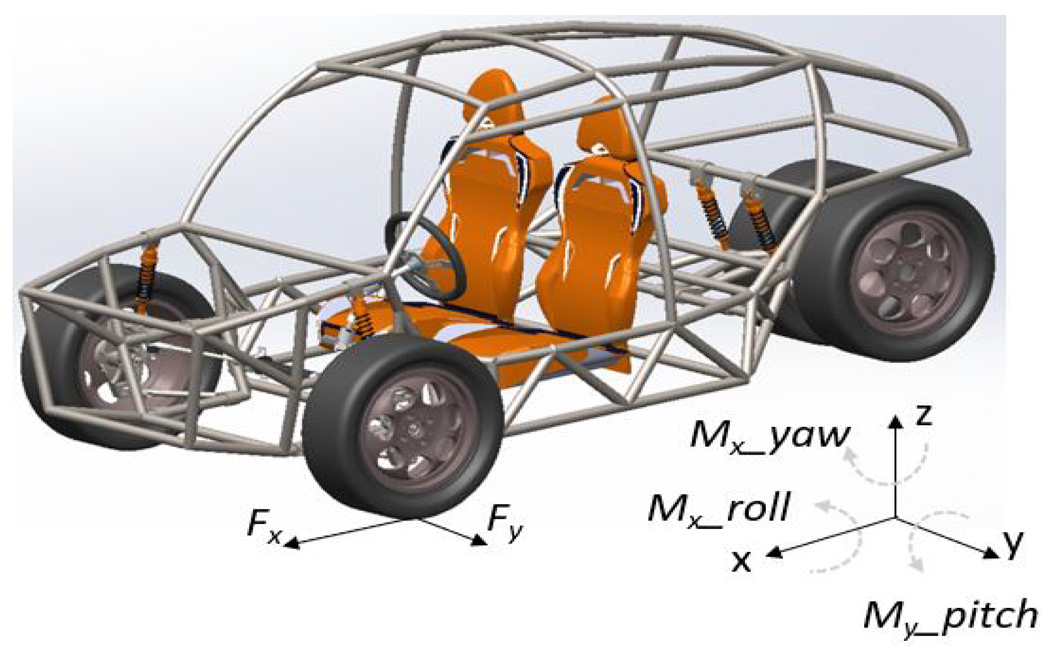
Figure 1 shows the configuration of the frame of the monocoque structure, the suspension system, and the power train. It is a two-passenger vehicle with a cargo section. The transfer of forces between the vehicle and the road is at the wheel’s point of contact with the vehicle. The longitudinal traction forces are transmitted to the floor by two processes of the viscoelastic characteristics of the wheel: physical adhesion and local deformation or hysteresis friction, depending on the type of material used. It has a front engine, and the batteries are located on the platform of the body, under the seats.
Yaw monitoring can be used to warn of an unstable driving condition and control slip. Powertrain traction settings change load transfers due to tractive forces [
7,
8]. Due to its dynamic characteristics, the slip ratio is used not only as a vehicle control system [
9] but also to estimate fuel consumption [
10]. It also analyzes the vehicle’s dynamics to decrease the risk of losing control; therefore, these systems actively assist the driver. Although the car body design has an effect when the car is doing any maneuvering, it is when the driver can perceive a low torsional stiffness as a delay in the vehicle’s behavior with the road.
Conversely, the longitudinal stiffness contributes to the transmission of forces under acceleration and braking conditions. It is noted that these mechanical characteristics are passive, unlike the measurement under driving conditions, which is an active process that can be employed to improve vehicle dynamics using parameter combinations. These parameters might involve driver performance, cargo, and others from unexpected changes such as in environment, temperature, and rain. All these parameters can change the forces between the wheel and the road, altering the vehicle’s response.
It is well known that it is a typical maneuver lane change during driving to change direction, rebound, merge on roads, or exit. This maneuver can be predicted from the vehicle inside using movements and/or gestures’ driver. It can also be anticipated by the interaction between the vehicular flow and the road, by some unforeseen event. All these events can affect the vehicle dynamic even with assist sensors.
Xing et al., [
11] proposed a driver intention inference system, which can eventually be included in ADAS. This research was focused on the highway lane-change maneuvers to improve safe driving, evaluating traffic state and dangerous situations. Driver intention anticipation is important because only half of the drivers turn on signals before lane-change maneuvers. To predict these intentions can also reduce traffic congestion [
12,
13]. Although these systems are considered the lowest automation levels (Levels 1 and 2), there is evidence that they contribute to lane maintenance [
14].
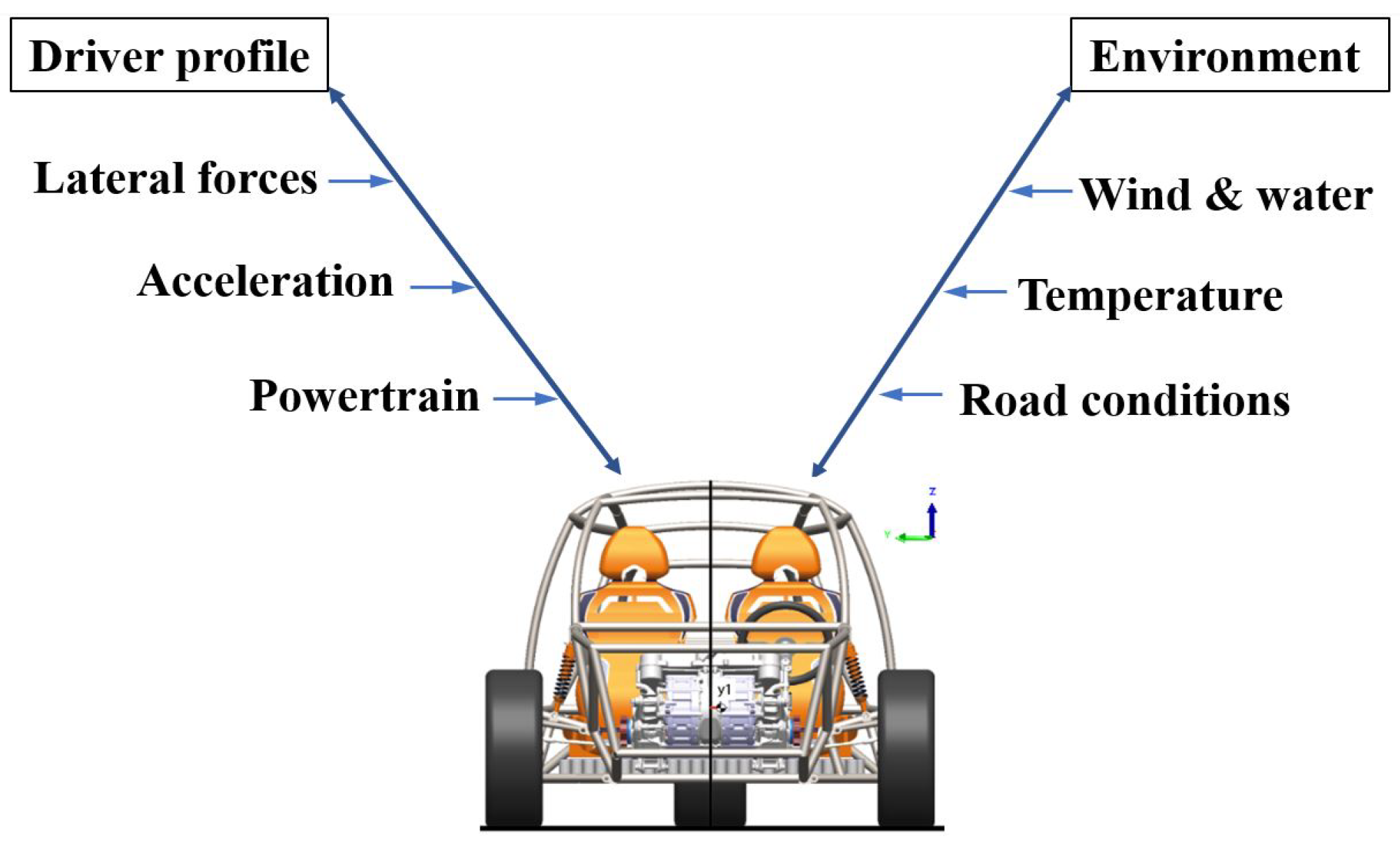
The automotive development process defined the vehicle parameters as expected targets. However, all these parameters are connected between them and have a strong influence on the vehicle properties. It is then this complex connection that needs to perform different assessments through the development process, from the concept stages toward the start of production. Therefore, the design and evaluation processes require improvement by implementing methodologies such as system engineering. Consequently, a model is employed to connect parameters, which can update different subsystems on different levels of vehicle details. So, the whole vehicle describes the main structure of levels involving subsystems or sub-assemblies and component levels. If a structure is connected based on a parametric model, any change in a model component can update the behavior at the full vehicle level. Vehicle dynamic is the result of all its systems working together. These systems can be chassis, suspension, brakes, and drivetrains. The iteration between all these systems would affect user comfort and safety on the same road under different driving conditions. These conditions can also be varied in the same car with different driver performance. Other conditions include environmental, road characteristics, road gradients, temperature, rain, wind, and traffic conditions, as illustrated in
Figure 2.
Factors that influence the vehicle’s dynamics can be controlled either by the vehicle designer or directly by the driver, such as the characteristic acceleration profile of the wheel grip due to the generated friction. However, other parameters, such as road and ambient temperature, cannot be controlled. The same vehicle with the same characteristics varies in performance and response only by the type of driver; this creates the need to integrate nonlinear processes to predict and estimate vehicle response under all direct and indirect variables.
Several studies have employed a non-parametric model based on artificial neural networks (ANNs) to predict nonlinear dynamic responses [
15]. One of these studies reported that overfitting is a typical problem during the training process, and it needs to be avoided using an optimal inputs/outputs correlation. It also employed Bayesian techniques to estimate error during the training process [
16]. ANNs have also been employed for vehicle applications such as emission [
17], energy consumption [
18,
19], and reduction of structural vibrations to improve ride comfort. Artificial Intelligence has been integrated into the development of powertrains; in the gear drivetrain development, its complexity is due to a smooth perception during driving [
20]. Lee et al. [
21] reported a deep learning model to predict lane-change maneuvers based on longitudinal and lateral acceleration or deceleration actions. Another work improved active safety by analyzing the driver distraction based on speed, lane offset, and steering changes [
22]. It is well known that the main tractions of a vehicle’s forces are transmitted through wheels. Furlan et al. [
23] presented an implementation of ANNs to predict viscoelastic behavior and the relationship between vehicle speed and road friction. The improvement of powertrains requires standard assistant systems such as cruise control and throttle control enhancing loop control to reduce emission; this problem was solved using ANNs [
24,
25]. It was also reported that the longitudinal wheel slip control under driver behavior uncertainty, environment, and road changes can be improved via ANNs [
26]. A multibody model can be evaluated utilizing ANNs trained with a data-driven model approach [
27,
28]. Neural networks can also be exploited to improve the lateral and longitudinal dynamics using vehicle data such as steering angle and torque [
29].
Taghavifar et al. [
30] proposed a non-parametric model based on ANNs to improve vehicle longitudinal and lateral dynamics, enhancing stability and maneuverability. Yaw moment is used to improve vehicle stability, which can be affected by lateral wing forces, disturbance on the trajectory, severe maneuvers, and sudden lane change to prevent collisions [
18]. This study provides new insights into ANN implementations to integrate its use in multibody dynamic simulations in a platform development process. The actual implementation involves a dynamic recurrent neural network named nonlinear autoregressive exogenous (NARX); this network has at least one feedback loop with time delays, making this ANN dynamic. The tapped delay lines on its inputs contain multiple delays, which can be considered ‘memory’. This feature successfully employs this work due to the input number employed during training. It is also important to note that this kind of neural network modeling can be used as a virtual sensor, which can also be implemented on older cars to improve passenger safety under unexpected maneuvers.
2. Artificial Neural Network
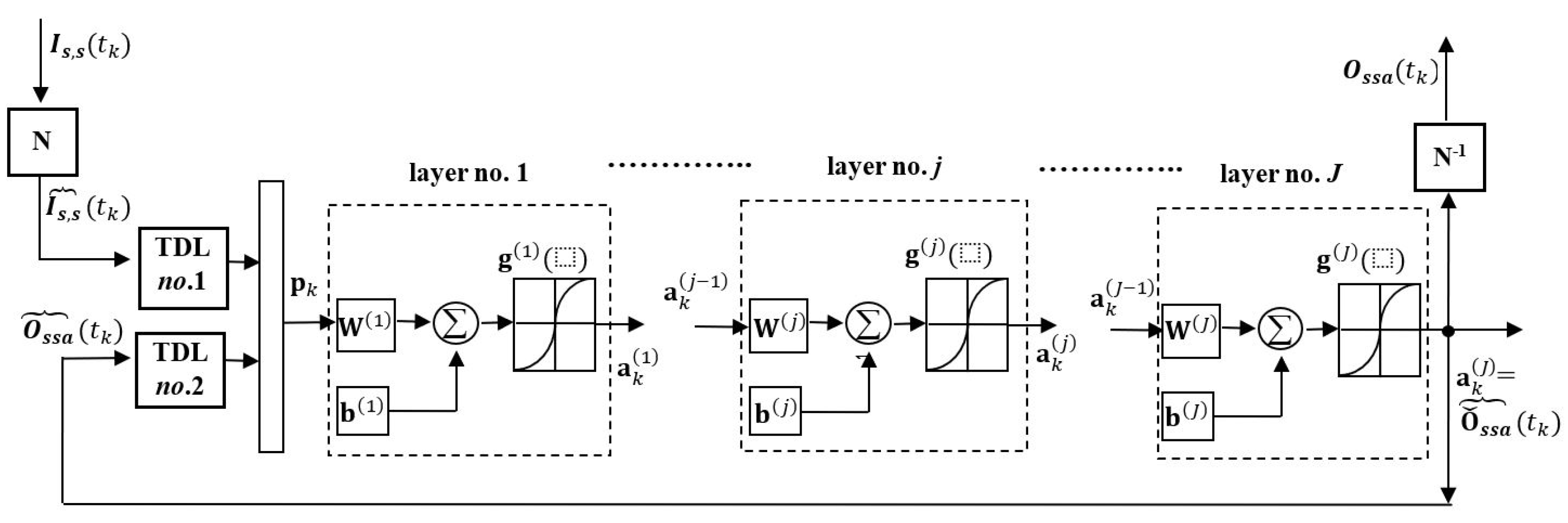
This paper employs a time-series modeling scheme based on the nonlinear autoregressive exogenous (NARX) scheme [
15]; this kind of modeling involves memory (as illustrated in
Figure 3). Such a scheme can be implemented using a recurrent neural network (RNN). The inputs are of two types of data; the first ones involve the time histories simulated data of the following variables: time, velocity, longitudinal acceleration, lateral acceleration, yaw angle, yaw rate, yaw acceleration, pitch angle, pitch rate, roll angle, roll rate, engine speed, steering rack travel, and steering wheel angle. The second one is synthetic data, which are the angular velocity of the wheel, slip ratio, normal forces, and relationship of the angle’s pitch/yaw and roll/yaw. As presented in
Figure 3, those inputs are compressed
, where
, denotes discrete times, with
being the sampling time resolution. On the other hand, the network’s output estimate for
, which is the side slip angle. As stated in [
31], the inputs and outputs require to be normalized for network use in the range of [−1, 1], where
denotes the network-normalized version of the variable (□) As previously mentioned, this system has memory the tapped delay lines (
), which are channels containing past values of the input and output (feedback) signals.
Concerning
Figure 3, one can define
as the number of neurons at each
jth layer, then
J can be the total number of layers and
,
the numbers of delays in
No. 1 and
No. 2, respectively. If
is the
× 1 vector comprising the signal outputs of the
jth layer, then one can define
as the compressed signals to Layer No. 1, where
is the
× 1 column matrix expressed as:
where
and
are the number of delays in their respective
. For the sake of clarity, the subscript “
a” is dropped in the following part. If
is the
× 1 vector comprising the signal outputs of the
jth layer, then:
where
and
are, respectively, the matrix of the weights and vector of biases of the
jth layer, and
is a vector operator comprising the transfer functions of the neurons of the
jth layer. It is also noted that the network is always initialized so that, in
(Equation (
1)),
The RNN model in
Figure 3 was implemented for a general purpose using technical computing software with a neural network facility [
31]. The RNN was subjected to input/output training data for a given user-prescribed architecture. The training procedure employed the Levenberg–Marquardt optimization method to determine the optimal weights and biases that minimize the mean square value of the error (difference)
between the output of the actual data and predicted data for a given input to a value below a set tolerance specification. The network had 1 layer with 26 neurons and
delays for the input and
delays for the feedback. In this case, it is the binary sigmoid transfer function.
There are various benefits to using the Levenberg-Marquardt algorithm. It is more computationally efficient than the Gauss-Newton approach and converges faster than the steepest descent method. Additionally, by modifying the damping setting, problems with poor conditions are better managed.
3. Vehicle Dynamics with Neural Network
Vehicle dynamics are associated with the three main axes that describe the configuration of a vehicle, according to SAE J182. In the x-axis, the forces of acceleration and braking depend on the resistance to motion in the case of acceleration, which depends on the energy and power required to overcome them. Most forces are transmitted through the non-suspended masses, i.e., the wheels. Hence, the efficiency of the engine and the whole powertrain is important, as many elements have losses due to inertial forces and the characteristics of each system.
The y-axis is associated with transverse forces, which affect stability and behavior in curves. It is interested in preventing skidding, oversteering, and understeering conditions.
The vertical vehicle dynamics, described by the z-axis, is where the primary and secondary elements of the suspension system, the shock absorbers, and springs work. It is required to control the vertical accelerations of the body, improve handling, and increase safety.
During driving, nonlinear processes are performed; due to this, it is important to estimate and correct dynamic conditions of the vehicle with sensors, on-board systems, and algorithms that evaluate the behavior and response under different driving conditions. The dynamic resistance of the vehicle depends on the resistance to rolling by the required traction forces on the wheels. Aerodynamic loads that are a function of vehicle characteristics, wind speed, and also vehicle speed, fluid dynamics suggest an effect by vehicles and conditions around the same vehicle. Another variant of driving resistance depends on the condition of the road, not only whether it is paving or the characteristics of the pavement, but also on the slopes.
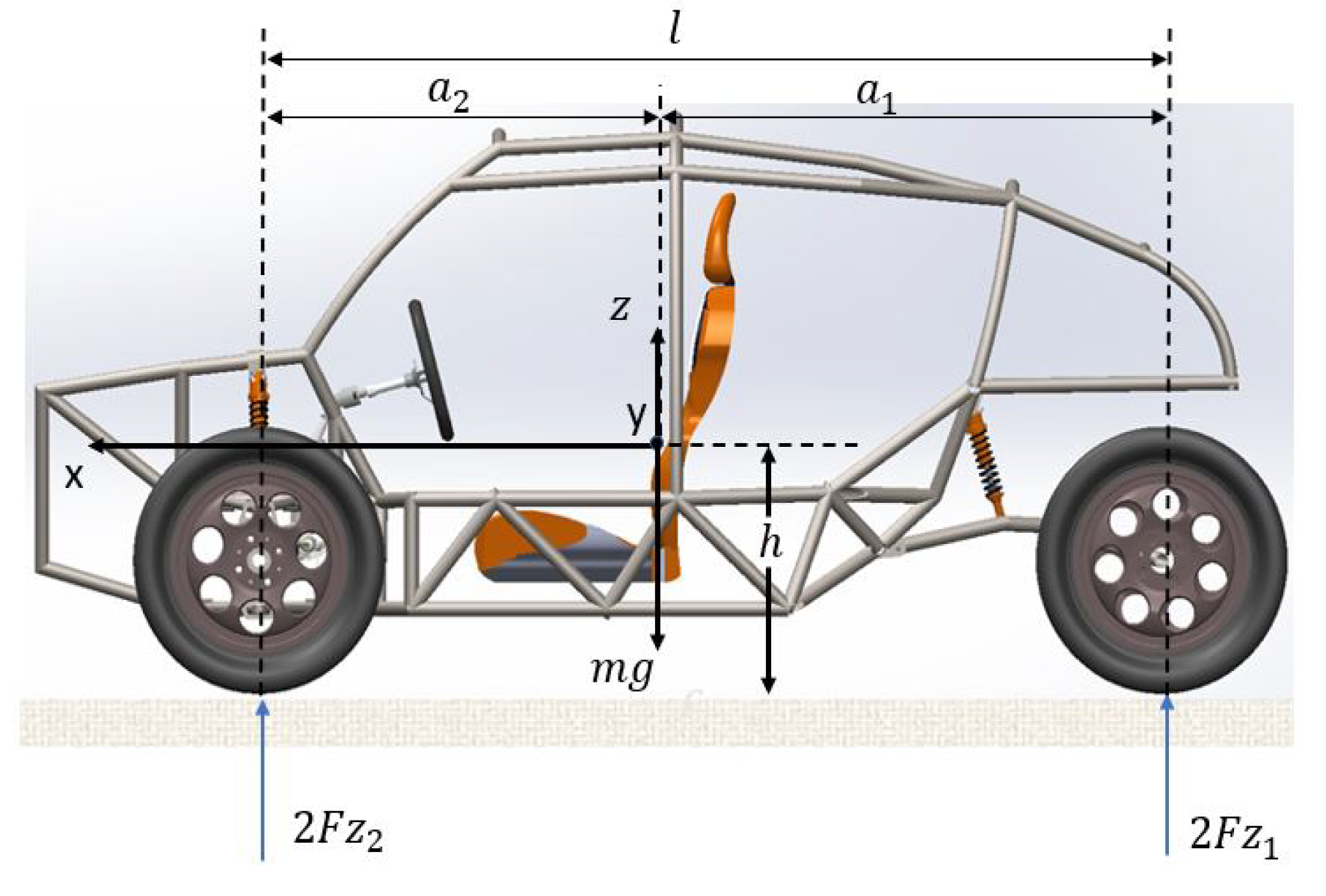
In order to understand load transmission between the non-suspended mass and the road, the evaluated longitudinal vehicle dynamics are shown in
Figure 4.
The normal forces are evaluated using Equations (
6) and (
7)
where the normal forces
are evaluated as a function of the transmission of the acceleration
,
m is the mass, and
g expresses the acceleration of gravity and the distance between the center of mass with the frontal axle
and rear axle
, respectively.
Normal forces have two components: the static and the dynamic part. The first is based on the position of the center of gravity; depending on the configuration of the drivetrain, the longitudinal position is modified. The second part of the equation describes the dynamic behavior when accelerating; because of this, the second term of the equation is subtracted from the front axle, but in the rear, normal forces are added.
The vehicle’s velocity depends on the angular velocity
of the wheel and its effective radius
.
Based on the velocity and the maneuver are found parameters of vehicle dynamics as longitudinal acceleration, lateral acceleration, yaw angle, yaw rate, yaw acceleration, pitch angle, pitch rate, roll angle, roll rate, engine speed (rpm), steering rack travel, and steering wheel angle.
The longitudinal slip ratio of a tire is expressed by
where
is the tire’s unloaded radius,
is the tire’s angular velocity, and
is the forward velocity. Slip ratio
s is positive for driving or negative for braking.
To evaluate the vehicle’s dynamic conditions, it is subjected to driving conditions and routes that allow the development of standardized test methods to know the response of different vehicles under the same driving condition. The severe lane-change maneuver is evaluated to prevent loose control as the double lane change, as described in ISO 3888. This improves the active safety impacting the driver, occupants, pedestrians, or other vehicles for emergency braking. Simulation velocities at 40, 50, 60, and 70 km/h are used to analyze its behavior. The normal forces play a crucial role in vehicle dynamic control systems, and an accurate estimation of them could substantially improve vehicle handling and safety. Variations of the vehicle mass and the suspension system substantially affect the roll and pitch dynamics.
This proposal is for an electric vehicle of 4 wheels, with a configuration of two wheels frontal and two wheels rear (2F/1R). The configuration described corresponds to a three-wheeled vehicle. However, the rear axle has two wheels, as
Figure 1 describes. The main target is not only for city use but also for off-road conditions. The wheels are 195/50 R15. The main characteristics of the vehicle are summarized in
Table 1.
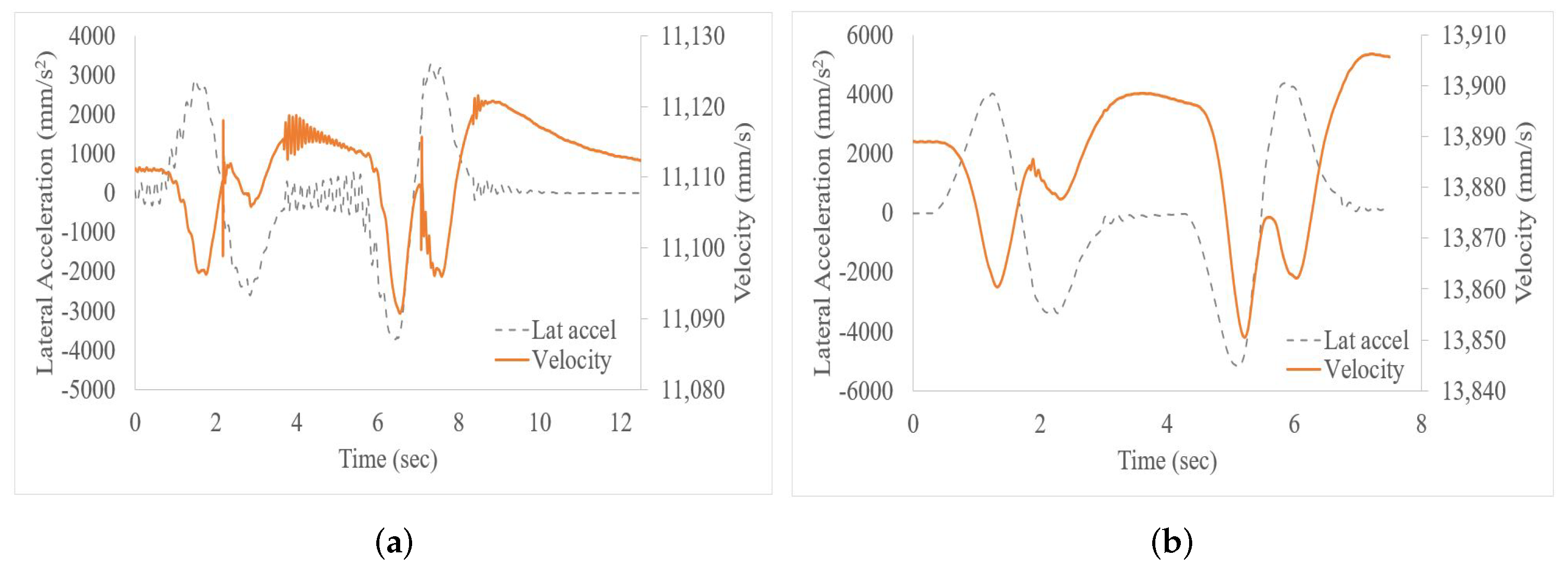
Based on the multibody simulation using Adams Car, the vehicle responses are shown in
Figure 5 and
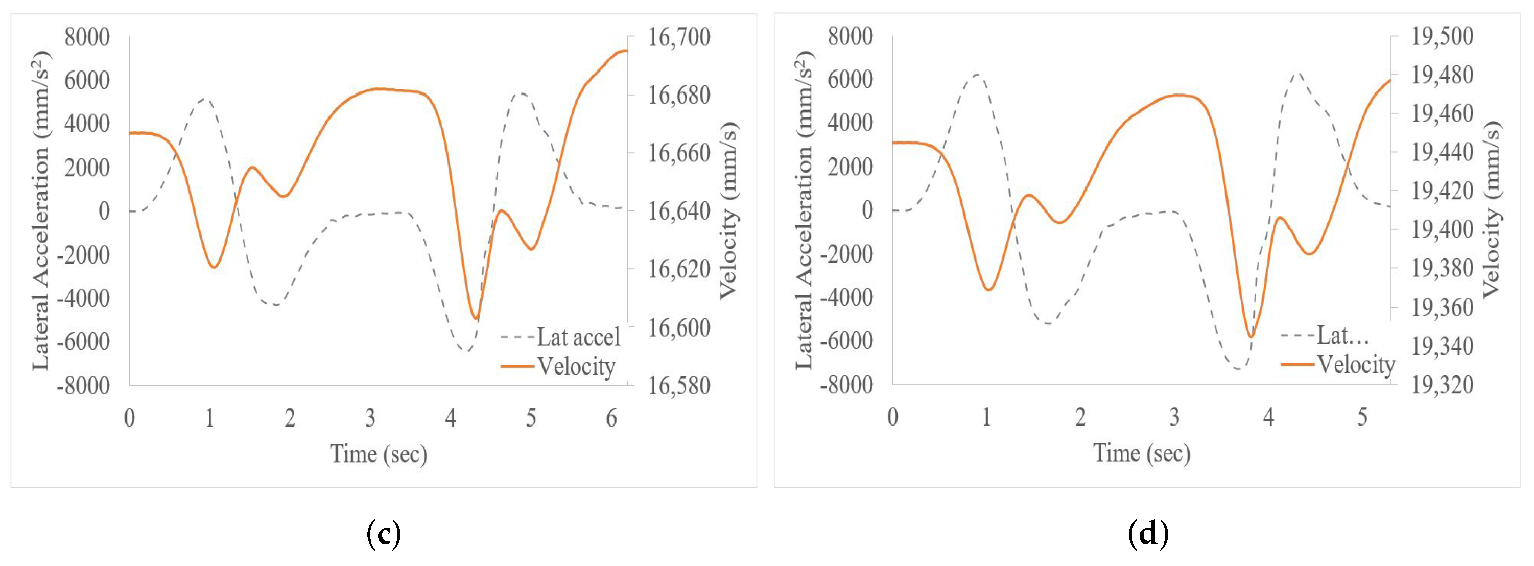
Figure 6.
Figure 5 shows the history of lateral acceleration and the respective velocity. The time needed to complete the maneuver depends on the speed. The central zone is observed when the vehicle is in the lane change; before and after this zone is the behavior to perform the lane-change maneuver.
Figure 6 shows the angles required for double lane change at different speeds. Interestingly, this correlation is related to the taw angle remaining constant by being the same maneuver. However, the pitch angle increases directly proportional to the speed.
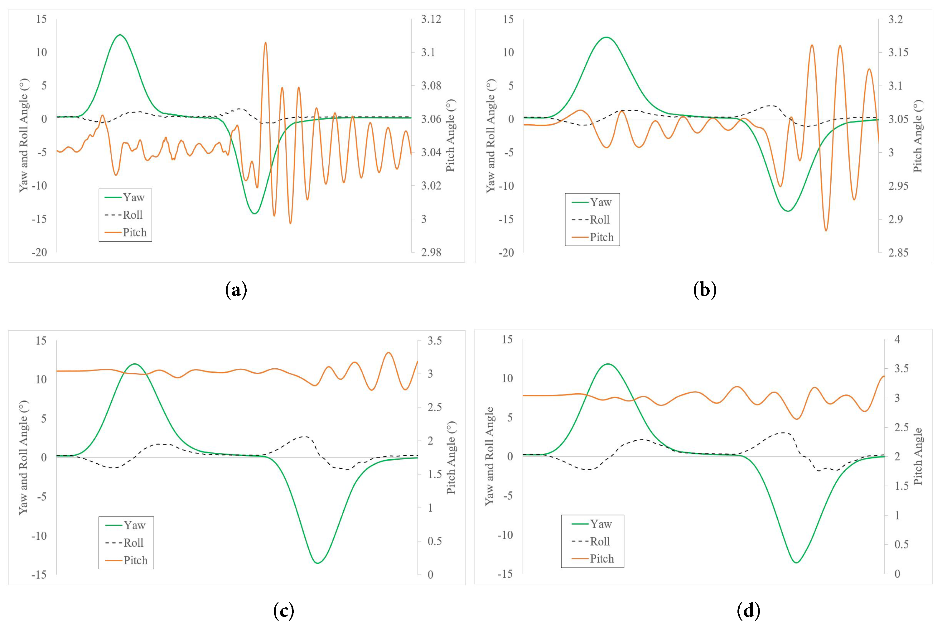
The parameters used to train the network are velocity, longitudinal acceleration, lateral acceleration, yaw angle, yaw rate, yaw acceleration, pitch angle, pitch rate, roll angle, roll rate, engine speed, steering rack travel, steering wheel angle, slip ratio, normal forces, and the relationships of the angles during the maneuver, shown in
Figure 7. The output is the side slip angle. The inputs contribute to stabilizing the vehicle on different maneuvers, preventing the loss of vehicle control. This type of maneuver is necessary to overtake a vehicle and return to the same lane to avoid impacting a vehicle that abruptly decreases its speed, through which a person, another vehicle, or an animal passes.
4. Results and Discussion
Artificial intelligence through neural networks can be applied to dynamic phenomena, such as the response of a vehicle considering different driving conditions. These phenomena are nonlinear not only because of the interrelationship of the different components and events, but also when considering indirect effects such as sudden braking or crossing a pedestrian or an obstacle. This maneuver generates the need for a lane change; having two lanes in the opposite direction adds one more maneuver to return to the same lane, concluding a double lane change.
Any maneuver can affect the lateral dynamics of a vehicle because lateral forces are generated at the point of contact between the wheels and the pavement; this is transmitted through the suspension system to the body, also depending on the characteristics of stiffness, which, if low, is presented with a delay. The driver perceives this and can be attenuated with assistance systems as it can cause the vehicle to generate moments around the center of mass, as shown in
Figure 1.
Although the synthesized virtual tracks simplify and reproduce driving on the road, it is necessary to represent all the conditions to include the variables. In this work, we have measured the vehicle’s response under a double lane-change maneuver.
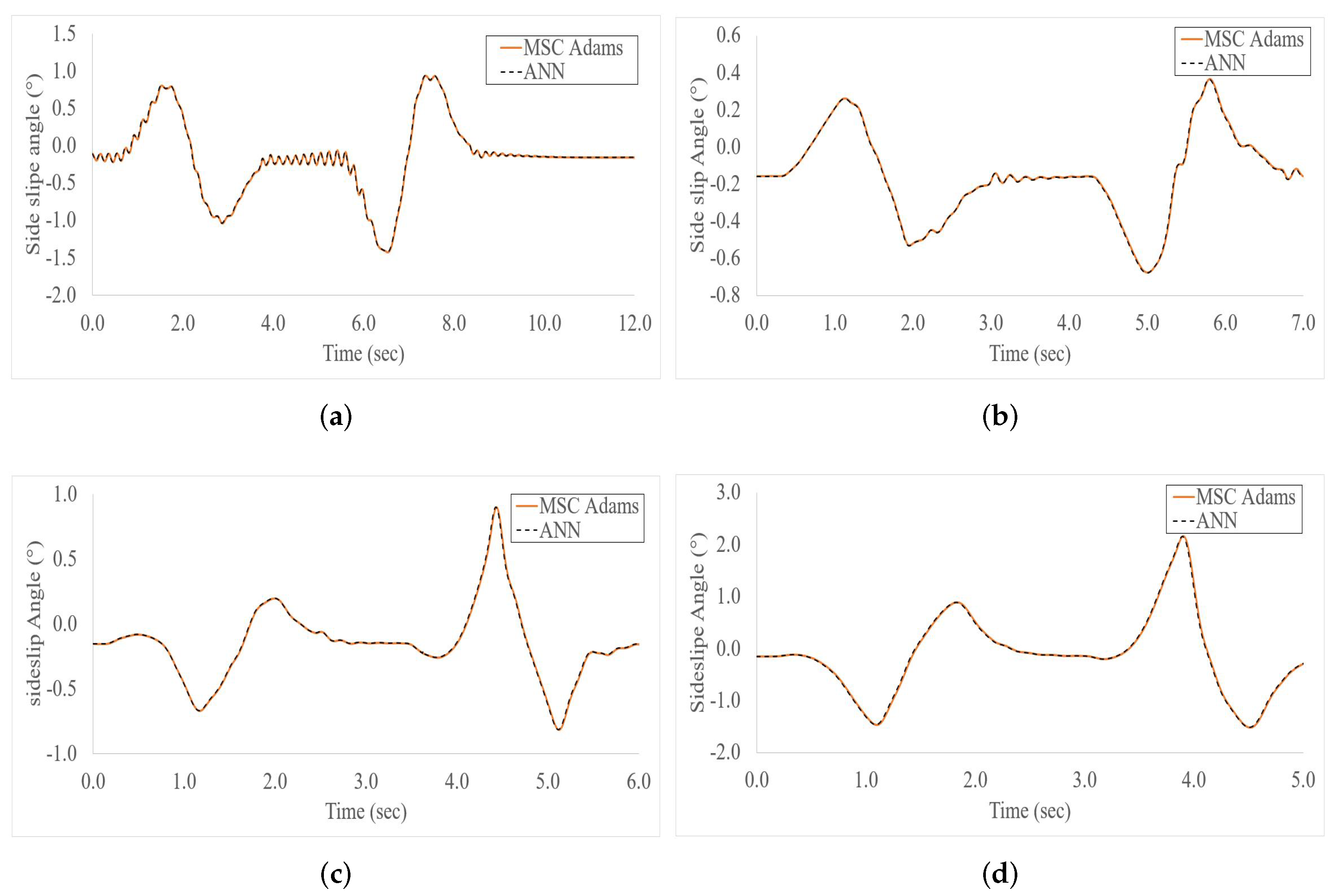
Based on the responses of the kinematic simulation, together with the characteristics of the electric vehicle, synthesized signals were added through the vehicle’s response to include the traction forces that are a function of the normal forces. By controlling the slip rate, it is possible to reduce the risk of sliding conditions. These results, taken together, suggest that it is possible to predict the slip ratio at double lane change using ANN. The average error is < to 1% at velocities of 40, 50, 60, and 70 km/h.
5. Conclusions
This study uses an ANN based on vehicle responses and synthetic data to propose a slip ratio at double lane change. Lane change is a fundamental aspect of vehicle driving, having an effect on the one hand on active safety comfort, and through ADAS, this information can be used to communicate with other vehicles, for example, in a simultaneous or sequential lane change, or a combination of a series of vehicles, with the nearest one changing lanes, while the one coming behind does the braking, avoiding collisions. The double lane change is simulated using MSC Adams Car. Changes in vehicle dynamics due to lane change can be predicted by the responses of the same vehicle, as well as by responses synthesized according to its behavior. With these signals, it is possible to predict the slip ratio using neural networks with an average error of 0.0485%, 0.0198%, 0.0123%, and 0.0170% at velocities 40, 50, 60 and 70 km/h, respectively.
Although this study focuses on slip ratio at double lane change prediction in a double lane change, the findings may well have a bearing on extending to another maneuver.
The integration of kinematic simulation using MSC Adams Car will allow the virtual development of new platforms integrating the dynamic responses of the vehicle in dual lane change. This will allow the analysis at the early stages of the development of the adjustment of sensors and assistance to improve maneuverability but also have an impact on the safety of occupants and pedestrians by reducing collisions.
The proposed methodology can be used at the early stages of design where virtual models are available, and preseries vehicles due to the responses can be obtained by instrumentation with transducers as accelerometers and linear variable differential transformers to measure displacement and, in another way, signals obtained by the vehicle sensors. Predicting and controlling under extreme driving conditions, such as double lane changes, increase the vehicle’s active safety.


 ,
, 


