1. Introduction
During recent decades, global warming, reduction in petroleum resources, deterioration of air quality, and the different inquiries regarding a pollution-free healthy and clean environment have heightened scientists’ regard for producing alternative sustainable and environmentally clean solutions. In developing countries, especially in large cities, the transportation sector is one of the main causes of increasing harmful exhaust emissions in the environment (i.e., pollutants, such as Particulate Matter (PM), nitrogen oxides (NOX), CO, and sulfur dioxide (SO
2)), causing many health troubles. The electrification of vehicle powertrains is widely seen as a viable way to increase fuel efficiency and reduce greenhouse gas emissions in the automotive sector [
1].
The electric force is the primary source of energy for electric vehicle technology. It is stored in a storage system, often hybrid, and is converted by the motor into mechanical energy and then transformed on the vehicle wheels using the best possible transmission device, which must be characterized by high efficiency, provide the required torque and speed for the wheels, and be reversible. The most common transmission system for the electric powertrain is the single-speed gear ratio. The electric motor should give the vital power to propel the electric vehicle in an efficient way. The choice of an electric motor for an electric vehicle (EV) chassis is a significant challenge. There are various electric vehicles available on the market [
2]. These vehicles incorporate different motors for different functionalities. EVs may be equipped with alternative current (AC) motors or direct current (DC) motors according to configuration or relying upon the expected utilization. Several studies have been conducted on the aspect of electric motors, and distinctive kinds have been created [
3]. This provides electric vehicle producers with a wide assortment of electric motors to browse according to their needs. The determination of a specific type of electric vehicle motor should be done with caution, as the qualities of the motor influence the overall performance of a vehicle [
4].
Many criteria, for example, efficiency, cost, reliability, innovation, and controllability, must be considered. From the point of view of industrial applications, for electric vehicle application and more, factors must be taken into account; the most widely recognized motors used in electric vehicles are permanent magnet synchronous motors, induction motors, and brushless DC motors [
5,
6]. The traction motor candidates for the electric traction system must meet high-performance, speed sensorless control as a low-cost solution and must be reliable, efficient, and offer an outstretched point of stability at different speeds [
7]. Many reviews reported the recent technologies and challenges of electric and hybrid vehicles [
1,
3] covering the numerous aspects and discussing the challenges and opportunities to be considered in developing new electric vehicles. This paper focuses on electric motors and their interactions and presents the recent trends in electric motors available on the market. In addition, it presents a multi-criteria comparative study of electrical motors used in electric vehicles. In the first section, the different electric vehicle architectures and the components of the electric powertrain are introduced. The second section concerns the literature study of the motors used in electric vehicles. Then, a comparative analysis of the different electrical motors is performed based on various criteria that impact numerous aspects, mainly the energy efficiency, electrical characteristics, robustness, and maintenance factors. Conclusions are then made to identify the potential candidate electric motor for the electric traction system.
2. Electric Traction System
The architecture of the electric vehicle alludes to the disposition of the energy storage system and the components of the electric powertrain. The architecture of the EV is more flexible than a conventional internal combustion engine (ICE) vehicle’s architecture due to the reduction of the moving parts; the clutch and the conventional transmission system are substituted by a simple gear ratio, in addition to the simplification of the ICE system [
8].
2.1. Electrical Vehicle Powertrain Architecture
The energy flow in EVs is achieved with flexible electrical cabling and the minimum of moving mechanical linkages.
Figure 1 shows the detailed basic configuration of an electric traction system. The principal constituents of an electric powertrain are the power source, the electronic controllers, the electric motor, the transmission system, and the onboard charger for batteries. The secondary power supply of electric vehicles provides the power required for all auxiliary systems, mainly the temperature control units that monitor the favorable temperature of the battery system for its long-running time and the power steering units [
9].
2.1.1. Charging System
Electric cars can be recharged by alternative or continuous current in respective normal charging or fast charging. At home, we are dealing with an alternating current that will have to pass through an on-board charger; this is what limits the recharging capacity because the internal rectifier cannot have a large capacity, and this is limited to a little more than 20 kW for the best-equipped cars—in general, it is around the 10 kW limit for a good electrical installation that allows going up to this level. Basically, a conventional outlet delivers 2.7 kW although the car can take more. Superchargers are direct current and do not need to go through an internal converter in the car; the recharging capacity can then be enormous, exceeding 250 kW [
10,
11].
2.1.2. Energy Sources
The main families of direct electrical storage systems are the accumulators that store energy in chemical form and the supercapacitors that store energy in electrostatic form. In electric traction systems, the concept of hybrid energy storage systems is introduced to compensate for the limits related to each storage system; the hybrid energy storage system (HESS) is composed of batteries, supercapacitors, and full cells. The supercapacitors are utilized to provide optimum performance in transient regimes. A summary of the performance of technological variants of energy storage systems and energy sources are presented in the Ragone diagram in
Figure 2.
The batteries are classed as primary, secondary rechargeable, mechanical replacement, reserve, and thermal. The charge transfer between the cathode and anode in Li-ion battery cells is carried out by lithium ions in the electrolyte; a Li-ion battery has no metallic Li. Therefore, commercial production cathode materials include LiCoO
2, Li(NiCoMn)O
2 (NMC), LiMn
2O
4 (LMO), and LiFePO
4 (LFP). Graphite is currently the most used anode material. Researchers have been working on groupings of electrode materials that can deliver higher voltage and higher capacity in their continual hunt for more power and capacity. Silicon (Si) alloys are intensively pursued for the anode, with the objective of addressing material stability and cycle life concerns. Higher voltage phosphates such as LiMnPO
4 and LiCoPO
4, as well as high-voltage spinel, LiMnxNi
2−xO
4, are of research interest in the realm of advanced cathode materials for improved material stability and cyclability [
12].
2.1.3. Power Electronic Units
The power electronic integration in the EV is a cost-effective solution. It plays the role of support to transfer and adapt energy between the energy storage system and the drive motor. The power conveyed by the battery should guarantee the ability of the electric motor to start the vehicle, as defined by the algorithms dedicated to the control system, which is defined for each type of motor to ensure its operation at the ultimate efficiency, usually between 95% and 98%. There are various control strategies accurately applied to EV traction systems such as Adaptive Model Reference Control. Neural networks and fuzzy logic are used with promising applications to realize the concept of intelligent controllers. The power electronic components must be conditioned to both high temperatures and high vibration levels [
9].
Figure 3 presents the principal component in the electric powertrain system, namely, the DC/DC converter, the DC/AC inverter, the on-board charger, and other auxiliary converters that serve to adapt the energy to power the several loads in the EV, the control units used to manage the energy flow between the electric powertrain components.
2.1.4. Transmission
The motor is characterized by a very high operating range (16,000 rpm on a Tesla Model S for example) and torque quickly available at low revs, which eliminate the necessity of a gearbox. A gear ratio reductor with single speed or at most dual speed is commonly utilized. It should be mentioned that it is an important element to be considered while studying the electric motor in the powertrain; on a Tesla Model S, the reduction ratio is approximately 10:1, and it is generally provided by an epicycloidal gear train, which is mainly used in automatic gearboxes.
2.1.5. Electric Motors
Electrical machines are utilized to transform electrical energy into mechanical energy and vice versa and to provide torque and power to the driveline of the EV. The energy conversion efficiency of an electric machine is between 80 and 96% [
9]. The electric motor provides high torque and high power density with better torque characteristics at the starting phase, with an imminent rated power that is two or three times higher than the rated power of the conventional ICE, and it is utilized in regenerative mode when braking and decelerating for charging the storage system [
9].
2.2. Pure electric Vehicle Architecture
An electric vehicle uses only electric power in the traction system. There are different EV architectures that are achievable due to variations in the arrangement of the components of the electric drivetrain. In this work, the presented architectures are only for pure electric vehicles.
The components of the electric powertrain are the motor (M), differential (D), gearbox (GB) with a clutch (C) or a fixed gear (FG).
Figure 4 presents the different EV architectures; they are similar for battery electric vehicles (BEVs) and fuel cells electric vehicles (FCEVs). Fuel cells can be either the primary or secondary energy source, depending on the requirements [
7].
Figure 4a shows an electric architecture that includes an electric motor, a clutch, a gearbox, and a differential. This architectural configuration was primarily used in the conversion of ICE vehicles to electric vehicles using the existing components. In
Figure 4b, the clutch has been removed and replaced by the gearbox with a fixed gear architecture; hence, the weight of the powertrain is reduced in this configuration.
The most preferred architecture by EV manufacturers in modern models is shown in
Figure 4c; it includes one electric motor with a fixed gear and a differential integrated into a single assembly.
Figure 4d presents an architecture with a dual-motor configuration in which the differential action can be provided by the two motors; the wheels are individually actuated by two electric motors separated via a fixed gear. They can operate at different speeds and provide the differential features.
Figure 4e presents a called in-wheel drive configuration; this architecture incorporates a fixed epicyclic gearing system to reduce the output speed of the motor to the appropriate speed. It offers the advantages of a high speed reduction ratio with an in-line arrangement of input and output shafts; the compact propulsion system requirement eliminates the use of reduction gears and mechanical differential in the driveline by placing a direct drive motor in the exact location where torque is required [
9].
The arrangement of the direct drive motors as shown in
Figure 4f for electric vehicles simplifies the mechanical layout, reduces the number of driveline components, energy loss in transmission, maintenance, and weight, and improves the overall reliability and efficiency of the system. This gearless wheel motor drive system is used for high-torque and low-speed applications [
14,
15].
The configuration of the mentioned architecture depends on the required size and the application of the electric vehicles; many parameters are considered, essentially, the performance, the compactness, the weight, and the cost of the EV. Nowadays, the popular configuration is the one presented in
Figure 4c; it has been broadly used in current electric vehicles for training both wheels by using only a single motor, and the one in
Figure 4b is in second place.
The Chevrolet Spark, Nissan Leaf, Kona and Ioniq from Hyundai, and Niro from Kia use a front-wheel drive system. However, EVs can have a rear-wheel drive framework with a similar arrangement to the front wheel drive; the Tesla Model S, BYD E6, Reva, and E20 sport from Mahindra utilize rear-wheel drive with a single-speed transmission reducer [
9].
Figure 5 shows an all-wheel drive (AWD) architecture with an in-wheel motor (M) and reductor (R) system. The AWD uses two motors to drive the front axles and two motors to drive the rear axles; it provides better traction control and prevents slipping when driving in harsh conditions. Torque orientation can be used for better cornering and efficient driving performance [
9].
3. Electric Traction Motors
The electrical machine and the power inverter are combined in a single unit to form the core unit in electric vehicles.
3.1. Essential Characteristics of EV Traction Motors
An EV traction motor must meet different types of operating criteria than those used in industries. In industries, most loads are constant and classified, while on the road, the EV may need to change speed, increase torque on slopes, and abruptly apply brakes.
Figure 6 shows a typical load profile that is intended for a traction motor [
4]. It is imperative to note that the motor exceptionally or rarely follows the torque–speed curve during operation. These curves can be viewed as circling all load points. The full load cycle can be divided into three sections depending on the speed, as shown in the graph of
Figure 6.
The main characteristics required for electrical machines for traction purposes include quick and rapid torque response with important power density at low speeds for starting and scaling, as well as consistent power at higher speed, high efficiency over the wide range of speeds with constant torque and constant power, overload capacity, usually twice the rated engine torque for short durations, small size, reduced weight, a lower moment of inertia, acceptable cost, as well as high reliability and robustness. For different operating conditions of the vehicle, the fault tolerance ability has to be considered [
16].
The choice of an electric vehicle motor depends on the conditions outlined by the variables as presented in
Figure 7 that are the mission of the vehicle, the restriction of the vehicle, and power source variables. The vehicle restriction includes the vehicle type, vehicle weight, payload, and battery weight. The vehicle requirement variables are defined by a drive cycle. Considering the aforementioned variables and the characteristics that the motor meets, the performance requirements of the electric vehicle can be chosen [
9].
3.2. Motor Drive Types
The electric machines integrated in electric vehicles must meet the specific characterization discussed above, especially a high efficiency, a high rated torque, a wide high-speed range coupled with constant power, a high starting torque, high power at cruising speeds, high specific power and power density, high overload capability, fast dynamic response, good flux weakening capacity at high speed, a good fault tolerance characteristic, and high reliability. These requirements are crucial for the various machine types, in addition to the cost that must be acceptable and competitive in the market [
17].
Figure 8 presents the potential motor types and possible choices for EV applications. The basic types of machines used in electric vehicles (EVs) are induction machines, permanent magnet synchronous machines (PMSMs), switched reluctance machines, synchronous reluctance machines, and direct current machines. In the latest vehicles, four classes of motors have been adopted: IMs, synchronous machines, PMs, and reluctance machines.
Different machine configurations have been utilized or are likely motors to be used, including the conventional radial flux machines in addition to the axial and transverse flux machines.
3.2.1. Permanent Magnet Synchronous (PMS) Motors
When it comes to vital productivity, the most efficient motor is the permanent magnet (PM) brushless motor, followed by an induction motor with relatively comparable efficiency. In fact, many vehicle manufacturers (for example, Nissan, Honda, and Toyota) have actually used these motors. These motors have a higher power thickness and a higher competence, as well as being more powerful in heat diffusion [
18]. The machine takes advantage of the high energy density of the magnets, on the grounds that the stirring of the permanent magnet requires limited space. As no excitation current is required, the PMSM gives immense proficiency in the field of ostensible speed. The dominant losses in the context of PMSM are the iron losses, which occur in the stator and can be effectively reduced by a cooling system. PMSM outperforms IM in terms of control and productivity. Its major obstacle is the high cost of rare earth magnets such as NdFeB. Another weakness is the extra current segment needed to debilitate the field, through which higher stator losses occur and productivity decreases at high speed [
19,
20].
3.2.2. Induction Motors
Due to their low cost and robustness, induction motors are the most commonly utilized machines in industrial applications including electric traction.
Induction motors are generally used in electric vehicles due to their important proficiency, excellent speed control, and the absence of commutation. An Induction Motor Drive is ideally used in EV. They are generally recognized these days since they are the least dialed switch. This explains their high reliability and maintenance-free tasks [
21].
Induction motors are typically operated with a vector-control drive, which enables a wide speed range variation. Induction machines are characterized by three distinct operational regions, as shown in
Figure 9, a constant torque region, constant power region, and when reaching high speed, reduced power regions; these characteristics are determined by the machine design, power electronics, and control [
7,
17]. It can be clearly seen that the typical speed-torque and power characteristics are similar to the requirements of the electrical traction system.
3.2.3. Permanent Magnet Brushless DC Motors
The advantage of PMBLDC motors is their ability to deliver higher torque, at a similar amount of current and voltage, compared to other motors. As these have high power and much greater productivity, magnetic brushless DC motors have a decent ability to be used in the EV pulse setting [
5]. The disadvantages of the PMBLDC motor are the expensive magnet used in the rotor. It is difficult to build large torque into the motor due to the mechanical strength of the magnet. In addition, the weakening capacity of the field is limited due to the presence of a permanent magnetic field. The operation of the constant power region can only be extended by advancing the switching angle [
22].
3.2.4. Switched Reluctance Motors (SRM)
Switched reluctance machines (SRMs) use rotor position switches to energize the phase windings separated in sequence. The extension of high speed is conceivable. The rotor aims to proceed to a place of least reluctance, thus inducing torque. SRMs possess qualities, namely, a large starting torque and great adaptation to non-critical failure capability, thus being reasonable for EV use. The steady-state activity is conceivably shaped by the phase progression of current in the conduction edge of the stator to the point where the coverage between the progressive phases occurs [
5]. The SRM rotor is very simple as it does not consist of any windings or brushes or commutators or magnets. Due to its simple construction and low inertia ratio, this motor consists of high speed operation and rapid acceleration; the main disadvantages of SRM are the torque ripple and noise [
22].
3.2.5. Direct Current Motors
Excursion motors for electric vehicles are divided into two sections, switching motors and non-switching motors. Switch motors are essentially conventional DC motors, including series and shunt excitations. DC motors have long been the subject of interest due to the simple control and decoupling of motion and torque. DC motors are still great candidates for low-power applications. DC brush motors can achieve high torque at low speed, making them suitable for traction frame. However, low power density, relatively high maintenance and commutations are the disadvantages of brushed DC motors, making them unfit for standard electric vehicle application. On the contrary, brushless DC motors offer better efficiency and require less maintenance [
23]. The DC (direct current) drive has been used evidently in EVs due to the fact that it offers perfect speed control and torque requirements.
4. State of Art
4.1. Recent Trends of Electric Machines for Electric Vehicles
4.1.1. Traction Machines with Rare-Earth Magnets
The ability of the permanent magnet-based machines to develop permanent magnet torque and reluctance torque and to achieve a wide high constant power speed range operations has increased their appeal for traction drive systems, with their much-improved magnetic properties when compared to non-rare-earth based magnets, which make it possible to achieve the desired performance. The rare-earth magnets are equivalent magnetically to very high current coils (of the order of 1 kA per mm magnet thickness) with no loss according to [
24]. The rare earth magnetic materials, especially neodymium iron boron, form the basis for the traction motors used in many of today’s leading electric vehicles. These magnets enable the design of motors that offer extremely high torque densities, making them compact and lightweight, whilst also offering high efficiencies. However, there are several arguments that this technology may not offer the best long-term solution for use in this application. Rare earth magnets are expensive, doubling or more the raw material cost of the electric motor. NdFeB motors may also not be as efficient during normal vehicle operating conditions as the headline claims may indicate, with control strategies needed to weaken the influence of the magnets, allowing higher speed operation, but being a source of inefficiency [
5].
According to [
25], the cross-cutting pillars of sustainability, environmental, economic, social, and technical fields have differing conclusions regarding the use of permanent rare earth magnet motors in the EV industry, which shows the need for the automobile industry to come up with strict guidelines using a full life cycle assessment [
25].
4.1.2. Traction Machines without Rare-Earth Magnets
A major trend in the design of machines for EVs is the parallel efforts toward non-rare earth machine alternatives. By eliminating rare-earth magnets, not only is the motor cost reduced, but the dependence on this critical material is removed. Induction machines (IMs), synchronous reluctance machines (SynRMs), and switched reluctance machines (SRMs) have had a good shot at meeting this need. The increasing demands on high specific power and power density requirements are eliminating IMs as viable options Both SynRMs and SRMs have a simple construction of a rotor composed of only thin steel laminations; SRMs are characterized by consequential noise along with an important torque ripple and vibration, in addition to high complexity and expense in the controls. SynRMs are also attractive in terms of strength, high efficiency, low torque ripple, and simplicity of control but represent a crucial disadvantage such as a lower power factor that impacts converter sizing and cost and more importantly, they have a limited constant power-speed range. If meticulously designed, SynRMs with no magnets can be very interesting and tempting low-cost machines for both motor and inverter aspects. It seems that with more specific and aimed research, SynRMs and SRMs can afford a path to gain high performance traction machines without rare earth minerals.
In the paper [
26], the authors investigated alternatives to replace rare-earth PM motors employed in direct drive applications. The proposed motors were a surfaced PM (SPM) motor with non-rare-earth PM, ferrite PM (Fe-PM), a spoke type motor with Fe-PM, a synchronous reluctance motor (SynRM), and a PM-assisted SynRM (PMaSynRM). The analyzed results of each motor were compared with the results of the reference motor. In particular, the demagnetization phenomenon of the motors with Fe-PM was analyzed since the Fe-PM is easily demagnetized by the reversed flux. Overall, this paper suggests the pros and cons of each alternative to substitute rare-earth PM motors.
The new trends are about to substitute the permanent magnet in PMSM with a wound rotor. To keep with the advantage of the synchronous machines, the most innovative solution is the one designed by the Mahle company, and among the most powerful wound synchronous motors are the fifth generation designed and integrated by BMW in iX M60, iX xDrive 40, and iX xDrive 50 [
27].
4.1.3. Machine Integration and Thermal Management Systems
Machine and power converter integration is another growing tendency that will keep increasing. As space requirements for vehicular comfort increase, powertrain devices must become more compact, and innovative integration techniques consequently become more important. The EV motor’s internal temperature significantly influences its torque/power capabilities. The dominant heat sources are located within the electric motor stator windings and create ‘hot spots’. To keep the motor functioning properly without exceeding the established temperature limits, thermal management design for electric vehicles is very important in order to manage the thermal energy dissipated by the hot spot of the motor and the other operating components [
28].
The idea of assembling the electric machine and power electronic drive into one unit affords compactness, lowered volume, ease of installation, fewer parts, and shortened cable runs and busbars. These are considered to be attractive technical benefits along with reduced electromagnetic interference and reduced voltage overshoots on motor drive terminal in addition to important expense reductions. It is estimated that integrated motor and power converters can reach 10–20% improvement in power density and a 30–40% decrease in manufacturing and installation expenses [
29].
Figure 10 shows the four major types of inverter and motor integration techniques that exist in the literature as presented by [
29]. The techniques comprise radial and axial mounting approaches that consist of mounting the inverter on either the motor housing or on the stator. In
Figure 10a, the inverter is anchored on top of the housing of the motor while it is mounted on the end shield of the motor in
Figure 10c. In
Figure 10b, the power converter is mounted on the periphery of the motor stator, while it is fastened to the end of the stator in
Figure 10d. Each of these mounting techniques is characterized by benefits and drawbacks that are presented by [
29]. The most frequent way shown in
Figure 10a provides a simple implementation; however, it represents some limitations when it comes to reaching high power density. In this technique, the inverter package is placed on the housing of the motor or even on the side of the housing. Furthermore, a shared or separate cooling system for the motor and drive can be used. Sometimes the cooling system is separate, which leads to sub-optimal utilization of the system volume. The other approaches where the power converters are fitted to the stator periphery lead to a better integration; however, due to stator curvature, they do not easily provide a smooth area to fit electronic elements. The mounting configuration and the level of integration will be dependent on the configuration of the vehicle, including the number of motors and axles.
In order to constantly improve the power density and specific power of vehicular traction drive systems, advanced thermal management systems are needed. The authors in [
30] presented a detailed survey that focused on cooling techniques and their computational methods. The paper offered a complete summary of the convection techniques used in automotive traction motors with their benefits, drawbacks, and necessities for optimizing cooling performance for the various techniques discussed, in addition to highlighting the cooling methods used in the traction motors of recent vehicles.
Figure 11 represents thermal management systems and interconnections applied for cooling power train components and batteries in recent vehicles [
31].
Active cooling with water glycol is common for various drive trains and except the Chevy Spark that uses active oil cooling. It must be noted that there are different levels of integration and correspondingly different interconnections between components. For example, in the Tesla, the cooling is interconnected between all drive train components and the battery. We also see a tighter integration in the second generation of the Nissan.
Leaf compared to the first. Considering the examples provided by the Tesla and the 2017 Leaf, Chevy Spark and Bolt have standalone battery heating and cooling, and BMW has combined heating and cooling of the battery with the air-conditioning. It is obviously expected that most of these vehicles will follow a tighter integration with a common thermal management system interconnecting the whole drivetrain elements, which consequently should be monitored in a permanent way using various methods such as cooler prospection based on thermal imaging [
32].
Many studies are still devoted to develop and optimize the thermal management system. To keep the motor functioning properly without exceeding the established temperature limits, a new cooling concept for PM motors based on a nonlinear tracking controller to govern the cooling system operation was proposed by [
33]. As a result, the stator hot-spot temperature of the tested motor was stabilized with an average error of 0.13 °C and a 68% power consumption reduction when compared to classical control. The authors in [
34] investigated the design optimization of a thermal management system for battery modules, controllers, and electric motors in EVs. A combination of passive and active cooling systems was proposed. The Design Failure Mode and Effect Analysis method has been deployed to identify the potential failure modes and causes so that improvements can be made for battery modules, controllers, and electric motors. The material selection process for the designs was based on the analysis using Cambridge Engineering Selector. It was found that the best material for the electric motor and controller water jacket is aluminum alloy 6060 while air cooled ducting used high-density polyethylene, and battery housing used polycyclohexylenedimethylene terephthalate.
4.2. Features of Electric Motors for Electric Vehicles
4.2.1. Power Density
Motor power density is a crucial variable when it comes to electric traction and aircraft vehicles. Various designs to improve this characteristic in different motors is discussed in the paper [
35]. One can notice that motor power density has reached 0.5 kW/kg to 2 kW/kg for hybrid electric vehicle applications [
36]. The paper [
37] presents a solution to improve the power density of electric motors used in electric or hybrid cars using a dual motor with a planetary transmission system. By increasing the power density, a reduced amount of raw materials is required, and consequently, electric motors are more cost efficient. To achieve higher power densities, a new winding type is suggested; contrary to actual distributive windings, a fully automatic production process is possible since winding bars can be inserted in the stator slots automatically. With these bars, the freedom of designing the winding is increased [
38]. This offers new possibilities to increase the power density of electric motors. One key factor to increase the power density is to improve the thermal conductivity of the winding. Premanufactured winding bars significantly increase the winding design freedom since the production process allows an unrestricted placement of single conductors that is not possible with the conventional approach. In this paper, the influence on the thermal conductivity of one promising bar design, namely, the use of twisted wires, is investigated [
39].
4.2.2. Dynamic Response
The authors in [
40] present some of the most common traction solutions used for electric vehicles adopted by different car manufacturers, covering the dynamic response of the most used electric machines applied in EV. The paper describes the behavior of three types of electric machines used nowadays in electric commercial vehicles: a brushed direct current machine (DC), a brushless machine (BLDC), and an induction machine (IM). The brushed DC machine presents the important disadvantage related to its maintenance cost. The need for brush changes after a certain period makes this very costly. Brushless machines do not have this maintenance cost-related problem [
41]. For the induction machine, the cost of production and maintenance is the lowest among the three analyzed machines. Consequently, this type of electric machine is more suitable to be used than brushed or brushless DC machines. To compare these types of machines, they developed a testing regime based on the experience of a driver facing all functional situations. They took into consideration the rapid and slow start-stop regime, speed change regime, and the backward movement of the vehicle and studied the behavior of the three types of machines using these testing regimes. Despite their advantages and disadvantages of one versus the others, these types of electric machines are all used nowadays in the prototypes and commercial EV/HEVs.
The paper [
42] presents the modeling of PMBLDCM (Permanent Magnet Brushless DC Motor) with the load characteristics of an urban city electric car. The dynamic responses of torque and speed of the motor in the constant torque region are discussed Tests carried out using Matlab/Simulink in an attempt to obtain data describe the dynamic responses of the motors that drive electric cars in cities.
Electric vehicle drive systems require fast torque response and high efficiency over a wide range of velocities. In the paper [
43], a fast torque response control strategy suitable for the region above the base frequency is proposed based on an analysis of the impact of the efficiency optimization strategy on the dynamic response. The operation characteristics of induction motors in typical drive cycles are analyzed, and then an efficiency optimization strategy based on the loss model and its corresponding fast torque response control strategy is proposed. The efficiency optimization strategy improves the motor efficiency at a steady state, and the fast torque response control strategy distributes magnetizing current and torque current according to the voltage limit offset to achieve maximum torque output in the dynamic process. The strategy breaks through the limitation of traditional maximum torque control strategies based on the steady state analysis. The simulation and experimental results indicate that the proposed control strategy can provide fast torque responses above the base frequency in dynamic processes and reduce the impact on the electric vehicle dynamic response caused by the efficiency optimization strategy.
4.2.3. Noise Level
The importance of the vibration and dynamics of electric vehicle drivetrains has increased because of noise and durability concerns. In study [
44], the important dynamic responses of drivetrains, including the dynamic mesh force acting on the gear teeth, dynamic loads acting on the bearings, and torsional fluctuation of the tire or load under major vibration excitations, such as motor torque fluctuation excitation and spiral bevel gear mesh excitation, were investigated. The results demonstrated that at a lower motor speed, dynamic responses such as the dynamic mesh force, dynamic bearing loads, and dynamic torsional displacement of the tire or load under motor torque fluctuation were dominant. At a higher motor speed, however, the dynamic responses under the gear mesh excitation were dominant. In addition, increasing the pinion-motor torsional compliance was an effective approach for suppressing the dynamic responses of drivetrains under motor torque fluctuation [
45].
The mounting of power converters on electric machines to form one compact package comes with critical challenges for the resulting system. One crucial difficulty consists of complex and augmented thermal management problems of the whole system. An additional problem consists of the motor’s vibration: motors are more tolerant to vibration and harshness than electronic boards that are delicate and less tolerant to vibrations. Therefore, combining these two components in one package comes with other new and various challenges and issues. To solve these difficulties, many studies have been conducted in order to come up with practical and creative solutions in order to maximize the benefits of such systems and reduce the rate of their drawbacks and problems [
46].
4.2.4. Torque Ripple
As widely known, a large torque ripple is a severe problem because it can cause severe noise vibration, reducing the riding comfort. In addition, a large source current ripple can appear in the power supply to the inverter that drives the traction motor. This source of current ripple is also another severe problem because large AC current may flow from the main battery, thus decreasing the battery lifespan. The authors in [
47] propose an experiment with a current tracking control technique based on a pre-computed current profile of SRMs for vehicular propulsion by eliminating the source current ripple as well as the torque ripple. In the same context of control, the authors in [
48] present the application of resonant control (RC) to suppress the impact of the PM torque ripple, which aims to reduce the vibration of a vehicle. The paper [
49] presents a torque ripple minimization control strategy for an inter-turn short-circuit (ITSC) fault based on the open-winding (OW) five-phase fault-tolerant fractional slot-concentrated winding interior permanent magnet (FTFSCW-IPM) motor drive system with common DC bus.
4.2.5. Robustness
The robustness of a motor system refers to the perturbation of its state variables or internal parameters and the ability of the motor system to maintain its fitness in performing a task in the presence of the perturbation. Evaluating the robustness of a system requires a measure of task-specific fitness. Given such a measure, we can quantify the robustness of a motor system by introducing a perturbation and comparing the performance of the perturbed system to that of the unperturbed system. A more robust system will exhibit a less dramatic degradation in performance in response to the perturbation than a system that is less robust [
50]. There is increasing attention placed on electric motors without PM and with less winding and mechanical commutation, such as SRMs. Due to their strong construction and low cost, SRMs are considered physically powerful candidates for EVs [
51]. SRMs have gained popular recognition in the EV market due to high power density, easy construction, low cost, rigid design, fault tolerance, torque ripple control, vibration control, and noise, and based on these properties of the special electric motors, in [
52], special aspects of the BLDC motors, PMSM, and SRM-based drive systems for EVs are presented and reviewed, and the reasons for substitutions of permanent magnet motors with SRM for EV applications are explained.
4.2.6. Overload Capacity
Electrical overload is caused by the excess of current passing through the motor’s windings that breaks the limits of the rated current that the windings can bear and carry safely and efficiently. This phenomenon is triggered by a low voltage supply that makes the motor draw an excessive amount of current in order to maintain its torque. Other incidents that can cause such an issue consist of excessive voltage supply and short circuits [
53].
4.2.7. Fault Tolerance
The electric vehicle drive system is a multi-variable function, with a complex running environment and changeable system, so its failure form is complicated. Due to the long running, environmental factors, and improper manufacturing operation as well as other reasons, the electric drive system may have various problems, and any failure could further expand, thereby affecting the safe operation of the vehicle. Therefore, timely, reliable, and fast detection of the failure and an appropriate fault tolerance strategy to maintain the basic operation of electric vehicles are valued, especially for personal cars. The authors in [
54] proposed a new fault-tolerant rotor permanent magnet flux-switching (FT-RPMFS) motor. The key point is its new rotor topology with the unique configuration of the auxiliary PM (APM), located in the rotor to enhance the air-gap flux density. The authors in [
55] mentioned that the probability of motor failure is greater compared with that of the single motor drive, and without proper control, the motor failure can lead to dangerous situations such as off tracking and violent spinning of the vehicle. The authors in [
56] demonstrated an important correlation between the vibrations and the electrical signals, which offers a great opportunity to minimize and predict the risks, especially thorough artificial intelligence.
4.2.8. Life Expectancy
In contrast to conventional motors, electrical motors have additional aging characteristics or aging design aspects. Motor aging factors can be grouped into four classes that describe mechanical, electrical, environmental, and thermal aspects. For instance, mechanical wear and fatigue of the bearings are the main cause of failures of mains-operated standard motors [
57]. Depending on the applied load, mechanical stresses also cause broken rotor bars in induction machines. Modern frequency converter-driven motors face additional electrical aging effects such as bearing currents and high electrical stresses on the motor insulation due to voltage peaks at the motor terminal or within the motor coils [
58]. Humidity, grease, or salts in the motor or external vibration are environmental effects that lead to degradation and aging of the insulation system. For this reason, many traction motors for cars are constructed using resin-casting technologies that help to protect rotor and stator winding from environmental factors and provide more mechanical stability [
59]. The life expectancy of an electric car motor is difficult to predict since it is dependent on so many variables. It has been suggested that the optimum lifetime under ideal settings is approximately 15–20 years [
60].
4.2.9. Development Maturity of the Motors
According to [
61], many studies are being conducted in order to advance motors in hybrid and plug-in electric vehicles, with a particular focus on decreasing the dependency rate of using rare earth materials that are mandatory for permanent magnet-based motors. As an ultimate objective, these studies aim to reduce electric motors’ price and expenses, size, and weight while keeping or boosting performance, efficiency, and reliability. To meet 2022 price targets, research must reduce the cost of the motor by 50%. Many efforts are devoted for this purpose; the authors in [
62] and [
63] have proposed a test bench for developing control, diagnostic, and prognostic strategies for the electric powertrain for an electric vehicle.
4.3. Comparative Methodologies
4.3.1. Multi-Criteria Decision-Making
Multi-Criteria Decision-Making (MCDM), also known as Multi-Criteria Decision Analysis (MCDA), refers to approaches, including software, for making decisions where various criteria (or objectives) must be analyzed and compared in order to rank or select options [
64]. Multicriteria Decision Making (MCDM) is defined as the combination of three components: search, preference tradeoffs, and interactive visualization. The first MCDM component is the act of searching through the space of potential solutions to find the non-dominated options that comprise the Pareto set. The preference tradeoff procedure is used to pick a single solution (or a small selection of alternatives) from the Pareto set. The third component is an interactive visualization approach that involves the decisionmaker in the solution refining and selection process. We concentrate on the interaction of these three elements, Furthermore, we identify certain research difficulties that reflect gaps in the intersection. We present a requirement framework for comparing most MCDM issues, solutions, and performance. We concentrate on two research issues and demonstrate them with three case studies in power management [
65], financial portfolio rebalancing, and air traffic planning [
66].
4.3.2. Analytical Hierarchical Process (AHP)
Selecting the appropriate option in the tender assessment process is one of the most important concerns in every business that influences its economic existence. This would result in a profit and general success for both the firm and its employees. Aside from that, all benefits and drawbacks (pros and cons) of any economic offer must be weighed in order to make the best option. Frequently, the characteristics that characterize the economic offer are linked in a complicated manner. As a result, the decision-making process is extremely difficult, particularly in determining which criteria are more essential than others. The Analytical Hierarchical Process (AHP) technique, which has a strong mathematical foundation, might be used to find a good solution to this problem [
67]. This strategy is used effectively (as demonstrated in this work) to evaluate excellent economic offers and pick the best bid when acquiring computer equipment [
68].
4.3.3. Analytical Network Process (ANP)
To analyze and evaluate the overall relative merits of dimensions and criteria, the analytical network process (ANP) outperforms the analytical hierarchy process (AHP). As a result, the WFD program is a multiple-criteria decision-making (MCDM) challenge. Although the analytic hierarchy process (AHP) developed in the 1970s is designed to deal with intuitive, rational, and irrational problems when making multi-objective, multi-criterion, and multi-actor decisions, with or without certainty, for any number of alternatives, the basic assumption of AHP is the condition of functional independence of the hierarchy’s upper portion, or groupings, from all its lower parts, as well as from the criteria or items in each level [
69].
4.3.4. TOPSIS
TOPSIS is a technique. TOPSIS was founded on the essential notion that the optimal solution is the one that is closest to the positive ideal solution and the one that is farthest away from the negative ideal solution. Alternatives are graded using an overall index based on their distances from the optimal solutions [
70].
4.3.5. Data Envelopment Analysis (DEA)
Data envelopment analysis (DEA) is a nonparametric approach for calculating the relative efficiency of reducing carbon emissions within a set of homogeneous decision-making units (DMUs) with various inputs and outputs. DMUs in this context might be businesses, schools, hospitals, stores, bank offices, and so on [
71].
4.3.6. Fuzzy Decision Making (FDM)
Fuzzy decision making is a set of single and multicriteria strategies for picking the best choice in the presence of imprecise, incomplete, and ambiguous data. The categorization is based on the following new fuzzy set extensions: Types of fuzzy sets include intuitionistic, hesitant, and type-2 fuzzy sets [
72].
4.3.7. VIKOR
The VIKOR approach was created to optimize complicated systems using several criteria. It generates a compromised ranking list and compromised solution using the original (specified) weights. In the presence of competing criteria, this strategy focuses on ranking and selecting among a group of options. It presents the multi-criteria ranking index, which is based on a specific measure of “closeness” to the “ideal” answer [
73].
4.3.8. DEMETAL
DEMATEL (decision making trial and evaluation laboratory) is regarded as an excellent approach for identifying cause–effect chain components of a complicated system. Its main concern consists of examining interdependent interactions between components and identifying the crucial and important interactions using a visual structural model [
74].
4.3.9. Delphi
The Delphi method is a technique that involves polling a panel of experts to arrive at a group opinion or conclusion. Experts complete many rounds of questionnaires, and the results are pooled and distributed to the group at the end of each cycle [
75].
5. Trends of Electric Motors in Electric Vehicles
5.1. Pure electric Vehicle Development
In 2020, there were more than 370 electric car models available worldwide, up 40% from 2019. China has the most opportunities, owing to its less concentrated automotive industry and the fact that it is the world’s largest EV market. However, Europe has the most important expansion of model number, since it more than quadrupled by 2020. In all locations, BEV models are available in most vehicle classes; PHEVs are biased towards bigger vehicle categories. In all markets, sport utility vehicle (SUV) types constitute almost 50% of the electric car models available. China has about double the number of electric car models as the European Union, which has more than twice as many as the United States. This disparity can be partially explained by the US electric vehicle economy’s lower maturity, which reflects the country’s relatively weak national laws and incentives.
Figure 12 shows that the average range of BEVs has been increasing in recent years. A new battery electric car’s weighted average range in 2020 was around 350 km, up from 200 km in 2015. Because China has a larger number of tiny urban electric cars, the weighted average range of electric cars in the US is higher than that in China. Over the last five years, the average electric range of PHEVs has stayed relatively steady at around 50 km.
5.2. Electric Motors in Electric Vehicles
Table 1 presents some applications of different motors in electric vehicles for various car manufacturers. The vast majority of the electric car market using a permanent magnet motor; the percentage reached 77% by the beginning of 2021, followed by the induction machine that reached 17% in the same period. However, the wound rotor motors are increasing and have reached 6%. The application of DC motors is nowadays undesirable; therefore, SRM has a lower adoption rate [
9,
77].
Mahle has developed a revolutionary no-magnet and non-brushed wound rotor synchronous machine based on a wireless transmitter that serves as the key component of the system. To produce energy for the rotor, it uses an alternating field, which is then transformed into direct current for the magnet coils. The innovative machine combines the best points of several motor designs by providing good efficiency across both higher and lower torque levels. Overall, according to the manufacturer, the machine reaches a minimum 95% efficiency under normal EV usage and exceeds 96% efficiency at many operating points. There are no magnets in the fifth generation BMW motor. It functions as a three-phase alternating current synchronous motor, with brushes and a commutator to deliver power to the rotor windings. The special design of the current-energized synchronous machine concept allows the electric motor of the BMW iX M60 to attain a very high-power density 2.59 kw/kg; the drive unit is six-phase and contains a double inverter, allowing for a large increase in peak power, as well as making it available at high speeds and enabling conventional power delivery at high efficiency, reaching 93% [
27].
For different electric car brands associated with the motor of each one, an overview of motor performance values regarding power, speed, and torque is shown in
Figure 13 and
Figure 14, showing nominal speed (often referred to as base speed) versus peak torque. It can be seen that the typical rated speed range is between 2500 rpm and 6000 rpm with typical peak torque values of 150 Nm to 450 Nm for some of the different existing EVs. It should be noted that the majority of the models cited are equipped with the PMSM.
Figure 13 shows the maximum motors speed versus peak power to compare the maximum motor ratings. It can be noticed that the arrangement of the motors in this figure is different from that in
Figure 14. This is due to the different constant power–speed ranges and therefore the different field weakening capacities of the motors. It also shows that even for motors of similar peak power, the torque-to-speed characteristic can vary considerably.
6. Multi-Criteria Comparison of Electric Machines for Traction Systems
In this section, we analyze and evaluate five types of electric motors for electric vehicle applications based on various paradigms, The criteria are determined from the factors below. They are divided into those that have an impact on the performance, reliability, and efficiency of the model:
Performance: This is the set of actions that each motor can perform as a task.
Reliability: the reliability factor is based on the faithfulness of the motor, which is its immunity against rapid breakdowns and supports continuous operation without any regular maintenance.
Efficiency: this factor determines the capacity of the model to be more efficient with a minimum of resources relating to power sources and electronic systems; electric motor efficiency provides a connection between the electrical and mechanical yield. The electric motor is generally supposed to operate at maximal efficiency at the measured output.
These are the main factors that we used to compare the five chosen electric motors; moreover, there are many other criteria, as presented in the radar graphs in Figures below, mainly those impacting the maintenance and the robustness of the motors, in addition to the first introduced ones related more to the inner characteristics, the energetic performance, and the technical specification.
Figure 15,
Figure 16 and
Figure 17 present a comparison of electric motors for EVs dependent on the boundary specification parameters of ongoing vehicles gathered from various sources; a higher score indicates a better element based on the criteria cited in the graphs and by scoring each motor type. The first score relates to the induction machine due to its high reliability, maturity, stability, fault tolerance capacity, and its low cost and maintenance, followed by the PMSM, the PMBLDC, and then the SRM because of the torque ripple, high noise level, and the poor dynamic response and overload capacity. The last classification pertained to DC motors, but this classification does not mean the IM is better than the PMSM for the electric traction application.
Even though insight can be obtained by comparing data, it is not easy without considering the design, the architecture of the vehicle’s traction system, and/or the hybridization strategy. Some vehicles use two machines while others use only one; in addition, the motors are different in several ways. It is therefore difficult to significantly compare these machines; nonetheless, it is informative and instructive to note some trends, notably the shift from induction (IM) machines to the permanent magnet (PM) machines for the majority of traction applications. However, there are many more types of machines that can potentially be applied in electric vehicles, especially a swished reluctance machine (SRM) and synchronous reluctance machine (SRPM) as in the Tesla model 3. To establish a correlation between different electric motors utilized in electric cars by manufacturers and factors considered to choose one of the motors that are best for them, an observation was made of the specific parameters, especially the internal performance criteria and the factors related to the robustness, maintenance, fault tolerance, and environment
While the comparative research characteristics for electric motors can be instructive, the ranking is less evident when considering the function of electronic components, power sources, and intelligent control and diagnostic procedures in the improvement of the targeted variables. As a result, comparing these models in a meaningful way is difficult. Nonetheless, examining some tendencies is informative, such as the application fields, the type, the application domain, the wanted objectives, and the preferred factors that the electric vehicles are intended to fulfil.
Establishing a correlation between these different criteria and the factors considered is necessary in order to choose the appropriate model that is most suitable. Among the multi-criteria decision support methods, we used the AHP (Analytic Hierarchy Process) method, where the criteria can be weighted by coefficients or weights, arriving at a justified choice of comparison.
Table 2 presents the weighted result of the comparison criteria (Efficiency, Reliability, and Performance), where the motor evaluation equation (MEE) is as follows (1):
In the same way, the weights of the factors of each criterion are calculated, whose Equations are (2)–(4),
Figure 18 shows all of the aforementioned comparison results.
Figure 19 shows the general comparison of the motors based on our case study that prioritizes the criteria shown by Equation (1). The relative ratings show the associated highlights below:
IM yields productivity higher than 91%, has extreme fidelity, low power density, and average acceleration. IMs are among the most preferred motors by EV makers. The high-efficiency zone for an induction machine is between the high-efficiency areas of a PMSM and an SRM, which predicate that IMs could be favorable for a wide range of driving cycles [
3].
Synchronous machines have greater proficiency at lower accelerations and enhance battery usage and propulsive extent. A synchronous motor is favored wherever steady torque is needed.
BLDC motors have advanced power density, high productivity, and a small size, but up-keep costs and controller expenses are huge.
SRMs are an interesting option due to the low cost of the motor/controller ensemble compared to other solutions, the good reliability, efficiency, and internal failure tolerance capacity.
DC motors are less difficult to control and provide high torque at curtailed speeds but have major support costs, an expansive structure, and deficient efficacy.
7. Conclusions
Based on the discussion and study above, a comparison of the required attributes of the different utilized motors in electric vehicles is provided. The basic elements that can be drawn from this discussion are from the first comparison, in terms of performance, cost, and energy efficiency, the most adequate machines are induction motors and PM brushless motors. Induction motors are the best. DC motors are among the most developed innovations, as much research has been done on them over the years, but they are abandoned for the application in light vehicles; for heavy duty vehicles, there is a migration to the AC motors after a long domination. Considering the factors related to maintenance, IM, PMSM, and SRM present a solid advance and require minimal maintenance; therefore, DC motors are at the bottom of the classification.
Figure 19 shows the global results of the motor type classification considering the efficiency and the maintenance factors from the aforementioned comparisons.
The paper gives an overview of the selection of an electric motor type for suitable electric traction application and establishes that the choice or the design of the topology of electrical machines for electric traction applications is often a complex issue that must be decided considering the science involved, namely, electromagnetic, mechanical, thermal, and power electronics.
To extend this work, a desktop application is under development, where the goal is to select the best motor fit of the electric vehicle. The user will be able to choose to include different criteria, for example, motor composition type, thermal system, noise level and son on; some of these criteria will be mandatory in order to select the best choice effectively. The application will take into consideration the use of the electric vehicle, for example, urban uses, industrial cases, and the distance per day, because each case study is related to other selection algorithms with different criteria classification priorities.
The requirements of the electric vehicle will be mandatory in the selection, for example, weight, speed, acceleration, autonomy, and other requirements. After entering all needed data, the user can choose if the motor will be selected from a database where he/she will be asked to enter more information, for example, the range of weight, volume, power, voltage, current and yield, or the user can enter the characteristics of motors manually without using the motor’s database. After clicking on result, radar and bar graphs are generated base on the entered data and selected criteria, and the application also suggests the best fit of the motor for the case use selected.
Author Contributions
Conceptualization, H.E.H., M.Z. and A.C.; methodology, H.E.H., M.Z. and A.C.; validation, H.E.H., M.Z. and A.C.; formal analysis, H.E.H.; investigation, H.E.H., M.Z. and A.C.; resources, H.E.H., M.Z. and A.C.; data curation, H.E.H.; writing—original draft preparation, H.E.H., N.G. and A.C.; writing—review and editing H.E.H., O.L., N.G. and A.C.; visualization, H.E.H., M.Z. and A.C.; supervision, H.E.H., M.Z. and A.C.; project administration, H.E.H., O.L. and A.C.; funding acquisition, H.E.H. and A.C. All authors have read and agreed to the published version of the manuscript.
Funding
This research received no external funding.
Institutional Review Board Statement
Not applicable.
Informed Consent Statement
Not applicable.
Data Availability Statement
Not applicable.
Conflicts of Interest
The authors declare no conflict of interest.
References
- Sanguesa, J.A.; Torres-Sanz, V.; Garrido, P.; Martinez, F.J.; Marquez-Barja, J.M. A Review on Electric Vehicles: Technologies and Challenges. Smart Cities 2021, 4, 372–404. [Google Scholar] [CrossRef]
- Chand, P. A Survey of Motorhomes and Key Factors to Consider When Developing Electric Motorhomes. Int. J. Veh. Perform. 2019, 5, 165–186. [Google Scholar] [CrossRef]
- Sun, X.; Li, Z.; Wang, X.; Li, C. Technology Development of Electric Vehicles: A Review. Energies 2020, 13, 90. [Google Scholar] [CrossRef] [Green Version]
- Grunditz, E.A.; Thiringer, T. Performance Analysis of Current BEVs Based on a Comprehensive Review of Specifications. IEEE Trans. Transp. Electrification 2016, 2, 270–289. [Google Scholar] [CrossRef]
- Bhatt, P.; Mehar, H.; Sahajwani, M. Electrical Motors for Electric Vehicle—A Comparative Study; Social Science Research Network: Rochester, NY, USA, 2019. [Google Scholar]
- Safi, S. Alternative Motor Technologies for Traction Drives of Hybrid and Electric Vehicles. Consult.-SDT Drive Technol. 2010. [Google Scholar]
- Rind, S.J.; Ren, Y.; Hu, Y.; Wang, J.; Jiang, L. Configurations and Control of Traction Motors for Electric Vehicles: A Review. Chin. J. Electr. Eng. 2017, 3, 1–17. [Google Scholar] [CrossRef]
- Pathak, A.; Sethuraman, G.; Krapf, S.; Ongel, A.; Lienkamp, M. Exploration of Optimal Powertrain Design Using Realistic Load Profiles. World Electr. Veh. J. 2019, 10, 56. [Google Scholar] [CrossRef] [Green Version]
- Karki, A.; Phuyal, S.; Tuladhar, D.; Basnet, S.; Shrestha, B.P. Status of Pure Electric Vehicle Power Train Technology and Future Prospects. Appl. Syst. Innov. 2020, 3, 35. [Google Scholar] [CrossRef]
- Chakraborty, S.; Vu, H.-N.; Hasan, M.; Tran, D.; El Baghdadi, M.; Hegazy, O. DC-DC Converter Topologies for Electric Vehicles, Plug-in Hybrid Electric Vehicles and Fast Charging Stations: State of the Art and Future Trends. Energies 2019, 12, 1569. [Google Scholar] [CrossRef] [Green Version]
- Sujitha, N.; Krithiga, S. RES Based EV Battery Charging System: A Review. Renew. Sustain. Energy Rev. 2017, 75, 978–988. [Google Scholar] [CrossRef]
- Group, T.M. Solving the Power/Energy Paradox for High-Power Defense Applications. Available online: https://www.aerodefensetech.com/component/content/article/adt/features/articles/15322 (accessed on 1 March 2022).
- Srinivasan, V. Batteries for Vehicular Applications. AIP Conf. Proc. 2008, 1044, 283–296. [Google Scholar] [CrossRef]
- Fan, Y.; Zhang, L.; Huang, J.; Han, X. Design, Analysis, and Sensorless Control of a Self-Decelerating Permanent-Magnet In-Wheel Motor. IEEE Trans. Ind. Electron. 2014, 61, 5788–5797. [Google Scholar] [CrossRef]
- Guia, A.R.; Silva, R.A.; Pires, I.A.; Maia, T.A.C. In-Wheel Traction Motor: A Case Study for Formula SAE Electric. An. Soc. Bras. Automática 2020, 2. [Google Scholar] [CrossRef]
- Gao, D.; Wang, Y.; Zheng, X.; Yang, Q. A Fault Warning Method for Electric Vehicle Charging Process Based on Adaptive Deep Belief Network. World Electr. Veh. J. 2021, 12, 265. [Google Scholar] [CrossRef]
- Agamloh, E.; von Jouanne, A.; Yokochi, A. An Overview of Electric Machine Trends in Modern Electric Vehicles. Machines 2020, 8, 20. [Google Scholar] [CrossRef] [Green Version]
- Hashemnia, N.; Asaei, B. Comparative Study of Using Different Electric Motors in the Electric Vehicles. In Proceedings of the 2008 18th International Conference on Electrical Machines, Vilamoura, Portugal, 6–9 September 2008; pp. 1–5. [Google Scholar]
- Finken, T.; Felden, M.; Hameyer, K. Comparison and Design of Different Electrical Machine Types Regarding Their Applicability in Hybrid Electrical Vehicles. In Proceedings of the 2008 18th International Conference on Electrical Machines, Vilamoura, Portugal, 6–9 September 2008; pp. 1–5. [Google Scholar]
- Tang, J.; Liang, C.; Wang, Y.; Lu, S.; Zhou, J. A Stator Fault Diagnosis Method Based on the Offline Motor Parameter Measurement for PMSM. World Electr. Veh. J. 2021, 12, 248. [Google Scholar] [CrossRef]
- Luthra, G. Comparison of Characteristics of Various Motor Drives Currently Used in Electric Vehicle Propulsion System. Int. J. Mech. Prod. Eng. 2017, 5, 2. [Google Scholar]
- Thakar, D.U.; Patel, R.A. Comparison of Advance and Conventional Motors for Electric Vehicle Application. In Proceedings of the 2019 3rd International Conference on Recent Developments in Control, Automation Power Engineering (RDCAPE), Noida, India, 10–11 October 2019; pp. 137–142. [Google Scholar]
- Jape, S.; Thosar, A. Comparison of Electric Motors for Electric Vehicle Application. Int. J. Res. Eng. Technol. 2017, 06, 12–17. [Google Scholar] [CrossRef]
- Krings, A.; Monissen, C. Review and Trends in Electric Traction Motors for Battery Electric and Hybrid Vehicles. In Proceedings of the 2020 International Conference on Electrical Machines (ICEM), Gothenburg, Sweden, 23–26 August 2020; Volume 1, pp. 1807–1813. [Google Scholar]
- Bailey, G.; Mancheri, N.; Van Acker, K. Sustainability of Permanent Rare Earth Magnet Motors in (H)EV Industry. J. Sustain. Metall. 2017, 3, 611–626. [Google Scholar] [CrossRef]
- Jeong, C.; Park, J.; Bianchi, N. Alternatives to Replace Rare-Earth Permanent Magnet Motors in Direct Drive Applications. In Proceedings of the 2020 International Symposium on Power Electronics, Electrical Drives, Automation and Motion (SPEEDAM), virtual, 24–26 June 2020; pp. 276–281. [Google Scholar]
- BMW IX M60 Features Newly Developed, High-Power Density 489 Hp Synchronous Motor; 2.59 KW/Kg. Available online: https://www.greencarcongress.com/2022/01/20220105-ix60.html (accessed on 1 March 2022).
- Kalt, S.; Stolle, K.L.; Neuhaus, P.; Herrmann, T.; Koch, A.; Lienkamp, M. Dependency of Machine Efficiency on the Thermal Behavior of Induction Machines. Machines 2020, 8, 9. [Google Scholar] [CrossRef] [Green Version]
- Chowdhury, S.; Gurpinar, E.; Su, G.-J.; Raminosoa, T.; Burress, T.A.; Ozpineci, B. Enabling Technologies for Compact Integrated Electric Drives for Automotive Traction Applications. In Proceedings of the 2019 IEEE Transportation Electrification Conference and Expo (ITEC), Detroit, MI, USA, 19–21 June 2019; pp. 1–8. [Google Scholar]
- Gai, Y.; Kimiabeigi, M.; Chuan Chong, Y.; Widmer, J.D.; Deng, X.; Popescu, M.; Goss, J.; Staton, D.A.; Steven, A. Cooling of Automotive Traction Motors: Schemes, Examples, and Computation Methods. IEEE Trans. Ind. Electron. 2019, 66, 1681–1692. [Google Scholar] [CrossRef] [Green Version]
- Trends in Electric-Vehicle Design|McKinsey. Available online: https://www.mckinsey.com/industries/automotive-and-assembly/our-insights/trends-in-electric-vehicle-design (accessed on 15 January 2022).
- Laayati, O.; Bouzi, M.; Chebak, A. Design of an Oil Immersed Power Transformer Monitoring and Self Diagnostic System Integrated in Smart Energy Management System. In Proceedings of the 2021 3rd Global Power, Energy and Communication Conference (GPECOM), Antalya, Turkey, 5–8 October 2021; pp. 240–245. [Google Scholar]
- Tao, X.; Zhou, K.; Wagner, J.; Hofmann, H. An Electric Motor Thermal Management System for Hybrid Vehicles: Modelling and Control. Int. J. Veh. Perform. 2016, 2, 207–227. [Google Scholar] [CrossRef]
- Tamaldin, N.; Mat Yamin, A.K.; Abdollah, M.F.B.; Amiruddin, H.; Abdullah, M. Design Optimization of Thermal Management System for Electric VehicleUtilizing CFD Analysis, DFMEA and CES. Procedia Eng. 2013, 68, 305–312. [Google Scholar] [CrossRef] [Green Version]
- Kuptsov, V.; Fajri, P.; Trzynadlowski, A.; Zhang, G.; Magdaleno-Adame, S. Electromagnetic Analysis and Design Methodology for Permanent Magnet Motors Using MotorAnalysis-PM Software. Machines 2019, 7, 75. [Google Scholar] [CrossRef] [Green Version]
- Sudha, B.; Vadde, A.; Sachin, S. A Review: High Power Density Motors for Electric Vehicles. J. Phys. Conf. Ser. 2020, 1706, 012057. [Google Scholar] [CrossRef]
- Machines|Free Full-Text|Dual-Motor Planetary Transmission to Improve Efficiency in Electric Vehicles. Available online: https://www.mdpi.com/2075-1702/9/3/58 (accessed on 25 January 2022).
- Kalt, S.; Erhard, J.; Lienkamp, M. Electric Machine Design Tool for Permanent Magnet Synchronous Machines and Induction Machines. Machines 2020, 8, 15. [Google Scholar] [CrossRef] [Green Version]
- Stöck, M.; Lohmeyer, Q.; Meboldt, M. Increasing the Power Density of E-Motors by Innovative Winding Design. Procedia CIRP 2015, 36, 236–241. [Google Scholar] [CrossRef] [Green Version]
- Beloiu, R.; Iorgulescu, M.; Savulescu, C. Dynamic Response of Electric Machines for Electric Vehicles/Hybrid Electric Vehicles (EV/HEV). In Autonomous Vehicles: Intelligent Transport Systems and Smart Technologies; Nova Science Publisher: New York, NY, USA, 2014; pp. 353–377. [Google Scholar]
- Li, C.; Guo, X.; Fu, J.; Fu, W.; Liu, Y.; Chen, H.; Wang, R.; Li, Z. Design and Analysis of a Novel Double-Stator Double-Rotor Motor Drive System for In-Wheel Direct Drive of Electric Vehicles. Machines 2022, 10, 27. [Google Scholar] [CrossRef]
- Assegaf, A.; Purwadi, A.; Rachmildha, T.; Haroen, Y. Dynamic Response Analysis of Permanent Magnet Brushless DC Motor Drives for City Electric Car Based on Matlab/Simulink. In Proceedings of the 2013 Joint International Conference on Rural Information & Communication Technology and Electric-Vehicle Technology (rICT & ICeV-T), Bandung, Indonesia, 26–28 November 2013; pp. 1–5, ISBN 978-1-4799-3365-5. [Google Scholar]
- Li, K.; Zhang, C.; Cui, N.; Ma, M.; He, X. High Dynamic Response Control of Induction Motor in High-Speed Region for Electric Vehicle Drive System. In Proceedings of the 2008 IEEE Power Electronics Specialists Conference, Rhodes, Athens, 15–19 June 2008; pp. 3093–3097, ISBN 978-1-4244-1667-7. [Google Scholar]
- Hua, X.; Gandee, E. Vibration and Dynamics Analysis of Electric Vehicle Drivetrains. J. Low Freq. Noise Vib. Act. Control 2021, 40, 146134842097920. [Google Scholar] [CrossRef]
- Wu, J.-D.; Luo, W.-J.; Yao, K.-C. Acoustic Signal Classification Using Symmetrized Dot Pattern and Convolutional Neural Network. Machines 2022, 10, 90. [Google Scholar] [CrossRef]
- Abebe, R.; Vakil, G.; Calzo, G.L.; Cox, T.; Lambert, S.; Johnson, M.; Gerada, C.; Mecrow, B. Integrated Motor Drives: State of the Art and Future Trends. IET Electr. Power Appl. 2016, 10, 757–771. [Google Scholar] [CrossRef] [Green Version]
- Kusumi, T.; Hara, T.; Umetani, K.; Hiraki, E. Simple Control Technique to Eliminate Source Current Ripple and Torque Ripple of Switched Reluctance Motors for Electric Vehicle Propulsion. In Proceedings of the IECON 2016—42nd Annual Conference of the IEEE Industrial Electronics Society, Florence, Italy, 23–26 October 2016; pp. 1876–1881. [Google Scholar]
- Chuan, H.; Fazeli, S.M.; Wu, Z.; Burke, R. Mitigating the Torque Ripple in Electric Traction Using Proportional Integral Resonant Controller. IEEE Trans. Veh. Technol. 2020, 69, 10820–10831. [Google Scholar] [CrossRef]
- Fan, Y.; Cui, R.; Zhang, A. Torque Ripple Minimization for Inter-Turn Short-Circuit Fault Based on Open-Winding Five Phase FTFSCW-IPM Motor for Electric Vehicle Application. IEEE Trans. Veh. Technol. 2020, 69, 282–292. [Google Scholar] [CrossRef]
- Lyttle, D.N.; Gill, J.P.; Shaw, K.M.; Thomas, P.J.; Chiel, H.J. Robustness, Flexibility, and Sensitivity in a Multifunctional Motor Control Model. Biol. Cybern. 2017, 111, 25–47. [Google Scholar] [CrossRef] [PubMed] [Green Version]
- Lin, J.; Schofield, N.; Emadi, A. External-Rotor $6-10$ Switched Reluctance Motor for an Electric Bicycle. IEEE Trans. Transp. Electrification 2015, 1, 348–356. [Google Scholar] [CrossRef] [Green Version]
- Pindoriya, R.M.; Rajpurohit, B.S.; Kumar, R.; Srivastava, K.N. Comparative Analysis of Permanent Magnet Motors and Switched Reluctance Motors Capabilities for Electric and Hybrid Electric Vehicles. In Proceedings of the 2018 IEEMA Engineer Infinite Conference (eTechNxT), New Delhi, India, 13–14 March 2018; pp. 1–5. [Google Scholar]
- PRIMECOMTECH. How Long Will An Electrical Vehicle Motor Last? Available online: https://www.primecom.tech/blogs/news/electrical-vehicle-motor (accessed on 19 January 2022).
- Eduku, S.; Chen, Q.; Xu, G.; Liu, G.; Liao, J.; Zhang, X. A New Fault-Tolerant Rotor Permanent Magnet Flux-Switching Motor. IEEE Trans. Transp. Electrif. 2022, 1. [Google Scholar] [CrossRef]
- Sun, X.; He, H.; Liu, X. Motor Fault Tolerant Control Strategy for Distributed Driving Electric Vehicle. In Proceedings of the 2014 IEEE Conference and Expo Transportation Electrification Asia-Pacific (ITEC Asia-Pacific), Beijing, China, 31 August–3 September 2014; pp. 1–4. [Google Scholar]
- Laayati, O.; Bouzi, M.; Chebak, A. Smart Energy Management System: SCIM Diagnosis and Failure Classification and Prediction Using Energy Consumption Data. In Digital Technologies and Applications; Motahhir, S., Bossoufi, B., Eds.; Springer International Publishing: Cham, Switzerland, 2021; pp. 1377–1386. [Google Scholar]
- Bonnett, A.H.; Yung, C. Increased Efficiency Versus Increased Reliability. IEEE Ind. Appl. Mag. 2008, 14, 29–36. [Google Scholar] [CrossRef]
- Muetze, A.; Binder, A. Don’t Lose Your Bearings. IEEE Ind. Appl. Mag. 2006, 12, 22–31. [Google Scholar] [CrossRef]
- Rothe, R.; Hameyer, K. Life Expectancy Calculation for Electric Vehicle Traction Motors Regarding Dynamic Temperature and Driving Cycles. In Proceedings of the 2011 IEEE International Electric Machines Drives Conference (IEMDC), Niagara Falls, ON, Canada, 15–18 May 2011; pp. 1306–1309. [Google Scholar]
- All You Need to Know about the Motor of an Electric Car—Renault Group. Available online: https://www.renaultgroup.com/en/news-on-air/news/learn-all-you-need-to-know-about-the-motor-of-an-electric-car/ (accessed on 19 January 2022).
- Electric Motors Research and Development. Available online: https://www.energy.gov/eere/vehicles/electric-motors-research-and-development (accessed on 18 January 2022).
- Hicham, E.H.; Ahmed, C.; Mourad, Z. Model-Based System Engineering Design of a Versatile Control Test Bench of an Electric Vehicle’s Powertrain for Educational Purpose. In Proceedings of the 2021 3rd Global Power, Energy and Communication Conference (GPECOM), Antalya, Turkey, 5–8 October 2021; pp. 233–239. [Google Scholar]
- Hadraoui, H.E.; Chebak, A.; Zegrari, M. Design of a Versatile Diagnostic Test Bench of an Electric Vehicle’s Powertrain for Educational Purpose Using a Model-Based System Engineering. E3S Web Conf. 2022, 336, 00058. [Google Scholar] [CrossRef]
- What Is MCDM/MCDA? Available online: https://www.1000minds.com/decision-making/what-is-mcdm-mcda (accessed on 19 January 2022).
- Laayati, O.; Bouzi, M.; Chebak, A. Smart Energy Management: Energy Consumption Metering, Monitoring and Prediction for Mining Industry. In Proceedings of the 2020 IEEE 2nd International Conference on Electronics, Control, Optimization and Computer Science (ICECOCS), Kenitra, Morocco, 2–3 December 2020; pp. 1–5. [Google Scholar]
- Bonissone, P.; Subbu, R.; Lizzi, J. Multicriteria Decision Making (MCDM): A Framework for Research and Applications. Comput. Intell. Mag. IEEE 2009, 4, 48–61. [Google Scholar] [CrossRef]
- The National Higher School of Arts and Crafts (ENSAM); Hassan II University; TMers Sultan BP 916; Casablanca; Morocco; Bouaicha, M.; Adraoui, I.E.; Machkour, N.; Gziri, H.; Zegrari, M. Diagnostic and Prognostic Models for Predictive Maintenance: Multi-Criteria Comparative Analysis. Int. J. Emerg. Technol. Adv. Eng. 2021, 11, 40–49. [Google Scholar] [CrossRef]
- Atanasova-Pacemska, T.; Lapevski, M.; Timovski, R. Analytical Hierarchical Process (Ahp) Method Application in the Process of Selection And Evaluation. In Proceedings of the UNITECH ‘14—International Scientific Conference, Gabrovo, Bulgaria, 21–22 November 2014. [Google Scholar]
- Lee, P.; Wu, J.-Z.; Hu, K.-C.; Flynn, M. Applying Analytic Network Process (ANP) to Rank Critical Success Factors of Waterfront Redevelopment. Int. J. Shipp. Transp. Logist. 2013, 5, 390–411. [Google Scholar] [CrossRef]
- Chakraborty, S. TOPSIS and Modified TOPSIS: A Comparative Analysis. Decis. Anal. J. 2022, 2, 100021. [Google Scholar] [CrossRef]
- Ramanathan, R. Multicriteria Analysis of Energy. In Encyclopedia of Energy; Cleveland, C.J., Ed.; Elsevier: New York, NY, USA, 2004; pp. 77–88. ISBN 978-0-12-176480-7. [Google Scholar]
- Kahraman, C.; Onar, S.Ç.; Öztayşi, B. Fuzzy Decision Making: Its Pioneers and Supportive Environment. In Fuzzy Logic in Its 50th Year: New Developments, Directions and Challenges; Studies in Fuzziness and Soft Computing; Kahraman, C., Kaymak, U., Yazici, A., Eds.; Springer International Publishing: Cham, Switzerland, 2016; pp. 21–58. ISBN 978-3-319-31093-0. [Google Scholar]
- Sayadi, M.K.; Heydari, M.; Shahanaghi, K. Extension of VIKOR Method for Decision Making Problem with Interval Numbers. Appl. Math. Model. 2009, 33, 2257–2262. [Google Scholar] [CrossRef]
- Si, S.L.; You, X.Y.; Liu, H.C.; Zhang, P. DEMATEL Technique: A Systematic Review of the State-of-the-Art Literature on Methodologies and Applications. Math. Probl. Eng. 2018, 2018, 3696457. [Google Scholar] [CrossRef] [Green Version]
- Barrett, D.; Heale, R. What Are Delphi Studies? Evid. Based Nurs. 2020, 23, 68–69. [Google Scholar] [CrossRef] [PubMed]
- Trends and Developments in Electric Vehicle Markets—Global EV Outlook 2021—Analysis. Available online: https://www.iea.org/reports/global-ev-outlook-2021/trends-and-developments-in-electric-vehicle-markets (accessed on 15 January 2022).
- Electric Motors for Electric Vehicles 2022–2032; IDTechEX: Boston, MA, USA, 2021; ISBN 978-1-913899-76-9.
| Publisher’s Note: MDPI stays neutral with regard to jurisdictional claims in published maps and institutional affiliations. |
© 2022 by the authors. Licensee MDPI, Basel, Switzerland. This article is an open access article distributed under the terms and conditions of the Creative Commons Attribution (CC BY) license (https://creativecommons.org/licenses/by/4.0/).


 ,
, 


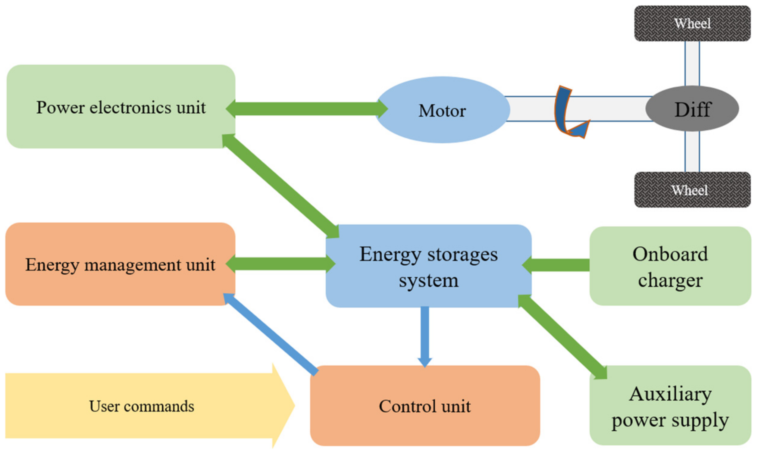
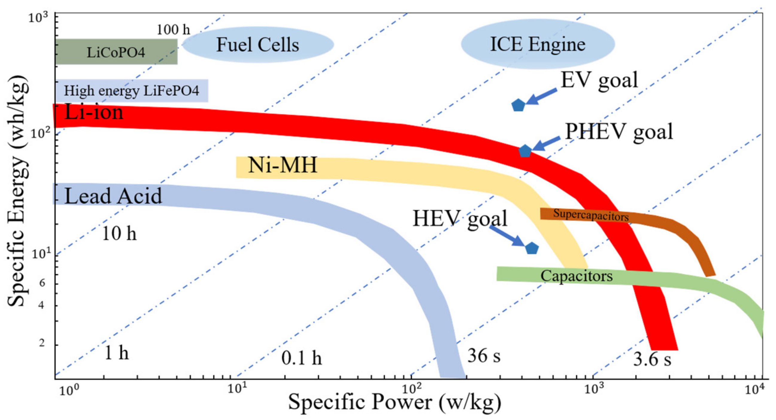
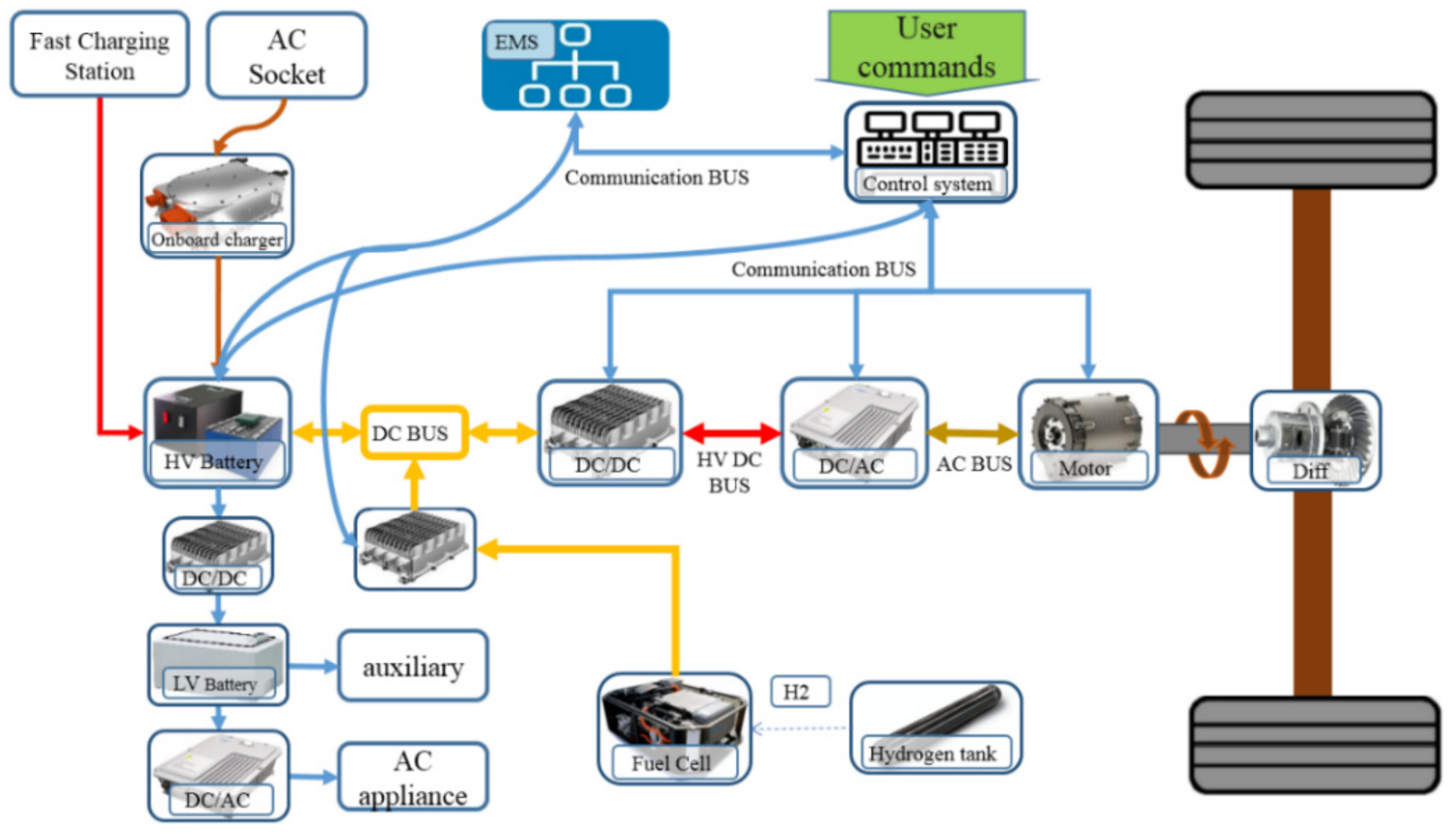
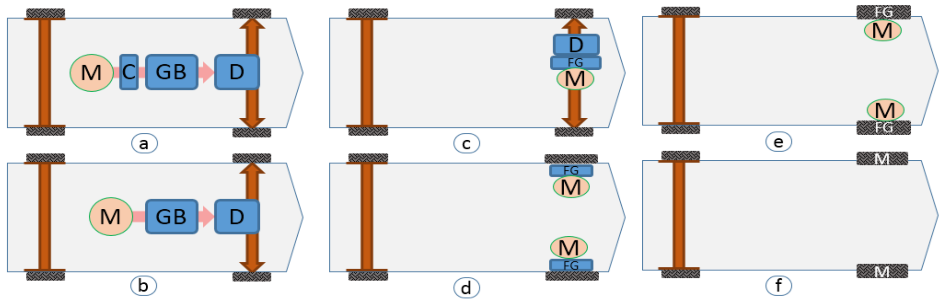
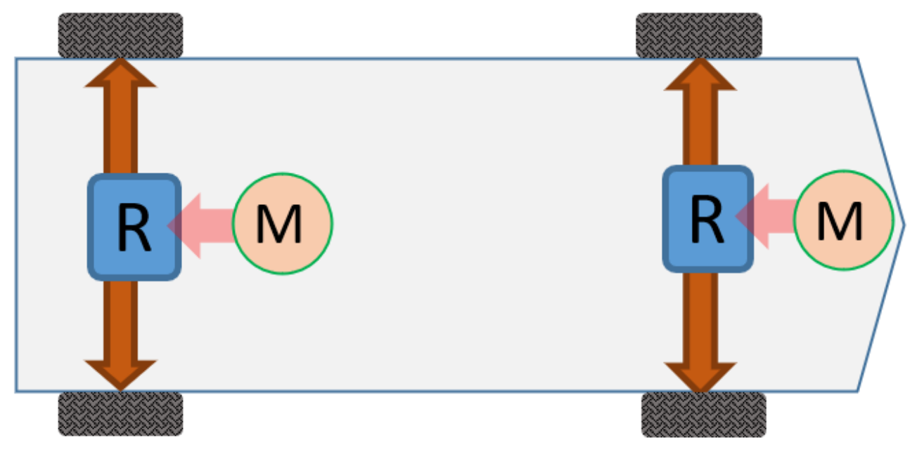
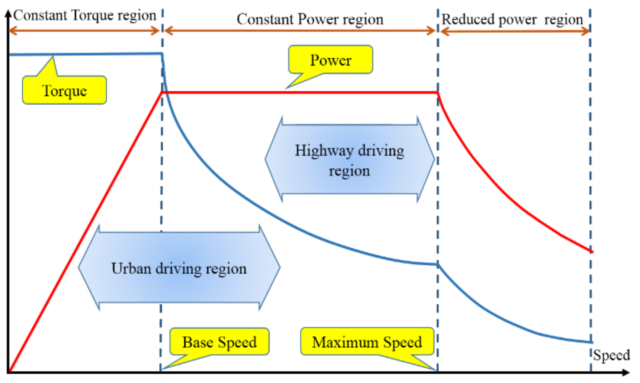
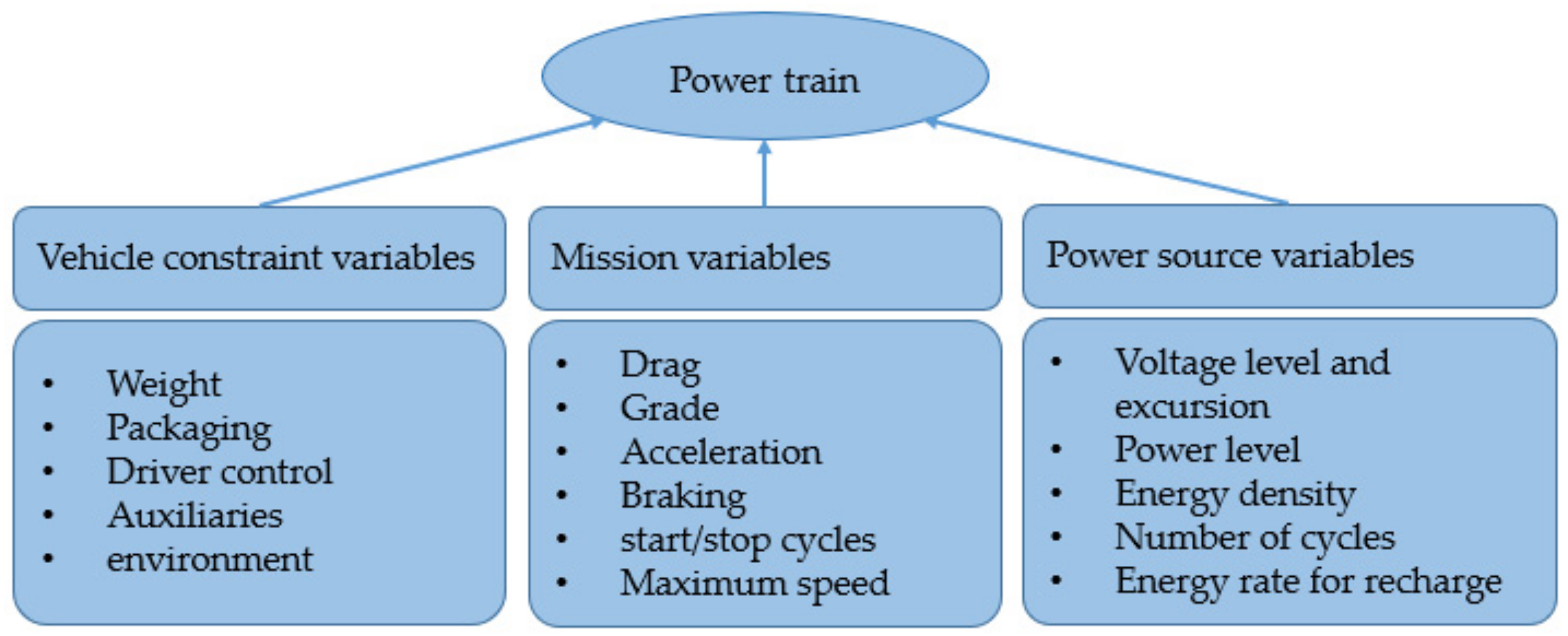
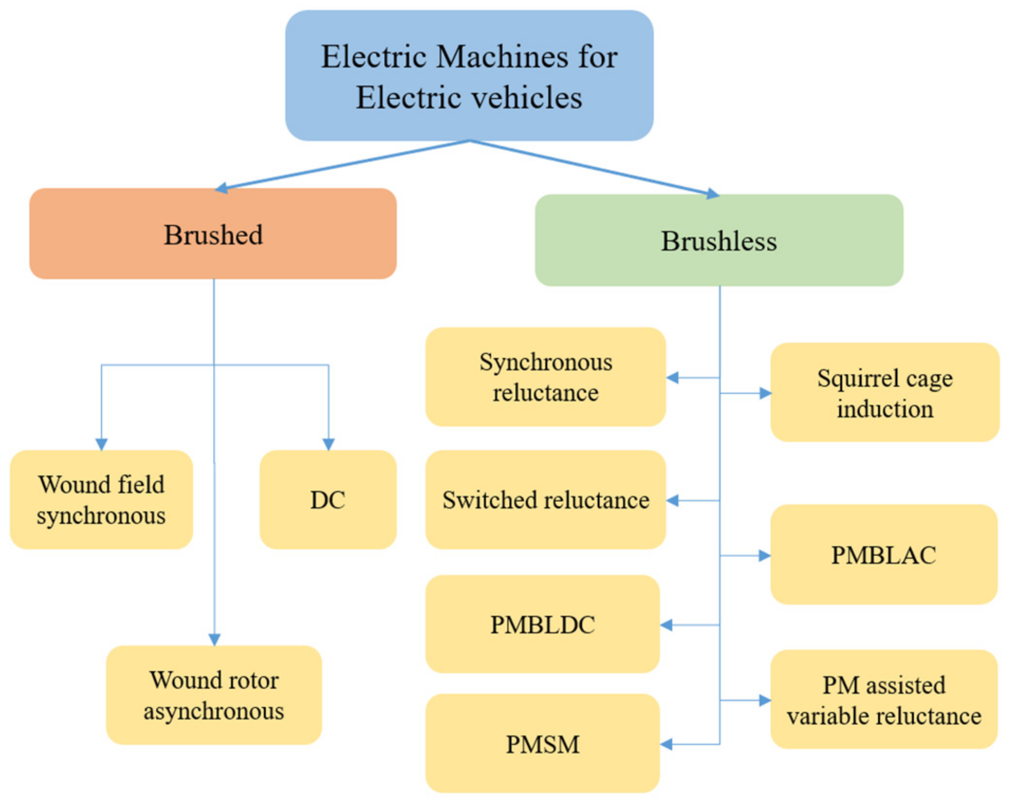
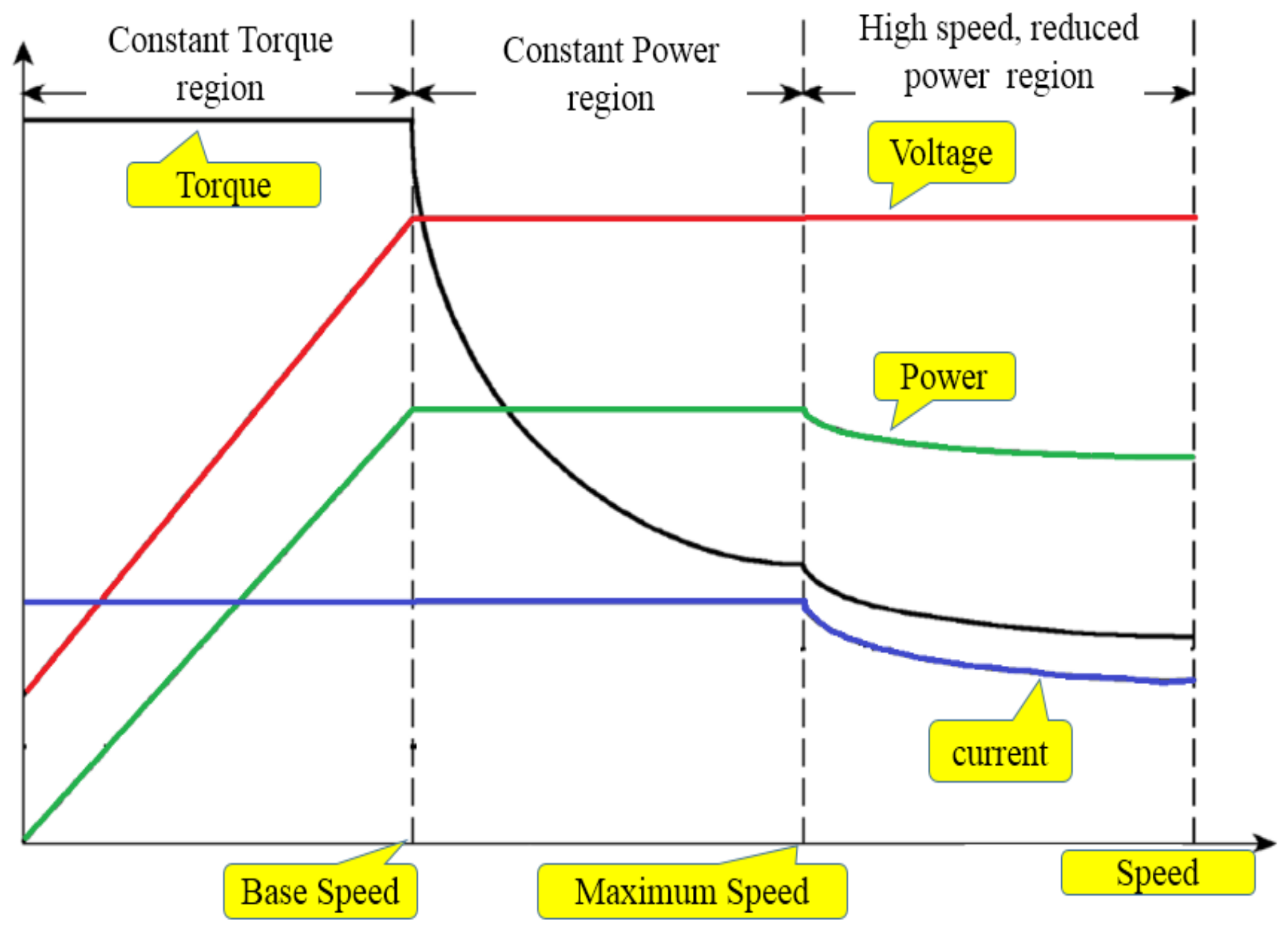
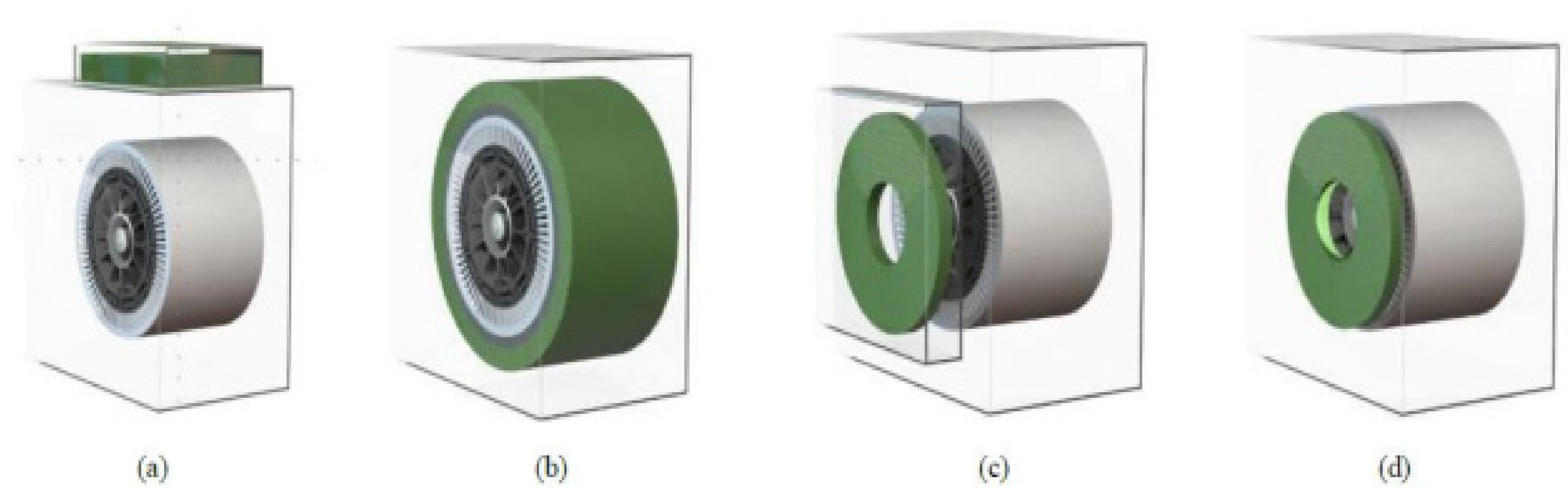
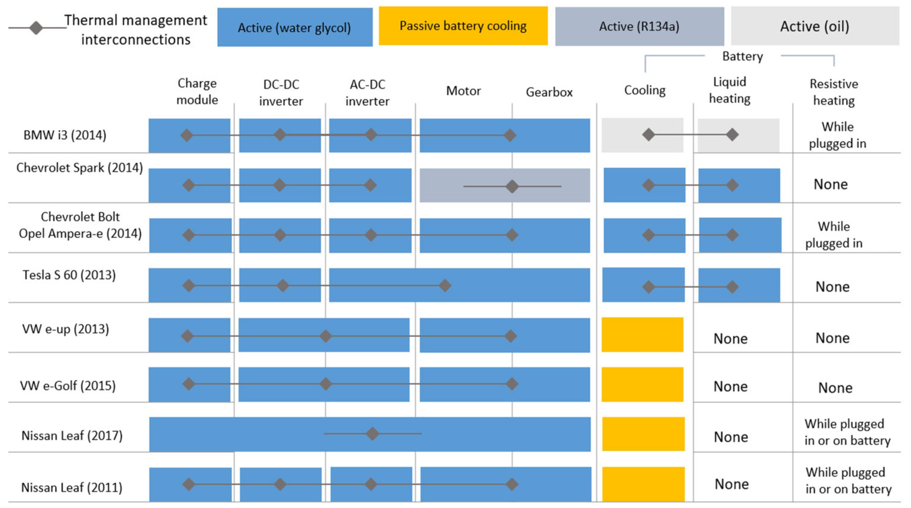
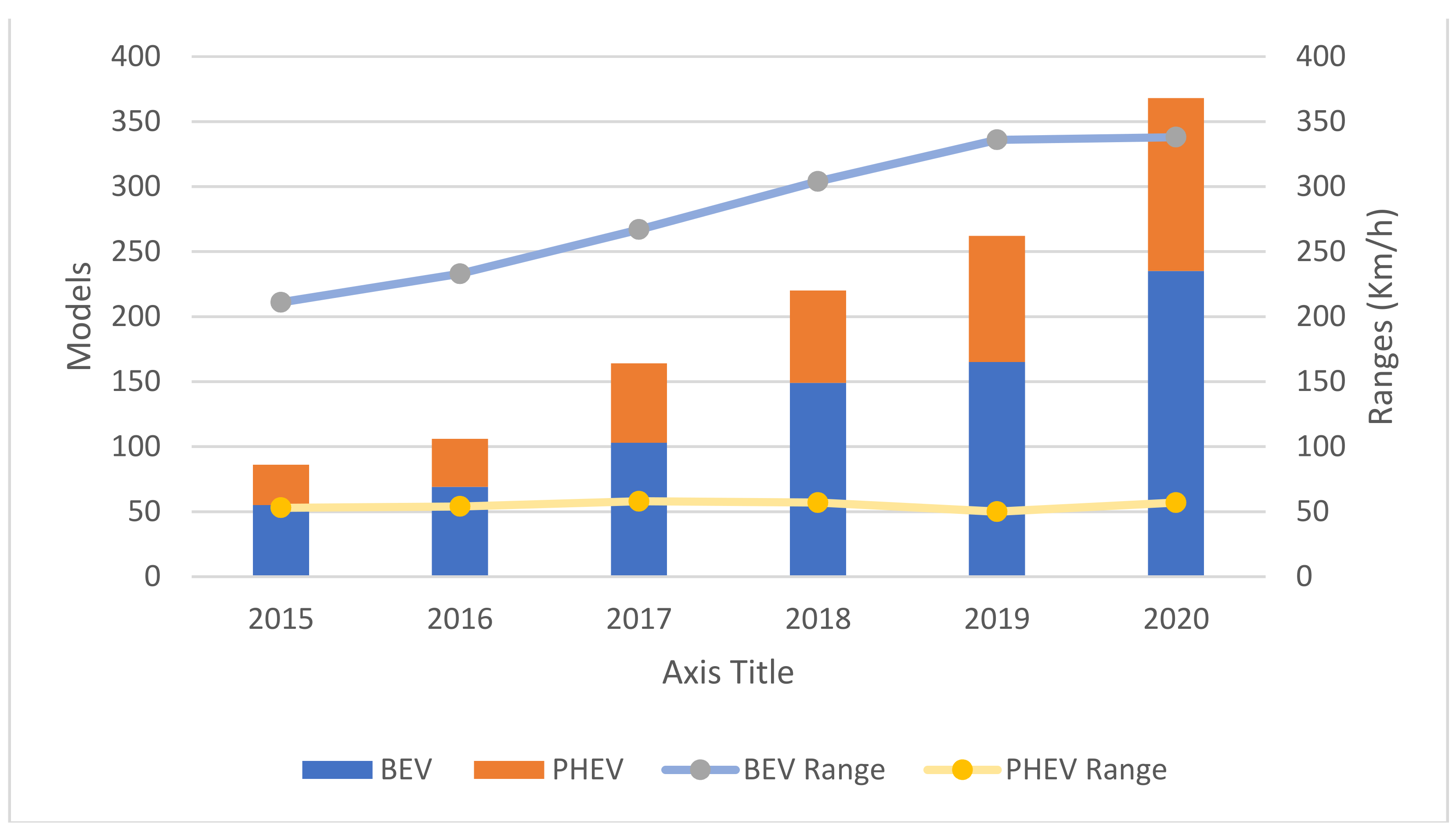
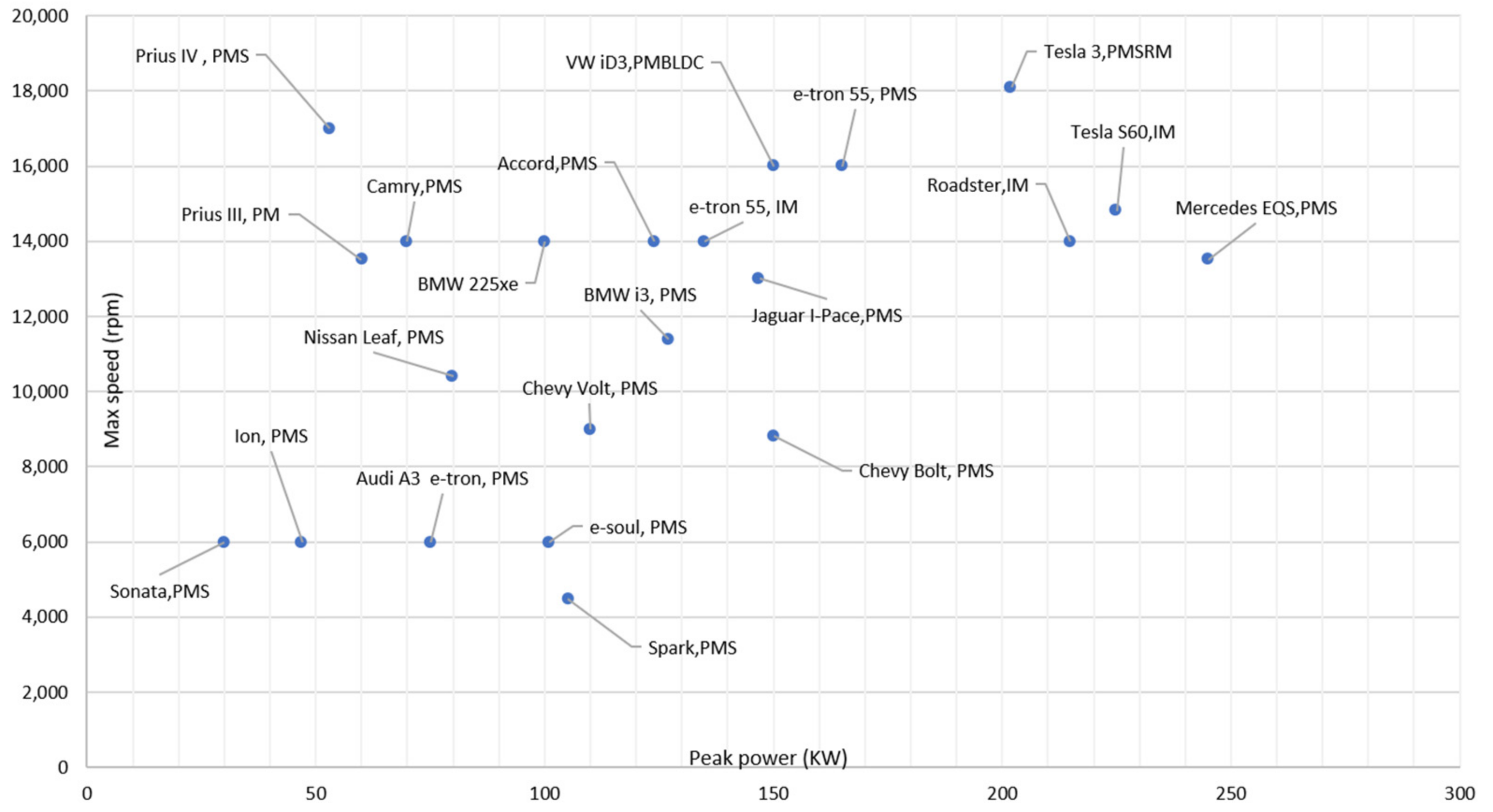
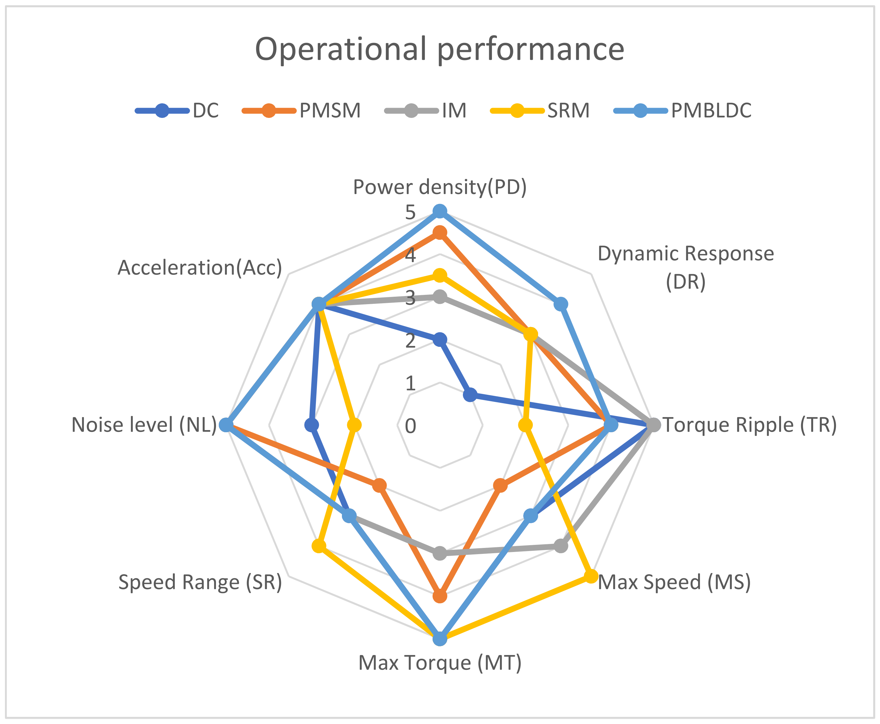
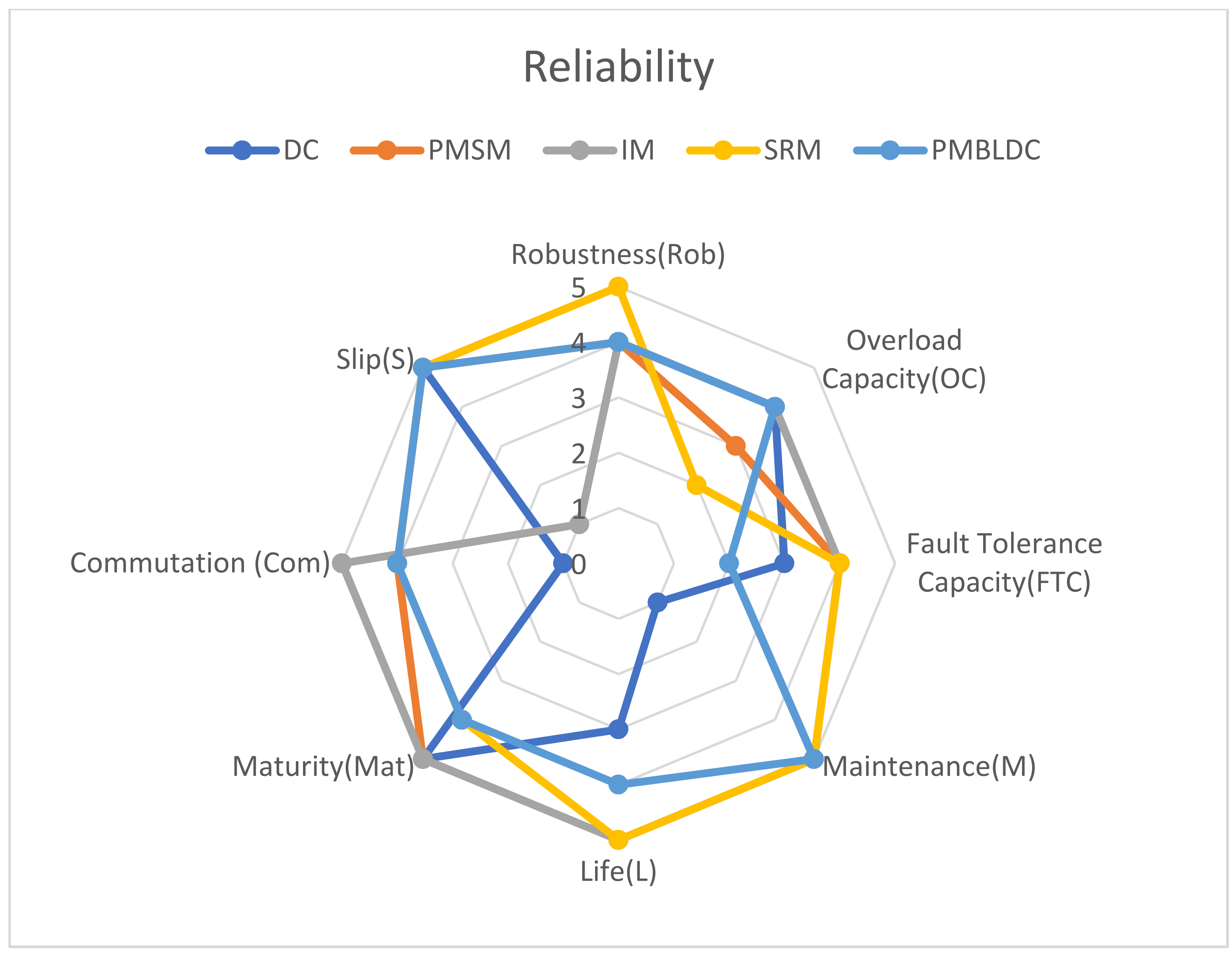
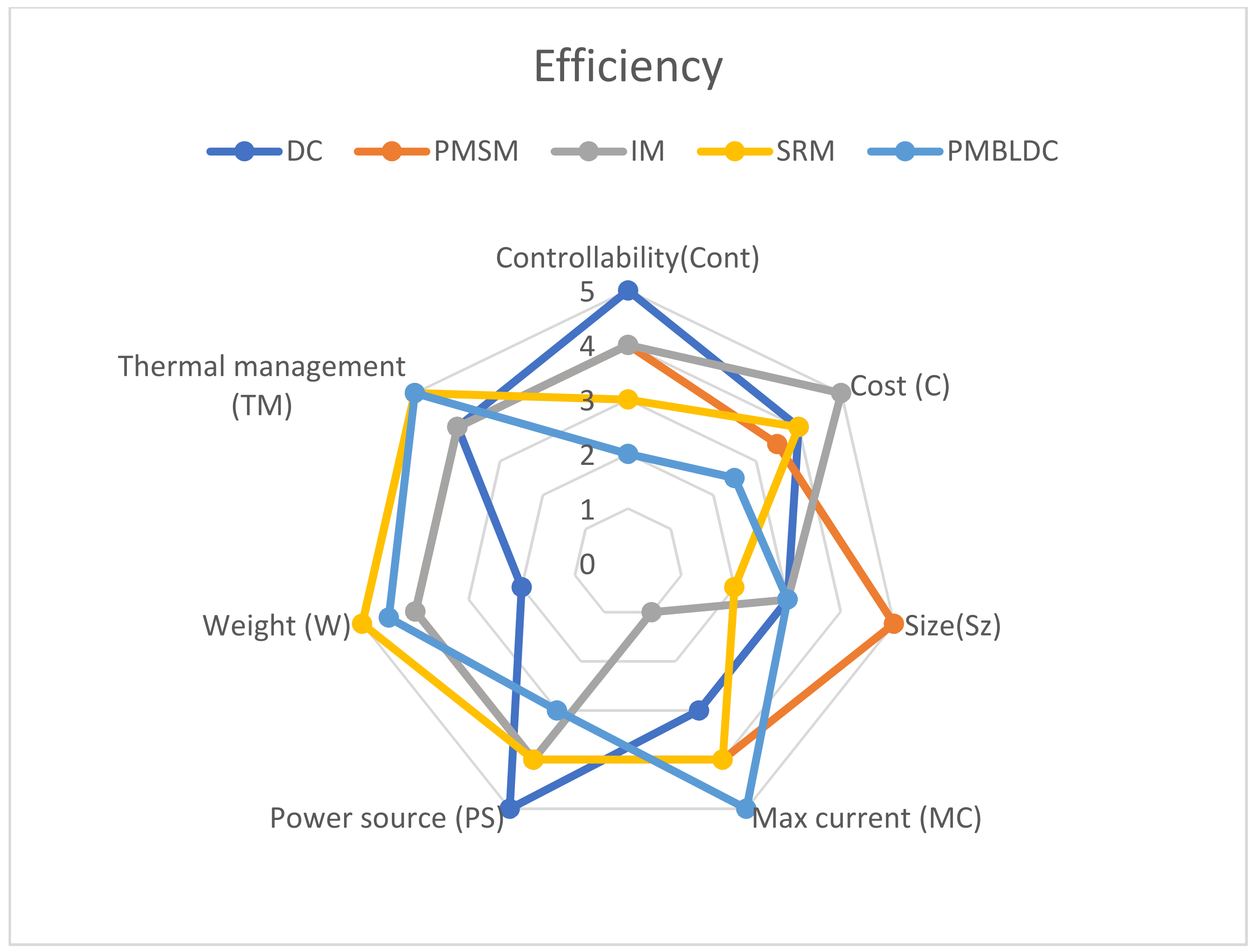
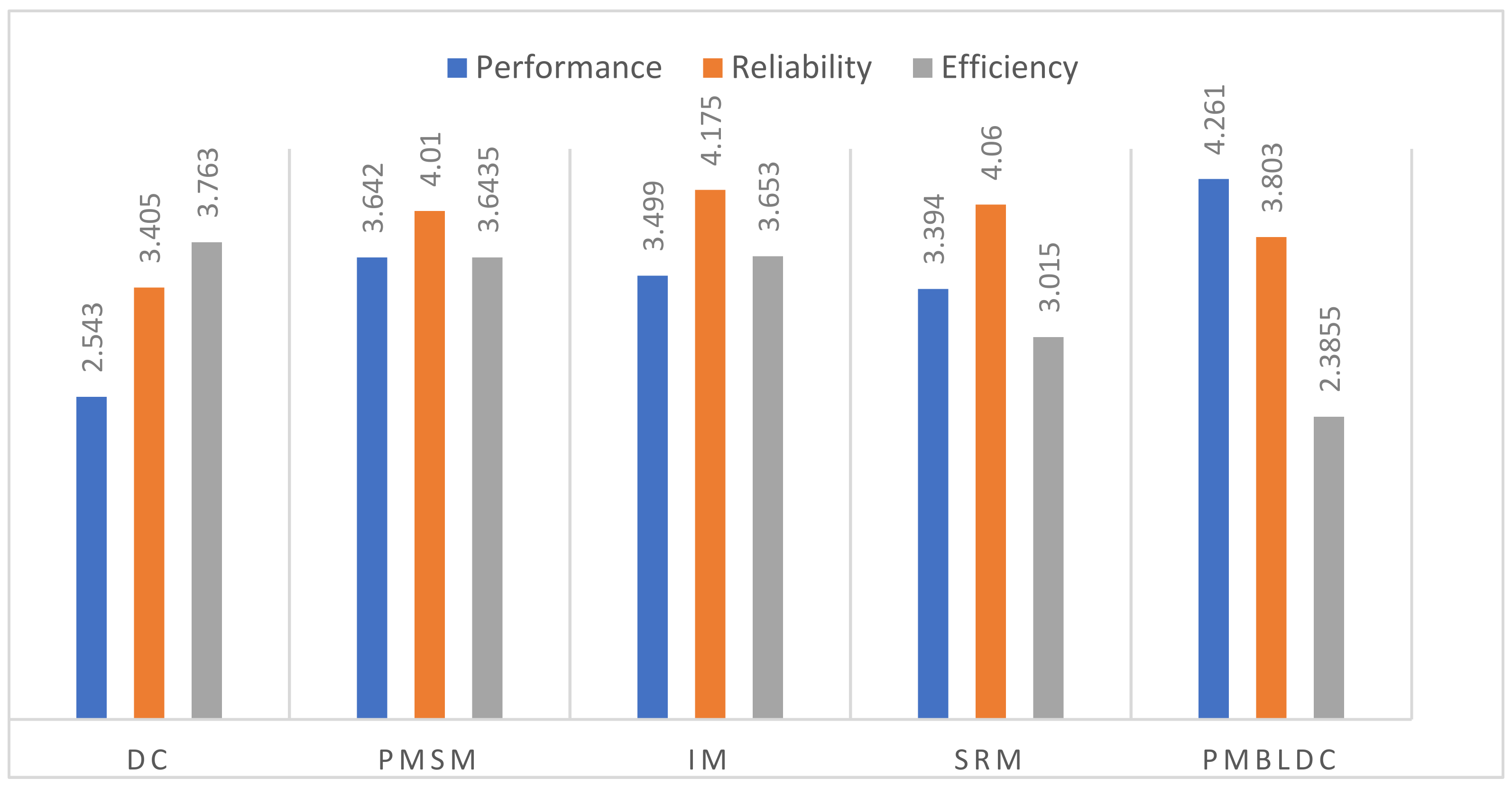
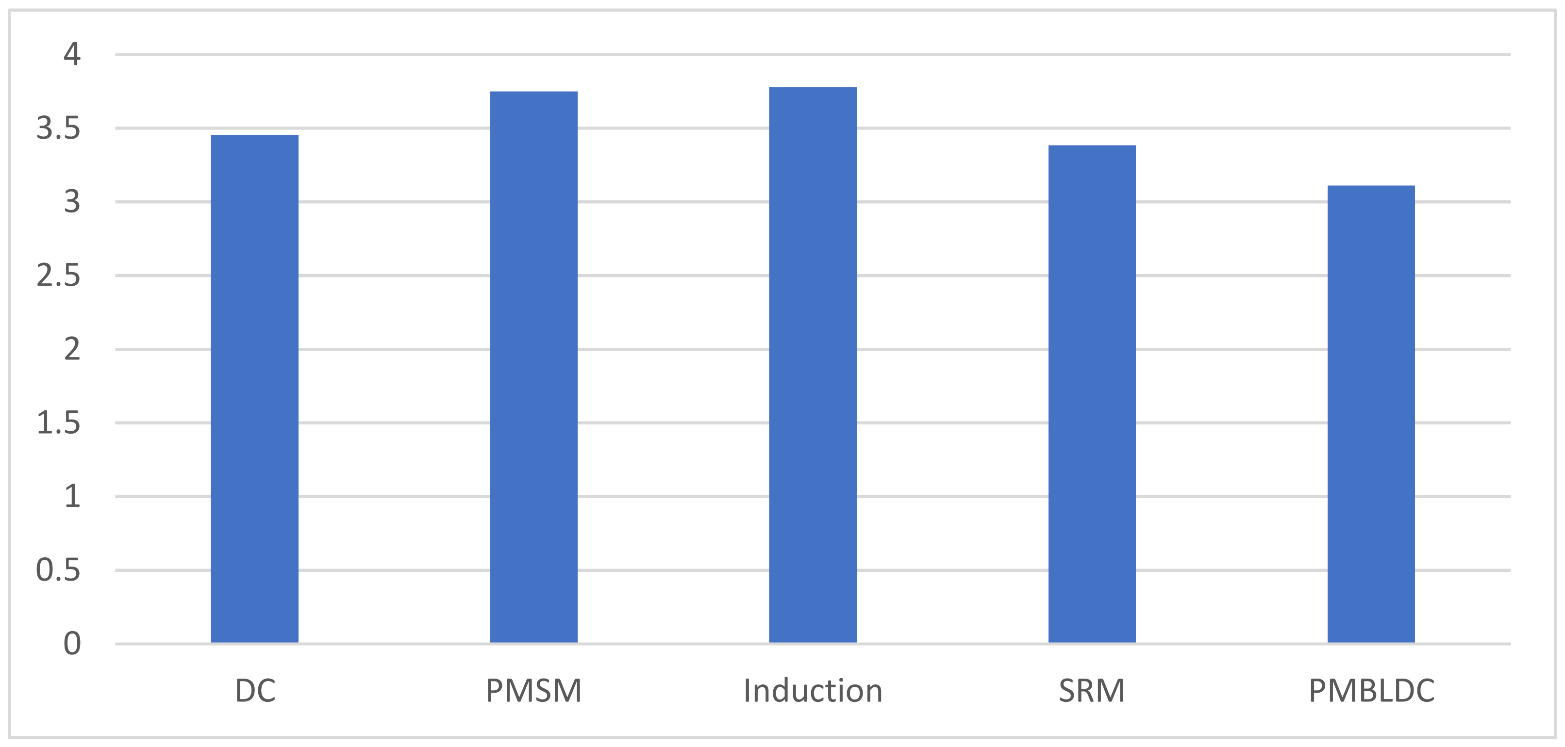