Article

Virtual Flux Voltage-Oriented Vector Control Method of Wide Frequency Active Rectifiers Based on Dual Low-Pass Filter

1
School of Electrical Engineering, Tiangong University, Tianjin 300387, China
2
WEICHAI Power Co., Ltd., Weifang 261061, China
*
Author to whom correspondence should be addressed.
World Electr. Veh. J. 2022, 13(2), 35; https://doi.org/10.3390/wevj13020035
Submission received: 31 December 2021 / Revised: 21 January 2022 / Accepted: 4 February 2022 / Published: 7 February 2022
(This article belongs to the Special Issue Power Converters and Electric Motor Drives)

Abstract

:
This article presents a non-AC-side voltage sensor control method applied to More Electric Aircraft rectifiers. The control strategy can operate properly over a wide range of frequencies. This strategy calculates the AC supply frequency through an instantaneous phase-locked loop and feeds it back to a dual low-pass filter. The reconstructed rectifier-side voltage is filtered using two low-pass filters with different scale factors. Then, the values of the two filter outputs are subtracted and the effect of the DC bias due to the initial value of the integration is eliminated. The subtracted value is amplitude-phase compensated to calculate the virtual flux value. The phase angle can then be calculated from the virtual flux value. This phase angle is used for the implementation of the voltage-oriented vector control and as an input to the instantaneous phase-locked loop. Simulation and experimental results show that the use of dual low-pass filters under different frequency conditions improves the speed and accuracy of virtual flux estimation and eliminates DC-side bias errors.

1. Introduction

Some commercial transport aircraft use main generators connected directly to the jet engines via gearboxes to generate electricity. Compared with a constant frequency AC power supply, it has the following characteristics: firstly, the application of a variable frequency AC starter improves the disadvantage that constant speed and constant frequency AC power cannot start an aero-engine; secondly, the efficiency of the power generation system is increased from 70% to 90% of the constant speed and constant frequency AC power supply, which creates the conditions for increasing the power capacity. In addition, the frequency-converted AC power supply has a simple structure, small size, and low failure rate [1]. Traditional aircraft use a transformer rectifier or auto-transformer rectifier unit to provide DC voltage, which increases the weight and volume of the aircraft [2,3]. Use of a PWM rectifier can reduce weight and volume and improve power factors, such as the two-level PWM rectifier [4] and Vienna rectifier [5,6], and has a power factor correction function [7]. The PWM rectifier has a simple structure and low total harmonic distortion of input current [8], but its overall system cost is high. Reducing the cost of PWM rectifiers has become one of the current research hotspots [9,10,11,12].
Voltage sensors and current sensors are required to control three-phase PWM rectifiers. In a three-phase PWM rectifier system for an More Electric Aircraft, rapid changes in frequency can lead to a rise in temperature, which in turn leads to a reduction in sensor accuracy. Therefore, More Electric Aircraft use of PWM rectifier control schemes without AC-side voltage sensors is the future trend. Reducing the use of sensors reduces overall cost, enhances robustness to high-frequency noise, eliminates sensor measurement offset errors, reduces the weight of the system and slightly improves conversion efficiency by eliminating sensor losses [13]. For this reason, scholars have proposed several AC-side voltage-sensorless schemes.
The voltage across the inductor is proportional to the rate of change of the current flowing through the inductor. Therefore S. Hansen et al. proposed a sensorless control method that uses the differential of the current for voltage estimation [14]. Differential calculations in experiments may produce problems such as high-frequency noise, resulting in inaccuracies in the calculated voltage values. Liang proposed a predictive control of the sliding-mode virtual flux observer-based model without AC-side voltage sensors. This control method has excellent filtering capability and does not suffer from high-frequency dithering. This control method solves the problem of DC bias errors to improve the dynamic response [15]. However, the method requires a large number of calculations to obtain a complete system model, and its performance depends on the accuracy of the parameters in the model.
A new sensorless control scheme for the three-phase pulse-width-modulated rectifier is proposed. This scheme uses an adaptive neural estimator, which is essentially an integration of time. When using the virtual flux approach for AC voltage sensorless control, the essence is the integration of the rectifier voltage. Because of the problems of DC drift and saturation when performing integration, integrators are often replaced by a low-pass or band-pass filters [16]. To reduce the influence of the integrator, [17] uses two low-pass filters cascades and [18] uses three low-pass filter cascades to replace the pure integrator, and the amplitude-phase compensates. Reliable operation can occur without an AC side voltage sensor, but with large transient components. For this reason, [19] proposes a virtual flux observer with a negative feedback resonant filter and proposes a delay compensation algorithm to solve the DC offset caused by the voltage vector integral in the calculation of the virtual flux vector to solve the problem of virtual flux delay. The above scheme can only set a fixed cutoff frequency, and the operating frequency range is narrow. The researchers in [20] proposes a frequency-adaptive virtual flux linkage estimation method which configures a second-order generalized integrator as a quadrature signal generator. This method can operate under the condition of frequency variation or grid imbalance, but its structure is complex, and using the parameters of the PI controller will affect the accuracy. A novel integration algorithm has been proposed in [21]. The algorithm uses a virtual magnetic chain direct power control method. The method also verifies the performance in the case of grid frequency fluctuations. However, the fluctuation of the grid frequency with a maximum value of 3 Hz does not prove the feasibility in More Electric Aircraft.
In order to solve the problem of the DC bias and amplitude-phase errors of virtual flux linkage under broadband conditions, a virtual flux voltage-oriented vector control strategy based on dual low-pass filters is proposed in this article. The control strategy uses a dual low-pass filter with amplitude and phase compensation. It subtracts the two output values, thereby eliminating the effects of DC offset errors. Then, through the amplitude-phase compensation module, the virtual flux linkage is finally obtained by calculation. The control strategy uses instantaneous phase-locked loop acquisition to quickly and accurately detect the power supply frequency. The frequency value is fed back into the dual low-pass filter, ensuring that the dual low-pass filter can operate consistently over a wide frequency range. The control strategy can be used in the normal operation of More Electric Aircraft power supply frequency changes and has a great advantage over the traditional virtual flux directional vector control strategy.
To verify the feasibility of this control scheme in a More Electric Aircraft wide frequency environment, the feasibility of the scheme is verified in this article under the condition that the power supply frequencies are 50 Hz, 100 Hz, and 200 Hz respectively, and simulates the operation state of More Electric Aircraft at different frequencies. The entire control system is divided into five main modules: a rectifier power circuit module, an instantaneous phase-locked loop module, a dual low-pass filter module, an angle estimation module, and a PI control module.
A virtual flux voltage-oriented vector control method of wide frequency active rectifiers based on the dual low-pass filter is designed in this paper for More Electric Aircraft. Section 2 describes in detail the modelling of the three-phase PWM rectifier and the mathematical model of the rectifier constructed using a virtual flux. Section 3 studies the specific principle of the dual low-pass filter to calculate virtual flux linkage and the design of the instantaneous phase-locked loop, and also explains in detail the control principle of the dual low-pass filter. In Section 4, the above theoretical analysis is experimentally verified. Section 5 outlines our conclusions.

2. PWM Rectifier Model Based on Virtual Flux

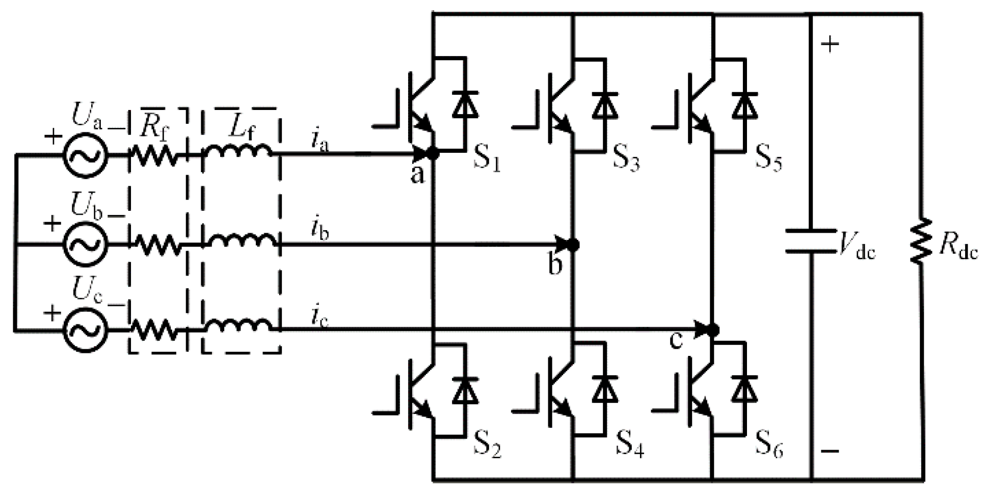
2.1. Mathematical Model of Three-Phase PWM Rectifier

Figure 1 shows the main circuit of the three-phase voltage PWM rectifier. In Figure 1, Va, Vb, Vc are the three-phase AC phase voltages, ia, ib, ic are the three-phase AC currents, S1-S6 are the six switch signals, Vdc is the rectifier DC side voltage, Lf is the filter inductor, Rf is the sum of the resistance of the filter inductor and the equivalent resistance of the switching losses, and RL is the load resistance.
The following differential equation represents the mathematical model of the rectifier:
{ V Ra = V a R f i a L f d i a d t V Rb = V b R f i b L f d i b d t V Rc = V c R f i c L f d i c d t
where VRa, VRb, VRc indicate the voltage on the side of the PWM rectifier. The parameters in the above equation are transformed into an αβ two-phase static coordinate system by orthogonal mapping, assuming that the line impedance is 0. The mathematical model of the rectifier in the static coordinate system is collated as follows:
{ V R α = V α L f d i α d t V R β = V β L f d i β d t
where V and V are the projection of the rectifier-side voltage vector in a two-phase static coordinate system, which can be represented by the DC-side voltage and the switching function. The equation is:
{ V R α = 2 3 V d c ( S a 2 ( S b + S c ) ) V R β = 3 3 V d c ( S b S c )
where Sa, Sb, and Sc are the switching functions of the three-phase rectifier, respectively. Taking the A phase as an example, Sa = 1 indicates that the upper bridge arm is on and the lower converter arm is off. Likewise, Sa = 0 indicates that the lower bridge arm is on and the upper converter arm is off. The other two-phase bridge arm switching functions are identical.

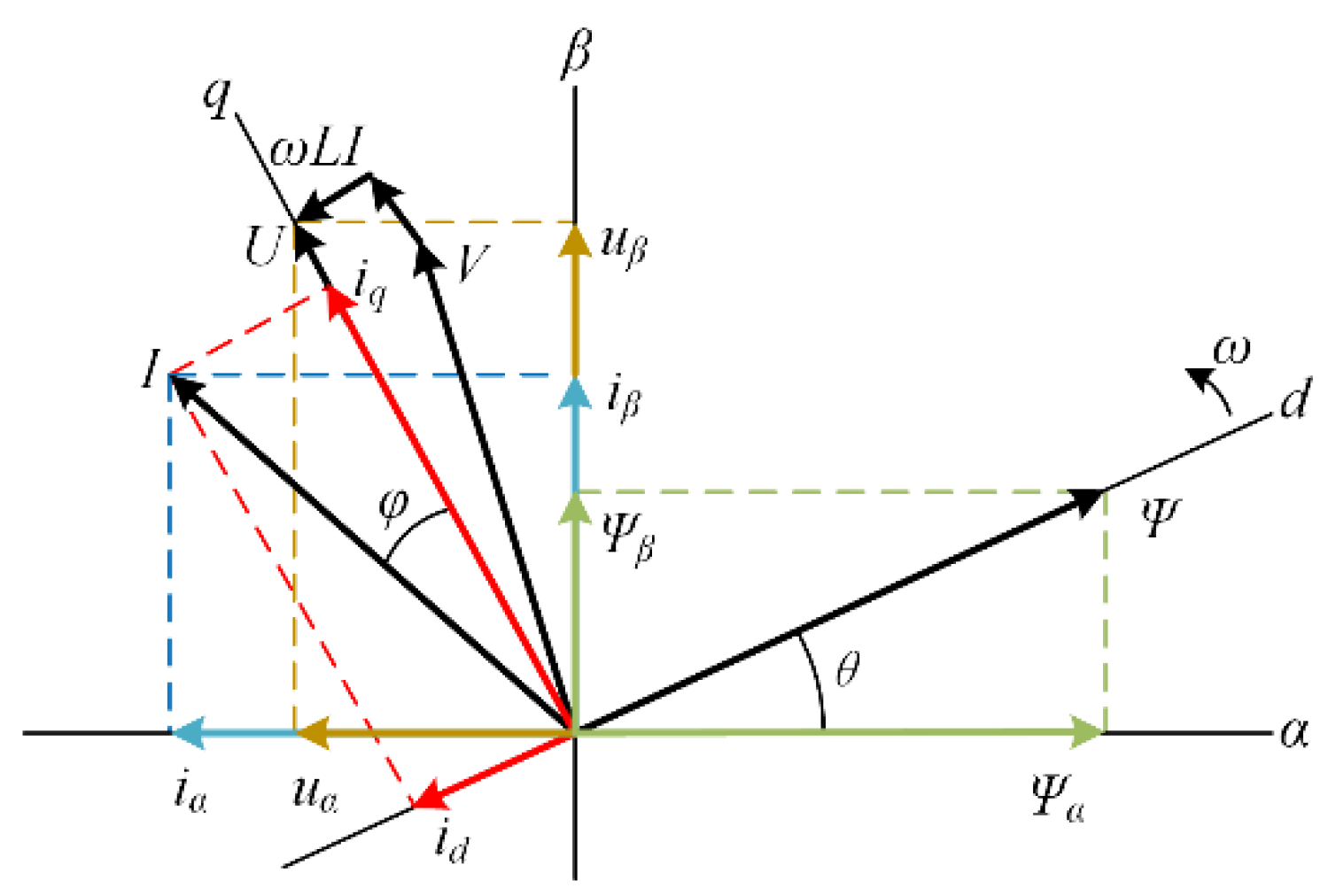
2.2. Model of Mathematics Based on Virtual Flux

Due to the reversibility of the rectifier and the inverter, the grid voltage in the PWM rectifier is equivalent to the induced EMF generated in the stator winding by the air gap magnetic field of the AC motor. The filter inductance and resistance are equivalent to the phase inductance and resistance of the motor stator winding. The PWM rectifier is equivalent to a synchronous motor running at a constant, synchronous speed.
In general, the flux of a permanent magnet synchronous motor can be observed directly in the stator coordinate system. Subtract this flux from the given value. The difference is controlled by a hysteresis loop controller which, according to the current flux state, selects the corresponding voltage space vector for direct torque control of the motor [22]. In the PWM rectifier, the grid voltage is equivalent to the differential of a virtual flux. This method, similar to the observation of the flux of permanent magnet synchronous motors, is used to observe the virtual flux instead of the grid voltage as an orientated vector. This approach reduces the use of three-phase AC line voltage sensors and ensures the reliability of the system.
The procedure is as follows, first integrating both sides of Equation (2), the result obtained is:
{ V R α d t = ( V α L f d i α d t ) d t V R β d t = ( V β L f d i β d t ) d t
Let V α d t = ψ α and V β d t = ψ β , where ψα and ψβ are components of virtual power grid flux in the two-phase static coordinate system. Substituting the virtual flux component of the α-axis β-axis into Equation (4) gives:
{ V R α d t = ψ α L f i α V R β d t = ψ β L f i β
Thus, the virtual flux can be expressed using the rectifier side voltage and the product of the inductance and the current. Since the integration of the grid voltage in the static coordinate system is the virtual flux, the grid voltage vector is ahead of the virtual flux vector by an electric angle of 90°. The vector position relationship of the rectifier is shown in Figure 2.
In the virtual flux observer, the virtual flux circle obtained will deviate from the actual flux center because the difference in the initial value of the integration chosen directly uses a different initial value of integration, resulting in a DC bias error. To avoid this situation, scholars have used low-pass filters instead of pure integrators to obtain the effect of eliminating the DC bias at a steady-state [23].

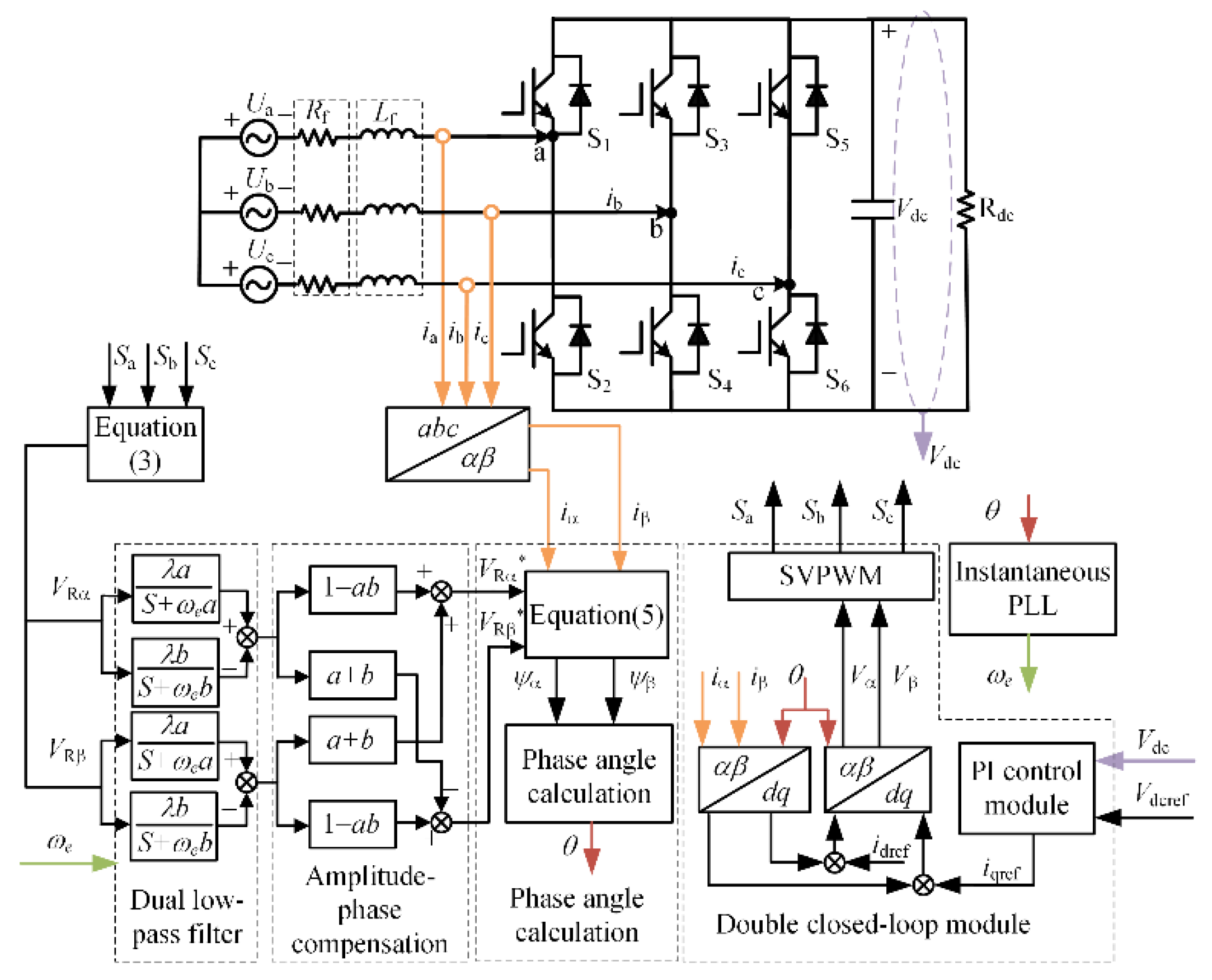
3. Wide Frequency Active Rectifier Control Strategy

3.1. Problems with Traditional Virtual Flux Observers

The specific block diagram for estimating the virtual flux using the low-pass filter method is shown in Figure 3. Although this method is smaller than the integral method DC bias error, this method does not eliminate the effect of the DC bias error, which uses a low-pass filter, resulting in a magnitude offset and a phase shift.
The traditional virtual flux observer is analyzed as follows, assuming the following expression for the voltage on the rectifier side:
x ( t ) = A sin ( ω e t + φ ) + B
where ωe is the three-phase power supply angular frequency, B is the amount of DC bias error, ϕ is the initial phase angle of the signal and A is the sinusoidal signal maximum.
The discrete model expression for a first-order low-pass filter is given by:
y ( k ) = λ 1 x ( k ) + λ 2 y ( k 1 ) = n = 0 k 1 λ 1 λ 2 n x ( n ) + λ 2 k y ( 0 )
where the expressions for λ1 and λ2 are as follows:
{ λ 1 = T s 1 + ω c T s λ 2 = 1 1 + ω c T s
When k tends to infinity, the system will reach a steady state, and the DC error part of the Equation (7) tends to zero. Substituting Equation (6) into Equation (7) and simplifying it, we obtain:
y ( k ) = n = 0 k 1 λ 1 λ 2 n A sin ( ω e n + φ ) + B ω c
As can be seen from Equation (9), the low-pass filter reduces the effect produced by the initial value of the integration, but there is still a DC error B/ωc. The smaller the cut-off frequency ωc, the smaller the amplitude and phase error of the observed virtual flux. However, the filter becomes worse at suppressing DC bias errors. The low-pass filter does not fully eliminate the effect of DC errors for virtual flux observations, and the disadvantages of the integrator are not fully solved.

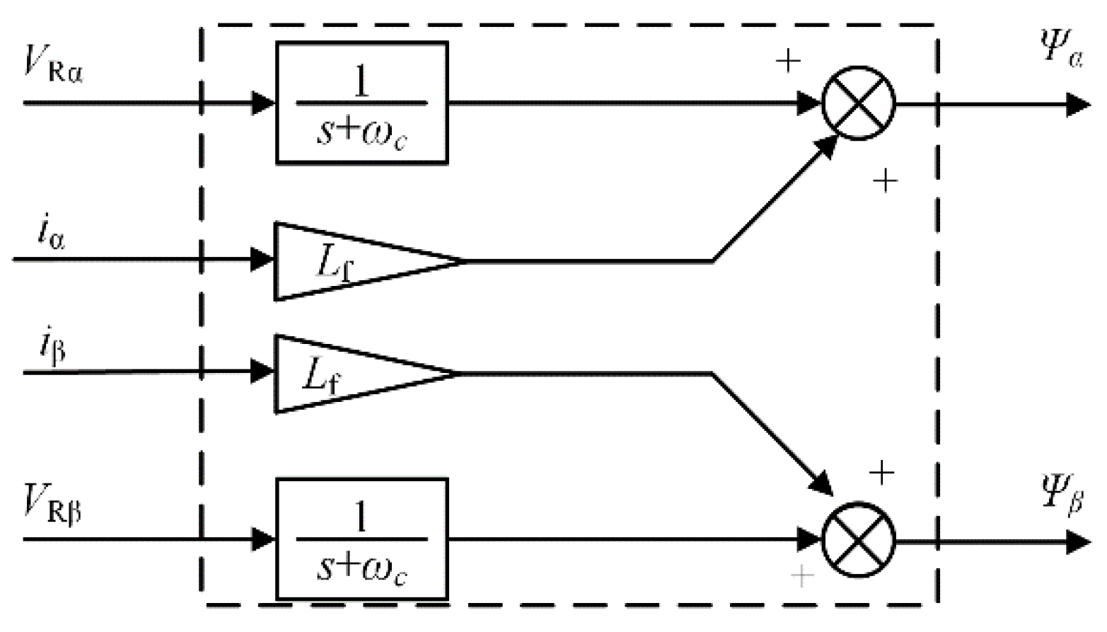
3.2. Dual Low-Pass Filter Design

This article uses a dual low-pass filter approach, the basic principle of which is to use two low-pass filters with different cut-off frequencies and scale factors. The input signal is filtered, and the output signal is subtracted. Using this method solves the problem of the initial value of the integration at the zero moments, which will lead to a DC bias error.
The dual low-pass filter expression is as follows:
Y ( s ) = ( λ a s + a ω e λ b s + b ω e ) X ( s )
The discretization expression is as follows:
y ( k ) = n = 0 k 1 λ a T s 1 + a ω e T s ( 1 1 + a ω e T s ) n x ( n ) n = 0 k 1 λ b T s 1 + b ω e T s ( 1 1 + b ω e T s ) n x ( n ) + ( 1 1 + a ω e T s ) k y ( 0 ) ( 1 1 + b ω e T s ) k y ( 0 )
This article makes λaλb = 1, When a and b are determined λ is naturally also a constant value. From Equation (11), it can be seen that in the steady-state of the system, k tends to infinity and the coefficients of y(0) all tend to 0. Therefore the effect of the initial value can be eliminated. Substituting λaλb = 1 and Equation (6) into Equation (11), and can be obtained as:
y ( k ) = n = 0 k 1 λ a T s 1 + a ω e T s ( 1 1 + a ω e T s ) n A sin ( ω e n + φ ) n = 0 k 1 λ b T s 1 + b ω e T s ( 1 1 + b ω e T s ) n A sin ( ω e n + φ )
The above equation shows that the dual low-pass filter method eliminates the effect of the initial value of integration and solves the problem of DC bias in the virtual flux observation. However, the dual low-pass filter also has amplitude errors and phase shifts that need to be compensated-for. The frequency–domain expression for the virtual flux of the rectifier is as follows:
ψ = V R s + L f i = V R + L f i
where VR* is the integral value of the rectifier’s reconfigured voltage. The output of the rectifier-side voltage after the dual low-pass filter is as follows:
V Rd = ( λ a s + a ω e λ b s + b ω e ) V R
where VRd* is the integral value of the rectifier’s reconfigured voltage using a dual low-pass filter. Combining Equations (13) and (14) gives the following compensation equation:
V R V Rd = 1 s / ( λ a s + a ω e λ b s + b ω e ) = 1 a b j ( a + b )
The rectifier-side voltage vector decomposes into a two-phase static coordinate system. The virtual flux vector rotates first through the α-axis and then through the β-axis so that VRα is always ahead of VRβ in the time coordinate system by an angle of 90°. The mathematical relationship is as follows:
V R α = V R β e j π 2 = j V R β
After decomposing Equation (15) into a static coordinate system and substituting Equation (16) into it, the result after simplification is as follows:
{ V R α = ( 1 a b ) V Rd α + ( a + b ) V Rd β V R β = ( 1 a b ) V Rd β ( a + b ) V Rd α
The resulting model of the dual low-pass filter with added compensation is shown in the dashed box in Figure 4. The model of the dual low-pass filter consists of two parts: one is the dual low-pass filter module and the other is the compensation module.

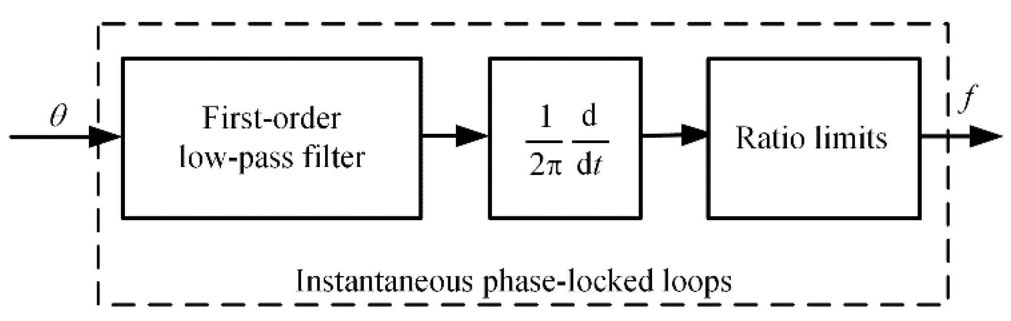
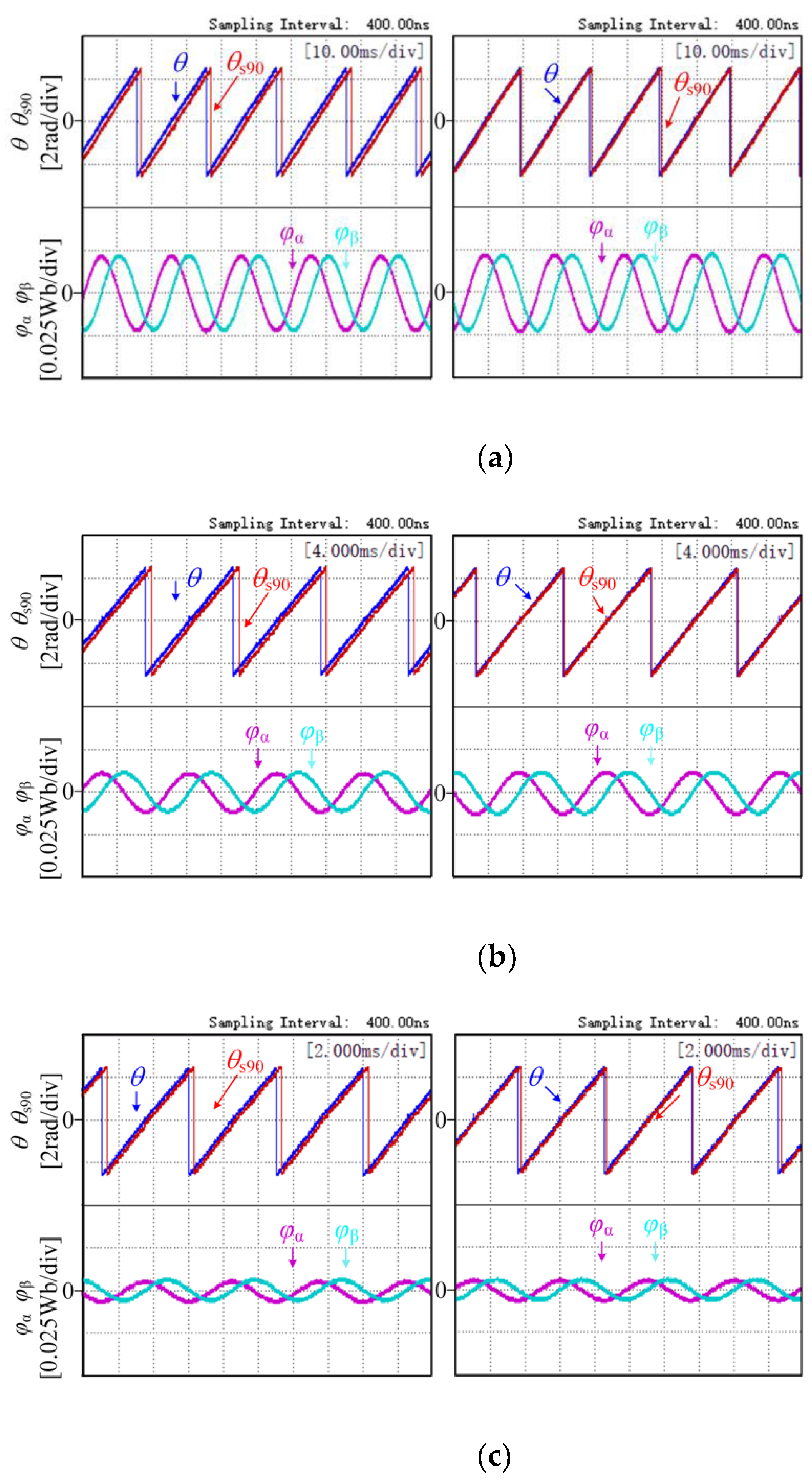
3.3. Phase Angle Calculation and Instantaneous Phase-Locked Loop Design

By substituting Equation (17) into Equation (5), the value of the virtual flux in the static coordinate system can be calculated as follows:
{ ψ α = V R α + L f i α ψ β = V R β + L f i β
The phase angle of the virtual flux vector can be calculated from the virtual flux values in the static coordinate system as follows:
{ sin θ = ψ β ψ α 2 + ψ β 2 cos θ = ψ α ψ α 2 + ψ β 2
This equation converts the components of the virtual flux in a static coordinate system into phase angles. These phase angles are used as inputs to the instantaneous phase-locked loop.
Like the variable frequency of a More Electric Aircraft, the parameters of the dual low-pass filter need to be corrected over time. The controller needs to sample the angular frequency of the AC side of the power supply over time. Typically, controllers use a phase-locked loop to detect the frequency. The phase-locked loop consists of a phase detector, a PID controller with an automatic gain control, a controlled oscillator, and a low-pass filter. Since the tuning of the PID controller is simplified, the frequency variation range is small. This paper uses an instantaneous phase-locked loop, using the phase angle calculated by the virtual flux as the input to the instantaneous phase-locked loop, as shown in Figure 4.
The first-order low-pass filter is used to reduce the high-frequency noise generated during the phase-to-position angle calculation. The ratio limiter suppresses frequency spikes due to discontinuities in the phase angle signal. Based on the output frequency value of the instantaneous phase-locked loop, the controller performs calculations to obtain the power supply angular frequency. Then, the controller passes the source angular frequency to the dual low-pass filter module. This approach implements the solution proposed in this article.

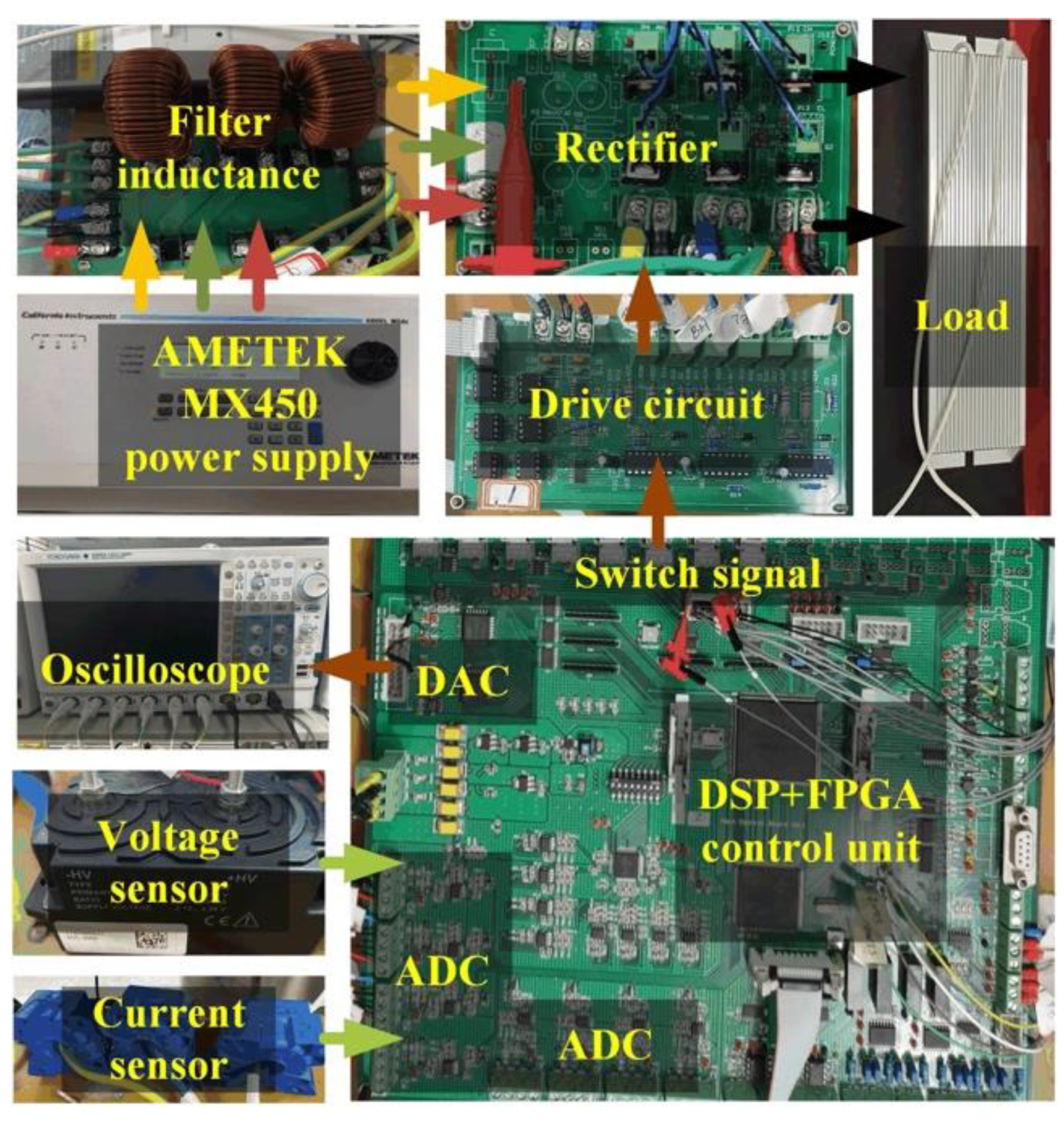
4. Experimental Results and Analysis

The control system block diagram is shown in Figure 5. To verify the feasibility of the control strategy proposed in this paper, an experimental system was set up, as shown in Figure 6.
Table 1 indicates the parameters of the control system. The experimental platform consists of a programmable inverter power supply, a rectifier, and drive and control circuits. The programmable variable frequency power supply provided a variable frequency three-phase AC output for the experiments. The digital signal processing chip of the control circuit was a DSP TMS320F28335 with an FPGA Cyclone chip; the rectifier used a MOSFET IRF4310, and the rectifier driver chip used an IR2110.

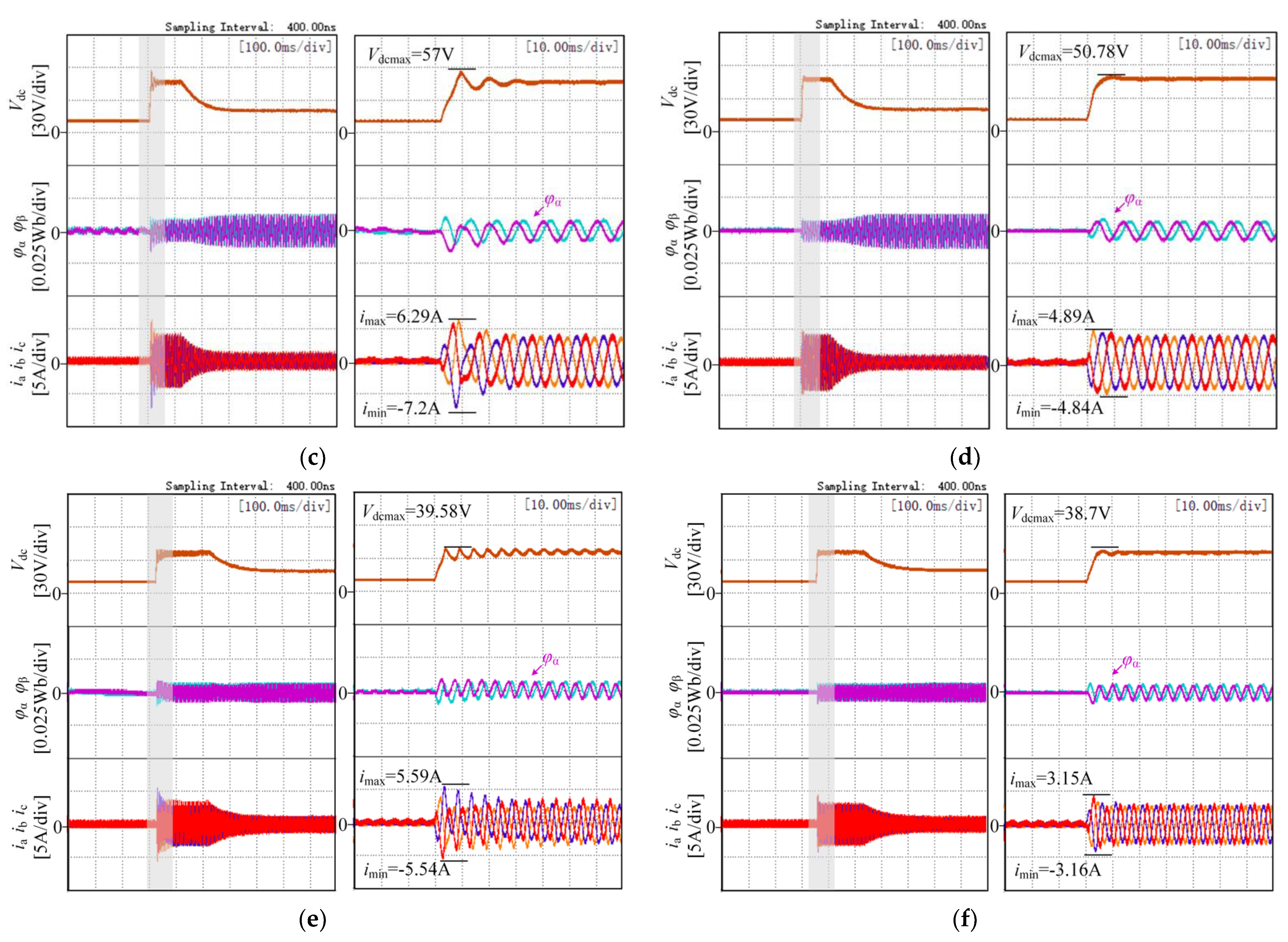
4.1. Start-Up Comparison Experiments

The virtual flux voltage-oriented vector control method uses an instantaneous phase-locked loop and a dual low-pass filter. This method is compared with a control scheme using only a first-order low-pass filter. The two control schemes compare the starting current and voltage, the virtual flux at start-up, the angular offset error at the steady state, and the reactive power at the steady state.
Figure 7 shows a thumbnail and enlarged view of the rectifier start-up waveforms at different frequencies. The shaded boxes show the enlarged plots. Since the PI regulation uses the same parameters, the time required from start-up to steady-state is approximately the same. The DC-side voltage at the start-up of the traditional method was compared with the proposed method. The comparison shows that the proposed solution has a smoother start-up of the DC-side voltage and a smaller overshoot of the voltage. Secondly, the virtual flux at the start-up of the traditional method was compared with the proposed method. The virtual flux of the proposed method returns to the sinusoidal state faster, indicating that the virtual flux was estimated faster than with the traditional method. The essential reason for this is that the traditional method does not have an integral initial value and takes some time to reach an accurate position.
Experiments were used to compare the three-phase starting currents of the traditional method and the proposed method. It is obvious from the graphs that the traditional method led to inaccurate estimation of the position angle due to the absence of the initial flux values, which ultimately led to severe distortion of the AC side current and excessive values of the starting current. The dual low-pass filter control scheme proposed in this paper had a faster start current recovery and reduced the peak start current by about 18%, 33%, and 44%, compared to the traditional method. As the frequency increased, the peak reduction in starting current gradually increased.

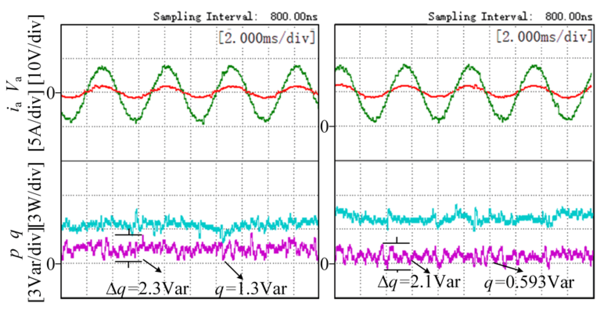
4.2. Comparison Experiments of Steady-State of the System

The effectiveness of the proposed scheme in compensating the phase angle of the virtual flux was experimentally verified. An experimental comparison was made between the calculated phase angles of the traditional method without compensation and the dual low-pass filter with added compensation, as shown in Figure 8. On the left is the traditional scheme waveform and on the right is the proposed scheme waveform. In the figure, θ is the actual virtual flux phase angle on the AC side, θs90 is the observed virtual flux phase angle, and ϕα and ϕβ are the components of the virtual flux in the static coordinate system. Figure 8 shows that the virtual flux phase angle estimation of the method proposed in this paper was more accurate for steady-state conditions at different frequencies because of the added phase compensation. The uncompensated method had a significant deviation in the virtual flux estimation scheme. In this paper, the cut-off frequency used in the traditional strategy takes a larger value, and it can be seen from Equation (9) that there is no DC bias problem when the cut-off frequency is overly large. The graph shows that the virtual flux of the dual low-pass filter control strategy had essentially the same amplitude and there was no DC bias error.
Figure 9 shows a comparison between the instantaneous active power and instantaneous reactive power of the traditional solution and the proposed solution at a power supply frequency of 200 Hz. On the left is the traditional scheme waveform and on the right is the proposed scheme waveform. The traditional scheme had a reactive power fluctuation of 2.3 Var, while the reactive power fluctuation of the proposed scheme was reduced by 0.2 Var. Therefore, the proposed scheme improved the power quality and steady-state performance of the system.

5. Conclusions

In this article, a voltage-oriented vector control strategy of rectifier virtual flux linkage based on dual low-pass filters was proposed for use under wide frequency conditions. This control strategy can quickly calculate the virtual flux phase angle of the rectifier. Compared with the traditional method, the proposed method can accurately calculate the phase angle of the virtual flux linkage, and the overshoot of the current and voltage at startup is small. The proposed strategy has the following contributions:
  • The proposed method eliminates the need to calculate the initial value of the virtual flux by using a dual low-pass filter for integration, without the problems of DC bias errors or amplitude-phase error.
  • The strategy uses an instantaneous phase-locked loop that can quickly detect the frequency and feedback to the dual low-pass filter. Therefore, the strategy ensures the normal operation of the power system of More Electric Aircraft under wide frequency conditions.

Author Contributions

Data curation, X.L.; Formal analysis, Y.X.; Funding acquisition, W.C.; Investigation, K.B. and P.Z.; Methodology, Y.X.; Project administration, W.C. and X.L.; Resources, P.Z.; Validation, K.B. and X.L.; Writing—original draft, K.B.; Writing—review and editing, Y.X. and W.C. All authors will be informed about each step of manuscript processing including submission, revision, revision reminder, etc. via emails from our system or the assigned Assistant Editor. All authors have read and agreed to the published version of the manuscript.

Funding

This research was funded by the National Natural Science Foundation of China, grant number 52077155 and 52077156 and the Key Program of Tianjin Natural Science Foundation, grant number 20JCZDJC00020.

Conflicts of Interest

The authors declare no conflict of interest.

References

  1. Cao, W.; Mecrow, B.C.; Atkinson, G.J.; Bennett, J.W.; Atkinson, D.J. Overview of Electric Motor Technologies Used for More Electric Aircraft (MEA). IEEE Trans. Ind. Electron. 2012, 59, 3523–3531. [Google Scholar] [CrossRef]
  2. Rosero, J.A.; Ortega, J.A.; Aldabas, E.; Romeral, L. Moving towards a more electric aircraft. IEEE Aerosp. Electron. Syst. Mag. 2007, 22, 3–9. [Google Scholar] [CrossRef] [Green Version]
  3. Sarlioglu, B.; Morris, C.T. More Electric Aircraft: Review, Challenges, and Opportunities for Commercial Transport Aircraft. IEEE Trans. Transp. Electrif. 2015, 1, 54–64. [Google Scholar] [CrossRef]
  4. Tarisciotti, L.; Zanchetta, P.; Watson, A.; Clare, J.C.; Degano, M.; Bifaretti, S. Modulated Model Predictive Control for a Three-Phase Active Rectifier. IEEE Trans. Ind. Appl. 2015, 51, 1610–1620. [Google Scholar] [CrossRef]
  5. Zou, J.; Wang, C.; Cheng, H.; Liu, J. Triple Line-Voltage Cascaded VIENNA Converter Applied as the Medium-Voltage AC Drive. Energies 2018, 11, 1079. [Google Scholar] [CrossRef] [Green Version]
  6. Xia, C.; Liu, T.; Shi, T.; Song, Z. A Simplified Finite-Control-Set Model-Predictive Control for Power Converters. IEEE Trans. Ind. Inform. 2014, 10, 991–1002. [Google Scholar] [CrossRef]
  7. Kang, L.; Zhang, J.; Zhou, H.; Zhao, Z.; Duan, X. Model Predictive Current Control with Fixed Switching Frequency and Dead-Time Compensation for Single-Phase PWM Rectifier. Electronics 2021, 10, 426. [Google Scholar] [CrossRef]
  8. Gonçalves, J.T.; Valtchev, S.; Melicio, R.; Gonçalves, A.; Blaabjerg, F. Hybrid Three-Phase Rectifiers with Active Power Factor Correction: A Systematic Review. Electronics 2021, 10, 1520. [Google Scholar] [CrossRef]
  9. Mukherjee, D.; Kastha, D. Voltage Sensorless Control of VIENNA Rectifier in the Input Current Oriented Reference Frame. IEEE Trans. Power Electron. 2019, 34, 8079–8091. [Google Scholar] [CrossRef]
  10. Upamanyu, K.; Ameta, C.; Narayanan, G. Simplified Input Voltage Sensorless Vector Control for PWM Rectifiers. IEEE Trans. Ind. Appl. 2020, 56, 4051–4060. [Google Scholar] [CrossRef]
  11. Yang, H.; Zhang, Y.; Liang, J.; Gao, J.; Walker, P.D.; Zhang, N. Sliding-Mode Observer Based Voltage-Sensorless Model Predictive Power Control of PWM Rectifier Under Unbalanced Grid Conditions. IEEE Trans. Ind. Appl. 2018, 65, 5550–5556. [Google Scholar] [CrossRef] [Green Version]
  12. Kukkola, J.; Hinkkanen, M. State Observer for Grid-Voltage Sensorless Control of a Converter Equipped with an LCL Filter: Direct Discrete-Time Design. IEEE Trans. Ind. Appl. 2016, 52, 3133–3145. [Google Scholar] [CrossRef]
  13. Malinowski, M.; Bernet, S. A Simple Voltage Sensorless Active Damping Scheme for Three-Phase PWM Converters with an LCL Filter. IEEE Trans. Ind. Electron. 2008, 55, 1876–1880. [Google Scholar] [CrossRef]
  14. Malinowski, M.; Kazmierkowski, M.P.; Hansen, S.; Blaabjerg, F.; Marques, G.D. Virtual-flux-based Direct Power Control of Three-phase PWM Rectifiers. IEEE Trans. Ind. Appl. 2001, 37, 1019–1027. [Google Scholar] [CrossRef]
  15. Liang, J.; Wang, H.; Yan, Z. Grid Voltage Sensorless Model-Based Predictive Power Control of PWM Rectifiers Based on Sliding Mode Virtual Flux Observer. IEEE Access 2019, 7, 24007–24016. [Google Scholar] [CrossRef]
  16. Zhao, R.; He, Y. Virtual Line-flux-linkage Oriented Vector Control of Three-phase Voltage Source PWM Rectifier without line Voltage Sensors. Proc. CSEE 2005, 25, 56–61. (In Chinese) [Google Scholar]
  17. Zhang, X.; Tan, G.; Fang, J.; Han, Y. Controllable Rectifier based on a novel Virtual Line-flux-linkage Ob-server. Power Electron. 2008, 42, 74–75. (In Chinese) [Google Scholar]
  18. Bu, W.S.; Xu, L.L. Improved Virtual-Flux-Linkage Observation Method of PWM Rectifier. Appl. Mech. Mater. 2014, 678, 528–532. [Google Scholar] [CrossRef]
  19. Zhang, H.; Zhu, X.; Shi, J.; Tan, L.; Zhang, C.; Hu, K. Study on PWM Rectifier Without Grid Voltage Sensor Based on Virtual Flux Delay Compensation Algorithm. IEEE Trans. Power Electr. 2019, 34, 849–862. [Google Scholar] [CrossRef]
  20. Suul, J.A.; Luna, A.; Rodriguez, P.; Undeland, T. Voltage-Sensor-Less Synchronization to Unbalanced Grids by Frequency-Adaptive Virtual Flux Estimation. IEEE Trans. Ind. Electron. 2012, 59, 2910–2923. [Google Scholar] [CrossRef]
  21. Norniella, J.G.; Cano, J.M.; Orcajo, G.A.; Rojas, C.H.; Pedrayes, J.F.; Cabanas, M.F.; Melero, M.G. Improving the Dynamics of Virtual-Flux-Based Control of Three-Phase Active Rectifiers. IEEE Trans. Ind. Electron. 2014, 61, 177–187. [Google Scholar] [CrossRef]
  22. Lin, Z.; Li, X.; Wang, Z.; Shi, T.; Xia, C. Minimization of Additional High-Frequency Torque Ripple for Square-Wave Voltage Injection IPMSM Sensorless Drives. IEEE Trans. Power Electron. 2020, 35, 13345–13355. [Google Scholar] [CrossRef]
  23. Song, Z.S.; Chen, W.; Xia, C. Predictive Direct Power Control for Three-Phase Grid-Connected Converters Without Sector Information and Voltage Vector Selection. IEEE Trans. Power Electron. 2014, 29, 5518–5531. [Google Scholar] [CrossRef]
Figure 1. Block diagram of three-phase voltage PWM rectifier.
Wevj 13 00035 g001
Figure 2. PWM rectifier steady-state vector diagram.
Wevj 13 00035 g002
Figure 3. Virtual flux observer.
Wevj 13 00035 g003
Figure 4. Instantaneous phase-locked loop.
Wevj 13 00035 g004
Figure 5. Block diagram of the control system.
Wevj 13 00035 g005
Figure 6. Experimental system platform.
Wevj 13 00035 g006
Figure 7. Experimental comparison of traditional and proposed control strategies at start-up: (a) traditional scheme at 50 Hz power supply frequency; (b) proposed scheme at 50 Hz power supply frequency; (c) traditional scheme at 100 Hz power supply frequency; (d) proposed scheme at 100 Hz power supply frequency; (e) traditional scheme at 200 Hz power supply frequency; (f) proposed scheme at 200 Hz power supply frequency.
Wevj 13 00035 g007aWevj 13 00035 g007b
Figure 8. Phase angle observation and DC bias error experiments: (a) power supply frequency of 50 Hz; (b) Power supply frequency of 100 Hz; (c) power supply frequency of 200 Hz.
Wevj 13 00035 g008
Figure 9. Reactive power experiments with a power supply frequency of 200 Hz.
Wevj 13 00035 g009
Table 1. Rectifier system parameters.
ParameterSymbolsValues
DC-side voltageVdc20 V
AC side phase voltageVa5.5 V
Filter inductorLf2.1 mH
Stray resistorsRf0.1 Ω
Resistive loadRdc72.9 Ω
Publisher’s Note: MDPI stays neutral with regard to jurisdictional claims in published maps and institutional affiliations.

