Article

Cooperative Control for Dual Permanent Magnet Motor System with Unified Nonlinear Predictive Control

National Local Joint Engineering Research Center of Electric Machine System Design and Manufacturing, Tiangong University, Tianjin 300387, China
*
Author to whom correspondence should be addressed.
World Electr. Veh. J. 2021, 12(4), 266; https://doi.org/10.3390/wevj12040266
Submission received: 15 November 2021 / Revised: 10 December 2021 / Accepted: 15 December 2021 / Published: 17 December 2021
(This article belongs to the Special Issue Power Converters and Electric Motor Drives)

Abstract

:
In order to improve the position tracking precision of dual permanent magnet synchronous motor (PMSM) systems, a unified nonlinear predictive control (UNPC) strategy based on the unified modeling of two PMSM systems is proposed in this paper. Firstly, establishing a unified nonlinear model of the dual-PMSM system, which contains uncertain disturbances caused by parameters mismatch and external load changes. Then, the position contour error and tracking errors are regarded as the performance index inserted into the cost function, and the single-loop controller is obtained by optimizing the cost function. Meanwhile, the nonlinear disturbance observer is designed to estimate the uncertain disturbances, which is used for feed-forward compensation control. Finally, the proposed strategy is experimentally validated on two 2.3 kW permanent magnet synchronous motors, and the experimental results show that effectiveness and feasibility of proposed strategy.

1. Introduction

Over recent years, position control of multi-motor systems have been widely used in electric vehicles, robots, and other fields [1,2,3]. However, the high-precision position cooperative control of multi-motor system is difficult to be realized due to positional changes and the uncertain disturbances of the motor system. Hence, research on position control strategy is important for achieving the efficient and stable operation of a dual-PMSM system [4,5,6,7].
Contour error is the key index for evaluating the position tracking performance of the multi-motor system, which is defined as the shortest distance between the actual position trajectory and the reference position trajectory. Generally, the contour error of a dual motor system can be reduced by improving the position tracking precision of the single motor. In recent years, several studies have been developed to improve the position tracking’s precision by designing a high-performance controller such as feed-forward control [8,9] and friction compensation control [10,11]. However, the conventional dual motor system is with the independent and uncoupled control structure, and the dynamic performance of each motor is different, only improving the position tracking’s accuracy of a single motor cannot effectively reduce the contour error. Thus, the cross-coupled control (CCC) structure was proposed in [12] to improve the position accuracy of the dual motor system. In the CCC structure, each motor revises its state through feed the contour error calculated by the CCC system to the position-loop of the motors and realizes the reduction in the contour error. Although the CCC control structure is an effective method to improve position tracking’s accuracy in dual motor systems, the application of the CCC control structure is restricted due to the complicated parameter adjustment of the PID controller in CCC system. For this reason, several studies have been carried out to improve the performance of the CCC as a control structure. Among them, the variable gain cross-coupled control structure was proposed in [13]. This method adjusted the coupling gain coefficient in real time based on the changing rules of the position trajectory, so that the position tracking’s performance on a multi-motor system increased. In [14], the proposed CCC design method was based on the optimal control theory, which can achieve high precision position control by converting the position control problem into the linear quadratic regulator problem. In addition, model predictive control (MPC) presents a fast dynamic response performance, and it has been widely applied in the PMSM drive systems, which provide an new idea for the improvement of the multi-motor control structure [15,16,17]. In Refs. [18,19], the MPC for dual motor servo system has been presented, and the tracking errors and contour error are introduced into the cost function at the same time. The CCC is formulated as a model predictive control problem and the controller structure of the system is determined by solving the control law based on the optimal control theories, which presents better dynamic performance and better position tracking performance. However, this type of predictive control method can obtain better position tracking performance only when the accurate modeling of the control system is achieved. Moreover, it does not consider the suppression of the parameters time-varying disturbances in the system.
Different from the classical MPC strategy [18,19], the UNPC considers the nonlinear parameters time-varying characteristics of the control object and establishes the unified system model with uncertain disturbances. The optimal control law is solved based on state feedback linearization methodology. In addition, in order to guarantee the offset-free performance under the uncertain disturbances, the nonlinear disturbance observer (NL-DOB) is adopted to estimate the uncertain disturbances, so it shows better control performance and application prospects in multiple-input and multiple-output system (MIMO) [20,21].
This paper simplified the traditional position control structure based on the idea of unified modeling, and a UNPC strategy suitable for the dual-PMSM system was proposed. In the designed algorithm, the PMSMs were treated as a whole to establish a unified nonlinear model. The tracking errors and contour error were regarded as the performance index and introduced into the cost function simultaneously, which can coordinate the tracking error and the position contour error. Meanwhile, the NL-DOB was designed to estimate the disturbances of the PMSMs and feed the disturbance observed values to the NPC controller.
This paper is organized as follows: In Section 2, the traditional position control structure and the contour error model are analyzed. Section 3 gives the nonlinear PMSMs model and presents the design process of the UNPC scheme, and Section 4 given the stability analysis of closed-loop system and parameters tuning rules, respectively. The experimental results are shown in Section 5. Section 4 concludes this paper.

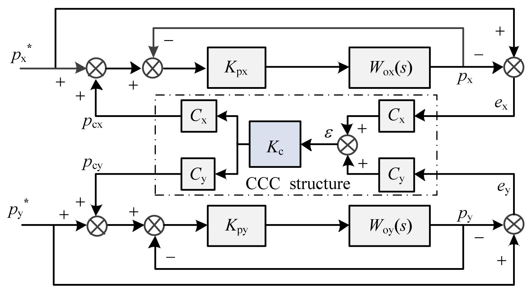
2. Contour Errors of Traditional Dual Motor System

In the position tracking process of the dual-PMSM system, the two main trajectories were the linear position trajectory and the curve position trajectory. A schematic diagram of the contour errors of the linear position trajectory and the curve position trajectory are shown in Figure 1.
In Figure 1, p* is the point of reference position trajectory, p is the point of actual position trajectory, β is the angle between the position trajectory tangential speed and x-axis positive direction, |pp*| is the tracking error e, and R is radius of the curve position trajectory.
From Figure 1a, the x-, y-axis tracking errors, ex, ey, and the contour error, ε, of the linear position trajectory can be expressed as:
e x = p x p x ,   e y = p y p y
ε = e x C x + e y C y
where Cx = −sin β, Cy = cos β.
Similarly, x-, y-axis tracking errors, ex, ey, and the contour error, ε, of the curve position trajectory can be expressed as:
e x = p x p x ,   e y = p y p y
ε = e x C x + e y C y
where Cx = −sin β + ex/2R, Cy = cos β + ey/2R.
The traditional dual-PMSM system usually adopts a position, velocity, and current three-closed-loop structure and combined with a cross-coupling control structure to control two motors. The contour error, ε, is calculated by the cross-coupling controller and feeds the output of CCC to the position loop of each motor, which is used to achieve to coordinated control of two motors. The control block diagram is presented in Figure 2.
In Figure 2, px* and py* are the reference position of each motor. px and py are the actual positions of each motor. pcx and pcx are the position compensation values of each motor after adding the cross-coupling structure. Kpx and Kpy are the proportional coefficients of the position loop. Wox(s) and Woy(s) are the position control system of motors. Kc is the gain coefficient of the cross-coupling controller.
According to Figure 2, the position tracking errors of the traditional dual-PMSM system can be obtained as follows:
e x = 1 1 + K px W ox ( s ) p x * ε K c C x K px W ox ( s ) 1 + K px W ox ( s )
e y = 1 1 + K py W oy ( s ) p y * ε K c C y K py W oy ( s ) 1 + K py W oy ( s )
It can be seen from Equations (5) and (6) that as Kc gradually increases, the position tracking errors, and the contour error are smaller under the premise that the system stability is guaranteed. Nevertheless, when Kc is too large, the position tracking precision of servo system decreases. In addition, when the reference position signal is, the high-order signa and the tracking speed of position will be limited by the proportional coefficients, Kpx and Kpy, which makes it difficult to achieve fast and precise tracking control of the desired position trajectory.

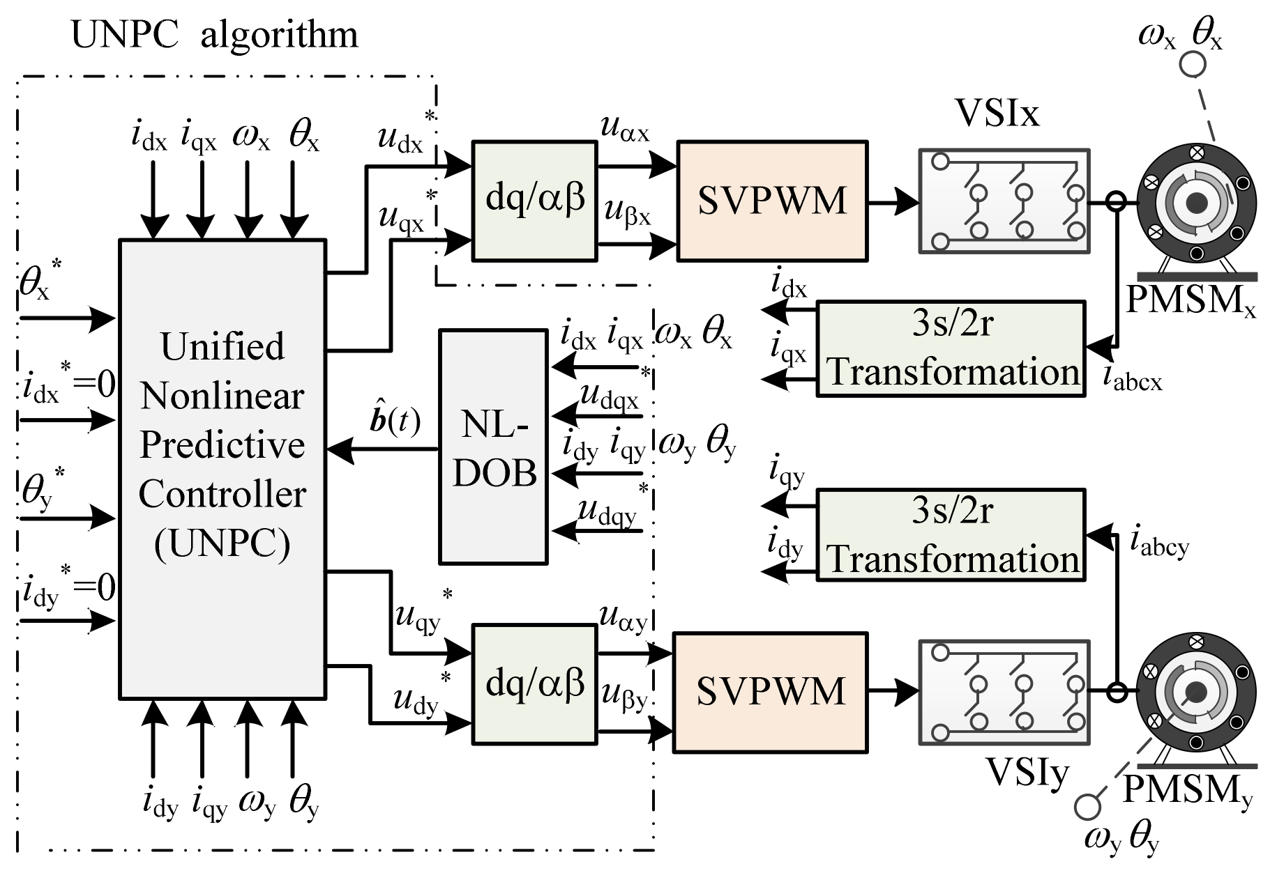
3. Design of UNPC System

In order to simplify the structure of traditional dual-PMSM system and achieve fast and high-precision cooperative control of the position trajectory, the PMSMs of dual motor systems are treated as a whole to establish a unified nonlinear model, and a compact controller of double motors is designed by UNPC algorithm. The structural diagram of the UNPC system is shown in Figure 3.

3.1. Mathematical Model of PMSM Systems

The mathematical model of the dual-PMSM system in the d–q rotor reference frame can be expressed in the nonlinear form as
x ˙ ( t ) = f ( x ) + g 1 ( x ) u ( t ) + g 2 ( x ) b ( t ) y ( t ) = h ( x )
where x = (idx, iqx, ωx, θx, idy, iqy, ωy,θy)T are the vectors of the states (the d-axis and the q-axis components of the armature current and rotor speed and rotational angel of the motors), u = (udx, uqx, udy, uqy)T are the control input vectors (the d-axis and q-axis components of the motor’s stator voltage), y = (idx, θx, idy, θy)T are the output vectors (the d-axis components of the armature current and the rotational angel of motors), b represents the disturbances caused by the parameter mismatch of motors and load torque, and b is given by
b ( t ) = b dx b qx b ω x b θ x b dy b qy b ω y b θ y T
For the PMSMs, f(x), g1(x), and g2(x) are defined as:
f ( x ) = f x f y T g 1 ( x ) = g 11 0 4 × 2 0 4 × 2 g 11 g 2 ( x ) = I 4 × 4 0 4 × 4 0 4 × 4 I 4 × 4
where I4×4 is the identity matrix, 04×2 and 04×4 are the zero matrix, fi (i = x, y), and g11 are given by:
f i = 1 L s ( R s i d i + p ω i L s i q i ) 1 L s ( R s i q i p ω i ( ψ f + L s i d i ) ) 1 J m ( 1.5 p ψ f i q i B ω i ) ω i , i x , y
g 11 = 1 L s 0 0 0 0 1 L s 0 0 T
In Equations (10) and (11), i = x, y represent the motors of the x- and y-axis. Rs, Ls, ψf, p, Jm, and B are the stator resistance, inductance, rotor permanent magnetic flux, pole pairs, inertia, and friction coefficient of the motor, respectively.
Define pi as the displacement of the end device of individual motor, Θi is the movement of the end device of every motor when the motor rotates one turn; then, there is
p i = Θ i 2 π θ i

3.2. Design of Nonlinear Disturbance Observer

In order to achieve high-precision control of the position tracking of the dual-PMSM system, the b(t) should be obtained through real-time computing, which is used for the feed-forward compensation control.
Based on the PMSMs system model, the NL-DOB is designed as follows [22]:
z ˙ = L z L ( f ( x ) + g 1 ( x ) u ( t ) + q ( x ) ) b ^ = z + q ( x )
where b ^ is the disturbance observation value, q(x) is the nonlinear function which needs to be designed, z is the internal state variable of the NL-DOB, and the gain L of the NL-DOB is given by:
L = q ( x ) x
The nonlinear function q(x) can be designed as:
q ( x ) = L x
where L = diag(ld, lq, lω, lθ, ld, lq, lω, and lθ) and ld, lq, lω, and lθ are the constants.
Considering that the control period of the PMSM is short enough, and the disturbance b(t) is assumed to change slowly and is bounded, so that:
b ˙ ( t ) = 0
Thus, the disturbance observation error of the NL-DOB can be defined as:
e b ( t ) = b ( t ) b ^ ( t )
The derivative of the Equation (17) with respect to time, we can get:
e ˙ b ( t ) = L e b ( t )
The Lyapunov function is defined as:
V b = e b T P b e b
where Pb is a real positive definite symmetric matrix, and Pb = diag(p1, p2, p3, p4, p5, p6, p7, and p8). By taking derivative of (19) with respect to time, we can get
V ˙ b = e b T P b e ˙ b + e ˙ b T P b e b = e b T P b L L T P b e b
For the NL-DOB designed by Equation (13), when Equation (20) satisfies the non-positive definite condition by designing L (ld, lq, lω, and lθ > 0), the disturbance observer is asymptotically stable. That is, when t → ∞, eb = 0.
In the practical applications, to ensure that b ^ ( t ) will converge to b(t) as soon as possible, a suitable L needs to be designed. For this reason, the time constants of the observer shown in Equation (13) is deduced, and the parameters design principle of NL-DOB are given by
1 l d s + 1 = 0 1 l q s + 1 = 0 1 l ω s + 1 = 0 1 l θ s + 1 = 0
Based on (21), it can be seen that the time constants of the NL-DOB are 1/ld, 1/lq, 1/lω, and 1/lθ, respectively. And the poles of observer are −ld, −lq, −lω and −lθ, respectively Therefore, when the absolute values of ld, lq, lω, and lθ are larger, the response speed of the observer is faster. Nevertheless, the absolute values of ld, lq, lω, and lθ are too large, which will cause measurement noise in a certain extent.
To ensure the estimation accuracy of the NL-DOB, the poles of observer are usually assigned 2~5 times of the system poles. Thus, combined with Equation (26), the sizing of the observer’s parameters is given by
l d = l q = ( 2 5 ) 3 2 T 1 l ω = l θ = ( 2 5 ) 1.95 T 2

3.3. Design of Unified Nonlinear Predictive Controller

To make the actual outputs tracking the reference inputs as fast and accurate as possible and reduce the contour error of dual-PMSM system, the cost function is defined as:
J = 1 2 0 T 1 E 1 T ( t + τ ) E 1 ( t + τ ) d τ + 1 2 0 T 2 E 2 T ( t + τ ) E 2 ( t + τ ) d τ + 1 2 0 T 2 ε T ( t + τ ) ε ( t + τ ) d τ
where T1 and T2 represent the predictive horizon of the current-loop and the position-loop, respectively. E1(t + τ) is the tracking error of d-axis current, E2(t + τ) is the tracking error of the rotational angel of motors, and ε(t + τ) is the contour error, and E1, E2, and ε are given by:
E 1 = i dx * i dx i dy * i dy T E 2 = θ x * θ x θ y * θ y T ε = C E 2
where C = (Cx Cy) is the gain matrix of the contour error. i dx * and i dy * are the reference values of the d-axis current of the x-, y-axis motor, θ x * and θ y * are the reference values of the rotational angel of the x-, y-axis motor.
According to (23) and (24), the cost function can be rewritten as:
J = 1 2 0 T 1 E 1 T ( t + τ ) E 1 ( t + τ ) d τ + 1 2 0 T 2 E 2 T ( t + τ ) ( I + C T C ) E 2 ( t + τ ) d τ
where I is the identity matrix.
In order to obtain the control law of the unified nonlinear predictive controller, according to the Taylor series expansion, idi(t + τ) and θi(t + τ) (i = x, y) are expressed as:
i d i ( t + τ ) = H 1 Y 1 i θ i ( t + τ ) = H 2 Y 2 i
where:
H 1 = 1 τ ,   H 2 = 1 τ τ 2 2 ! τ 3 3 ! , Y 1 i = i d i ( t ) i ˙ d i ( t ) T ,   Y 2 i = θ i ( t ) θ ˙ i ( t ) θ ¨ i ( t ) θ i ( t ) T
Similarly, i d i * (t + τ) and θ i * (t + τ) (i = x, y) can be approximated as:
i d i * ( t + τ ) = H 1 Y 1 i * θ i * ( t + τ ) = H 2 Y 2 i *
where:
Y 1 i * = i d i * ( t ) i ˙ d i * ( t ) T ,   Y 2 i * = θ i * ( t ) θ ˙ i * ( t ) θ ¨ i * ( t ) θ i * ( t ) T .
According to the theory of Lie derivative [23], the derivatives of the outputs with respect to time can be derived as:
i ˙ d i = L f i d i + L g 1 i d i u ( t ) + L g 2 i d i b ( t ) θ ˙ i = L f θ i + L g 2 θ i b ( t ) θ ¨ i = L f 2 θ i + L g 2 L f θ i b ( t ) θ i = L f 3 θ i + L g 1 L 2 f θ i u ( t ) + L g 2 L 2 f θ i b ( t )
From Equations (25)–(27), the cost function can be expressed as follows:
J = 1 2 0 T 1 Y ¯ 1 * Y ¯ 1 T Γ 1 T Γ 1 Y ¯ 1 * Y ¯ 1 d τ + 1 2 0 T 2 Y ¯ 2 * Y ¯ 2 T Γ 2 T I + C T C Γ 2 Y ¯ 2 * Y ¯ 2 d τ
where:
Y ¯ 1 * = Y 1 x * Y 1 y * ,   Y ¯ 1 = Y 1 x Y 1 y ,   Γ 1 = H 1 0 1 × 2 0 1 × 2 H 1 ,   Y ¯ 2 * = Y 2 x * Y 2 y * ,   Y ¯ 2 = Y 2 x Y 2 y ,   Γ 2 = H 2 0 1 × 4 0 1 × 4 H 2
Substituting (25)–(28) into (29), and solving δJu = 0, the control law of the dual-PMSM system were obtained as:
u ( t ) = G ( x ) 1 j = 0 1 δ j 1 ( L f j i dx i dx * ( j ) ) + K 1 b ( t ) j = 0 1 δ j 1 ( L f j i dy i dy * ( j ) ) + K 2 b ( t ) j = 0 3 δ j 3 ( L f j θ x θ x * ( j ) ) + K 3 b ( t ) j = 0 3 δ j 3 ( L f j θ y θ y * ( j ) ) + K 4 b ( t )
where:
G x = 1 L s 0 0 0 0 0 1 L s 0 0 1.5 p ψ f J m L s 0 0 0 0 0 1.5 p ψ f J m L s ,   δ 0 1 = 3 2 T 1 δ 1 1 = 1 δ 0 3 = 21 2 T 2 3 δ 1 3 = 42 5 T 2 2 δ 2 3 = 7 2 T 2 δ 3 3 = 1 , K 1 = 1 0 0 0 0 0 0 0 ,   K 2 = 0 0 0 0 1 0 0 0 , K 3 = 0 1.5 p ψ f J m 7 2 T 2 B J m 42 5 T 2 2 0 1 × 4 ,   K 4 = 0 1 × 4 0 1.5 p ψ f J m 7 2 T 2 B J m 42 5 T 2 2 .
In order to obtain the robust controller of dual-PMSM system that can suppress the disturbances, we substituted the estimated disturbances value b ^ ( t ) by the NL-DOB in Equation (13) into Equation (30), and we can obtained:
u ( t ) = G ( x ) 1 j = 0 1 δ j 1 ( L f j i dx i dx * ( j ) ) + K 1 b ^ ( t ) j = 0 1 δ j 1 ( L f j i dy i dy * ( j ) ) + K 2 b ^ ( t ) j = 0 3 δ j 3 ( L f j θ x θ x * ( j ) ) + K 3 b ^ ( t ) j = 0 3 δ j 3 ( L f j θ y θ y * ( j ) ) + K 4 b ^ ( t )

4. Stability Analysis and Parameters Tuning
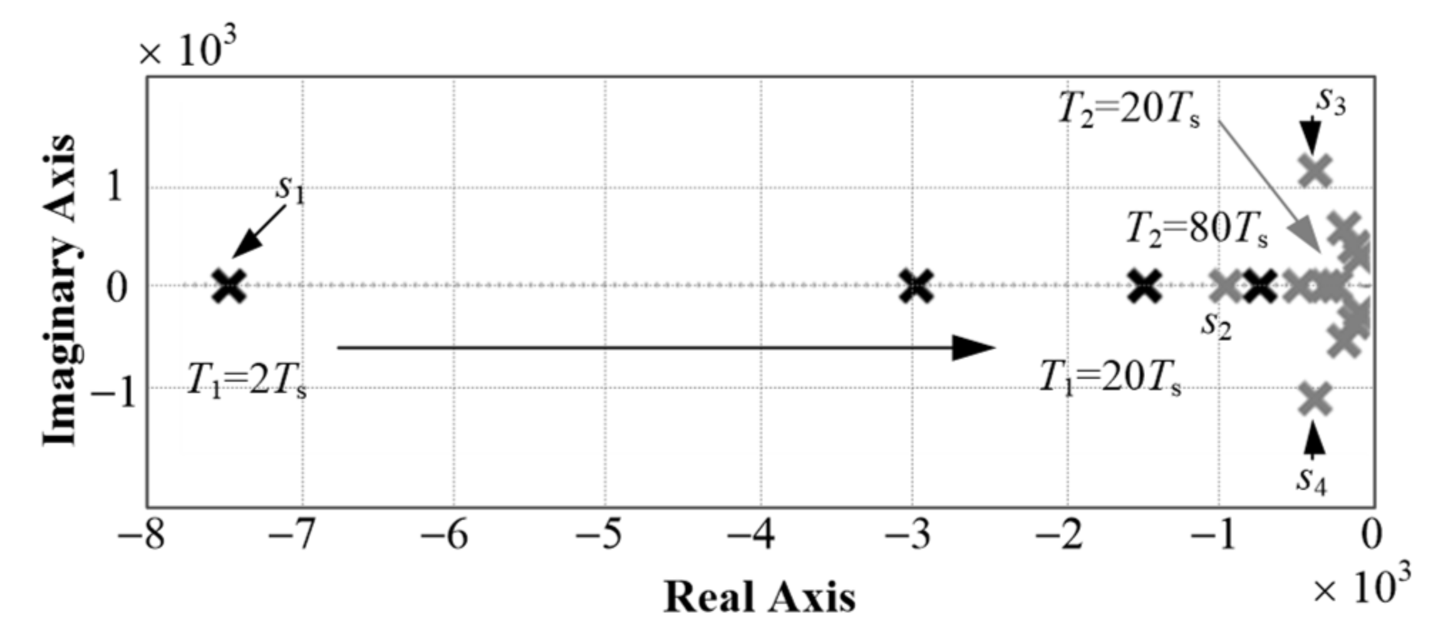
To analyze the stability of the closed-loop system, substituting Equation (31) into Equation (7), the characteristic Equation of the closed-loop system could be obtained as:
s + δ 0 1 = 0 s 3 + δ 2 3 s 2 + δ 1 3 s + δ 0 3 = 0
Based on (32), the eigenvalues of the closed-loop system are given by:
s 1 = 3 2 T 1 s 2 = 1.95 T 2 , s 3 , 4 = 0 . 774 ± j 2 . 19 T 2
Considering that the prediction horizon T1 and T2 are positive, the real parts of the closed-loop eigenvalues of the UNPC system are negative. Thus, the system is asymptotically stable.
The change årule of the closed-loop poles with the predictive horizon T1 and T2 can be presented in Figure 4. It should be noted that s1 is the current pole, s2 and s3,4 are the position poles, and the direction of the arrow represents the increasing direction of T1 and T2. Then, we can know that:
(1)
With the increasing in the T1 and T2, the poles s1, s2, and s3,4 will continue to approach the imaginary axis, the dynamic response speed of the system will slow down, and the stability of the system will deteriorate;
(2)
The position poles s3,4 are closer to the imaginary axis than the pole s2. That is, when the T2 changes, the poles s3,4 will play a dominant role in the position tracking performance.
(3)
With the increasing in T1 and T2, the position poles s3,4 are closer to the imaginary axis than the current pole s1, that is, the position response speed is slower than the current response speed of the PMSM control system. Thus, the corresponding requirement is T2 > T1.
In summary, the values of T1 and T2 should not be selected too large, so that it ensures the system has a better dynamic performance and certain stability.

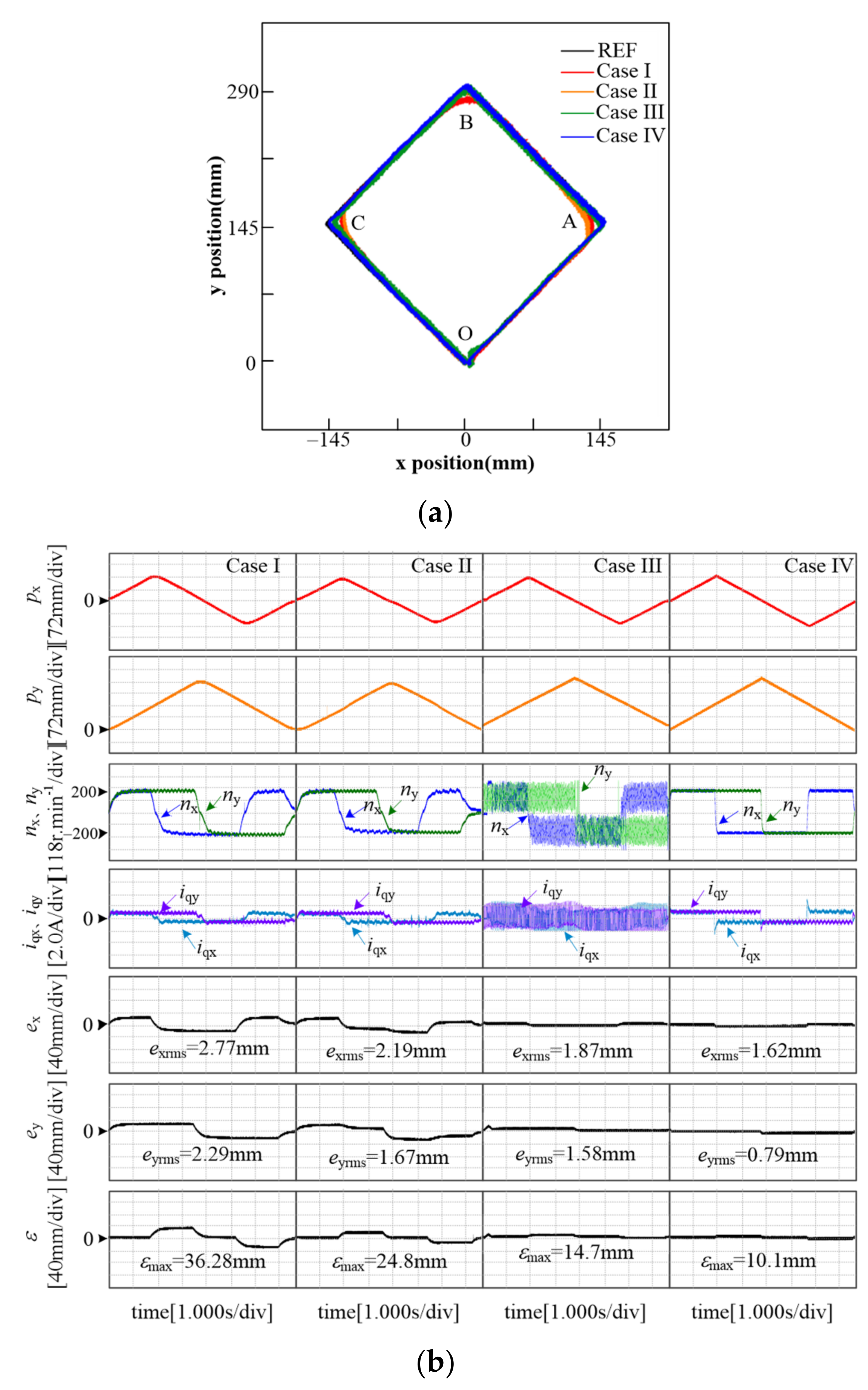
5. Experimental Verification

To verify the feasibility of the proposed UNPC algorithm, the experiments were carried out on an experimental platform with a two 2.3 kW surface mounted PMSM system driving the end devices of the motors to achieve position control. The parameters of the PMSM system are shown in Table 1. In the experiments, the control algorithm was implemented with the TMS320F28377D DSP produced by TI, and Cyclone V FPGA produced by Intel. DSP was used to execute the algorithm, and FPGA was used to implement the high-precision analog-to-digital conversion (ADC) sampling, digital-to-analog conversion (DAC) conversion, and PWM pulse generation. The switching frequency of the IPM was 10 kHz, and the sampling period of the system was 100 μs.
In the experiments, the control period Ts as 100 μs, and the prediction horizon T1 and T2 were 20 and Ts, respectively. The tracking performance of the position trajectory was evaluated by means of the maximum value of the contour error, εmax, and the mean value of the steady-state error, δrms, and the calculating formulas were as follows:
ε max = max k ε k
δ rms = k = 1 n δ 2 k n
where δ(k) means x-axis tracking error ex(k), y-axis tracking error ey(k), contour error ε(k) at kTs.
Then, the q-axis current standard deviation, σq, was used to evaluate its performance, and the calculating formula is given by:
σ q = 1 n 1 k = 1 n ξ k ξ ¯ 2
where ξ ¯ = 1 n k = 1 n ξ k , n is the number of sampling points.

5.1. Linear Trajectory Comparative Experiments

In order to verify that the control strategy proposed in this paper had a better position tracking precision at the turning point of the trajectory, the constant velocity tracking experiment was conducted. The diamond position trajectory with O point as the starting point was given to the dual-PMSM system: O (0, 0) → A(145, 145) → B(0, 290) → C(−145, 145) → O(0, 0), The proposed UNPC strategy (Case IV) was compared with the traditional PI single-axis decoupling control strategy (Case I), and cascade PI-CCC control strategy (Case II), and the cascade predictive method [19] (Case III). The experimental results are shown in Figure 5.
The curves of diamond position trajectory of three control strategies are given in Figure 5a. The experimental waveforms of the positions px, py, the speeds of motors nx, ny, q-axis currents, iqx, iqy, position tracking errors, ex, ey, and contour error, ε, are given in Figure 5b.
It can be seen from Figure 5 that compared with the traditional control strategy, the dynamic performance of the speed of motors and the steady-state performance of the q-axis current were significantly improved when adopting the proposed UNPC strategy in this paper. When the PI single-axis decoupling control strategy was adopted, the mean values of the steady-state tracking errors of the x-, y-axis position and the maximum contour error (εmax) were 2.77, 2.29, and 36.28 mm, respectively. When the PI-CCC control strategy was adopted, the mean values of the steady-state tracking errors of the x-, y-axis position and the maximum contour error (εmax) are 2.19, 1.67, and 24.8 mm, respectively. When Case III was adopted, the mean values of the steady-state tracking errors of the x-, y-axis position and the maximum contour error (εmax) were 1.87, 1.58, and 14.7 mm, respectively. Nevertheless, adopting the UNPC strategy, the mean values of the steady-state tracking errors of the x-, y-axis position and the maximum contour error (εmax) were 1.62, 0.79, and 10.1, respectively. Through the above experimental results, it can be known that compared with the traditional PI single-axis decoupling control strategy, the UNPC control strategy can reduce the mean values of the steady-state tracking errors of the x-, y-axis position and the maximum contour error (εmax) by 41.5%, 65.5%, 72.1%, and compared with the PI-CCC control strategy, the UNPC control strategy can reduce the mean values of the steady-state tracking errors of the x-, y-axis position and the maximum contour error (εmax) by 26.0%, 52.1%, and 59.25%, and compared with Case III, the UNPC control strategy can reduce the mean values of the steady-state tracking errors of the x-, y-axis position and the maximum contour error, εmax, by 13.36%, 50.0%, and 31.29%. Hence, when utilizing the UNPC strategy, the output trajectory can track the desired trajectory accurately and the position tracking effect is better.

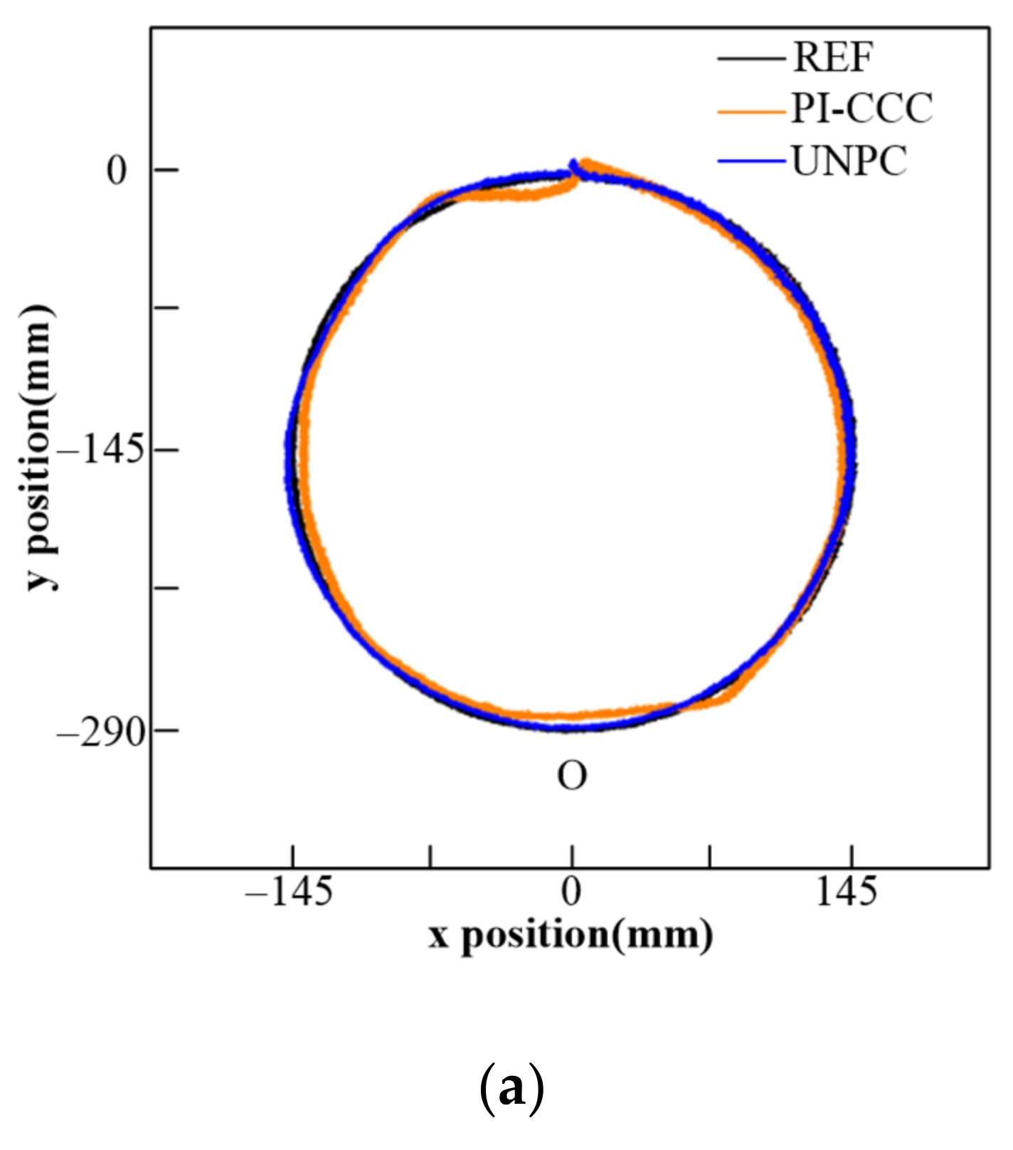
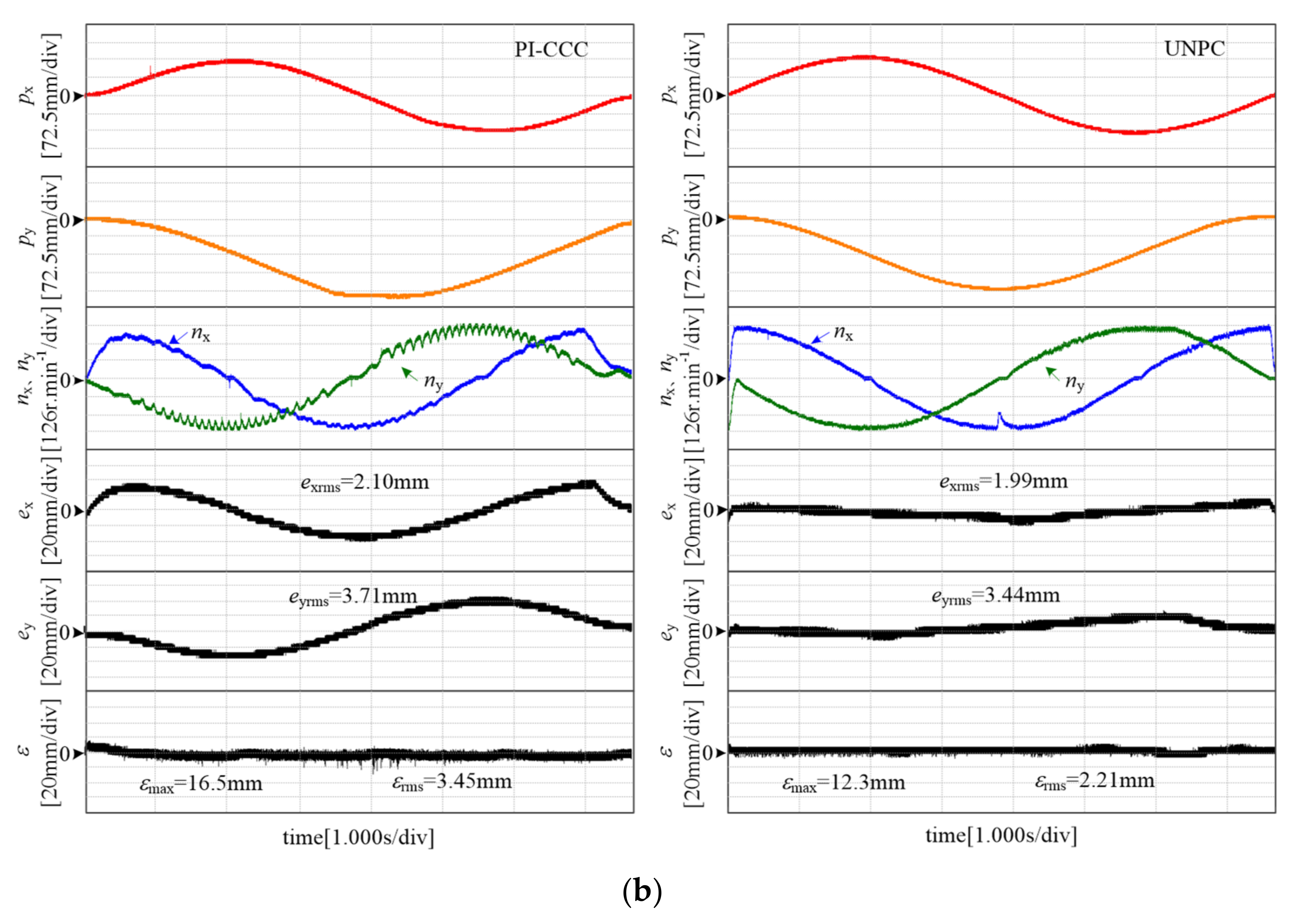
5.2. Circular Trajectory Experiments

The circular position trajectory with the origin O as the starting point. Meanwhile, the proposed UNPC control strategy was applied, and the corresponding experimental results are shown in Figure 6.
The formula of the circular reference trajectory is:
x = 145 sin t ( mm ) y = 145 cos t 145 ( mm )
The contour error calculating formula is:
ε = 145 p x 2 + ( p y + 145 ) 2
As shown in Figure 6, the speed of two motors can make real-time changes along with the reference position. In addition, when the traditional PI-CCC was adopted, the maximum contour error (εmax) and the mean values of the contour error (εrms) were 16.5 mm and 3.45 mm, respectively. Nevertheless, when the proposed UNPC was applied, the maximum contour error (εmax) and the mean values of the contour error (εrms) were 12.3 mm and 2.21 mm, respectively. Thus, compared with the PI-CCC control strategy, the proposed UNPC can reduce the maximum contour error (εmax) and the mean values of the contour error (εrms) by 25.5% and 35.9%. The above phenomenon shows that the proposed UNPC can more accurately track the s trajectory than the PI-CCC method.

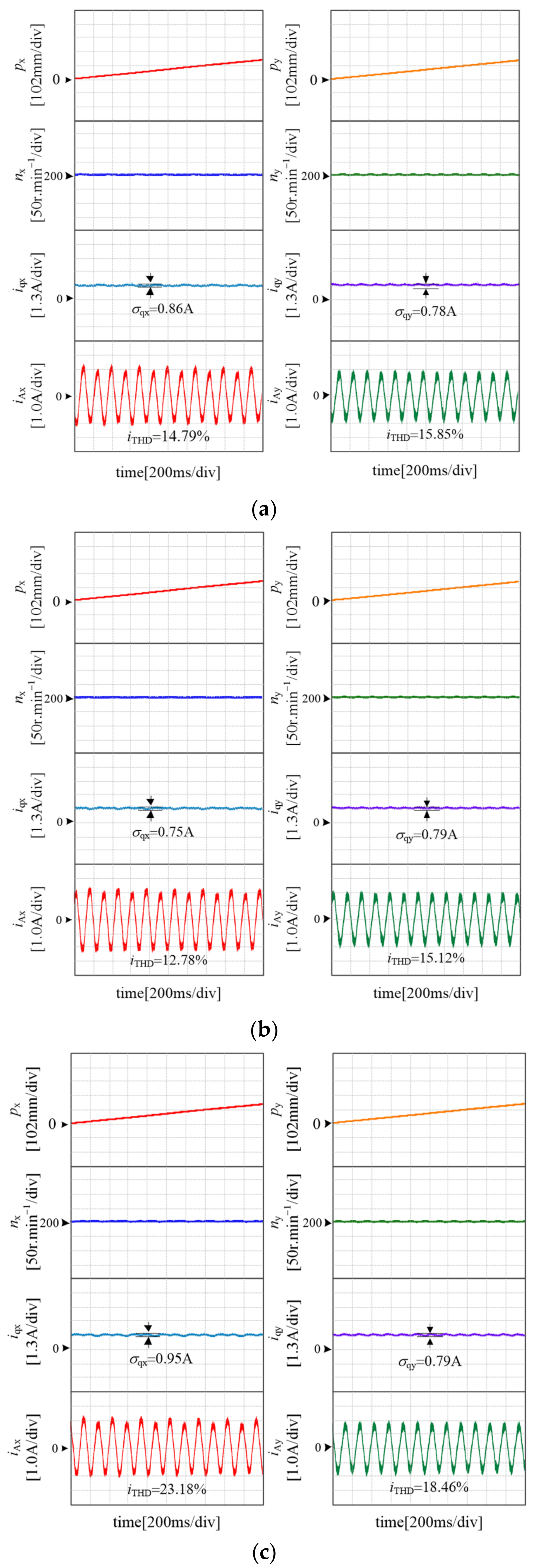
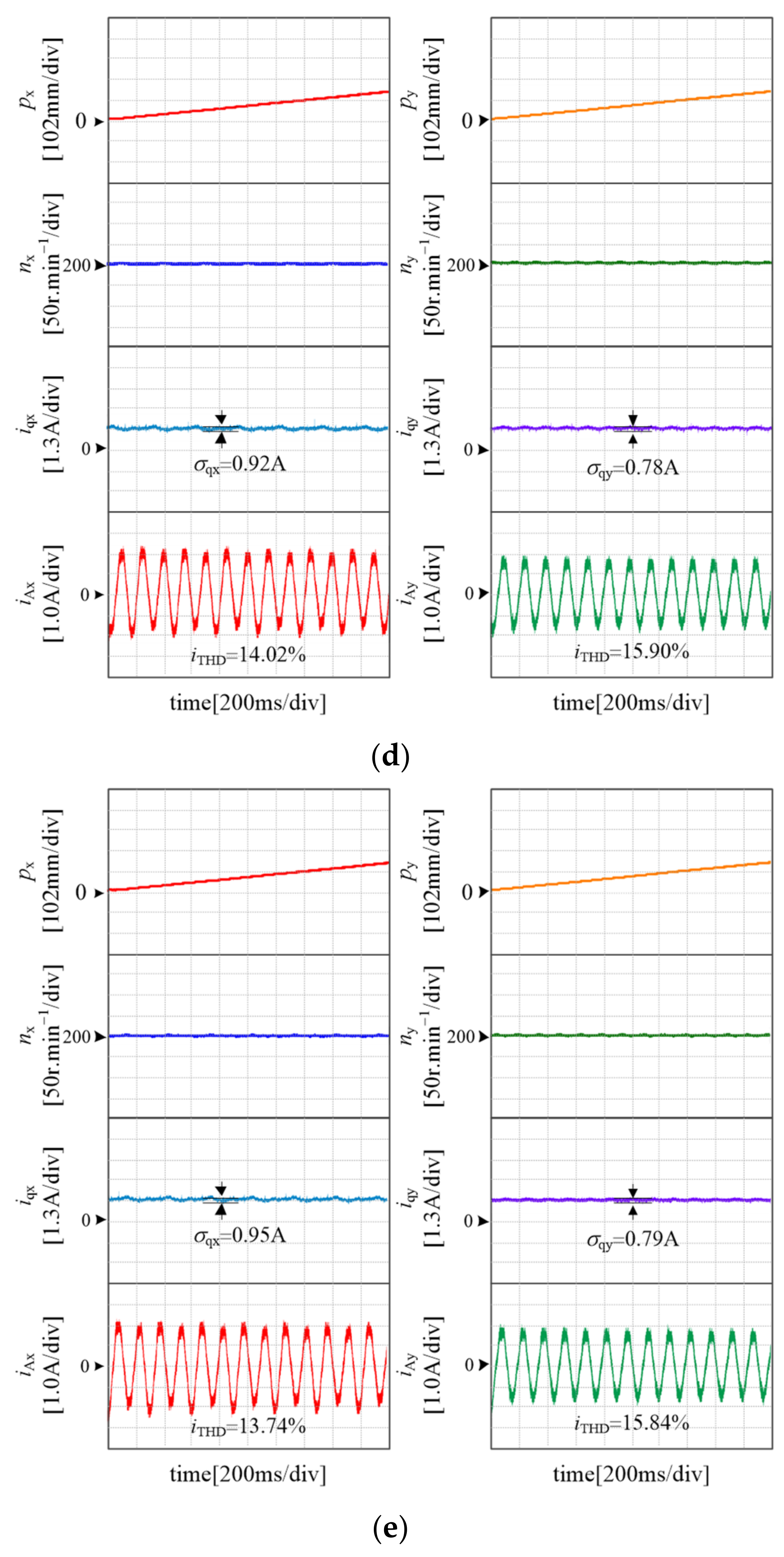
5.3. Motor Parameters Mismatch Experiment

In order to verify the control performance of the UNPC strategy under the condition of motor’s parameters mismatch, the parameters mismatch experiments were implemented by setting inertia, Jm, stator inductance, Ls, and stator resistance, Rs, in the controller are equal to 1.0 Jm, 1.0 LS, 1.0 Rs, 0.8 Jm, 0.8 LS, 0.8 Rs, and 1.2 Jm, 1.2 LS, and 1.2Rs, respectively. Let the dual motor system follow the 45° slope position signal, the experimental results are shown in Figure 7.
By comparison with Figure 7a–e, it can be seen that each motor can track the reference position smoothly under the condition of motor parameter mismatch. At the same time, the steady-state performance of speed is better, and the standard deviations (σq) of the q-axis current and the harmonic content of stator current change slightly. The experimental results indicate that the designed controller in this paper has a good steady-state control performance in case of that the motor’s parameters are mismatch.

6. Conclusions

To improve the position control performance of dual-PMSMs system, a UNPC strategy based on the unified modeling of the double PMSMs is proposed in this paper. On the one hand, the single-loop controller of double motors was designed by solving the UNPC optimal control law, which can reduce the contour error of the dual-PMSMs system under the premise of ensuring the single-axis tracking precision. On the other hand, an NL-DOB is designed to estimate the uncertain disturbances that can weaken the influence of uncertain disturbances on the position trajectory tracking precision. The experimental results show that the proposed UNPC strategy is effective and feasible. In addition, the idea of UNPC can also be applied in the multi-motors drive system.

Author Contributions

Conceptualization, Z.Z.; Data curation, Z.X.; Formal analysis, G.Z.; Funding acquisition, Z.Z. and Q.G.; Investigation, G.Z.; Methodology, Z.Z.; Project administration, Z.Z.; Resources, Q.G.; Software, Z.X.; Supervision, G.Z. and Q.G.; Validation, Z.X.; Visualization, Z.X.; Writing—original draft, Z.X. All authors have read and agreed to the published version of the manuscript.

Funding

This research was funded by “The National Natural Science Foundation of China, grant number: 51907142 and 52077154” and “The Natural Science Foundation of Tianjin City, grant number: 20JCQNJC00030”.

Institutional Review Board Statement

Not applicable.

Informed Consent Statement

Not applicable.

Conflicts of Interest

The authors declare no conflict of interest.

References

  1. Liu, M.; Gu, F.; Huang, J.; Wang, C.; Cao, M. Integration design and optimization control of a dynamic vibration absorber for electric wheels with in-wheel motor. Energies 2017, 10, 2069. [Google Scholar] [CrossRef] [Green Version]
  2. Chen, W.; Liang, J.; Shi, T. Speed Synchronous Control of Multiple Permanent Magnet Synchronous Motors Based on an Improved Cross-Coupling Structure. Energies 2018, 11, 282. [Google Scholar] [CrossRef] [Green Version]
  3. Wu, Y.; Cheng, Y.; Wang, Y. Research on a Multi-Motor Coordinated Control Strategy Based on Fuzzy Ring Network Control. IEEE Access 2020, 8, 39375–39388. [Google Scholar] [CrossRef]
  4. Hanifzadegan, M.; Nagamune, R. Contouring Control of CNC Machine Tools Based on Linear Parameter-Varying Controllers. IEEE/ASME Trans. Mechatron. 2016, 21, 2522–2530. [Google Scholar] [CrossRef]
  5. Lie, T.; Landers, R.G. Multiaxis contour control—The state of the art. IEEE Trans. Control Syst. Technol. 2013, 21, 1997–2010. [Google Scholar]
  6. Corapsiz, M.F.; Erenturk, K. Trajectory tracking control and contouring performance of three-dimensional CNC. IEEE Trans. Ind. Electron. 2016, 63, 2212–2220. [Google Scholar] [CrossRef]
  7. Lou, Y.; Meng, H.; Yang, J.; Li, Z.; Gao, J.; Chen, X. Task Polar Coordinate Frame-Based Contouring Control of Biaxial Systems. IEEE Trans. Ind. Electron. 2014, 61, 3490–3501. [Google Scholar] [CrossRef]
  8. Wang, Z.; Hu, C.; Zhu, Y. Dynamical Model Based Contouring Error Position-Loop Feedforward Control for Multiaxis Motion Systems. IEEE Trans. Ind. Inf. 2019, 15, 4686–4695. [Google Scholar] [CrossRef]
  9. Li, M.; Zhu, Y.; Yang, K.; Hu, C.; Mu, H. An Integrated Model-Data-Based Zero-Phase Error Tracking Feedforward Control Strategy with Application to an Ultraprecision Wafer Stage. IEEE Trans. Ind. Electron. 2017, 64, 4139–4149. [Google Scholar] [CrossRef]
  10. Chu, Z.; Chen, G.; Cui, J.; Wang, S.; Sun, F. Classifier-Based Approximator for Friction Compensation in High Accelerated Positioning System. IEEE Trans. Ind. Electron. 2021, 68, 4090–4098. [Google Scholar] [CrossRef]
  11. Amthor, A.; Zschaeck, S.; Ament, C. High Precision Position Control Using an Adaptive Friction Compensation Approach. IEEE Trans. Autom. Control 2010, 55, 274–278. [Google Scholar] [CrossRef]
  12. Koren, Y. Cross-coupled biaxial computer for manufacturing systems. ASME J. Dyn. Syst. Meas. Control 1980, 102, 265–272. [Google Scholar] [CrossRef]
  13. Koren, Y.; Lo, C.C. Advanced controllers for feed drives. CIRP Ann. 1992, 41, 689–698. [Google Scholar] [CrossRef]
  14. Xu, W.; Hou, J.; Li, J.; Yuan, C.; Simeone, A. Multi-Axis Motion Control Based on Time-Varying Norm Optimal Cross-Coupled Iterative Learning. IEEE Access 2020, 8, 124802–124811. [Google Scholar] [CrossRef]
  15. Yang, X.; Seethaler, R.; Zhan, C.; Lu, D.; Zhao, W. A Model Predictive Contouring Error Precompensation Method. IEEE Trans. Ind. Electron. 2020, 67, 4036–4045. [Google Scholar] [CrossRef]
  16. Lam, D.; Manzie, C.; Good, M.C. Model Predictive Contouring Control for Biaxial Systems. IEEE Trans. Control Syst. Technol. 2013, 21, 552–559. [Google Scholar] [CrossRef]
  17. Shi, T.; Zhang, X.; Zhou, Z.; Xia, C. Precise Contour Control of Biaxial Motion System Based on MPC. IEEE J. Emerg. Sel. Top. Power Electron. 2018, 6, 1711–1721. [Google Scholar] [CrossRef]
  18. Tang, L.; Landers, R.G. Predictive contour control with adaptive feed rate. IEEE/ASME Trans. Mechatron. 2012, 17, 669–679. [Google Scholar] [CrossRef]
  19. Zhang, X.; Shi, T.; Wang, Z.; Geng, Q.; Xia, C. Generalized Predictive Contour Control of the Biaxial Motion System. IEEE Trans. Ind. Electron. 2018, 65, 8488–8497. [Google Scholar] [CrossRef]
  20. Wei, Y.; Wei, Y.; Sun, Y.; Qi, H.; Guo, X. Prediction Horizons Optimized Nonlinear Predictive Control for Permanent Magnet Synchronous Motor Position System. IEEE Trans. Ind. Electron. 2020, 67, 9153–9163. [Google Scholar] [CrossRef]
  21. Errouissi, R.; Ouhrouche, M.; Chen, W.; Trzynadlowski, A.M. Robust Nonlinear Predictive Controller for Permanent-Magnet Synchronous Motors with an Optimized Cost Function. IEEE Trans. Ind. Electron. 2012, 59, 2849–2858. [Google Scholar] [CrossRef]
  22. Chen, W.; Ballance, D.; Gawthrop, P.; Gribble, J. Nonlinear PID predictive controller. Proc. Inst. Elect. Eng.—Control Theory Appl. 1999, 146, 603–611. [Google Scholar] [CrossRef] [Green Version]
  23. Isidori, A. Nonlinear Control Systems: An Introduction, 3rd ed.; Springer: Berlin/Heidelberg, Germany, 1995. [Google Scholar]
Figure 1. Schematic diagram of the contour errors of the trajectory: (a) linear position trajectory; (b) curve position trajectory.
Wevj 12 00266 g001
Figure 2. Block diagram of the traditional dual-PMSM system.
Wevj 12 00266 g002
Figure 3. Structural diagram of the UNPC.
Wevj 12 00266 g003
Figure 4. The relationship between the predictive horizon and the poles distribution.
Wevj 12 00266 g004
Figure 5. Experimental comparison of traditional control strategy and UNPC: (a) output trajectory of diamond; (b) waveforms of steady-state experimental.
Wevj 12 00266 g005
Figure 6. Circular tracking experiment of PI-CCC and UNPC: (a) Output trajectory of circular; (b) waveforms of steady-state experiment.
Wevj 12 00266 g006aWevj 12 00266 g006b
Figure 7. Experimental results of UNPC under the condition of motor parameters mismatch: (a) 1.0 Jm, 1.0 LS, and 1.0 Rs; (b) 0.8 Jm, 0.8 LS; (c) 1.2 Jm, 1.2 LS; (d) 0.8 RS; (e) 1.2 RS.
Wevj 12 00266 g007aWevj 12 00266 g007b
Table 1. Parameters of the PMSM system.
ParametersSymbolValueUnits
Rated power PN2.3kW
Rated torqueTN15Nm
Number of pole–pairsp2-
Stator resistanceRs0.635Ω
Stator inductanceLs4.025mH
Permanent magnet fluxψf0.5Wb
InertiaJm0.00272kgm2
Friction coefficientB0.002-
Movement of the end Θi0.145m
Publisher’s Note: MDPI stays neutral with regard to jurisdictional claims in published maps and institutional affiliations.

