Article

A Position Sensorless Control Strategy for BLDCM Driven by FSTPI Based on Flux-Linkage Function

1
School of Electrical Engineering, Tiangong University, Tianjin 300387, China
2
Weichai Power Co., Ltd., Weifang 261061, China
3
Advanced Electrical Equipment Innovation Center, Zhejiang University, Hangzhou 311107, China
*
Author to whom correspondence should be addressed.
World Electr. Veh. J. 2022, 13(12), 238; https://doi.org/10.3390/wevj13120238
Submission received: 3 November 2022 / Revised: 27 November 2022 / Accepted: 6 December 2022 / Published: 9 December 2022
(This article belongs to the Special Issue Electrical Machines Design and Control in Electric Vehicles)

Abstract

:
This paper presents a new position sensorless control strategy for a brushless DC motor (BLDCM) driven by a four-switch three-phase inverter (FSTPI). This strategy introduces a flux-linkage function, which changes obviously at the time of the extremum jump. In the proposed strategy, the extremum jump edge determines the six commutation points needed for motor commutation. Then the high-precision and reliable commutation of the BLDCM is realized. This strategy can be used on BLDCM driven by FSTPI. Compared with other position sensorless control methods for BLDCM driven by FSTPI, the proposed method does not need to set a threshold value to detect the commutation point. It can obtain six commutation points required for motor commutation without interpolation. This avoids commutation errors caused by threshold value setting and interpolation. In addition, this strategy adopts a three-phase current control method for BLDCM driven by FSTPI. It can effectively restrain the current distortion of the capacitor middle point connection phase. And the terminal voltage is calculated. It can avoid the error caused by hardware sampling and improve the accuracy of the position sensorless control strategy. The experimental results verify the correctness of the theory and the effectiveness of the method.

1. Introduction

The brushless DC motor (BLDCM) has the characteristics of a simple structure, high torque, and high efficiency. It has been widely used in automobiles, medical, household appliances, industrial automation, office automation, and other fields [1,2,3]. The BLDCM usually needs a position sensor to obtain the motor rotor position. However, the installation of position sensors will increase the cost and size of the system and will reduce the reliability of the system. So the position sensors are not well adapted to various working situations [4,5]. Scholars have researched many position sensorless control methods, including the back EMF method, flux linkage estimation detection method, inductance method, and artificial intelligence method. These methods avoid the problems associated with position sensors.
There are many detection methods for position sensorless control technology. The most mature one is the back EMF method [6,7,8,9,10]. The back EMF method is a sensorless control method to determine the commutation point of the motor through the zero crossing point of the phase back EMF or the line-to-line back EMF. The back EMF method has the terminal voltage detection method, line-to-line back EMF method, back EMF integration method, and back EMF third harmonic method. In [6], the third harmonic flux linkage was applied to the high-speed BLDCM, and the phaselocked loop was used to correct the commutation error. In [7], it is proposed to detect the zero crossing point of back EMF under the action of zero vector and effective vector in the low-speed and high-speed, respectively. In [8], a resistance network composed of three resistors is used to obtain the virtual neutral voltage to get the ZCP of phase back EMF. In [9], a commutation compensation measure is proposed for the phase delay caused by the deep filtering of the back EMF, which improves the accuracy of the commutation. In [10], a self-correction control method based on model-free adaptive control is proposed using the relationship between commutation error and the voltage difference of the terminal voltage of the silent phase at the beginning and at the end of commutation. Although the back EMF method has been widely used and studied, it is not suitable for low-speed applications. The flux linkage estimation detection method [11,12,13,14,15] uses the measurable voltage and current to estimate the flux linkage. Then the position signal of the rotor is obtained according to the flux linkage. An improved rotor position observer is presented in [11], where the increment of the rotor position is achieved by combining the back EMF function with the calculated flux linkage increment. In [12], a direct control method of BLDCM is proposed, in which the terminal voltage of the floating phase is oriented along the Z axis perpendicular to the ABC plane. In [13], the commutation point can be directly obtained by comparing the flux linkage increment with the set threshold. In [14], a simplified flux equation has been used to estimate the rotor position, and the motor rotor position can be estimated from near zero to high speed. In [15], a speed-independent flux-function method was proposed, which can achieve good commutation accuracy at most speeds. The flux linkage is a physical quantity independent of the speed. The flux estimation detection method is theoretically independent of the speed of the motor. It can better detect the position of the motor rotor when the motor is at low speed. However, since the voltage must be integrated in the calculation of flux linkage, the method will generate cumulative errors. The inductance method [16,17,18,19] is a method to judge the rotor position by using the rotor salient pole effect and the stator core saturation effect, which causes the inductance to change. It is more suitable for detecting the rotor position at low speed and rest. In [16], the relationship between the inductance is obtained by comparing the magnitude of the nonconducting phase voltage when the voltage vector acts to determine the initial position of the rotor. In [17], the relationship between inductance is obtained by comparing the magnitude of the nonconducting phase voltage when the voltage vector acts and the diode freewheeling is disconnected. In [18], high-frequency signals are coupled into the motor windings to detect the motor inductance and determine the initial rotor position. In [19], the initial position of the rotor is obtained by detecting the inductance utilizing a DC-link voltage sensor. This method compensates for the fact that the back EMF method and the flux linkage estimation detection method cannot be used when the motor is stationary. But the inductance method is not suitable for the high-speed case. The artificial intelligence method obtains the rotor position information through artificial intelligence algorithms such as genetic algorithm, neural network algorithm, fuzzy control, ant colony algorithm, and so on, to realize the sensorless position control. This method can make the motor obtain better performance, and with the continuous development of digital chips, the implementation of artificial intelligence algorithms is easier.
In recent years, the FSTPI had the advantages of a few switches and low hardware costs. It can provide fault tolerant control for power switch open circuit faults in the traditional six-switch three-phase inverter (SSTPI) and one-phase open circuit faults in motor drive systems. It has been widely studied by many scholars at home and abroad [20,21]. However, the above position sensorless methods are proposed for a BLDCM driven by SSTPI. Those methods can not be directly applied to BLDCM driven by FSTPI. At present, there are relatively few control methods applicable to BLDCM driven by FSTPI. In [22], the two commutation points of the motor are obtained by detecting the two terminal voltages of a-phase and b-phase. The intersection point of the two terminal voltages corresponds to the commutation point, thus realizing position sensorless control. But this method can only get two commutation points, and the other four commutation points need to be obtained by interpolation. In [23], a position sensorless control method is proposed. The method establishes three voltage functions by detecting the phase voltages uao, and ubo, and the zero crossing point of the voltage function corresponds to the commutation point of the motor. This method does not need to determine the commutation point of the motor by shifting the phase by 30 electrical degrees or 90 electrical degrees. However, this method uses a low-pass filter to eliminate the high-frequency noise signal in the phase voltage. And this method neglects the voltage drop on the resistance and inductance. It leads to inaccurate position detection and bigger errors in the case of low speed, heavy load, and unsatisfactory commutation current. Three error functions are introduced in [24]. Six commutation points are obtained by detecting the zero crossing point of the error function and then delaying 30 electrical degrees. This method needs to collect the nonconducting phase voltage. It can not use when the freewheeling commutation angle exceeds 30 electrical degrees at high speed. And the current of the capacitor middle point connection phase of the FSTPI is uncontrollable. This method does not consider the resistance and inductance voltage drop of the capacitor middle point connection phase, and there is some error. In addition, there are some position sensorless control methods for PMSM driven by FSTPI. In [25], a position sensorless speed control method based on stator feedforward dq-axes voltage control has been proposed for PMSM driven by FSTPI. This method is simpler, more effective, and leads to a lower implementation processing time, but its control is more complex and not suitable for BLDCM, where the control method is simple. In [26], a simple and smooth zero-angle rotor initial position alignment scheme using a low-frequency signal injection that is applied to the d-axis voltage reference is proposed for PMSM driven by FSTPI. However, this method cannot detect the rotor position in real-time during the operation of the motor.
This paper presents a position sensorless control method for a BLDCM driven by FSTPI based on the flux-linkage function. This method adopts a three-phase conduction current control method to restrain current distortion for a BLDCM driven by FSTPI. Six commutation points are determined without interpolation by constructing flux-linkage functions and selecting different flux-linkage functions under different operating modes. And the method does not need to set a threshold value to determine the commutation point, avoiding the error caused by the threshold value. This method does not have the problem that it cannot be used when the freewheeling commutation angle exceeds 30 electrical degrees at high speed. In the proposed strategy, the winding terminal voltage can be calculated by the switching state of the switch. It avoids the error caused by hardware sampling. The commutation point obtained is more accurate.

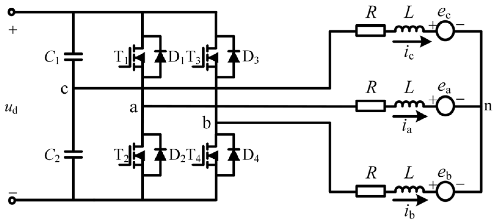
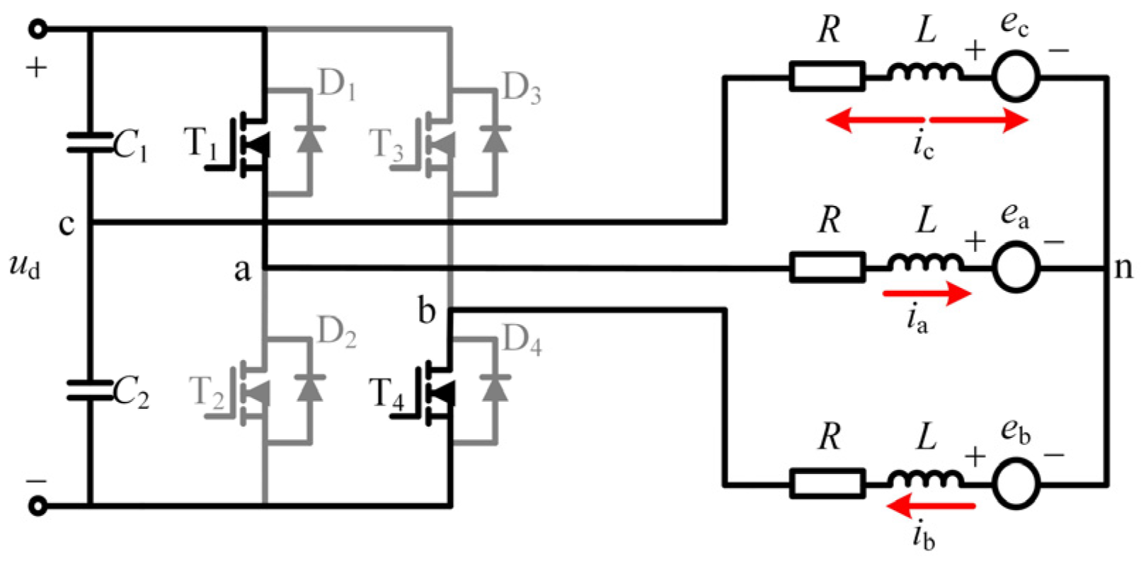
2. BLDCM Driven by FSTPI System

The equivalent circuit of the BLDCM driven by the FSTPI system is shown in Figure 1, where C1 and C2 are the DC-link capacitors.
In Figure 1, the c-phase of the BLDCM is connected to the middle point of the capacitor bridge arm. Its three-phase terminal voltage equation as
{ u a = R i a + L d i a d t + e a + u n u b = R i b + L d i b d t + e b + u n u c = R i c + L d i c d t + e c + u n
where R and L are the winding’s phase resistance and phase inductance, respectively, and im, um, em (m = a, b, c) represent three-phase current, three-phase terminal voltage, and three-phase back EMF, respectively.
The ideal back EMF, phase current, and Hall signal of a BLDCM are shown in Figure 2, where θ is the rotor’s electrical degree. Under ideal conditions, the back EMF is the trapezoidal wave, and the phase current is the square wave. According to the relationship between the back EMF and the phase current, one electrical cycle of the BLDCM driven by FSTPI can be divided into six operating modes. Each operating mode is 60 electrical degrees. As can be seen from the figure, the back EMF zero crossing point of BLDCM is ahead of the next commutation point by 30 electrical degrees.
In the ideal BLDCM drive, only two phases of each operating mode are conductive, and the other phase is not conducive. The phase current should appear rectangular to make the motor produce the maximum constant torque. The operating phase, expected current, and operating devices under the six operating modes are shown in Table 1, where I* is the expected current amplitude.
In the FSTPI, as the c-phase is connected to the middle point of the series capacitor, the current of the c-phase is uncontrollable. When the motor operates in modes I and IV, the c-phase is the nonconducting phase, and its expected current is zero. However, due to the influence of the back EMF of the c-phase, a circulating current is generated between the c-phase winding and other two-phase windings, causing current distortion. Because the BLDCM driven by the FSTPI system use the c-phase as the nonconducting phase, its back EMF can cause the current distortion. So direct current control for the BLDCM generally is used. That is, under mode I and mode IV, the currents of a-phase and b-phase are controlled as the expected current by independent hysteresis current regulators. It indirectly makes the nonconducting phase current zero. In mode I and mode IV, when the current ia is less than the reference current, control the power transistor T1 to conduct, and the current ia increases. When the current ia is greater than the reference current, control the power transistor T2 to conduct, and the current ia decreases. Similarly, when the current ib is less than the reference current, control the power transistor T3 to conduct, and the current ib increases. When the current ib is greater than the reference current, control the power transistor T4 to conduct, and the current ib decreases. When the motor operates in other modes, the c-phase is the conducting phase, and the a-phase or b-phase is the nonconducting phase. Therefore, the nonconducting phase current can be controlled to zero by turning off the bridge arm power transistor of the nonconducting phase in a-phase or b-phase. The conducting phase current can be made the reference value by hysteresis control of the bridge arm power transistor of the conducting phase.

3. Proposed Position Sensorless Control Method of BLDCM Driven by FSTPI

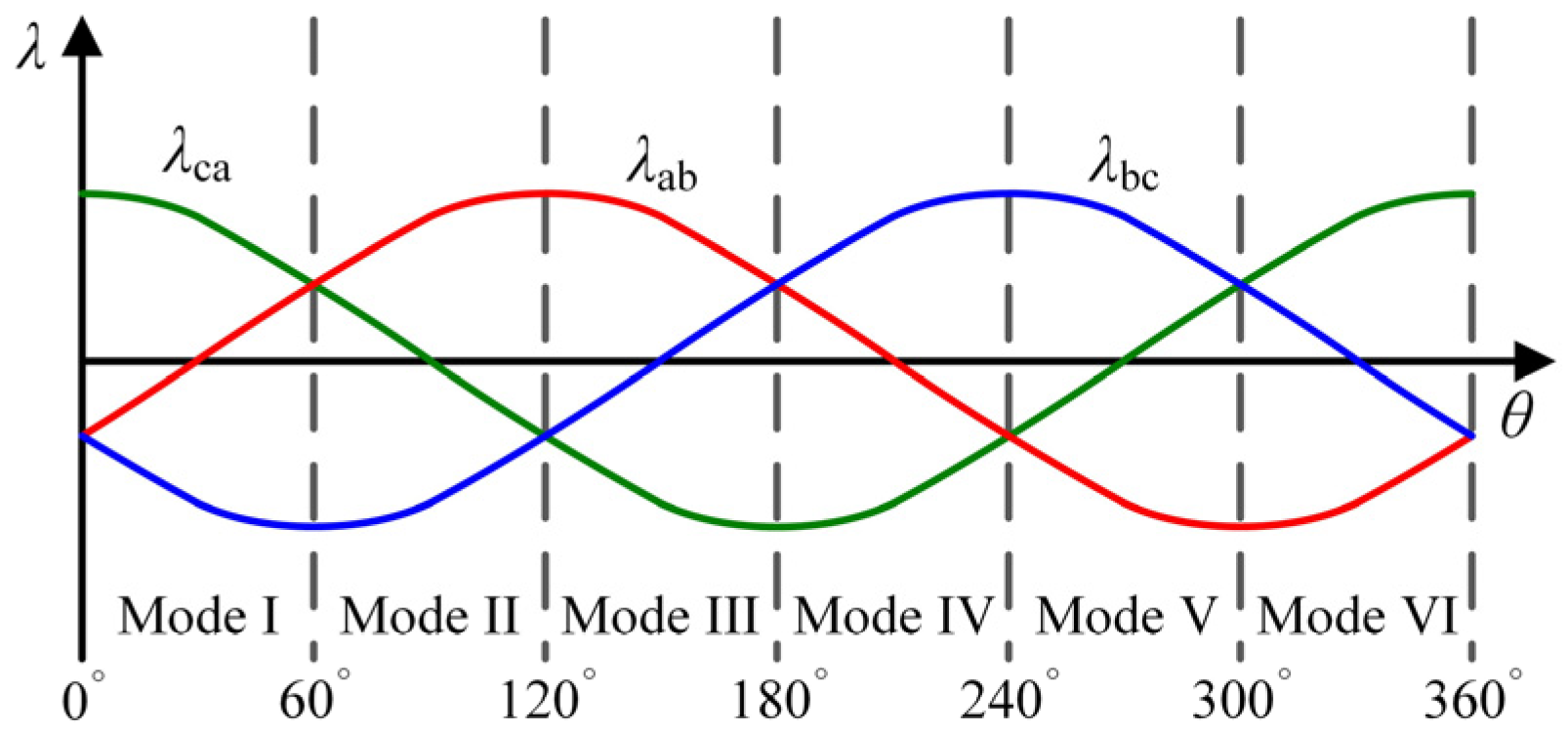
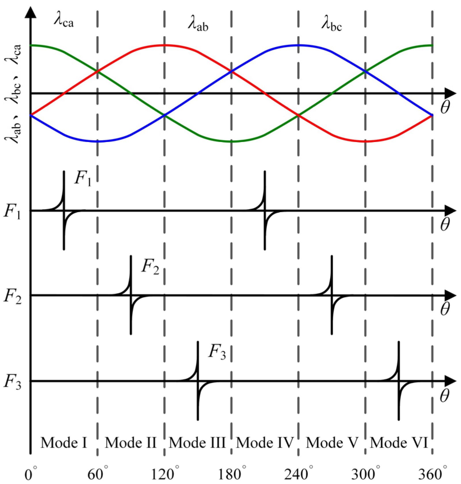
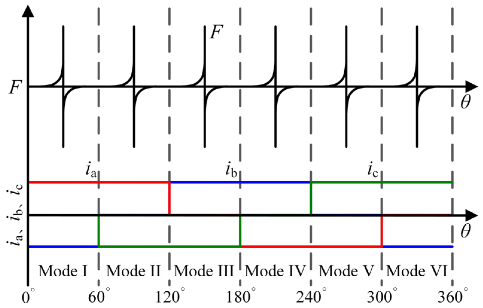
3.1. Construction and Analysis of Flux-Linkage Function

In the BLDCM, the permanent magnet (PM) flux linkage is generated by the PM, and its phase lags behind the back EMF by 90 electrical degrees. The line-to-line back EMF is numerically equal to the change rate of the line-to-line PM flux linkage with time. The line-to-line back EMF as
e i j = d λ i j d t
where eij, λij are called the line-to-line back EMF and the line-to-line PM flux linkage.
It can be seen from the formula that the line-to-line PM flux linkage of a BLDCM is numerically equal to the integral of the motor line-to-line back EMF. The line-to-line PM flux linkage with the rotor position waveform is shown in Figure 3. It can be seen from the figure that the amplitude of line-to-line PM flux linkage of the BLDCM is equal, and the phase difference of line-to-line PM flux linkage is 120 electrical degrees. Moreover, the line-to-line PM flux linkage zero crossing point is 30 electrical degrees ahead of the next commutation point.
From Formulas (1) and (2), it can obtain that the motor line-to-line voltage equation, including the line-to-line PM flux linkage as
{ u a u b = R ( i a i b )   +   L d ( i a i b ) d t + d λ ab d t u b u c = R ( i b i c )   +   L d ( i b i c ) d t + d λ bc d t u c u a = R ( i c i a )   +   L d ( i c i a ) d t + d λ ca d t
In the formula, the last item in each line is the derivative of the line-to-line PM flux linkage of the BLDCM, which is numerically equal to the line-to-line back EMF. Its amplitude is affected by the motor speed. However, the motor speed does not affect the line-to-line PM flux linkage. So this method uses the flux linkage as the basis for commutation. Generally, the neutral point of the BLDCM driven by FSTPI is not directly led out. So the line-to-line PM flux linkage can be obtained by calculating line-to-line voltage, three-phase current, and motor parameters. According to Formula (3), the line-to-line PM flux linkage as
{ λ ab = 0 t ( u a u b ) R ( i a i b ) L d ( i a i b ) d t d t λ bc = 0 t ( u b u c ) R ( i b i c ) L d ( i b i c ) d t d t λ ca = 0 t ( u c u a ) R ( i c i a ) L d ( i c i a ) d t d t
In BLDCM, the line-to-line PM flux linkage is numerically equal to the product of the motor back EMF coefficient and the flux linkage waveform function, namely
λ i j = k e · f i j
where ke is the back EMF coefficient; fij is the line-to-line PM flux linkage form function that is a function of rotor position.
In [15], to eliminate the effect of the back EMF coefficient on the function, the proposed method in that paper defines the functions F1, F2, and F3 as the ratio of the line-to-line PM flux linkage turns to estimate the rotor-commutation point. The functions F1, F2, and F3 as
{ F 1 = λ bc / λ ab F 2 = λ ab / λ ca F 3 = λ ca / λ bc
By introducing Equation (4) into Equation (6), the expressions of functions F1, F2, and F3 can be obtained as
{ F 1 = 0 t ( u b u c ) R ( i b i c ) L d ( i b i c ) d t d t 0 t ( u a u b ) R ( i a i b ) L d ( i a i b ) d t d t F 2 = 0 t ( u a u b ) R ( i a i b ) L d ( i a i b ) d t d t 0 t ( u c u a ) R ( i c i a ) L d ( i c i a ) d t d t F 3 = 0 t ( u c u a ) R ( i c i a ) L d ( i c i a ) d t d t 0 t ( u b u c ) R ( i b i c ) L d ( i b i c ) d t d t
Figure 4 shows the relationship between the functions F1, F2, F3, and the commutation sign. As can be seen from Figure 4, the function F1, F2, F3 has the following characteristics:
(1)
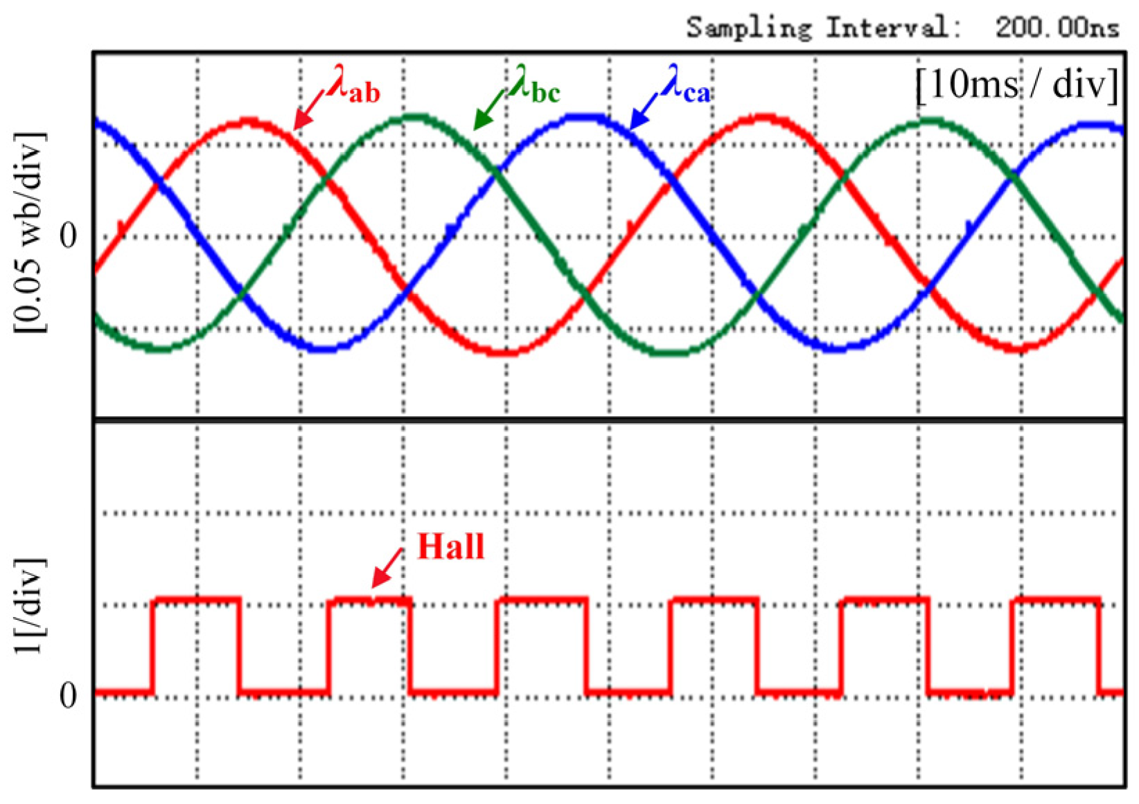
The jumping of the functions F1, F2, and F3 from positive infinity to negative infinity is only two in each electrical cycle and coincides with the commutation time after a delay of 30 electrical degrees.
(2)
In an operating mode, the function curve is similar to a hyperbola, and its functional characteristics are theoretically independent of the motor speed. Therefore, the shape of the function is the same in the entire motor speed range.
(3)
At the beginning of each operating mode, the value of the function changes slowly. When λ approaches zero, the value of the function changes quickly, and the extremum of the function jumps.

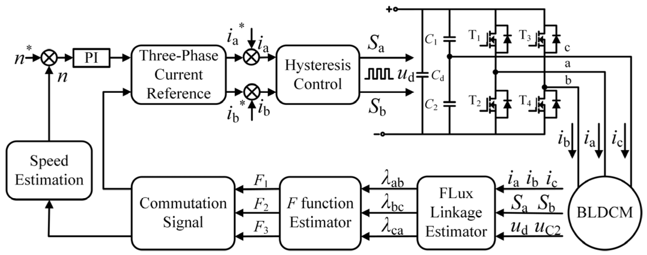
3.2. Position Sensorless Control Strategy Based on Flux-Linkage Function

For the current distortion caused by the nonconducting phase back EMF in the BLDCM driven by the FSTPI system, this proposed method uses a method of current control with separate hysteresis loop control for a-phases and b-phases. The three-phase current relationship in a BLDCM as
i a + i b + i c = 0
Since there are only two bridge arms in the FSTPI, this method achieves indirect control of the c-phase current by making the a-phase and b-phase currents the reference currents through hysteresis loop current control. Unlike the traditional BLDCM driven by FSTPI operation mode, the inverter is three-phase conduction in each operation mode during the operation of the BLDCM in this paper, and there is no floating phase. In any operating mode, the power transistor of the a-phase and b-phase bridge arms are always operating, and when the current ia is less than the reference current, the power transistor T1 is on, and the current ia increases. Conversely, the power transistor T2 conducts, and the current ia decreases. When the current ib is less than the reference current, the power transistor T3 conducts, and the current ib increases. Conversely, power transistor T4 conducts, and current ib decreases. In this current control method, the controller can calculate the terminal voltage based on the switching signal, the bus voltage, and the capacitor voltage. For example, the equivalent circuit diagram of power transistor T1 and T4 conduction is shown in Figure 5.
According to the opening and closing of the power transistor, we know that the terminal voltage of the a-phase and b-phase are DC bus voltage when they connect to the positive terminal of the DC bus. The terminal voltages of the a-phase and b-phase are zero when they connect to the negative terminal of the DC bus. The c-phase always connects to the middle point of the two series capacitors, and its terminal voltage is always the voltage at both ends of capacitor C2. Therefore, the controller can obtain the terminal voltage from the switching signal, the bus voltage, and the capacitor voltage as
{ u a = S a ( t ) · u d u b = S b ( t ) · u d u c = u C 2
where, ud is the DC bus voltage, uC2 is the voltage on capacitor C2, Sa(t), Sb(t), Sc(t) represent the state of the inverter’s three-phase bridge arm power transistor, Sk(t) = 1 (k = a,b,c) represents the upper bridge arm power transistor open, Sk(t) = 0 (k = a,b,c) represents the lower bridge arm power transistor open.
The conventional BLDCM driven by FSTPI is in modes I, III, V, and VI, with two phases on and the third phase suspended. In this case, the terminal voltage of the suspended phase varies with the terminal voltage of the two conduction phases and the back EMF of the disconnection. From Equation (9), it can be seen that in this method, the BLDCM driven by FSTPI works in each mode without suspended phase windings, and the controller only needs to measure the DC bus voltage and the voltage across capacitor C2 to calculate the terminal voltage of each phase winding based on the switching state of the power transistor and then obtain the function F1, F2, F3. This approach simplifies the terminal voltage detection circuit design and also avoids the measurement errors caused by the terminal voltage detection circuit.
From the above analysis, we know that the functions F1, F2, and F3 change slowly at the beginning of each operating mode and change quickly as λ approaches zero. This feature is very beneficial for the detection of commutation points. Since the function has two extremum jump moments in each electrical cycle of the motor, each function can provide two commutation signals in one electrical cycle. Since the BLDCM needs six commutation signals during operation, the controller can use the F1 function, F2 function, and F3 function to detect the extremum jump moment in different operating modes. In turn, the controller delays the extremum jump moment by 30 electrical degrees to obtain the next commutation point. According to the different commutation points required in each operating mode, the corresponding flux-linkage functions for each operating mode of the BLDCM driven by FSTPI can be obtained, as shown in Table 2.
According to the flux-linkage function corresponding to each operating mode in Table 2, the correspondence between each operating mode and the flux-linkage function and the reference current can be obtained, as shown in Figure 6.
Based on the above analysis, the proposed position sensorless control system for BLDCM is driven by FSTPI based on the flux-linkage function in Figure 7, where ia* and ib* is the a-phase expected current and b-phase expected current.
From Equation (7), it is necessary to integrate the voltage and current to obtain the magnetic chain. In order to prevent the integration drift phenomenon, low-pass filters are usually used instead of integrators in practical applications. The flux linkage can be expressed as
λ i j = 1 s + ω c · d λ i j d t
where ωc is the cut-off frequency.
The phase error between the flux linkage calculated by the low-pass filter and the actual flux linkage is
Δ θ = π 2 arctan ω s ω c
where ωs is the angular frequency.
In Figure 7, the controller obtains the reference current for each operating mode of the BLDCM driven by FSTPI according to the motor commutation signal and Table 2. The controller regulates the motor speed and current by controlling the a-phase and b-phase currents as reference currents through a hysteresis loop control. In each operating mode, the controller obtains the motor terminal voltage based on the collected DC bus voltage, capacitor voltage, and the switching signals of the upper and lower bridge arm power transistors in a-phase and b-phase provided by the hysteresis controller and calculates the flux-linkage function from the line to line voltage and the three-phase current. Then the controller selects different flux-linkage functions as the basis for commutation according to the different operating modes of the FSTPI and obtains six commutation points of the motor by delaying the extremum jump moment of the flux-linkage function by 30 electrical degrees. Finally, the controller can implement the motor commutation control based on the estimated commutation signal.

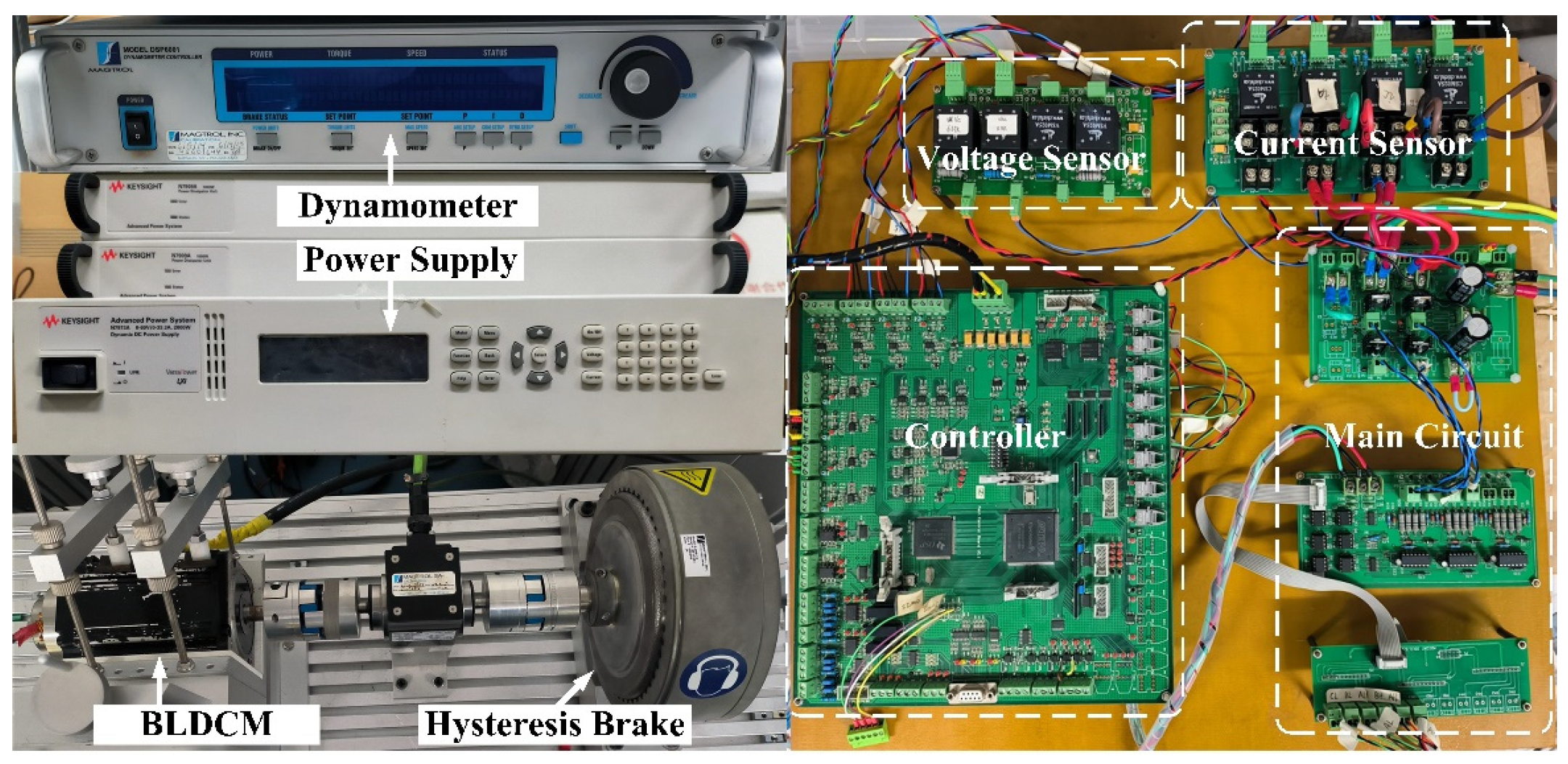
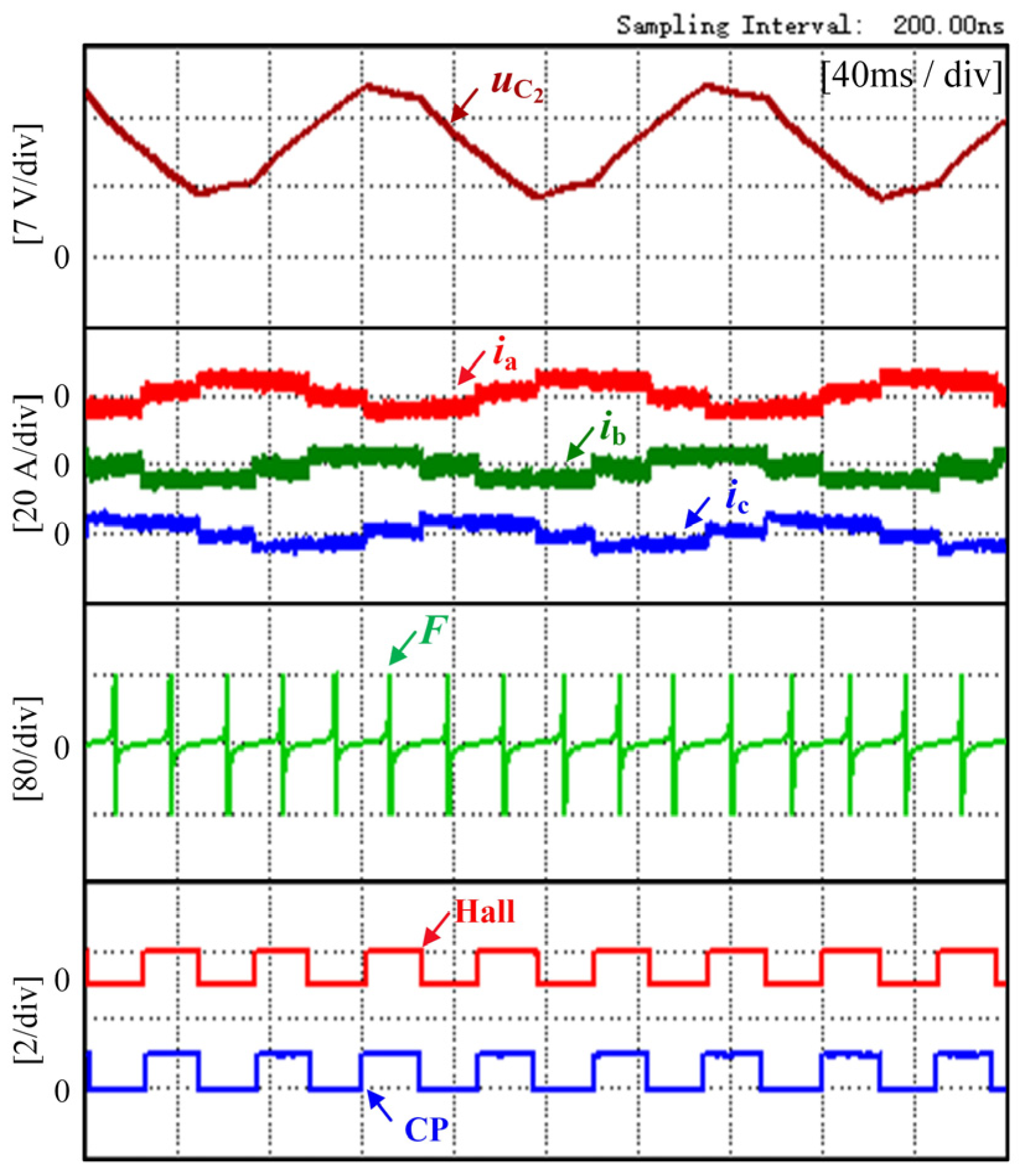
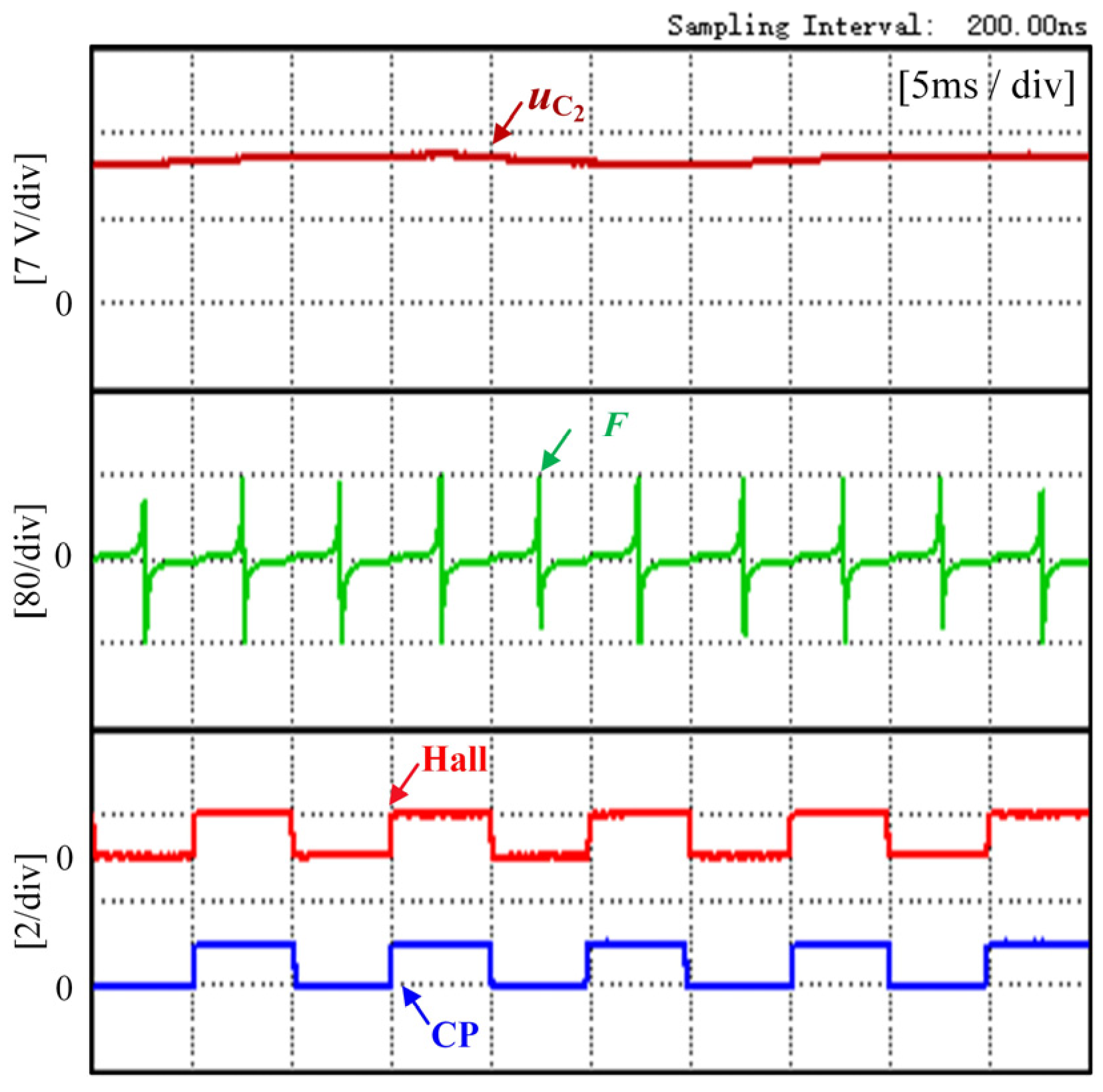
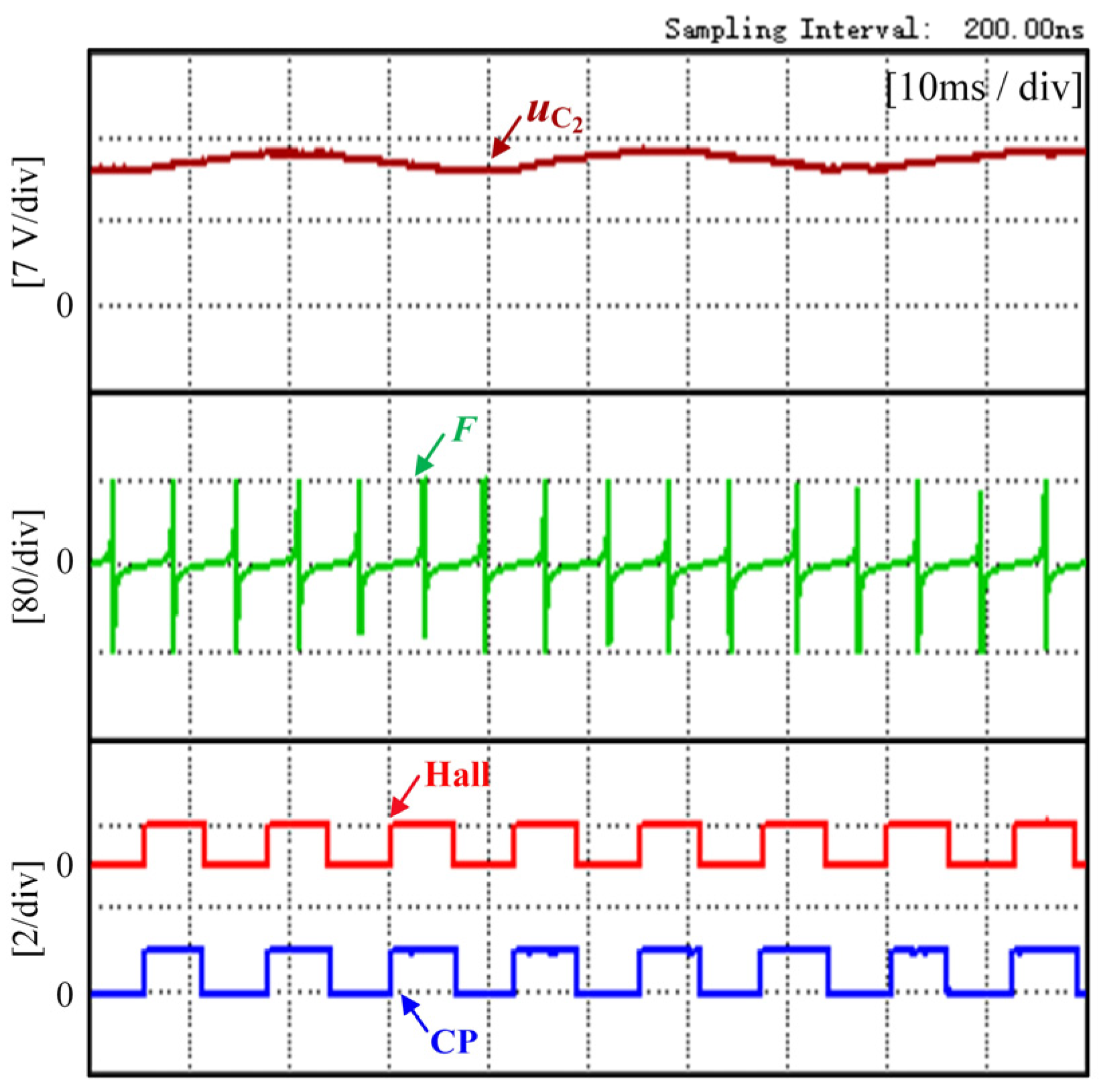
4. Experimental Results and Analysis

In order to verify the validity of the control strategy proposed and the correctness of the theoretical analysis in this paper, we built the experiment platform of BLDCM driven by FSTPI, as shown in Figure 8.
A DSP (TMS320F28335) from TI and an FPGA (EP1C6Q240C8) from ALTER built the test environment for the motor control method proposed in this paper. The MAGTROL motor test system provides the load, the Keysight N7973A provides the DC power supply of the FSTPI, and an eight-channel Yokogawa DLM4058 digital oscilloscope records the experimental waveforms. Table 3 lists the basic parameters of the experimental motor.
In order to verify the correctness of the theoretical analysis in this paper, the experimental use of the calculation method proposed in this paper obtains the line-to-line PM flux linkage. The experimental waveform of the line-to-line PM flux linkage and the Hall signal at the experimental motor at 300 r/min speed is shown in Figure 9.
Figure 9, from top to bottom, shows the line-to-line PM flux linkage and the Hall signal. Each edge of the Hall signal represents a commutation point detected by the Hall sensor. From the experimental waveform diagram, we can see that the waveform of the line-to-line PM flux linkage is consistent with the theoretical analysis, its zero crossing point at the middle moment of the two commutation signals, and its delay of 30 electrical degrees can correspond exactly to the commutation signal.
In the experiments, the method proposed in this paper is used to position sensorless control for BLDCM driven by FSTPI. The accuracy of the position estimation of the method is verified by comparing the actual Hall signal with the commutation signal CP estimated with the method. When the motor operates in mode I, mode III, mode V, and mode VI, the line-to-line voltage between the two conducting phases is approximately half of the bus voltage. This results in a bus voltage utilization of only 50% for BLDCM driven by FSTPI and affects the operating speed range and torque range of the BLDCM output.
Figure 10 shows the experimental waveform at 300 r/min speed and 1 N·m torque. Figure 11 shows the experimental waveform at 300 r/min speed and 0.5 N·m torque. The voltage across capacitor C2, the three-phase current, the flux-linkage function, the Hall signal, and the commutation signal CP are shown from top to bottom in Figure 10. In the experiment, the controller gets the commutation point by detecting when the flux-linkage function changes from positive to negative polarity and delaying 30 electrical degrees.
From the experimental results, the three-phase conduction current control method used in this paper can effectively control the three-phase current of BLDCM driven by FSTPI. The controller makes the c-phase current zero by controlling the power transistors of the a-phase and b-phase when the c-phase is the nonconducting phase. The value of the flux-linkage function is usually small but increases significantly near the extreme point. Since this experiment limits the output of D/A to ±80, it can be seen from the experimental waveform that the flux linkage function jumps from +80 to −80 near the extreme point, and its jump is very obvious, and there is no need to set a threshold. It is consistent with the theoretical analysis and is very beneficial for detecting the commutation point. The waveform of the flux-linkage function does not change under different speeds and loads, and the method can accurately detect the commutation signal CP, and thus, realizing an accurate commutation of BLDCM driven by FSTPI. In the process of the position sensorless control, the fluctuation of speed, sampling error, and the change of parameter value with temperature will affect the position detection accuracy. In this experiment, the motor commutation error is about 2 electrical degrees under 300 r/min speed.
The capacitor voltage of the BLDCM driven by FSTPI will fluctuate more seriously at low speeds and heavy loads, which is very unfavorable to motor operation. To make the control performance of the motor better, the experimental waveforms at lower speeds in this experiment are shown in Figure 12 and Figure 13. Figure 12 shows the experimental waveform at 200 r/min speed and 0.8 N·m torque. Figure 13 shows the experimental waveform at 100 r/min speed and 0.5 N·m torque.
The difference between the maximum value and the minimum value of the capacitor voltage fluctuation in Figure 12 is about 8 V, and the difference between the maximum value and the minimum value of the capacitor voltage fluctuation in Figure 13 is about 11 V. The capacitor voltage fluctuation under these two operating conditions has been considerable.
As seen from Figure 12 and Figure 13, even under large fluctuations in capacitor voltage, the precise commutation of the BLDCM can still be achieved using the method proposed in this paper. The motor maximum commutation error is about 4 electrical degrees at these two speeds.
The utilization rate of the bus voltage of BLDCM driven by FSTPI is only 50%, and the back EMF voltage is close to the capacitor voltage of the capacitor bridge arm at high speed (close to the rated speed of the motor). The motor is operated under high speed and light load test conditions in this experiment. Figure 14 shows the experimental waveform at 500 r/min speed and 0.1 N·m torque, and Figure 15 shows the experimental waveform at 400 r/min speed and 0.5 N·m torque. From the waveforms, it can be seen that the commutation accuracy of the motor can still be guaranteed even at higher speeds. The motor maximum commutation error is about 2 electrical degrees at these two speeds.
In order to detect the commutation accuracy of the proposed method, the average commutation error and the extreme value of the flux-linkage function waveform at each speed in the experiment are counted, as shown in Table 4.
It can be seen from the table that the commutation accuracy of this method increases with the motor speed from low to high, and the maximum commutation error is only 4 electrical degrees. This is because the flux linkage is numerically equal to the integral of the back EMF to the time. In the actual detection process, the flux linkage is obtained by sampling the voltage and current. When the speed is high, the equivalent back EMF obtained through calculation is large, and the signal-to-noise ratio is high. At this time, the error of using this method is also small. In addition, it can be seen from the table that the extreme value of the flux-linkage function is large at each speed, and the extreme value jump is evident at each speed.
The above experimental results show that since this method uses a three-phase current control method for BLDCM driven by FSTPI, the terminal voltage can be obtained by calculation. This approach avoids the errors caused by the hardware sampling circuit and has a high estimation accuracy. In addition, the waveform shape of the flux-linkage function is the same at all speeds. The controller can obtain the ideal flux-linkage function waveform and the commutation signal CP to precisely match the Hall signal.

5. Conclusions

The flux-linkage function is introduced to estimate the commutation point based on the three-phase current control of the motor, thus enabling position sensorless control for BLDCM driven by FSTPI. The proposed strategy has the following advantages.
(1)
Six phase commutation points are obtained using the speed-independent PM flux linkage without interpolation, and good commutation accuracy is guaranteed at all speeds except for very low speeds.
(2)
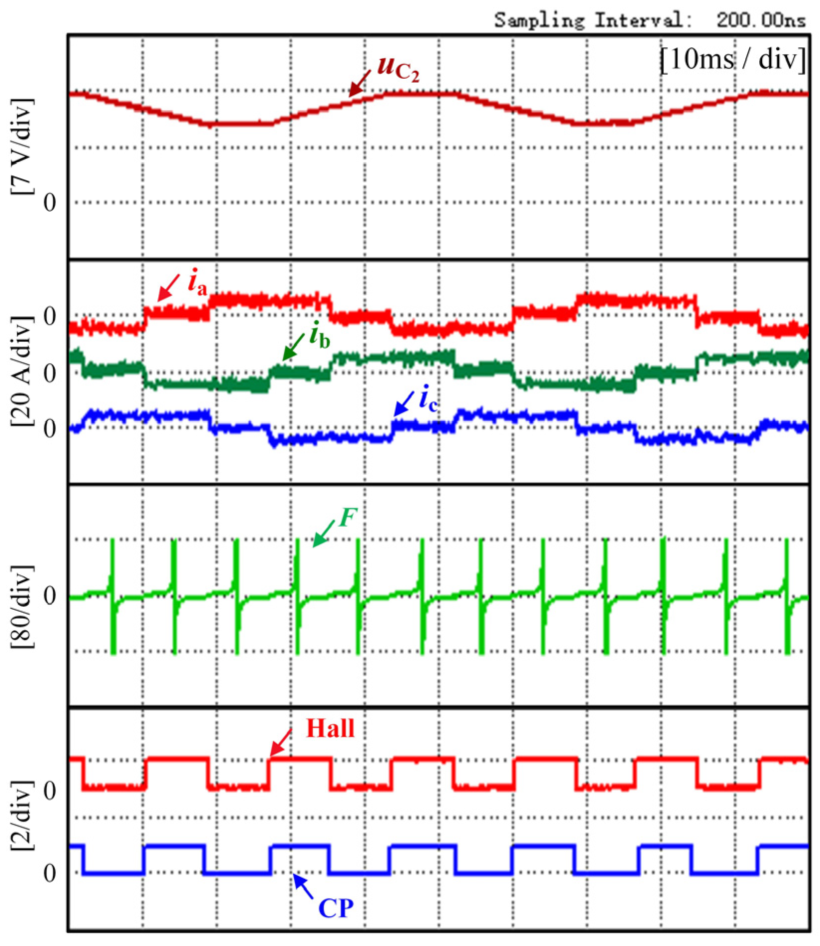
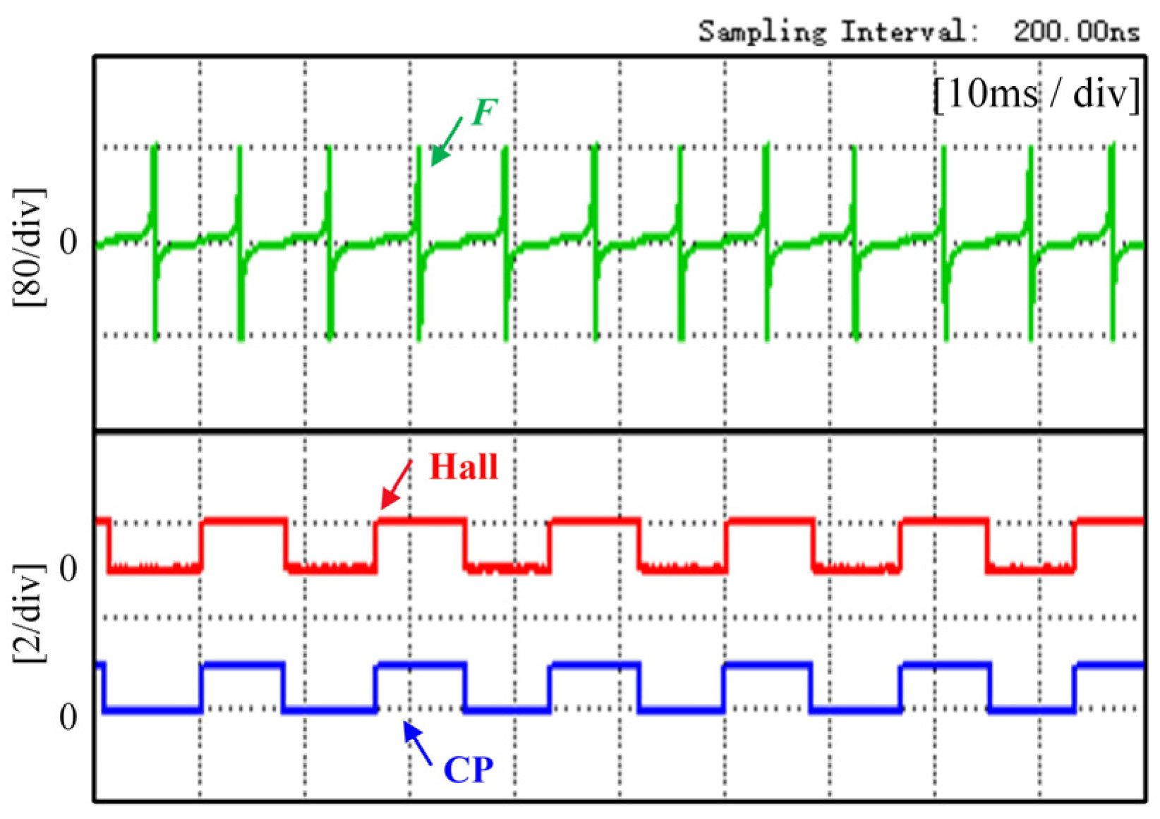
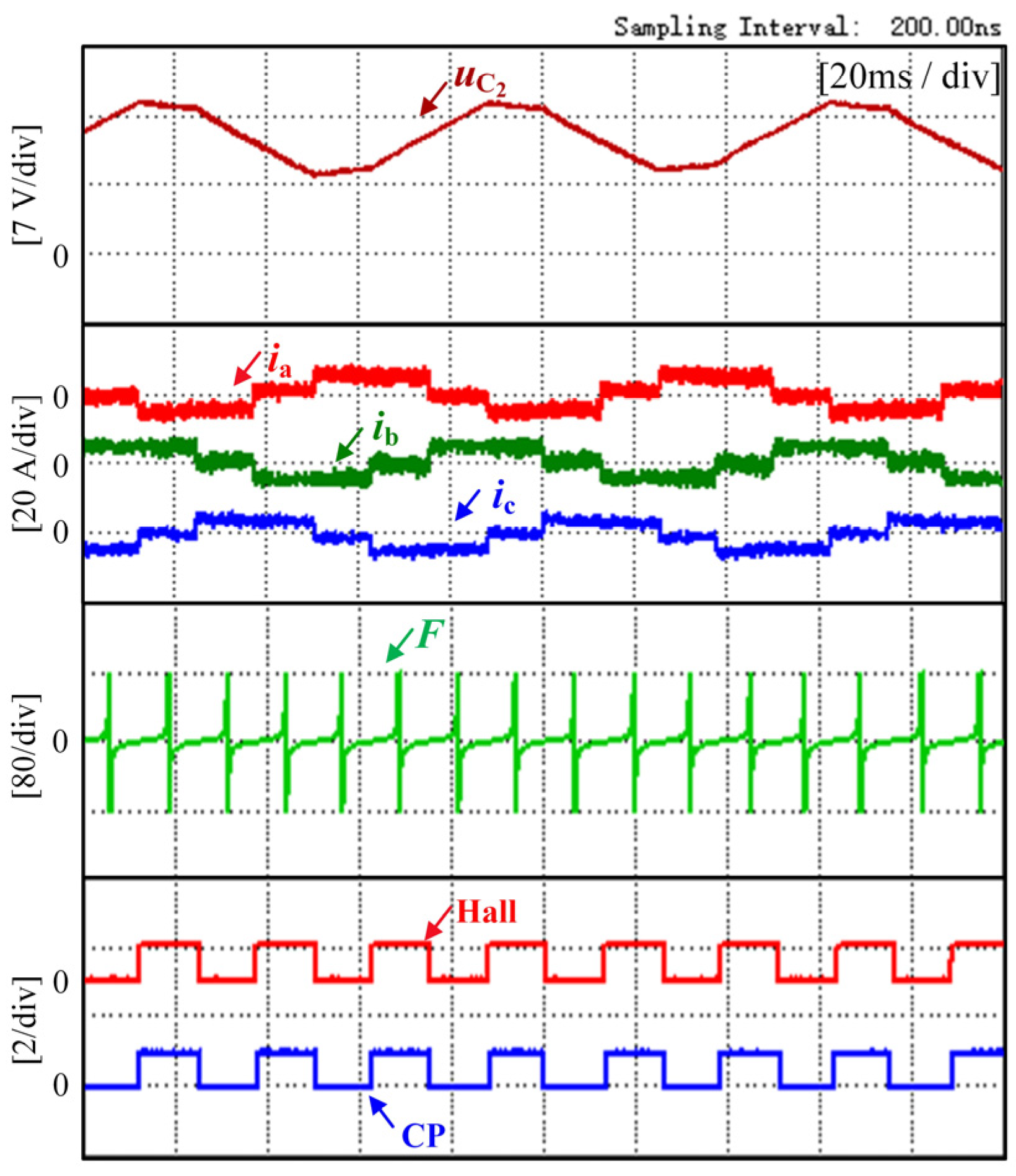
There is no need to obtain the commutation point by setting the threshold value, which can reduce the commutation error caused by unreasonable threshold setting. And the flux-linkage function increases significantly near the extremum point, which increases the reliability of commutation point detection.
(3)
The three-phase current control method suppresses the nonconducting phase current distortion. On this basis, the terminal voltage required to calculate the flux-linkage function by the switching signal avoids the error caused by hardware sampling.
In addition, the proposed sensorless control method avoids the use of position sensors without increasing the cost, improves the operation reliability of BLDCM driven by FSTPI, and reduces the size of the motor. This has important implications for the application of FSTPI and the application of BLDCM driven by FSTPI reconfigured after the failure of conventional SSTPI in various environments. Future work in this study could replace the hysteresis loop controller with a PI controller from the perspective of current control and replace the switching signal with a duty cycle to calculate the terminal voltage. This will improve the utilization of the system control frequency, thus reducing the fluctuation of the current, and will also not affect the detection of the position.

Author Contributions

Data curation, X.L.; formal analysis, X.L. and G.J.; funding acquisition, X.L; investigation, Q.L. and W.C.; methodology, W.C.; project administration, Z.Z. and G.Z.; resources, Z.Z.; validation, G.J. and Q.L.; writing—original draft, G.J.; writing—review and editing, X.L. All authors have read and agreed to the published version of the manuscript.

Funding

This research was supported by “The National Natural Science Foundation of China, grant numbers 52077155 and 51807141”, “The Zhejiang Provincial Basic Public Welfare Research Projects under grant numbers LGG22E070011”, “The Key Program of Tianjin Natural Science Foundation, grant number 20JCZDJC00020”.

Institutional Review Board Statement

Not applicable.

Informed Consent Statement

Not applicable.

Data Availability Statement

Not applicable.

Conflicts of Interest

Qiang Li is an employee of Weichai Power Co., Ltd., Shandong 261061, China. The paper reflects the views of the scientists and not the company.

References

  1. Chen, S.; Liu, G.; Zhu, L. Sensorless startup strategy for a 315- kW high-speed brushless DC motor with small inductance and nonideal back EMF. IEEE Trans. Ind. Electron. 2019, 66, 1703–1714. [Google Scholar] [CrossRef]
  2. Li, Y.; Song, X.; Zhou, X.; Huang, Z.; Zheng, S. A sensorless commutation error correction method for high-Speed BLDC motors based on phase current integrations. IEEE Trans. Ind. Inform. 2020, 16, 328–338. [Google Scholar] [CrossRef]
  3. Zhao, D.; Wang, X.; Tan, B.; Xu, L.; Yuan, C. Fast commutation error compensation for BLDC motors based on virtual neutral voltage. IEEE Trans. Power Electron. 2021, 36, 1259–1263. [Google Scholar] [CrossRef]
  4. Tan, B.; Wang, X.; Zhao, D.; Shen, K.; Zhao, J. A lag angle compensation strategy of phase current for high-speed BLDC motors. IEEE Access 2018, 7, 9566–9574. [Google Scholar] [CrossRef]
  5. Song, X.; Han, B.; Wang, K. Sensorless drive of high-speed BLDC motors based on virtual third-harmonic back EMF and high-precision compensation. IEEE Trans. Power Electron. 2019, 34, 8787–8796. [Google Scholar] [CrossRef]
  6. Shen, J.X.; Iwasaki, S. Sensorless control of ultra high-speed PM brushless motor using PLL and third harmonic back EMF. IEEE Trans. Ind. Electron. 2006, 53, 421–428. [Google Scholar] [CrossRef]
  7. Lai, Y.-S.; Lin, Y.-K. A unified approach to zero-crossing point detection of back EMF for brushless DC motor drives without current and hall sensors. IEEE Trans. Power Electron. 2011, 26, 1704–1713. [Google Scholar] [CrossRef]
  8. Cui, C.; Liu, G.; Song, X. Sensorless drive for high-speed brushless DC motor based on the virtual neutral voltage. IEEE Trans. Power Electron. 2015, 30, 3275–3285. [Google Scholar] [CrossRef]
  9. Liu, G.; Cui, C.; Wang, K.; Han, B.; Zheng, S. Sensorless control for high-speed brushless DC motor based on the line-to-line back EMF. IEEE Trans. Power Electron. 2016, 31, 4669–4683. [Google Scholar] [CrossRef]
  10. Li, H.; Zheng, S.; Ren, H. Self-correction of commutation point for high-speed sensorless BLDC motor with low inductance and nonideal back EMF. IEEE Trans. Power Electron. 2017, 32, 642–651. [Google Scholar] [CrossRef]
  11. Ying, L.; Ertugrul, N. A novel robust DSP-based indirect rotor position estimation for permanent magnet AC motors without rotor saliency. IEEE Trans. Power Electron. 2003, 18, 539–546. [Google Scholar] [CrossRef]
  12. Gao, J.; Hu, Y. Direct self-control for BLDC motor drives based on three-dimensional coordinate system. IEEE Trans. Ind. Electron. 2010, 57, 2836–2844. [Google Scholar]
  13. Haines, G.; Ertugrul, N. Wide speed range sensorless operation of brushless permanent-magnet motor using flux linkage increment. IEEE Trans. Ind. Electron. 2016, 63, 4052–4060. [Google Scholar] [CrossRef]
  14. Chen, S.; Liu, G.; Zhu, L. Sensorless control strategy of a 315 kW high-speed BLDC motor based on a speed-independent flux linkage function. IEEE Trans. Ind. Electron. 2017, 64, 8607–8617. [Google Scholar] [CrossRef]
  15. Chen, W.; Liu, Z.B.; Shi, T.N.; Xia, C.L. A position sensorless control strategy for the BLDCM based on a flux-linkage function. IEEE Trans. Ind. Electron. 2019, 66, 2570–2579. [Google Scholar] [CrossRef]
  16. Gambetta, D.; Ahfock, A. New sensorless commutation technique for brushless DC motors. IET Electr. Power Appl. 2009, 3, 40–49. [Google Scholar] [CrossRef] [Green Version]
  17. Champa, P.; Somsiri, P.; Wipasuramonton, P.; Nakmahachalasint, P. Initial rotor position estimation for sensorless brushless DC drives. IEEE Trans. Ind. Appl. 2009, 45, 1318–1324. [Google Scholar] [CrossRef]
  18. Chen, W.; Dong, S.; Li, X. Initial rotor position detection for brushless DC motors based on coupling injection of high-frequency signal. IEEE Access 2019, 7, 133433–133441. [Google Scholar] [CrossRef]
  19. Wu, X.; Zhu, Z.Q.; Wu, Z. A novel rotor initial position detection method utilizing DC-link voltage sensor. IEEE Trans. Ind. Appl. 2020, 56, 6486–6495. [Google Scholar] [CrossRef]
  20. Zhou, D.; Zhao, J.; Liu, Y. Predictive torque control scheme for three-phase four-switch inverter-fed induction motor drives with DC-link voltages offset suppression. IEEE Trans. Power Electron. 2015, 30, 3309–3318. [Google Scholar] [CrossRef]
  21. Zhou, D.; Li, X.; Tang, Y. Multiple-vector model predictive power control of three-phase four-switch rectifiers with capacitor voltage balancing. IEEE Trans. Power Electron. 2018, 33, 5824–5835. [Google Scholar] [CrossRef]
  22. Lin, C.; Hung, C.; Liu, C. Position sensorless control for four-switch three-phase brushless DC motor drives. IEEE Trans. Power Electron. 2008, 23, 438–444. [Google Scholar] [CrossRef]
  23. Niasar, A.H.; Vahedi, A.; Moghbelli, H. A novel position sensorless control of a four-switch, brushless DC motor drive without phase shifter. IEEE Trans. Power Electron. 2008, 23, 3079–3087. [Google Scholar] [CrossRef]
  24. Niasar, A.H.; Vahedi, A.; Moghbelli, H. Low-cost sensorless control of four-switch, brushless DC motor drive with direct back-EMF detection. J. Zhejiang Univ. Sci. A 2009, 10, 201–208. [Google Scholar] [CrossRef]
  25. Kivanc, O.C.; Ozturk, S.B. Low-Cost Position Sensorless Speed Control of PMSM Drive Using Four-Switch Inverter. Energies 2019, 12, 741. [Google Scholar] [CrossRef] [Green Version]
  26. Ozturk, S.B.; Kivanc, O.C. Rotor Position Alignment of FSTPI Based PMSM Drive Using Low Frequency Signal Injection. Appl. Sci. 2020, 10, 7397. [Google Scholar] [CrossRef]
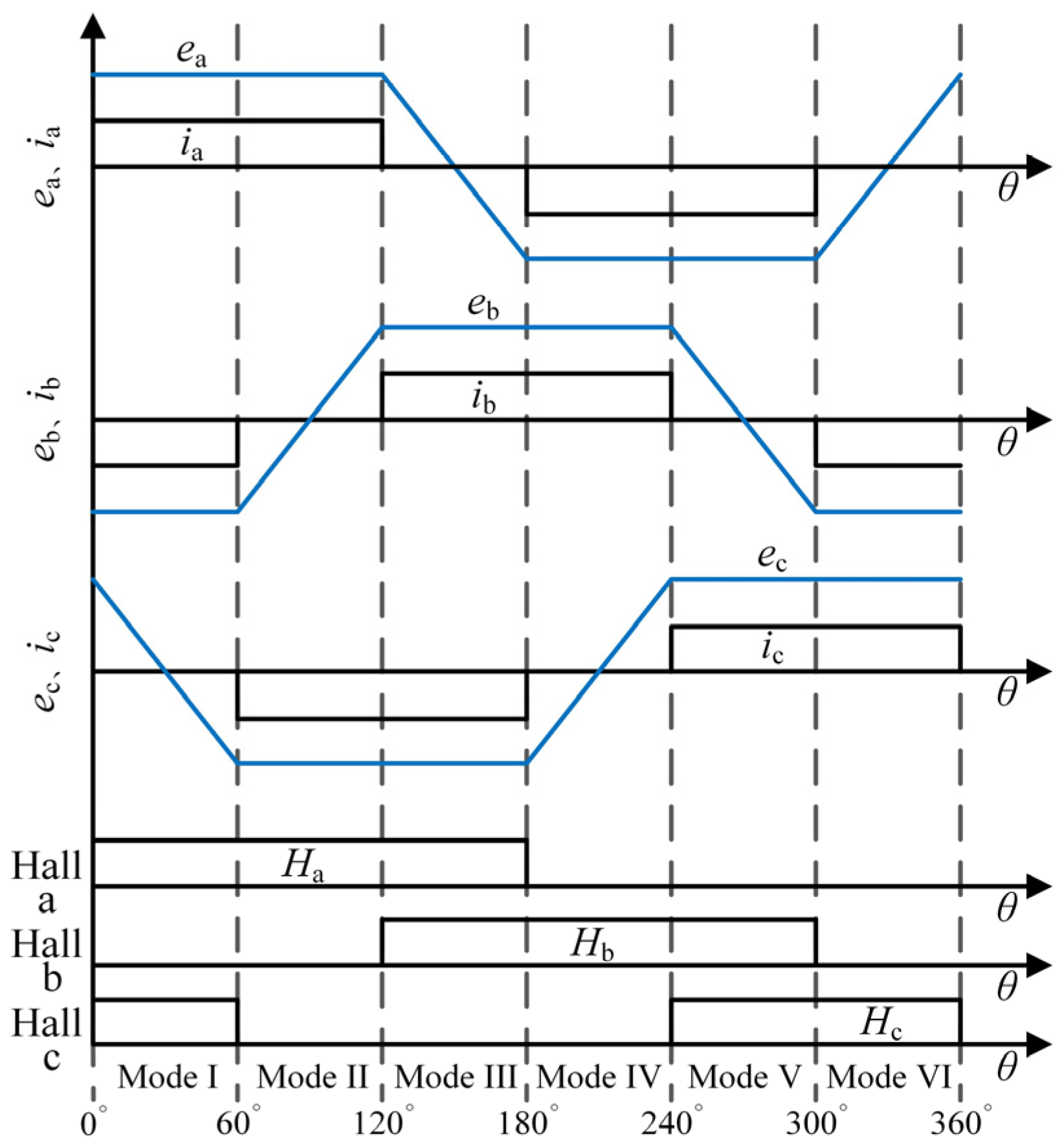
Figure 1. BLDCM is driven by FSTPI equivalent circuit.
Wevj 13 00238 g001
Figure 2. Schematic diagram of back EMF, phase current, and Hall signal of BLDCM.
Wevj 13 00238 g002
Figure 3. Line-to-line PM flux linkage with rotor position waveform.
Wevj 13 00238 g003
Figure 4. Line-to-line PM flux linkage and function F1, F2, F3 diagram.
Wevj 13 00238 g004
Figure 5. Equivalent circuit diagram under the conduction of power transistors T1 and T4.
Wevj 13 00238 g005
Figure 6. Flux-linkage function and reference current waveform.
Wevj 13 00238 g006
Figure 7. The position sensorless control system for BLDCM driven by FSTPI based on flux-linkage function.
Wevj 13 00238 g007
Figure 8. Experimental system.
Wevj 13 00238 g008
Figure 9. Line-to-line PM flux linkage and Hall signal waveform at 300 r/min.
Wevj 13 00238 g009
Figure 10. Experimental waveform under the condition of 300 r/min speed and 1 N·m torque.
Wevj 13 00238 g010
Figure 11. Experimental waveform under the condition of 300 r/min speed and 0.5 N·m torque.
Wevj 13 00238 g011
Figure 12. Experimental waveform under the condition of 200 r/min speed and 1 N·m torque.
Wevj 13 00238 g012
Figure 13. Experimental waveform under the condition of 100 r/min speed and 0.8 N·m torque.
Wevj 13 00238 g013
Figure 14. Experimental waveform under the condition of 500 r/min speed and 0.1 N·m torque.
Wevj 13 00238 g014
Figure 15. Experimental waveform under the condition of 400 r/min speed and 0.5 N·m torque.
Wevj 13 00238 g015
Table 1. The operating mode of BLDCM driven by FSTPI.
Operating ModeOperating PhaseExpected CurrentOperating Devices
I+a, −bia = I*, ib = −I*T1, T4
II+a, −cia = I*, ic = −I*T1
III+b, −cib = I*, ic = −I*T3
IV+b, −aib = I*, ia = −I*T2, T3
V+c, −aic = I*, ia = −I*T2
VI+c, −bic = I*, ib = −I*T4
Table 2. Relationship between each operating mode and flux-linkage function.
Operating ModeExpected CurrentFlux-Linkage Function
Iia = I*, ib = −I*F1
IIia = I*, ic = −I*F2
IIIib = I*, ic = −I*F3
IVib = I*, ia = −I*F1
Vic = I*, ia = −I*F2
VIic = I*, ib = −I*F3
Table 3. Experimental motor parameters.
ParameterValueUnit
Rated voltage UN24V
Rated current IN14A
Rated torque TN3.2N·m
Rated speed nN600r/min
Phase resistance R0.2415Ω
Phase inductance L0.387mH
Phase Back EMF coefficient Ke0.128V/(rad/s)
Poles pairs p4
Table 4. Commutation error of the proposed method.
Speed100 rmp200 rmp300 rmp400 rmp500 rmp
Commutation error
Flux-linkage function extremum8080807779
Publisher’s Note: MDPI stays neutral with regard to jurisdictional claims in published maps and institutional affiliations.

