Article

Wide Frequency PWM Rectifier Control System Based on Improved Deadbeat Direct Power Control

1
School of Electrical Engineering, Tiangong University, Tianjin 300387, China
2
WEICHAI Power Co., Ltd., Weifang 261061, China
3
Advanced Electrical Equipment Innovation Center, Zhejiang University, Hangzhou 311107, China
*
Author to whom correspondence should be addressed.
World Electr. Veh. J. 2022, 13(12), 230; https://doi.org/10.3390/wevj13120230
Submission received: 2 November 2022 / Revised: 22 November 2022 / Accepted: 28 November 2022 / Published: 2 December 2022
(This article belongs to the Special Issue Electrical Machines Design and Control in Electric Vehicles)

Abstract

:
The precision of deadbeat direct power control depends on the parameters of the system model. In wide frequency applications, such as multi- electric aircraft and electric vehicles, variations in frequency and resistive parameters will affect the control effect. The AC side voltage frequency of the generator rectifier varies widely, which will lead to a steady-state reactive power error in the deadbeat direct power control. In addition, the large temperature variation range during the operation of the multi-electric aircraft and electric vehicles leads to large changes in the filter inductance and line resistance of the AC side, and the model parameters do not match the actual parameters, which will further deteriorate the control accuracy. In this paper, a PWM rectifier control method is proposed for the occasions when the frequency and temperature change are in a wide range. Using repetitive control and power compensation, it solves the problems of steady-state reactive power error and control accuracy degradation caused by the mismatch of model parameters under severe operating conditions. The control method can precisely adjust the output DC voltage of PWM rectifier, and it also can maintain unity power factor and reduce the total harmonic distortion rate of the input current. The effectiveness of the proposed control method is verified by the experimental results.

1. Introduction

Electrically powered vehicles, such as More Electric Aircraft (MEA) and electric vehicles (EV), consume less energy, have fewer emissions and maintenance, and cost less than conventional fossil-fueled vehicles. Combining electric drives with power electronic control strategies in MEAs and EVs improves overall system efficiency, reduces weight and costs, and meets reliability requirements [1,2].
In some commercial transport equipment, such as Boeing 787 and Airbus A380, the main engine generator is directly coupled to the jet engine through the gearbox, the AC voltage frequency of the aircraft is proportional to the engine speed, and the voltage frequency is between 360 Hz and 800 Hz [3]. The three-phase AC voltage is rectified by using an AC-DC converter before distributing to the aircraft DC load. Conventional aircraft use a transformer rectifier unit [4] or an autotransformer rectifier unit [5] to provide a DC side voltage with multiple pulses (12 or 18 pulses). These rectifying devices have met the requirements of the DO-160G for current harmonics but with enormous weight and volume [6]. PWM rectifiers are attracting much attention as they use fully controlled switching devices to control the AC-side current and DC-side voltage through switching choppers. Compared to autotransformer rectifiers, PWM rectifiers have a smaller size and weight and a wider control frequency. A suitable PWM control strategy can enhance the dynamic and static performance of the system, improve the stability of the DC-side voltage and reduce the total harmonic content of the AC current. Two-level, multi-level PWM rectifiers and Vienna rectifiers, for example, have power factor correction capability and can operate at a unit power factor. They also have the advantages of simple construction, a low number of semiconductor devices, and low total harmonic distortion of the input current [7,8,9]. Therefore, PWM active rectifiers have more advantages than conventional rectifiers in wideband power supplies.
Since direct power control does not require a current loop, the active power and reactive power of the system can be directly adjusted by checking the switch table to select the appropriate voltage vector. It is mostly used in motor speed control systems, active filters, etc. Direct power control require high dynamic performance of the rectifier. Due to its superior power control performance, it has been deeply studied by scholars.
Because a hysteresis comparator is used for power regulation in direct power control, the switching frequency changes, and high sampling frequency sensors are needed to obtain good control performance [10]. To solve the above problems, domestic and foreign scholars proposed a fixed frequency direct power control method. Reference [11] fixed frequency control is realized by using a PI regulator and SVPWM to direct the active and reactive power compensation, and the line voltage sensor was replaced by the virtual flux estimator. It has the characteristics of a simple algorithm, good dynamic response and constant switching frequency, especially when the supply voltage is not ideal; this scheme can reduce the total harmonic distortion. In reference [12], a control strategy combining direct power control and SVPWM was further established to compensate for voltage drop and harmonics under non-ideal conditions. Some of the literature improves the control performance of direct power control by using nonlinear controllers. In reference [13], sinusoidal input current with unit power factor can be generated using model predictive control without any current controller or modulator. The system has the characteristics of a fast dynamic response of directly controlling the input power. The literature [14] achieves a reduction in dc-side voltage bias under wide frequency conditions by using a double low-pass filter, but the problems of reactive power error and controller parameter mismatch are not investigated.
If the prediction model does not match the actual system parameters, the normal operation of the system will be affected, and the system will be unstable [15]. In order to solve the problem of parameter mismatch, scholars have proposed different solutions. In reference [15], a robust model predictive current controller with disturbance observer is proposed for three-phase voltage PWM rectifier. Luenberger observer is constructed for parameter mismatch and model uncertainty. The proposed method has fast dynamic response and good robustness. The literature [16] proposes a model predictive current control with fixed switching frequency and deadband compensation that has lower current THD compared to direct power control methods. In reference [17], robust current predictive control based on internal model disturbance observer is proposed to achieve accurate current loop control, which can achieve fast and accurate control when parameters are disturbed and there is model mismatch. This method significantly improves the robustness of the system. In reference [18], the relationship between parameter mismatch and current control effect is deduced on the basis of the discrete domain model of voltage type rectifier, and an improved model predictive control strategy for grid-connected parameter mismatch is proposed. The method is to correct the beat free control parameters in real time through on-line inductor identification. The simulation and experimental results show that the on-line inductance identification control strategy can accurately identify the inductance in static and dynamic processes, reduce the dependence of the deadbeat on the accuracy of model parameters, and improve the fault tolerance rate of the control system. According to the variation and uncertainty of input filter impedance, an adaptive model predictive control is proposed in reference [19], the proposed method can adaptively adjust the model parameters in the predictive equation and improve the stability of the model. The proposed modeling scheme of automatic adjustment does not require additional sensors while keeping the controller simple. Although the above predictive control schemes are effective, the fundamental frequency of the AC side of the rectifier is constant by default, and there is no measure to solve the error caused by frequency parameter mismatch.
American scholars proposed a deadbeat direct power control scheme combined with the variation of sampling frequency of instantaneous PLL, the proportional integral controller was used to adjust the voltage of the DC bus so that the total harmonic distortion was low and the AC side kept the unit power factor [20]. Since the expected value of the instantaneous reactive power is 0 and there is no control loop, the accumulation of reactive power error will occur under the condition of frequency and inductance resistance parameter mismatch, resulting in the steady-state error of the instantaneous reactive power, and the power factor will be affected by the steady-state error of the reactive power and thus reduced.
In this paper, the control strategy is improved to solve the problem of reactive power steady state error when the frequency changes and the model parameter mismatch is caused by the parameter changes. In the improved strategy, repeated control is added, and the error of instantaneous reactive power is repeatedly accumulated and iterated to reduce the steady-state error of reactive power. At the same time, a power compensation module is added to solve the extra instantaneous reactive power caused by the change of model parameters, which can quickly respond to the change of parameters and make the reactive power more stable than the traditional method under wide frequency conditions. The specific scheme is shown in Figure 1. The whole system is divided into five modules: rectifier module, filter module, phase locked loop module, improved repetitive control module and PI control module. This paper mainly introduces the improved repetitive control modules.
The first section describes the modeling and lead control strategy of the three-phase AC-DC converter. In Section 2, the deficiency of lead control and the improvement of repeated control method are explained. In Section 3, experimental results are presented to demonstrate the performance of the proposed control scheme.

2. PWM Rectifier Model and Traditional Deadbeat Direct Power Control Strategy

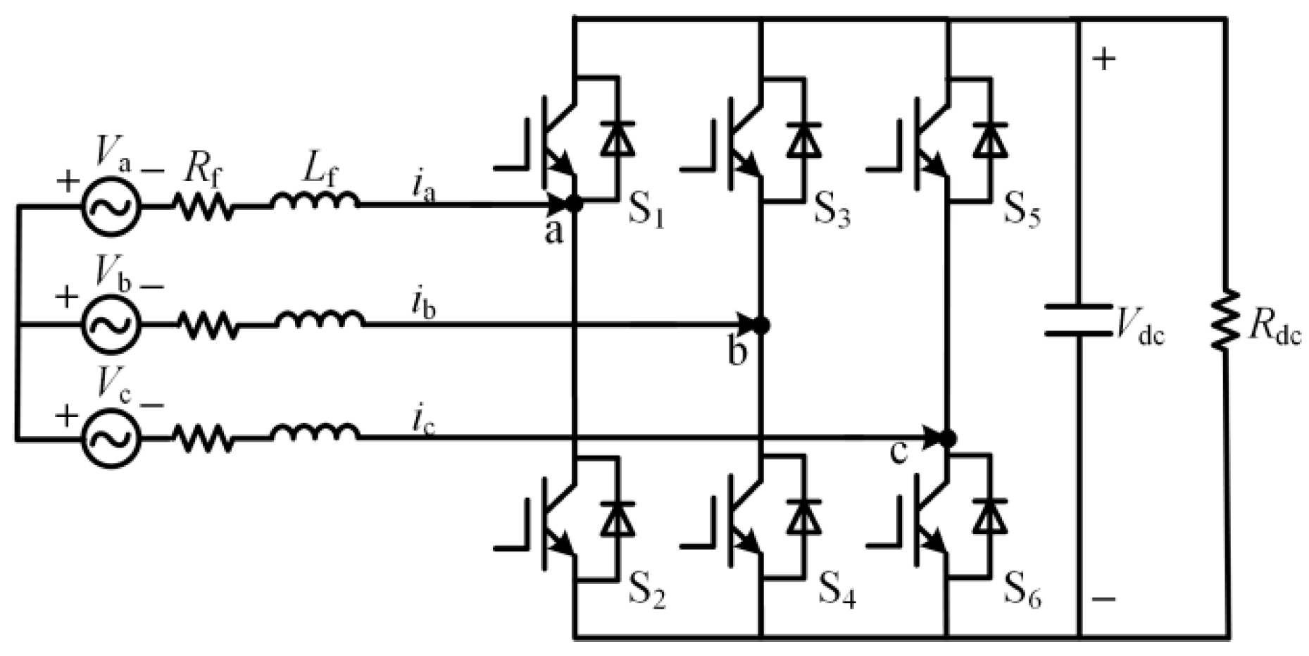
2.1. Mathematical Model of Voltage Type PWM Rectifier

The main circuit topology of three-phase voltage PWM rectifier is shown in Figure 2.
In the Figure 2, Va, Vb and Vc are three-phase symmetric AC voltages, ia, ib and ic are corresponding three-phase AC currents, S1–S6 are six way switches, Vdc is the DC side voltage of the rectifier, Lf is the filter inductor, Rf is the sum of the resistance in the filter inductor and the equivalent resistance of the switch loss, and Rdc is the load resistance.
Based on Figure 2, assuming that the three-phase voltage of the AC side of the system is balanced and sinusoidal, the mathematical model of the PWM rectifier can be expressed as [14]
{ V Ra   =   V a R f i a L f d i a d t V Rb   =   V b R f i b L f d i b d t V Rc   =   V c R f i c L f d i c d t
where VRa, VRb and VRc represent the three-phase voltage value of the voltage type PWM rectifier side. Using the method of coordinate transformation in motor control, the parameters in the above equation are transformed into the αβ two-phase stationary coordinate system by orthogonal transformation. The mathematical model of the voltage type PWM rectifier in the stationary coordinate system is identified and obtained as [21]
{ V R α   =   V α R f i α L f d i α d t V R β   =   V β R f i β L f d i β d t
PWM rectifiers are composed of controlled semiconductor devices turned on and off by a pulse signal from the controller. PWM rectifiers have a higher switching frequency than conventional rectifiers and can provide a higher sampling frequency to meet the requirements of high precision control algorithms.

2.2. Deadbeat Direct Power Control Strategy

Deadbeat direct power control is a constant switching frequency model predictive control scheme based on the principle of deadbeat control [18]. The main objective of the control scheme is to adjust the output DC bus voltage and perform power factor correction. The specific implementation scheme is as follows. Firstly, the forward Euler formula is used to discretize Equation (2)
{ V R α [ k ]   =   V α [ k ] R f i α [ k ] L f T s ( i α [ k + 1 ] i α [ k ] ) V R β [ k ]   =   V β [ k k ] R f i β [ k ] L f T s ( i β [ k + 1 ] i β [ k ] )
where iα[k + 1] and iβ[k + 1] are the components of the line current at time (k + 1)Ts in the stationary coordinate system. The instantaneous active power p and the instantaneous reactive power q at time (k + 1)Ts are expressed as
{ p [ k + 1 ]   =   1.5 ( V β [ k + 1 ] i β [ k + 1 ] + V α [ k + 1 ] i α [ k + 1 ] ) q [ k + 1 ]   =   1.5 ( V β [ k + 1 ] i α [ k + 1 ] V α [ k + 1 ] i β [ k + 1 ] )
When the two sets of equations in Equation (4) are simultaneous, iα[k + 1] and iβ[k + 1] can be expressed by instantaneous active power and instantaneous reactive power, as below
{ i α [ k + 1 ]   =   2 3 p [ k + 1 ] V α [ k + 1 ] + q [ k + 1 ] V β [ k + 1 ] V α 2 [ k + 1 ] + V β 2 [ k + 1 ] i β [ k + 1 ]   =   2 3 p [ k + 1 ] V β [ k + 1 ] q [ k + 1 ] V α [ k + 1 ] V α 2 [ k + 1 ] + V β 2 [ k + 1 ]
The current, voltage and power in the above equation are expressed in the plural form x = xα + jxβ, and the expected value of instantaneous active power p[k + 1] = pref[k + 1] is set, which is output by PI controller. In order to make the power factor 1, the expected value of instantaneous reactive power q[k + 1] = qref[k + 1] = 0 at the time of (k + 1)Ts can be obtained after sorting
i [ k + 1 ]   =   2 3 p ref [ k + 1 ] ( V [ k + 1 ] ) *
where V[k + 1] represents the composite vector of the power supply voltage vector at time k + 1 and can be represented by the rotation ωTs Angle of the composite vector V[k] at time k
V [ k + 1 ]   =   V [ k ] e j ω T s
where ω is the Angle frequency of three-phase AC power supply, which can be obtained by using the instantaneous PLL. The plural form of (3) is written as
V R [ k ]   =   V [ k ] ( R f L f T s ) i [ k ] L f T s i [ k + 1 ]
Substitute Equations (6) and (7) into Equation (8)
V R [ k ]   =   V [ k ] ( R f L f T s ) i [ k ] 2 3 L f T s p ref [ k + 1 ] ( V [ k ] e j ω T s ) *
Use (9) to calculate the target space vector on the rectifier side, decompose it into the stationary coordinate system and generate the switching signal in the SVPWM module.

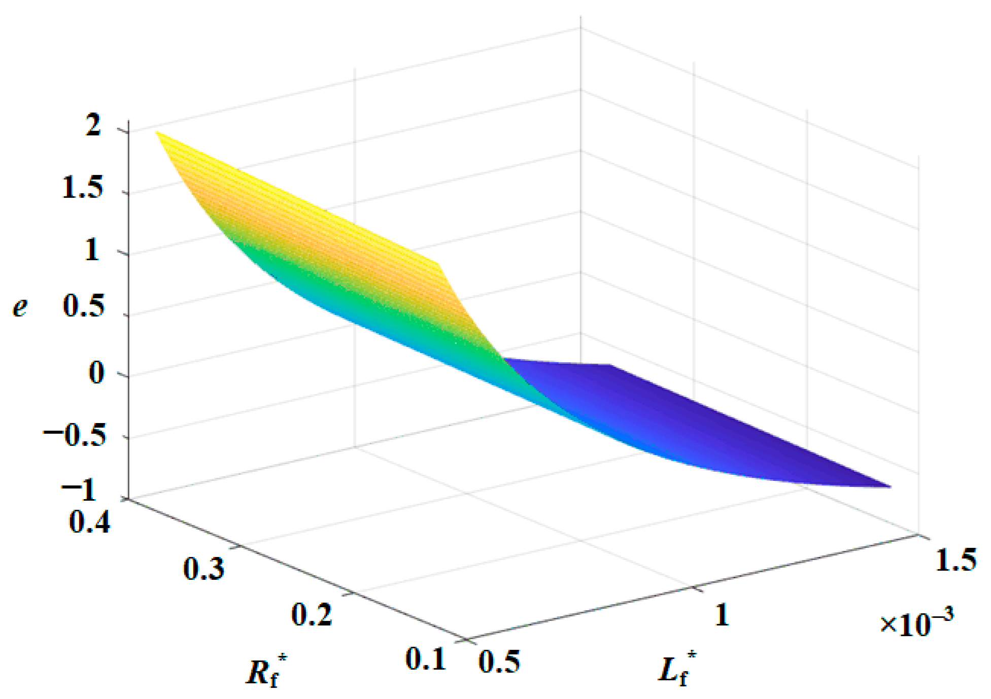
2.3. Parameter Sensitivity Analysis under Wide Frequency Conditions

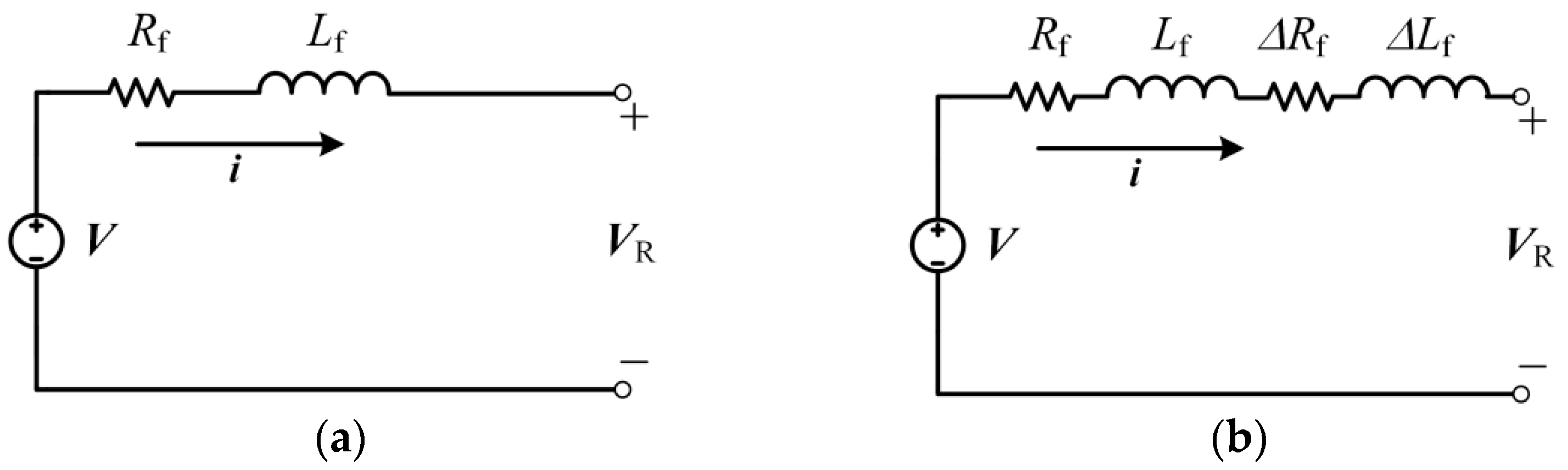
2.3.1. Analysis of Resistive Sensitivity

In the power system of a multi-electric aircraft, the main generator is connected directly to the jet engine through a gearbox, so the frequency of the three-phase AC power varies rapidly, resulting in large temperature variations inside the aircraft. Under such temperature changes, the permeability and saturation point of the filter inductance change, which leads to significant changes in the filter inductance value [19].
The traditional deadbeat direct power control is a control method based on discrete model. Due to the change of external factors, the model parameters do not match the actual parameters, which affects the control effect. In order to evaluate the influence of parameter variation on the model, this section focuses on the sensitivity of parameter variation to deadbeat direct power control.
Firstly, the influence of resistive changes on control is analyzed. According to Equation (8), the model with parameter disturbance is shown as follows:
i [ k + 1 ]   =   T s L f ( V [ k ] ( R f L f T s ) i [ k ] V R [ k ] )
The estimated current value of the actual parameter model at kTs time is:
i * [ k + 1 ]   =   T s L f * ( V [ k ] ( R f * L f * T s ) i [ k ] V R [ k ] )
where i*[k + 1] is the estimated value of the actual current, R f * is the actual value after the change of the line resistance, L f * is the actual value after the change of the line resistance, R f * = Rf + ΔRf, L f * = Lf + ΔLf, where ΔRf and ΔLf are the changes of the line resistance and filter inductance from the actual and given values, respectively.
The error vector e is obtained by making the difference between the estimated current vector of the actual deadbeat direct power control and the current vector estimated by the model with parameter perturbation.
e [ k ]   =   i [ k + 1 ] i * [ k + 1 ]   =   T s ( L f * L f ) V [ k ] L f L f * T s ( L f * L f ) V R [ k ] L f L f * T s ( R f L f * R f * L f ) i [ k ] L f L f *
When the system rating parameter is used in Equation (12), the relationship between the change of the estimated current value and the change of inductance resistance is shown in Figure 3.
When the resistance R f * changes, the error e of current estimation basically does not change, so the influence of resistance on the model is ignored. When the inductance changes from 0.5 mH to 1.5 mH, the error of current estimation will be significantly affected. The reason for the change of inductance value is specifically explored through the expression of inductance, namely:
L   =   0.4 π × μ × N 2 × Afe l
where μ represents the permeability, N is the number of turns of the coil, Afe is the cross-sectional area of the core, l is the length of the magnetic circuit, and the only parameter that can be changed after the inductor is made is the permeability μ. Therefore, the inductance value changes with the change of permeability. For example, Figure 4a shows the relationship between the permeability of a company’s material and temperature change, and Figure 4b shows the relationship between permeability and frequency change.
By observing the above measurement results, it can be concluded that when the permeability of filter inductor is used in different temperature and frequency environments, the actual value will become larger or smaller. The deadbeat direct power control scheme’s performance depends on the accuracy of the model parameters. As the acceleration and deceleration of the engine causes the temperature within the motor to change, the permeability and saturation point of the filter inductor changes, and ultimately the inductance of the filter changes. When the deadbeat direct power control model parameters do not match the actual parameters, the calculated results will deviate and eventually lead to incorrect switching pulse output, resulting in changes in the actual current phase or amplitude, leading to problems, such as reduced power factor and current distortion.

2.3.2. Frequency Sensitivity Analysis

Taking Boeing 787 as an example, the AC power frequency varies in the range of 360 Hz–800 Hz under wide frequency conditions, resulting in the inaccurate calculation of Equation (7). Assuming that the frequency at time kTs is f1, since the frequency changes to f2 at time (k + 1)Ts, the frequency used to calculate the supply voltage vector at (k + 1)Ts at time k is f1. There is an error with the actual frequency at time (k + 1)Ts and the error is Δω = 2π(f2f1). Then, it will affect the calculation of V[k + 1] and the estimation of i[k + 1] and then there will be errors in the calculation of Equation (4). Due to the existence of the control lag, in fact, the vector VR[k] calculated at kTs will be applied at (k + 1)Ts, and its reference value can only be reached at k + 2. The two-step prediction will lead to the frequency variation continuing to expand, increasing the effect on the calculation result.
The expected value of instantaneous active power can form a closed loop through PI and be modified. However, the expected value of instantaneous reactive power in deadbeat direct power control is 0, and there is no instantaneous reactive power feedback loop, so the error generated by reactive power cannot be corrected. Because the change of power frequency is proportional to the change of reactive power [22], the steady-state error of instantaneous reactive power generated by the change of frequency will not be corrected and will continue to accumulate; eventually it will lead to the reduction of power factor.

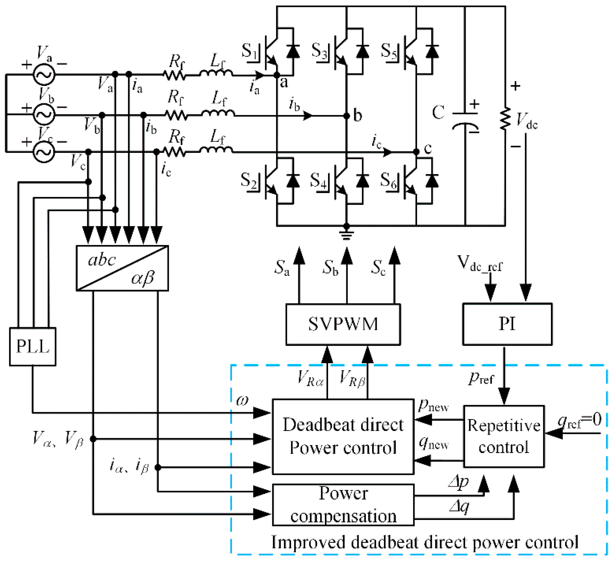
3. Improved Deadbeat Direct Power Control Strategy under Wide Frequency

In order to solve the above problems, this paper adds a method of repetitive control and power compensation on the basis of deadbeat direct power control, which solves the problem of mismatch between the model parameters of line resistance, filter inductor, the actual parameters, and the reactive power bias error caused by frequency variation.

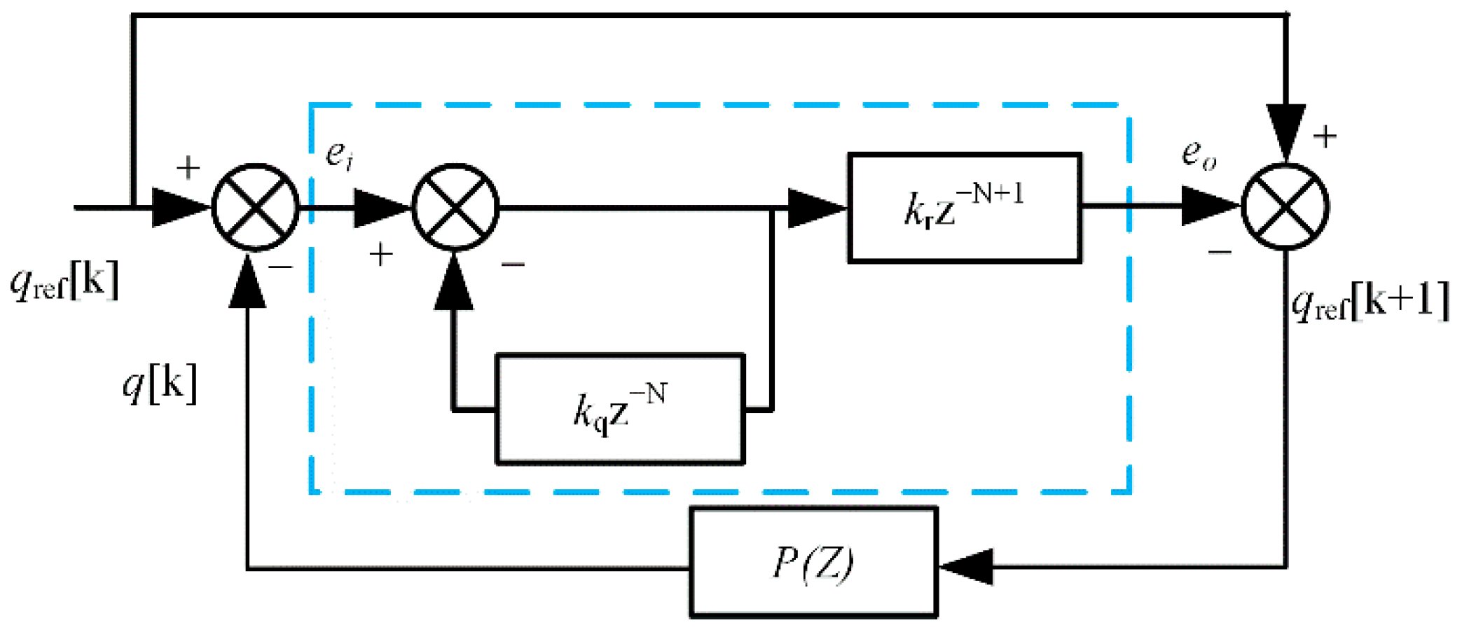
3.1. Repetition Control Strategy

The traditional deadbeat direct power control strategy does not consider the influence of system control frequency variation. In order to solve this problem, the influence of frequency on the system is regarded as periodic error, and the error of the last fundamental period is stored by repeated control, and the waveform is corrected at the appropriate moment of the next fundamental period so as to ensure the output waveform quality in steady state. The block diagram of instantaneous power control based on repeated signal generator is shown in Figure 5. The repeated controller adopts quasi-integral kqz−N, where kq is the quasi-integral coefficient. In order to ensure the stability of the system, 0 < kq < 1 is generally taken. In this paper, kq = 0.95 is taken, and N is the sampling times in a fundamental wave period. In krz−N + 1, z−N is the kr times of the error integral at the same sampling time of the previous fundamental wave period superimposed to the current fundamental wave period, which is used to compensate the predicted value of the fundamental wave period.
kr is the proportionality coefficient, ei and eo are error signals. No matter what the input signal waveform is, if it appears repeatedly in the form of fundamental wave period, the output will be the periodic accumulation of the input signal. The discretization form of the transfer function difference is as follows:
e o ( k )   =   k r e i ( k N + 1 ) + k q u r ( k N )
In the first k a sampling period, according to the control will repeat kTs moment of power projection qref[k + 1] and k times before sampling period prediction error values, the sum of the forecast revisions to instantaneous active power and the instantaneous reactive power for each cycle can inhibit periodic disturbance caused by the frequency change, making its reactive steady-state error close to zero.

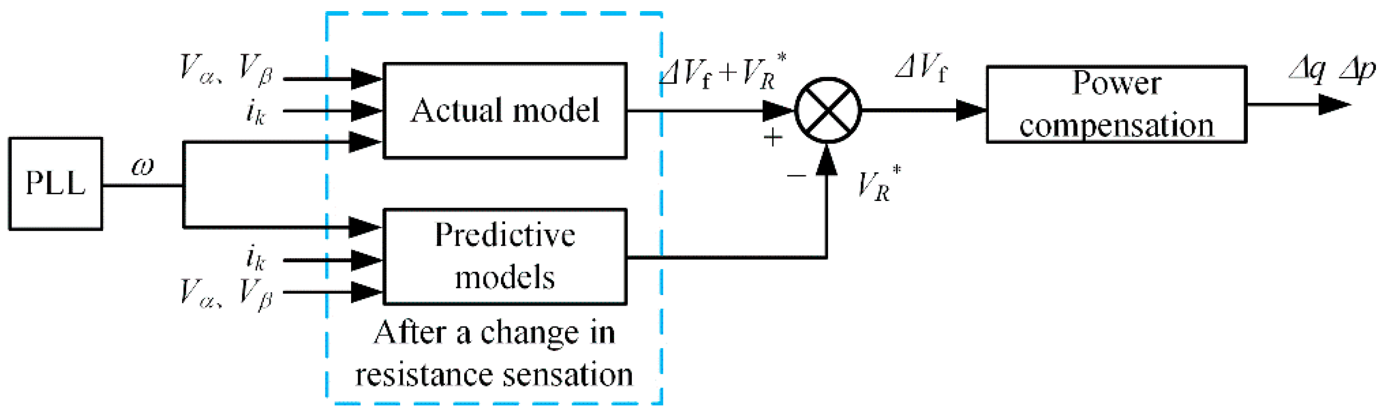
3.2. Power Compensation Strategy

In order to solve the problem that the parameters of the deadbeat direct power control model do not match with the actual parameters in multi-electric aircraft and electric vehicles. In this paper, a power compensation method is proposed. By calculating the power generated by the error amount of the actual parameter deviating from the model parameter and compensating it to the instantaneous power expectation value, the problem caused by parameter mismatch can be solved.
In order to reduce the effects caused by frequency changes, it is first necessary to ensure accurate and fast detection of frequency. In this paper, a three-phase system instantaneous phase-locked loop (PLL) is designed. The parameters of this scheme do not need to be dynamically adjusted and the scheme simplifies the structure of a conventional PLL, reducing the total calculation time. A block diagram of the scheme is shown in Figure 6. The specific function of the first-order low-pass filter in the diagram is to filter the high-frequency noise in the voltage measurement.
The ideal model of the system is shown in Figure 7a. Assuming that the inductor resistance does not change and is in a stable state, the system model expression at this time is:
V R   =   V     R f i     L f d i d t
When the inductive resistance changes, the system model is shown in Figure 7b, where ΔRf and ΔLf are the changes of the actual line resistance and filter inductance relative to the model parameters. Let ΔVRf and ΔVLf be the voltage vectors generated by this variation, then the model after the resistance change is:
Δ V R f   +   Δ V L f   +   V R   =   V     R f i     L f d i d t
Assuming that the resistive changes between time (k − 1)Ts and kTs, then at time (k − 1)Ts, the current at time kTs is estimated by deadbeat direct power control without considering the change of parameters, and the current value is expressed by vector i*, then the discrete model equation is:
V R * [ k ]   =   V [ k ]     R f i * [ k ]     L f T s ( i [ k + 1 ] i * [ k ] )
The formula used to calculate the actual sampled current value at kTs time is:
Δ V f [ k ]   +   V R * [ k ]   =   V [ k ]     R f i [ k ] L f T s ( i [ k + 1 ] i [ k ] )
where ΔVf[k] = ΔVRf + ΔVLf, due to the inductance change, the voltage vector at the rectifier side becomes the sum of the voltage vector at the rectifier side when the inductance does not change, and the voltage vector generated by the resistive change. By subtracting Equations (17) and (18), we can obtain:
Δ V f [ k ]   =   R f ( i [ k ] i * [ k ] ) + L f T s ( i [ k ] i * [ k ] ) =   Δ V f α [ k ] + j Δ V f β [ k ]
Through this equation, the components of the resistive change in the stationary coordinate system can be obtained, and then the instantaneous active power and instantaneous reactive power can be obtained by the following equation:
{ Δ p [ k ]   =   Δ V f α [ k ] i α [ k ] + Δ V f β [ k ] i β [ k ] Δ q [ k ]   =   Δ V f β [ k ] i α [ k ] Δ V f α [ k ] i β [ k ]
Here, Δqf and Δpf represent the instantaneous active and reactive power generated by the resistive change, respectively. The instantaneous active and reactive power generated by the resistive and inductance change can be obtained by bringing the instantaneous active and reactive power into the power reference value after repeated change:
{ p new [ k + 1 ]   =   p ref [ k + 1 ] + Δ p [ k ] q new [ k + 1 ]   =   q ref [ k + 1 ] + Δ q [ k ]
where pnew and qnew are the expected value of instantaneous active power and the expected value of reactive power after improvement respectively.
By adding the power compensation to the output of the repetitive control, the advantages of eliminating periodic errors of the original repetitive control are preserved, and the stability of the control system can be guaranteed when the model parameters are not matched. The control block diagram of the proposed power compensation strategy is shown in Figure 8.

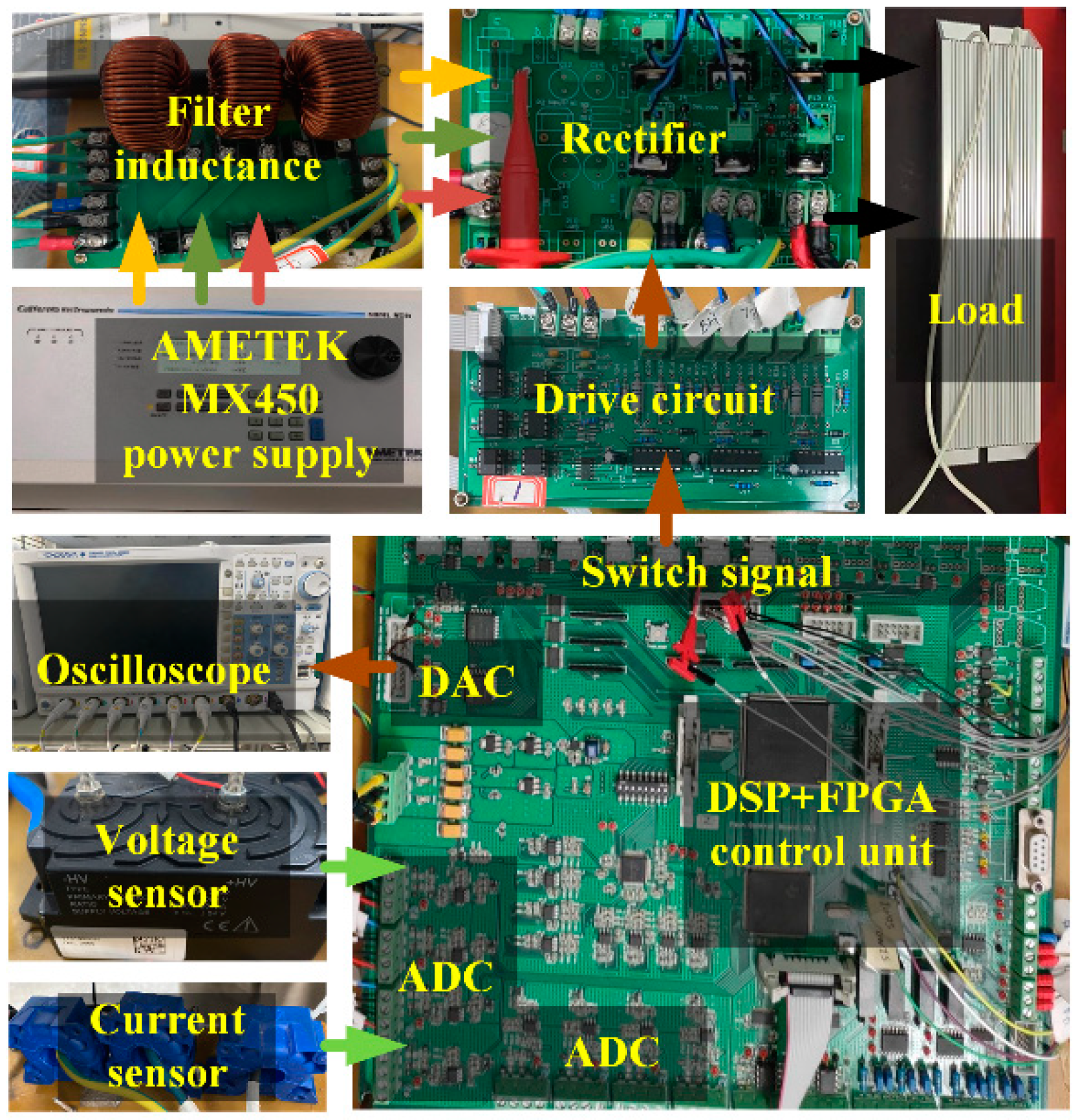
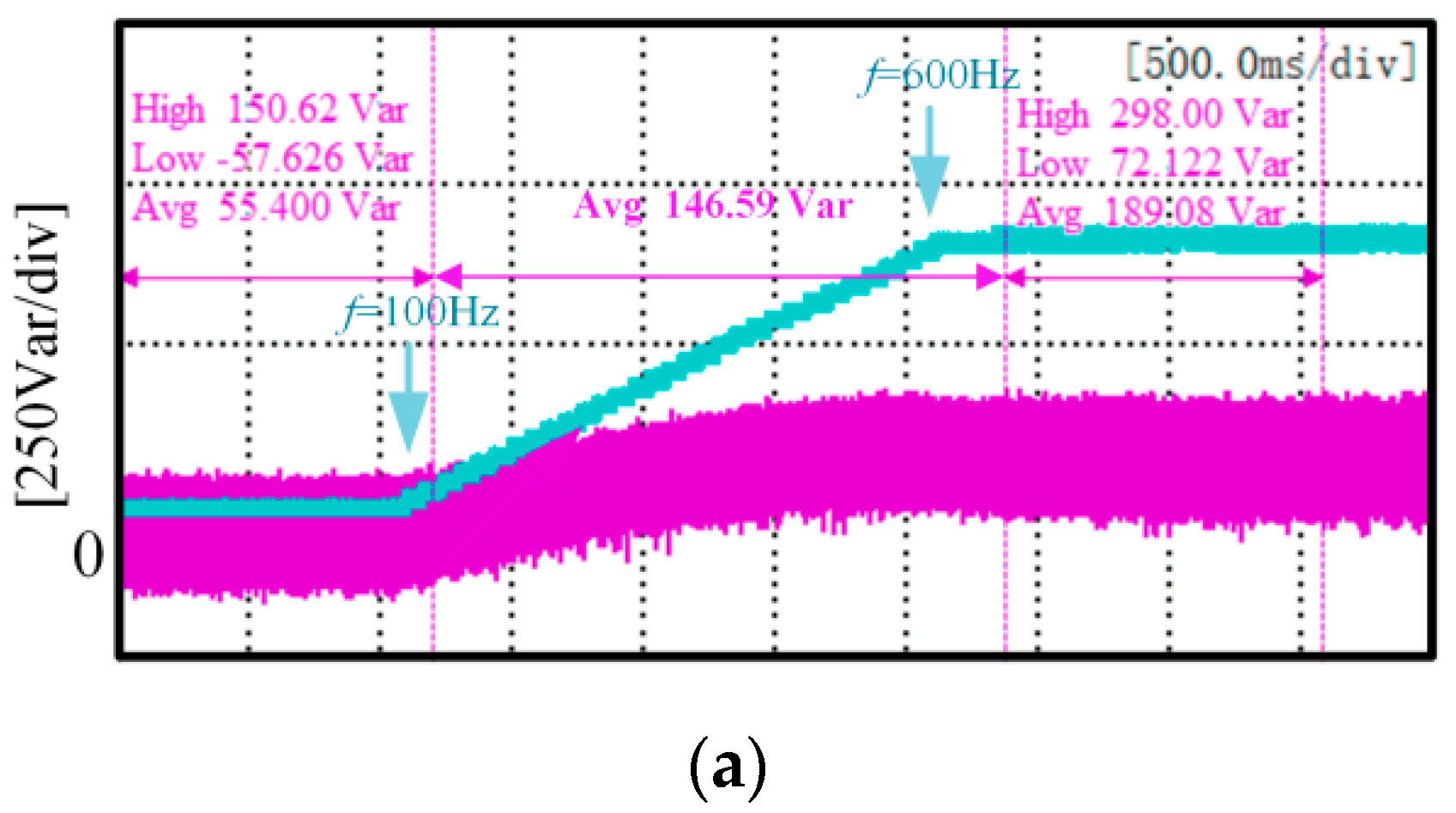
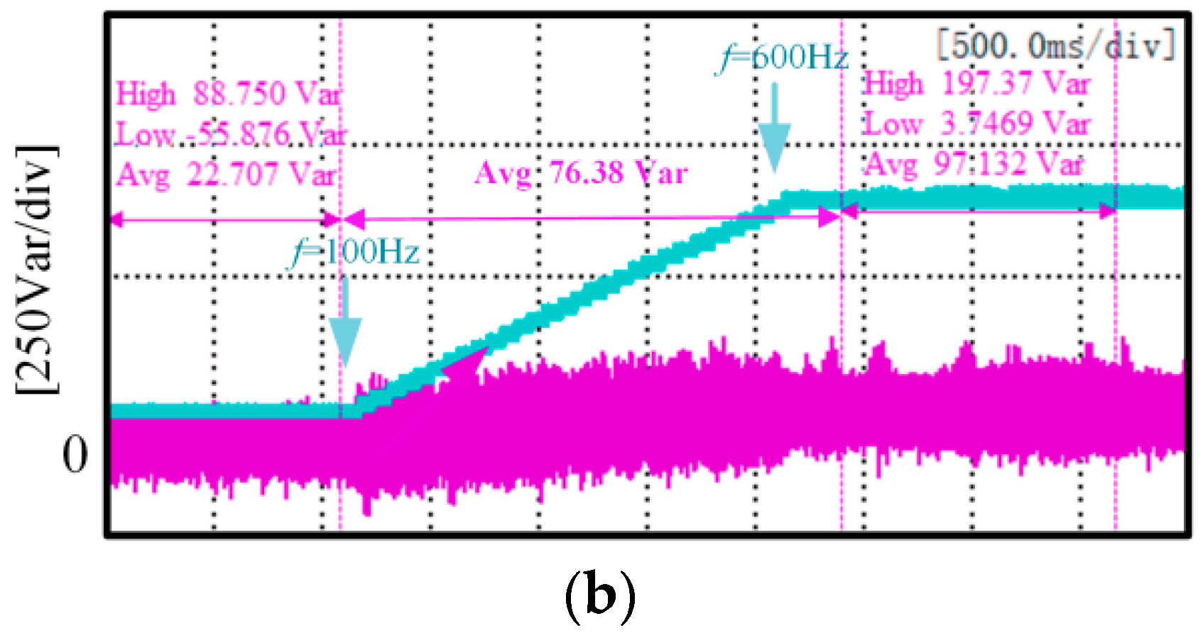
4. Experimental Results and Analysis

In order to verify the effectiveness and accuracy of theoretical analysis of the wide frequency rectifier based on the improved deadbeat direct power control, an experimental platform for the control system is built, as shown in Figure 9. In this paper, experimental comparisons are made between the traditional deadbeat direct power control and the improved deadbeat direct power control proposed in this paper. The specific simulation and experimental parameters are shown in Table 1.
In this paper, a 1 kW voltage PWM rectifier system is built. The implementation of the algorithm is based on DSP(TMS320F28335) produced by TI company and FPGA(EP1C6Q240C8) produced by ALTER company. The main frequency of DSP is 150 MHz. The A/D conversion is realized by the A/D module inside DSP. AMETEK MX45 programmable grid simulator is used as variable frequency three-phase power supply, and Mitsubishi IPM is used as switch tube. The built experimental platform is shown in Figure 9.
The experimental results were recorded by a Yokogawa DLM4058 digital oscilloscope, and the PWM signal was obtained by logic probe PBL100. The current sensor used LF210-S of Lyme Company, and the voltage sensor used DVL2000 of Lyme Company. The pulse-width modulation switching frequency is 20 kHz, and the sampling time of the controller is 50 μs. The DC side voltage is 270 V, and the DC side resistance value is 72.9 Ω. The DC side voltage and the given voltage value are adjusted by PI, and the output value is the expected instantaneous active power. The PI parameters of the voltage outer loop are Kp = 5 and Ki = 8.

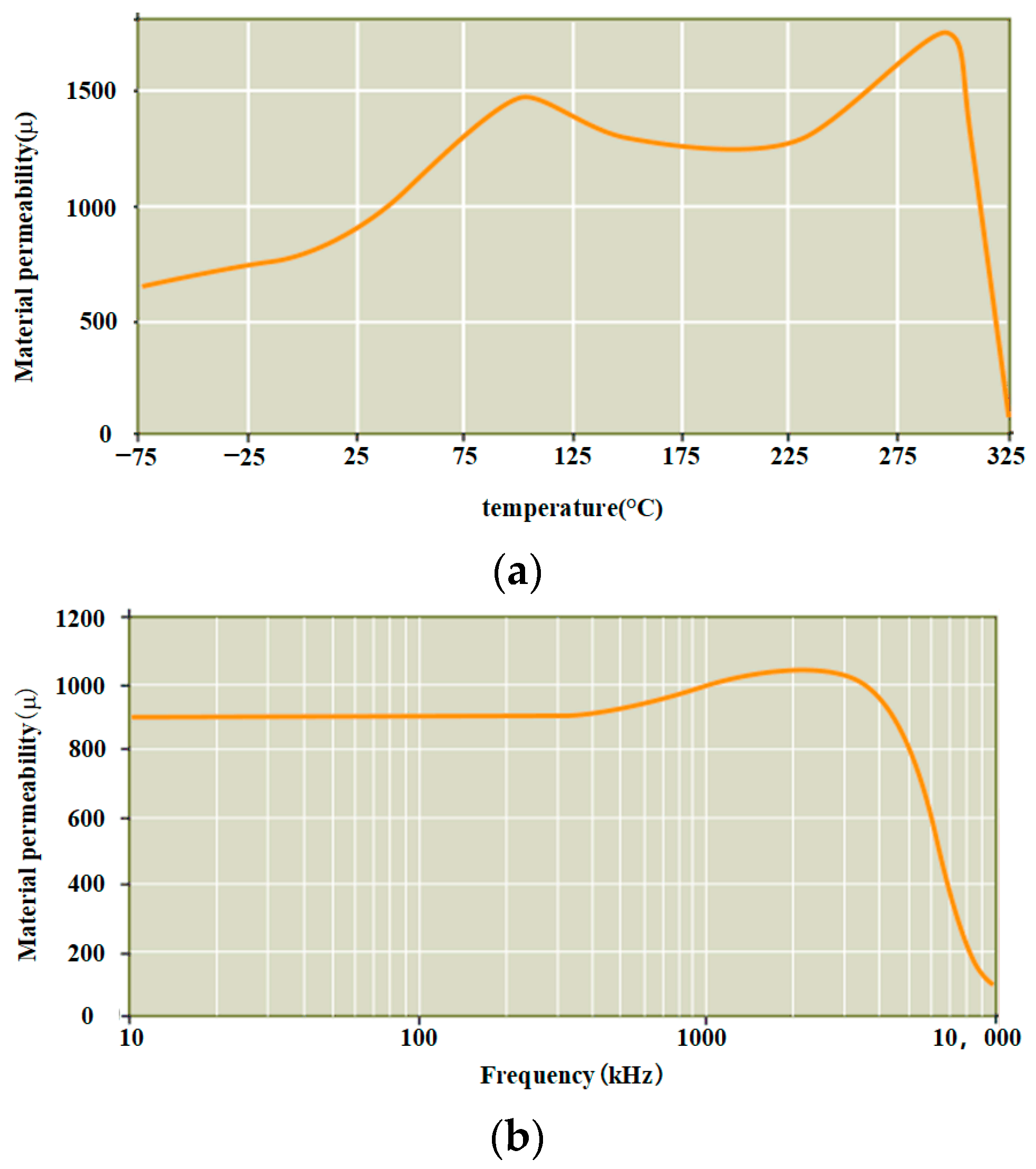
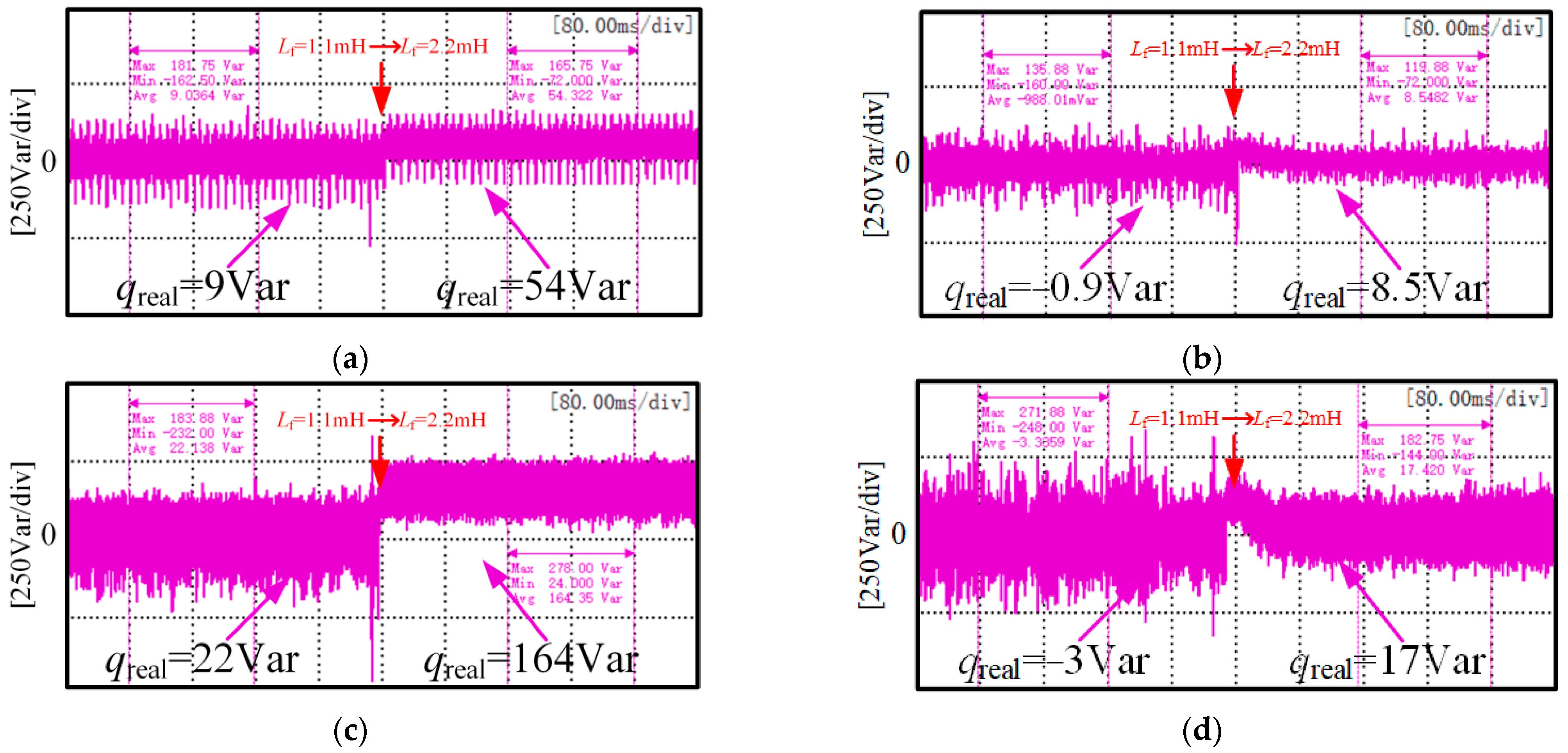
4.1. Influence of Frequency Variation on Inductance

To verify the change of inductance with frequency, the value of filter resistance inductance with frequency measured by RLC table is shown in Table 2.
It can be seen from Table 2 that when the frequency rises at room temperature of 25 °C, the inductance value decreases, which verifies that the inductance will change with the frequency, and the change of inductance value will be larger with the increase of temperature. The analysis is based on the example of a multi-electric aircraft operating at a much wider frequency. A detailed description is given below.

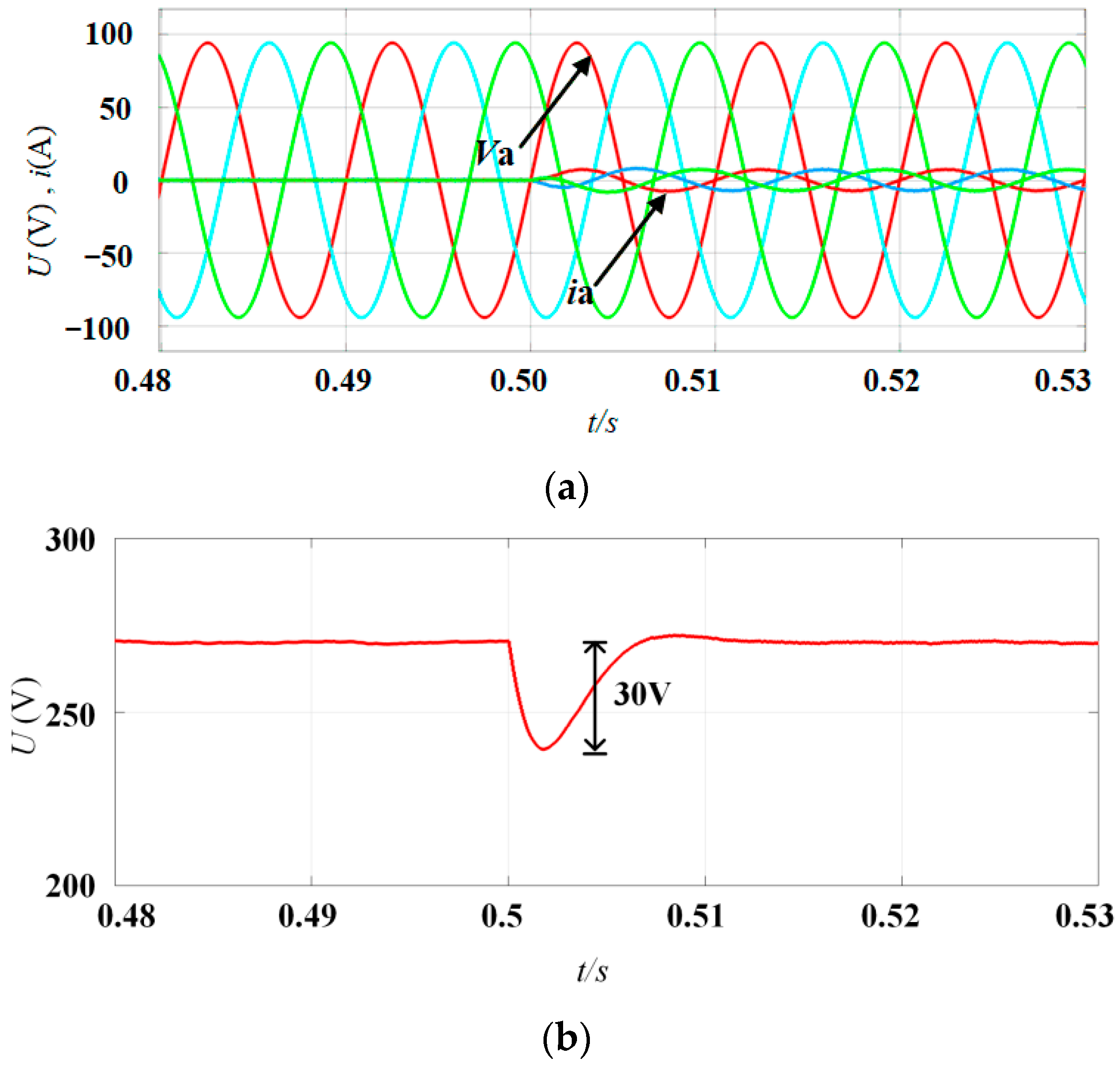
4.2. Feasibility Verification Analysis

Figure 10a shows the steady-state waveform of the three-phase grid voltage and input current under the condition of 72.9 Ω resistance load. According to the simulation results, the input current of each phase is basically consistent with the corresponding input voltage phase, and the unit power factor operation of the PWM rectifier is realized. In addition, in order to verify the method of dynamic characteristic, for PWM rectifier from no-load (load end open circuit) to 1 kw resistive load test. The simulation results of Figure 10b can be seen that the DC side voltage drops close to 30 V when the load changes. After 0.014 s, it returns to the steady state. The voltage fluctuation is basically zero and the fluctuation amplitude is 0.5 V, which has a high accuracy and a fast response speed.

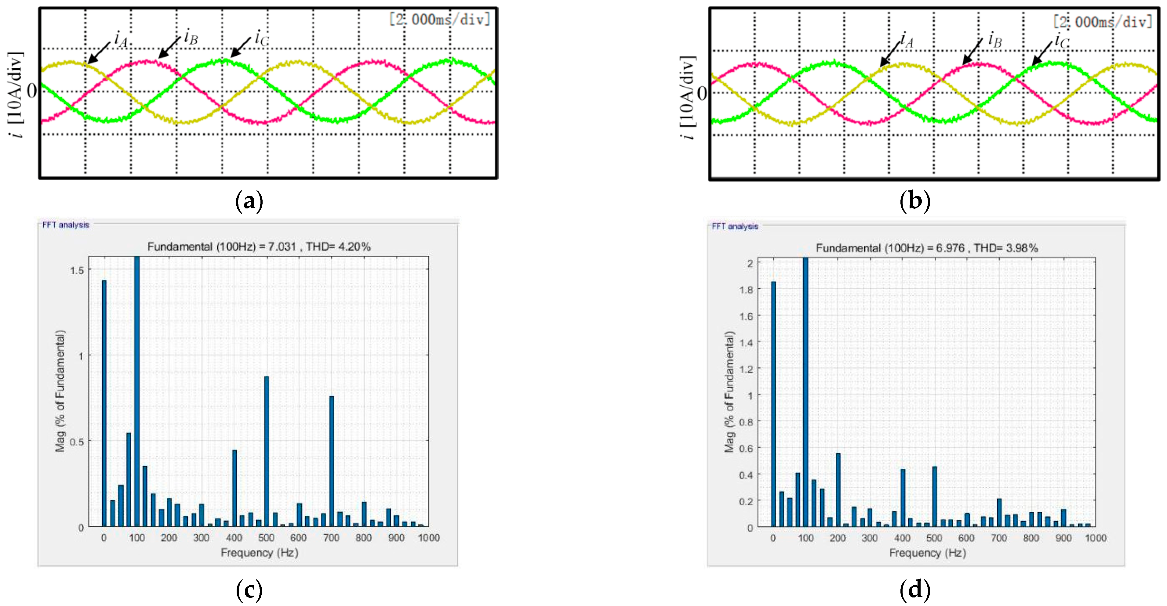
4.3. Dynamic Performance Comparison

The acceleration and deceleration of the engine causes the temperature inside the motor to change. As seen in Figure 4a, the filter inductor permeability changes due to temperature variation, with the maximum permeability being approximately 200% of that at 25 °C. According to Equation (13), the inductance of the filter is proportional to the permeability when its parameters, such as coil length and cross-sectional area are determined. Therefore, to demonstrate the effectiveness of the proposed method when the inductance parameters are mismatched, this paper uses a contactor and a 1.1 mH inductor as a bypass to make a sudden change in inductance to 200% of the initial value.
Figure 11a,b show the values of reactive power at a frequency of 100 Hz for abrupt inductor change and stable inductor operation, respectively. As the filter inductance rises to 2.2 mH, a step in reactive power exists for the conventional method (left). The average value of reactive power changes from 9 Var to 54 Var, with an oscillation of 45 Var. The reactive power of the proposed solution is significantly reduced when the inductor is stable compared to the conventional method. When the inductor changes, the average value of reactive power changes from −0.9 Var to 8.5 Var, with an oscillation of 9.4 Var, which is only 17.4% of the conventional method. The proposed method is even more effective at 400 Hz, as seen in Figure 11c,d, where the reactive power oscillation is only 10.7% of the conventional method when the inductance changes.
Figure 12a,b show the waveform of the voltage and current in phase A when the inductance of the proposed scheme changes. The current on the AC side does not fluctuate greatly, that is, the unit power factor can be maintained.
The total current harmonic distortion of the traditional deadbeat direct power control method is larger than that of the proposed method in a steady state operation. The comparison of the two methods at 100 Hz is shown in Figure 12c,d. The total harmonic distortion of the traditional deadbeat direct power control method is 4.2%, while the total current harmonic distortion of the proposed method is 3.98%. A higher THD wave will reduce the capacity of the system, accelerate the aging speed of equipment or even damage, endanger the safety and stability of production, waste energy, etc. The THD of the improved method is significantly better than that of the traditional control method.
Figure 13 shows the DC side voltage and reactive power change waveform when the frequency rises in a ramp form. To further simulate the operation of the actual working conditions, according to the aircraft electric characteristic standard MIL-STD-704, the three-phase AC voltage frequency changes from 100 Hz to 600 Hz at 250 Hz/s. The blue curves in Figure 13a,b indicate the change in frequency. The average reactive power value of the proposed scheme at 100 Hz is 40% of the conventional deadbeat direct power control scheme, and the average reactive power is reduced by 33 Var compared to the conventional method. The amount of reactive power fluctuation is 69.2% of the conventional scheme. After a frequency change to 600 Hz, the average reactive power value of the proposed scheme is 51.2% of that of the conventional method, which is 92 Var lower than the average reactive power value of the conventional method—54.3% of the reactive power fluctuation of the conventional scheme. In the interval where the frequency changes, the experimental results compare only the average values, as the maximum and minimum values of reactive power are always changing. In the interval where the frequency varies, it can be observed that the reactive power can be reduced to 52.1% of the conventional method using the proposed method. Therefore, the overall power factor of the proposed scheme is higher in a steady state, and the overall fluctuation is less stable. This experiment can verify that the proposed method has the advantages of a high power factor and a high stability

5. Conclusions

In this paper, an improved deadbeat direct power control method is designed by using deadbeat direct power control, repetitive control and power compensation. The traditional control strategy does not consider the frequency change of the AC side and the influence brought by it. The improved method proposed in this paper, on the one hand, reduces the periodic influence brought by the frequency change, and on the other hand, ensures the stable operation of the system when the model parameters do not match the actual parameters. The specific advantages of the proposed control strategy are as follows:
  • The proposed method solves the reactive steady-state error problem caused by the frequency change, and improves the power quality;
  • The proposed method effectively solves the problem of inaccurate model calculation caused by the variation of resistive parameters and improves the stability in the application field.

Author Contributions

Data curation, K.B.; formal analysis, S.L.; funding acquisition, W.C. and G.Z.; investigation, S.L. and W.S.; methodology, Z.L.; project administration, W.C. and G.Z.; resources, W.S.; validation, K.B.; writing—original draft, S.L. and K.B.; writing—review and editing, W.S. and W.C. All authors have read and agreed to the published version of the manuscript.

Funding

This research was funded by the National Natural Science Foundation of China, grant number 52077156; the Key Program of Tianjin Natural Science Foundation, grant number 20JCZDJC00020; and the Zhejiang Provincial Basic Public Welfare Research Projects, grant number LGG22E070011.

Data Availability Statement

Not applicable.

Conflicts of Interest

Wenbo Sun is an employee of WEICHAI Power Co., Ltd., Shandong 261061, China. The paper reflects the views of the scientists and not the company.

References

  1. Sarlioglu, B. Advances in AC-DC power conversion topologies for More Electric Aircraft. In Proceedings of the 2012 IEEE Transportation Electrification Conference and Expo (ITEC), Dearborn, MI, USA, 18–20 June 2012; pp. 1–6. [Google Scholar]
  2. Chandran, V.; Patil, C.K.; Karthick, A.; Ganeshaperumal, D.; Rahim, R.; Ghosh, A. State of Charge Estimation of Lithium-Ion Battery for Electric Vehicles Using Machine Learning Algorithms. World Electr. Veh. J. 2021, 12, 38. [Google Scholar] [CrossRef]
  3. Cao, W.; Mecrow, B.C.; Atkinson, G.J.; Bennett, J.W.; Atkinson, D.J. Overview of Electric Motor Technologies Used for More Electric Aircraft (MEA). IEEE Trans. Ind. Electron. 2012, 59, 3523–3531. [Google Scholar]
  4. Wang, Y.; Nuzzo, S.; Zhang, H.; Zhao, W.; Gerada, C.; Galea, M. Challenges and Opportunities for Wound Field Synchronous Generators in Future More Electric Aircraft. IEEE Trans. Transp. Electron. 2020, 6, 1466–1477. [Google Scholar] [CrossRef]
  5. Monroy, A.O.; Le-Huy, H.; Lavoie, C. Modeling and simulation of a 24-pulse Transformer Rectifier Unit for more electric aircraft power system. In Proceedings of the 2012 Electrical Systems for Aircraft, Railway and Ship Propulsion, Bologna, Italy, 16–18 October 2012; pp. 1–5. (In Italian). [Google Scholar]
  6. Meng, F.; Gao, L.; Yang, S.; Yang, W. Effect of Phase-Shift Angle on a Delta-Connected Autotransformer Applied to a 12-Pulse Rectifier. IEEE Trans. Ind. Electron. 2015, 62, 4678–4690. [Google Scholar] [CrossRef]
  7. Gong, G.; Heldwein, M.L.; Drofenik, U.; Minibock, J.; Mino, K.; Kolar, J.W. Comparative evaluation of three-phase high-power-factor AC-DC converter concepts for application in future More Electric Aircraft. IEEE Trans. Ind. Electron. 2005, 52, 727–737. [Google Scholar] [CrossRef]
  8. Liu, B.; Ren, R.; Jones, E.A.; Wang, F.; Costinett, D.; Zhang, Z. A Modulation Compensation Scheme to Reduce Input Current Distortion in GaN-Based High Switching Frequency Three-Phase Three-Level Vienna-Type Rectifiers. IEEE Trans. Power Electron. 2018, 33, 283–298. [Google Scholar] [CrossRef]
  9. Borovic, U.; Zhao, S.; Silva, M.; Bouvier, Y.E.; Vasić, M.; Oliver, J.A.; Alou, P.; Cobos, J.A.; Árevalo, F.; García-Tembleque, J.C.; et al. Comparison of three-phase active rectifier solutions for avionic applications: Impact of the avionic standard DO-160 F and failure modes. In Proceedings of the 2016 IEEE Energy Conversion Congress and Exposition (ECCE), Milwaukee, WI, USA, 18–22 September 2016; pp. 1–8. [Google Scholar]
  10. Yan, S.; Yang, Y.; Hui, S.Y.; Blaabjerg, F. A Review on Direct Power Control of Pulsewidth Modulation Converters. IEEE Trans. Power Electron. 2021, 36, 11984–12007. [Google Scholar] [CrossRef]
  11. Malinowski, M.; Jasinski, M.; Kazmierkowski, M.P. Simple Direct Power Control of Three-Phase PWM Rectifier Using Space-Vector Modulation (DPC-SVM). IEEE Trans. Ind. Electron. 2004, 51, 447–454. [Google Scholar] [CrossRef]
  12. Kazmierkowski, M.P.; Jasinski, M.; Wrona, G. DSP-Based Control of Grid-Connected Power Converters Operating Under Grid Distortions. IEEE Trans. Ind. Inf. 2011, 7, 204–211. [Google Scholar] [CrossRef]
  13. CortÉs, P.; RodrÍguez, J.; Antoniewicz, P.; Kazmierkowski, M. Direct Power Control of an AFE Using Predictive Control. IEEE Trans. Power Electron. 2008, 23, 2516–2523. [Google Scholar] [CrossRef]
  14. Bi, K.; Xu, Y.; Zeng, P.; Chen, W.; Li, X. Virtual Flux Voltage-Oriented Vector Control Method of Wide Frequency Active Rectifiers Based on Dual Low-Pass Filter. World Electr. Veh. J. 2022, 13, 35. [Google Scholar] [CrossRef]
  15. Jlassi, I.; Estima, J.O.; Khojet El Khil, S.; Bellaaj, N.M.; Cardoso, A.J.M. Multiple Open-Circuit Faults Diagnosis in Back-to-Back Converters of PMSG Drives for Wind Turbine Systems. IEEE Trans. Power Electron. 2015, 30, 2689–2702. [Google Scholar] [CrossRef]
  16. Kang, L.; Zhang, J.; Zhou, H.; Zhao, Z.; Duan, X. Model Predictive Current Control with Fixed Switching Frequency and Dead-Time Compensation for Single-Phase PWM Rectifier. Electronics 2021, 10, 426. [Google Scholar] [CrossRef]
  17. Yang, H.; Zhang, Y.; Liang, J.; Liu, J.; Zhang, N.; Walker, P.D. Robust deadbeat predictive power control with a discrete-time disturbance observer for PWM rectifiers under unbalanced grid conditions. IEEE Trans. Power Electron. 2018, 34, 287–300. [Google Scholar] [CrossRef] [Green Version]
  18. Young, H.A.; Perez, M.A.; Rodriguez, J. Analysis of finite-control-set model predictive current control with model parameter mismatch in a three-phase inverter. IEEE Trans. Ind. Electron. 2016, 63, 3100–3107. [Google Scholar] [CrossRef]
  19. Easley, M.; Fard, A.Y.; Fateh, F.; Shadmand, M.B.; Abu-Rub, H. Auto-tuned Model Parameters in Predictive Control of Power Electronics Converters. In Proceedings of the 2019 IEEE Energy Conversion Congress and Exposition (ECCE), Baltimore, MD, USA, 29 September–3 October 2019; pp. 3703–3709. [Google Scholar]
  20. Benzaquen, J.; Shadmand, M.B.; Mirafzal, B. Ultrafast Rectifier for Variable-Frequency Applications. IEEE Access 2019, 7, 9903–9911. [Google Scholar] [CrossRef]
  21. Zhao, W.; Jiao, S.; Chen, Q.; Xu, D.; Ji, J. Sensorless Control of a Linear Permanent-Magnet Motor Based on an Improved Disturbance Observer. IEEE Trans. Ind. Electron. 2018, 65, 9291–9300. [Google Scholar] [CrossRef]
  22. Dong, T.; Zhu, C.; Zhou, F.; Zhang, H.; Lu, F.; Zhang, X. Innovated Approach of Predictive Thermal Management for High-Speed Propulsion Electric Machines in More Electric Aircraft. IEEE Trans. Transp. Electron. 2020, 6, 1551–1561. [Google Scholar] [CrossRef]
Figure 1. Control system block diagram.
Wevj 13 00230 g001
Figure 2. Topological structure of main circuit of a three-phase voltage source-type PWM rectifier.
Wevj 13 00230 g002
Figure 3. The influence of resistance parameter changes on the model.
Wevj 13 00230 g003
Figure 4. The change of permeability of L material: (a) L Relationship between material permeability and temperature; (b) L Relationship between material permeability and frequency.
Wevj 13 00230 g004
Figure 5. Repetitive control system.
Wevj 13 00230 g005
Figure 6. Instantaneous PLL.
Wevj 13 00230 g006
Figure 7. PWM Rectifier Single-Phase System Model: (a) Ideal single-phase system model. (b) Actual single-phase system model.
Wevj 13 00230 g007
Figure 8. Control block diagram of the proposed power compensation strategy.
Wevj 13 00230 g008
Figure 9. Experimental platform.
Wevj 13 00230 g009
Figure 10. Feasibility Analysis: (a) three-phase AC voltage and three-phase AC current; (b) DC-link voltage.
Wevj 13 00230 g010
Figure 11. Comparison of reactive power variation under different frequency when inductance changes suddenly: (a) Inductance change of traditional control scheme at 100 Hz; (b) Inductance change of proposed control scheme at 100 Hz; (c) Inductance change of traditional control scheme at 400 Hz; (d) Inductance change of proposed control scheme at 400 Hz.
Wevj 13 00230 g011
Figure 12. Comparison of three-phase current waveforms and THD: (a) the three-phase current waveform of the conventional deadbeat direct power control; (b) the three-phase current waveform of the proposed scheme; (c) THD of conventional deadbeat direct power control current; (d) THD of proposed scheme current.
Wevj 13 00230 g012
Figure 13. Dynamic performance under supply frequency changes: (a) Frequency variation and reactive power of conventional control schemes; (b) Improved control scheme frequency variation and reactive power.
Wevj 13 00230 g013aWevj 13 00230 g013b
Table 1. Parameters of the system.
ParameterSymbolsValues
DC-link voltageVdc270 V
Effective value of AC voltageVpcc115 V
Filter resistanceRf0.25 Ω
Filter inductanceLf1.1 mH
DC-link capacitanceC200 μF
Table 2. The relationship between inductance and frequency change.
Frequency/HzInductance Lf/mH
1001.0479
3001.0462
5001.0457
7001.0450
8001.0448
Publisher’s Note: MDPI stays neutral with regard to jurisdictional claims in published maps and institutional affiliations.

