Article

Performance Simulation of Long-Stator Linear Synchronous Motor for High-Speed Maglev Train under Three-Phase Short-Circuit Fault

College of Electrical Engineering, Zhejiang University, Hangzhou 310027, China
*
Author to whom correspondence should be addressed.
World Electr. Veh. J. 2022, 13(11), 216; https://doi.org/10.3390/wevj13110216
Submission received: 27 September 2022 / Revised: 3 November 2022 / Accepted: 14 November 2022 / Published: 18 November 2022

Abstract

:
The high-speed Maglev train is driven by long-stator linear synchronous motors (LLSM). During the long-time outdoor operation, the insulation material of the armature winding may be damaged, either due to aging or the movement of the windings. This may result in the three-phase short-circuit fault, which affects the traction performance and the operation of the train. In this paper, a simulation model of the high-speed Maglev train traction system with a three-phase short-circuit fault LLSM is established, including the converters at two ends, feeder cables, segmented LLSM and traction control system. The system adopts a double-end power supply mode. The model divides the fault segment LLSM into two parts. One part is connected to the converter, which is equivalent to a normal operating segment with shortened long-stator. The other part is equivalent to a three-phase short-circuit linear generator. Based on this model, the influence of running speed and fault segment length on the traction performance of the train is simulated. In addition, the stator current, acceleration and traction force of the Maglev train during fault segment are investigated in the acceleration phase, deceleration phase and constant speed phase, respectively. The results can provide a reference for three-phase short-circuit fault diagnosis.

1. Introduction

The running speed of traditional high-speed railways is limited by pantographs and wheel-rails. High-speed Maglev trains use a Long-stator Linear Synchronous Motor (LLSM) to achieve contactless suspension. As there is no wear and friction, the running speed of Maglev trains can reach more than 600 km/h. In addition, the Maglev trains also have the advantages of safety, stability, comfort and no noise [1,2].
After long-time operation in the outdoor environment, the stator windings of the Maglev train will move relative to each other. The wear and damage to the insulating layer, caused by the movement of the stator windings or by the aging of the insulating material, may lead to a three-phase short-circuit fault. The fault point may occur in the long stator segment or feeder cable [3]. The electromagnetic thrust generated by the train will change significantly after the fault, affecting the train’s running speed, running safety and riding comfort. Therefore, it is very important to study the influence of three-phase short-circuit faults on train running performance.
Research on the Maglev train has mainly focused on magnetic levitation, guidance, propulsion and power supply. In terms of fault analysis and fault simulation of Maglev trains, a method for detecting inter-chip short-circuit faults between long stators based on fractal dimensions is proposed and simulated [4]. The impact of the power supply system on the grid under different fault conditions is also studied through a simulation model [5]. As in the fault-tolerant control for the magnetic levitation system of high-speed Maglev train, a fault-tolerant control system with a state observer is constructed to improve the redundancy [6]. There is also a study exploring the fault-tolerant control scheme for permanent-magnet linear motor traction systems with open-phase fault [7]. The current research on Maglev train faults is mainly aimed at the linear motor itself or the traction power supply terminal. However, there is not much research on the impact of the three-phase short-circuit fault of LLSM on the running performance of the train.
This paper introduces the working mode of the high-speed Maglev train in a normal operation state and establishes the three-phase short-circuit fault model of a LLSM for high-speed Maglev train. The short process when the train passes through the three-phase short-circuit fault point is analyzed. Then, the impact of the three-phase short-circuit fault on the running performance of the Maglev train, at different stages of operation, is studied, including the acceleration phase, deceleration phase and constant speed phase.

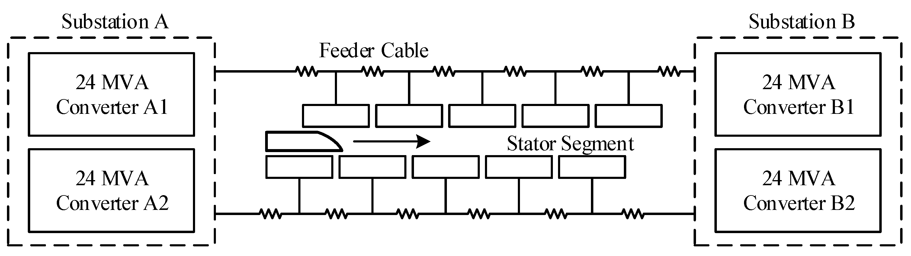
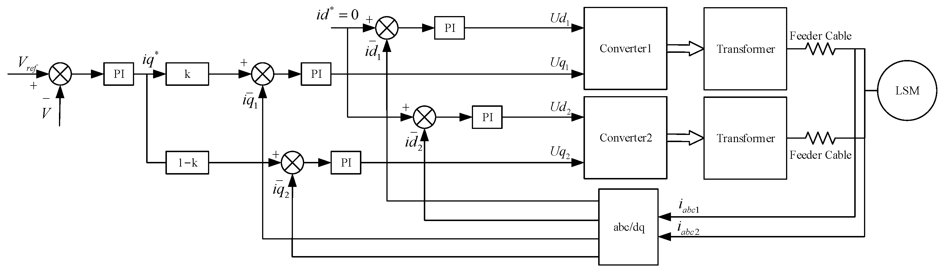
2. Traction Power Supply System of High-Speed Maglev Train

The traction power supply system of the high-speed Maglev train is composed of a traction grid, step-down transformer, high-power converter(including rectifier and inverter), feeder cables and segmented LLSM [8,9]. The excitation winding is mounted underneath the vehicle body and the excitation current is controlled by the suspension system to keep the suspension air gap constant. The core drive unit of the high-speed Maglev is a LLSM, of which stator winding is laid on the track. After a LLSM is supplied with a three-phase variable frequency current, there will be an armature traveling wave magnetic field. The electromagnetic thrust is generated when the armature magnetic field and the excitation magnetic field run synchronously to realize the horizontal movement of the vehicle [10]. In order to improve the operation efficiency, the segmented power supply to the stator on the track is adopted. To improve the system capacity and obtain a higher acceleration, the double-end power supply system is required [11,12]. As shown in Figure 1, the substation A and substation B at each end supply power to each stator segment in parallel through their respective feeder cables [13]. There will be a large impedance voltage drop as a result of the long feeder cables.
In the double-end power supply mode of the high-speed Maglev train, the traditional direct mode method can be used for the traction control strategy. The circulating current and total current are directly used as control targets to ensure that the two converters output the same current. The system will generate a large loss because of the differences in the cable impedance, particularly when the train is close to a substation on one side. In order to solve this problem, a control strategy based on the lowest loss can also be used. The output current of one side converter is inversely proportional to the resistance of the connected feeder cable. The current ratio of the two converters needs to be adjusted in real time to achieve the lowest total loss of the feeder cables on both sides [14,15,16].
The control strategy of the whole system in this paper is shown in Figure 2. This control method includes two control loops: the speed loop and the current loop. In order to realize the decoupling control of thrust and levitation force, the control method with i d = 0 is adopted [17,18,19]. To provide the maximum current for the LLSM, this paper maintains the output currents of the two power converts in the same phase and frequency. The strategy also adjusts the current distribution ratio k , dynamically, to reduce losses and improve efficiency. The long feeder cable end with a large impedance receives a small current while the short feeder cable end with a small impedance receives a large current. The output currents of converter 1 and converter 2 are as follows:
{ i d 1 * = i d 2 * = 0 i q 1 * = k i q * i q 2 * = ( 1 k ) i q *
where ( i d 1 * , i q 1 * ) are the d-axis and q-axis component of convert 1 output current, ( i d 2 * , i q 2 * ) are the d-axis and q-axis component of convert 2 output current.
Due to the continuous increase in the voltage drop on the feeder cable and the back Electromotive Force (EMF) in the LLSM during the acceleration process, the required stator current cannot be provided by the converter. Thus, the traction system adopts three-level transformer voltage ratios to achieve the running speed of 600 km/h.
The converter capacity is S = 3 U 0 m a x I 0 m a x , where U 0 m a x and I 0 m a x are the maximum phase voltage and phase current, respectively. The three-level transformation voltage ratios used are k 1 = 1.7 , k 2 = 2.6 , k 3 = 3.5 . The voltage and current limits that can be provided by the converter are as follows:
U 1 max = k 1 U 0 max ,   I 1 max = I 0 max / k 1
U 2 max = k 2 U 0 max ,   I 2 max = I 0 max / k 2
U 3 max = k 3 U 0 max ,   I 3 max = I 0 max / k 3
The stator maintains a constant current when the train starts to move, and the output voltage of the converter continues to increase. When U 0 max is reached, the current decreases and the acceleration also decreases. When the current drops to I 1 max , the first-level transformation ratio of the transformer is used, and so on. Therefore, the high voltage can be obtained through the transformer to accelerate the train.

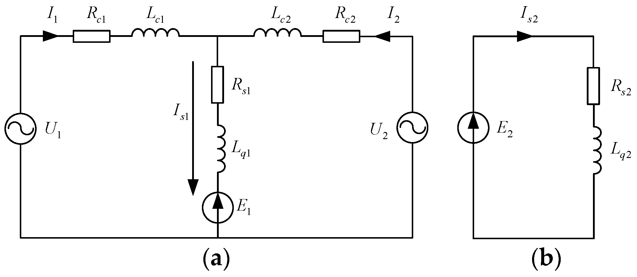
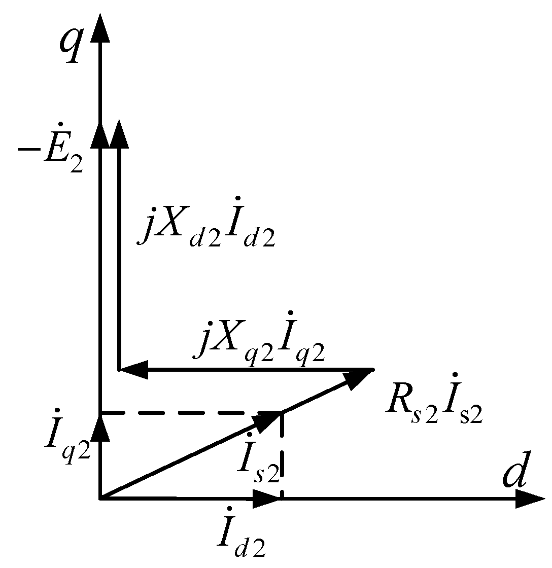
3. Mathematical Model of Three-Phase Short-Circuit Fault of LLSM

The process of the Maglev train passing through the short-circuit fault segment is shown in Figure 3. When the train has not yet reached the short-circuit point, such as in position 1, the LLSM works in the normal motor state. At this point, the train has reached the short-circuit point, such as in position 2, covering both the normal section and the fault section. The LLSM on the left side of the short-circuit point is in the normal section, which works as a motor to generate traction thrust. The LLSM on the right side of the short-circuit point is in the fault section, which works as a three-phase short-circuit generator to generate braking force. The magnitude of the braking force primarily depends on the length of the train covering the fault section. When the train has completely left the normal section, such as in position 3, the LLSM is working in the generator state. The train is subjected to a braking force, the magnitude of which depends primarily on the speed of the train. When the train has reached the next normal stator section, such as in position 4, the LLSM in the fault section still works as a generator to generate the braking force, while the LLSM in the next normal section works as a motor to generate thrust. The train starts to accelerate again.
The LLSM works normally when the train is in position 1. At this time, the voltage equation of the armature winding can be expressed as:
U ˙ s = R s I ˙ s + j X d I ˙ d + j X q I ˙ q + E ˙ 0
where U s is the phase voltage, R s is the winding resistance before the short-circuit point, ( X d ,   X q )   are the d-axis and q-axis reactance of the winding before the short-circuit point, ( I d ,   I q ) are the d-axis and q-axis component of LLSM stator current, I s is the phase current and E 0 is the phase back EMF.
When the train is in position 2, the LLSM is divided into two parts. One part is connected to the converter, which is equivalent to a long stator segment with a shortened length. The other part is equivalent to a three-phase short-circuit linear generator. The single-phase equivalent circuits of the two parts are shown in Figure 4a,b, respectively; where R c 1 ,   L c 1 ,   R c 2 ,   L c 2 are the resistance and inductance of the left- and right-side feeder cables of the normal working part, R s 1 ,   L q 1 and R s 2 ,   L q 2 are the winding resistance and q-axis inductance of the normal part and the fault part, respectively; E 1 and E 2 are the back EMF of the two parts, respectively. The magnitude of the back EMF depends on the running speed of the train, the length of the motor and the magnitude of the excitation current. The part connected to the power supply continues to work normally, as shown in Figure 4a. It is assumed that the motor current I s 1 is the same as before. The part between the fault point and the three-phase center point is the three-phase short-circuit section, as shown in Figure 4b. This part can be regarded as a generator, and the current in the motor is generated by the back EMF.
As is shown in Figure 4b, the phase voltage is U s = 0 in this part of the LLSM. The voltage equation of the armature winding can be expressed as:
E ˙ 2 = R s 2 I ˙ s 2 + j X d 2 I ˙ d 2 + j X q 2 I ˙ q 2
where ( X d 2 ,   X q 2 ) are the d-axis and q-axis reactance of the fault part winding, ( I d 2 ,   I q 2 ) are the d-axis and q-axis component of the fault part LLSM stator current, I s 2 is the fault part LLSM phase current.
The steady-state phasor diagram of this part of the LLSM is shown in Figure 5.
The current of LLSM after the fault can be obtained through the phasor diagram. The braking force generated by the LLSM after the fault can be calculated as follows:
F x = π τ [ ( L d 2 L q 2 ) i d 2 i q 2 + L m d i f i q 2 ]
where τ is the stator armature pole pitch, L d 2 and L q 2 are the d-axis inductance and q-axis inductance, i f is the converted excitation current.

4. Simulation of Three-Phase Short-Circuit Fault of LLSM

4.1. Simulation Model

Based on MATLAB/Simulink, the simulation model of the three-phase short-circuit fault segment of the high-speed Maglev train is established according to the mathematical model. The short process of the train passing through the fault segment is simulated and analyzed. The parameters of the LLSM and Maglev train used by Simulink model are shown in Table 1.

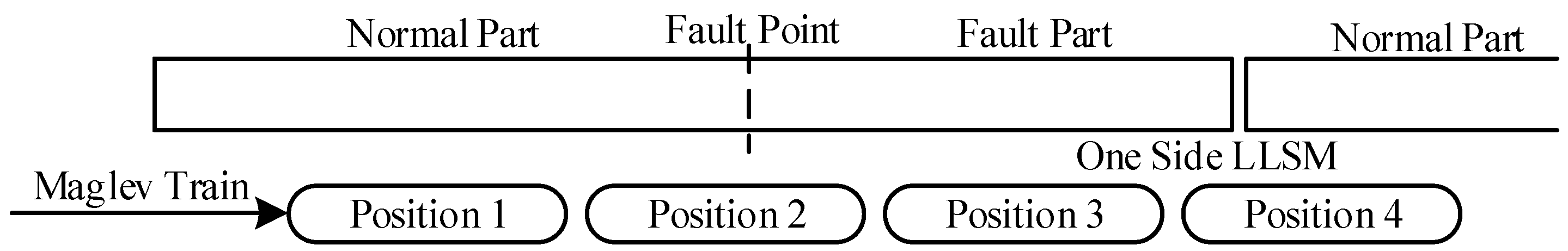
4.2. The Fault Operation Process

Assuming that the high-speed Maglev train is at a constant speed of 600 km/h before entering the fault segment and the stator current is 513 A, if the fault point is located at the starting point of the stator segment, the fault segment length is the length of the stator segment, which is 1200 m. During the process of the train, from passing the short-circuit point to entering the next normal stator segment, the force of one-side LLSM is shown in Figure 6, which is divided into traction force and braking force.
During the process of the train passing through the fault point, the length of the fault stator covered by the LLSM gradually increases, while the length of the normal stator covered by the LLSM gradually decreases. When the train completely enters the fault segment, the traction force drops to 0. On the contrary, the braking force gradually increases. As a result of the high running speed and high current frequency, the short-circuit stator segment is mainly reactance, and the resistance can be ignored. The reactance and the back EMF are proportional to the length of the fault segment, therefore, the braking force can reach a stable value. When the train leaves the fault segment and gradually enters the next normal stator segment, the traction force increases and the braking force decreases. After the train completely leaves the fault segment, the traction force returns to normal and the braking force drops to 0.
It can be seen from Figure 6 that when the train is completely in the fault stator segment, the braking force of the fault side motor is 4.6 kN and the acceleration of the train is −0.16 m/s2. The speed of the train during the whole process drops by 4.1 km/h. The acceleration-distance curve is shown in Figure 7.

4.3. Failure Performance of the LLSM at Different Speeds

Maintain the length of the fault section at 1200 m and change the running speed of the train before reaching the short-circuit point. The braking force of the fault side LLSM in the fault segment, at different speeds, is shown in Figure 8. The fault stator current at different speeds is close because both the back EMF and the reactance are proportional to the speed and the resistance can be ignored. However, the internal power factor angles are 81.6°, 85.8°, and 87.2°, respectively. Therefore, when the train runs faster, the q-axis current component and the braking force generated by the motor will be smaller.

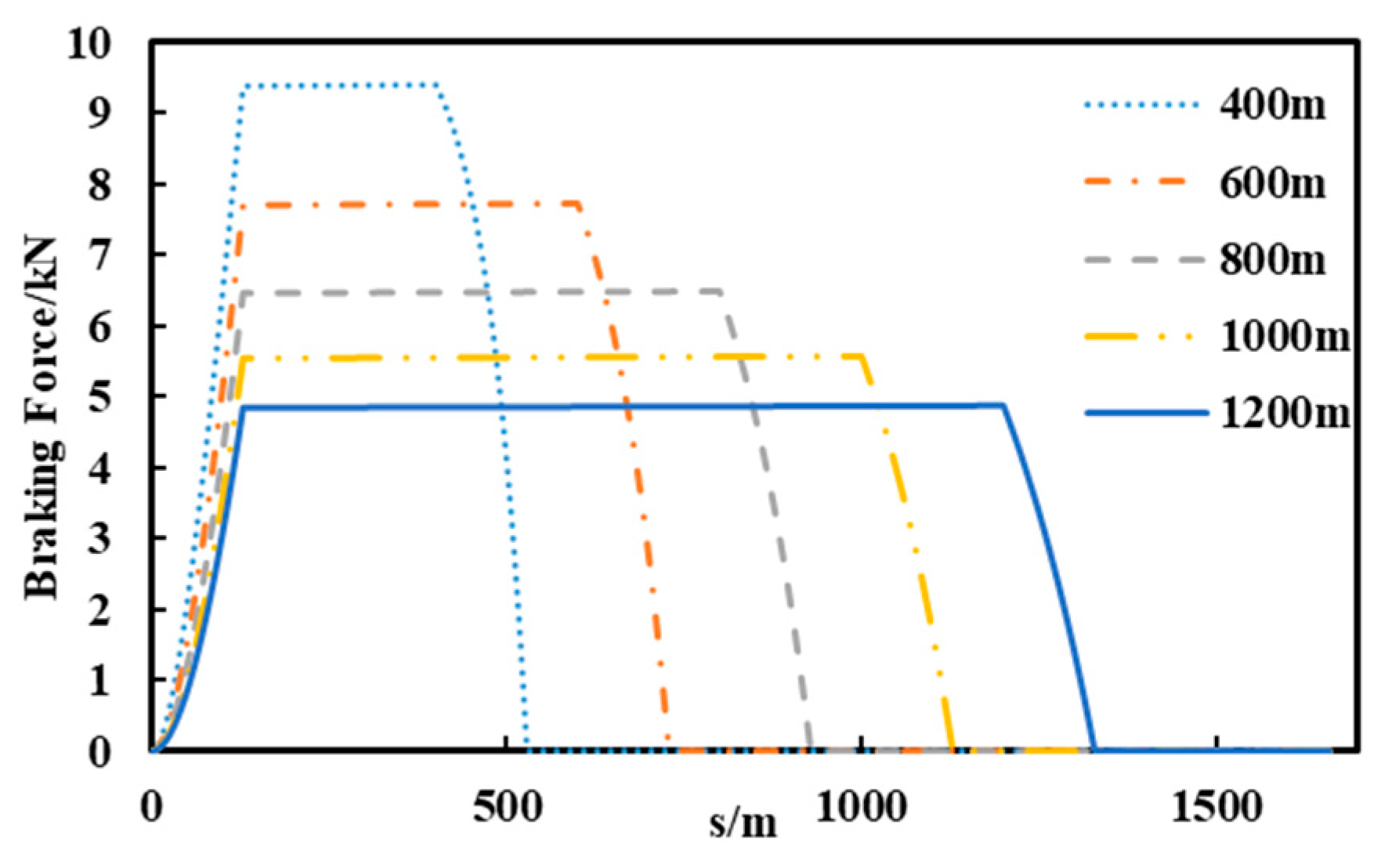
4.4. Failure Performance of the LLSM at Different Lengths of Fault Stator Segment

Maintain the running speed of the train at 600 km/h before reaching the short-circuit point and change the length of the fault stator segment. The braking force of the fault side LLSM is shown in Figure 9. The longer the fault segment length is, the greater the stator winding’s resistance and inductance are. The back EMF is determined by the length of the mover. In this case, the length of the mover remains unchanged. Therefore, the current generated in the stator and the braking force will be smaller as the length of the fault stator segment becomes longer.

5. Simulation of Three-Phase Short-Circuit Fault during Line Operation

5.1. Simulation Model

The above simulation is carried out for one long stator segment. The speed of the train when passing the fault point is assumed and the whole line operation is not considered. Therefore, the whole line operation needs to be simulated and analyzed.
The length of whole line is set to 50 km and the maximum capacity of the converter is 24 MVA. The simulation model of the whole line is built through MATLAB/Simulink. The power supply system adopts a three-step method [20]. The parameters of the LLSM and the power supply system are shown in Table 2.

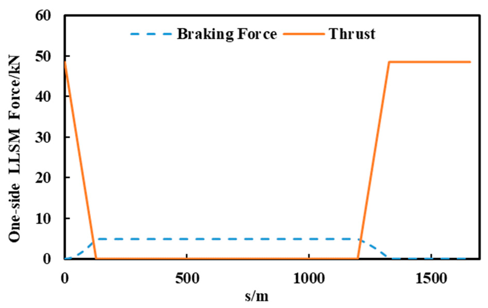
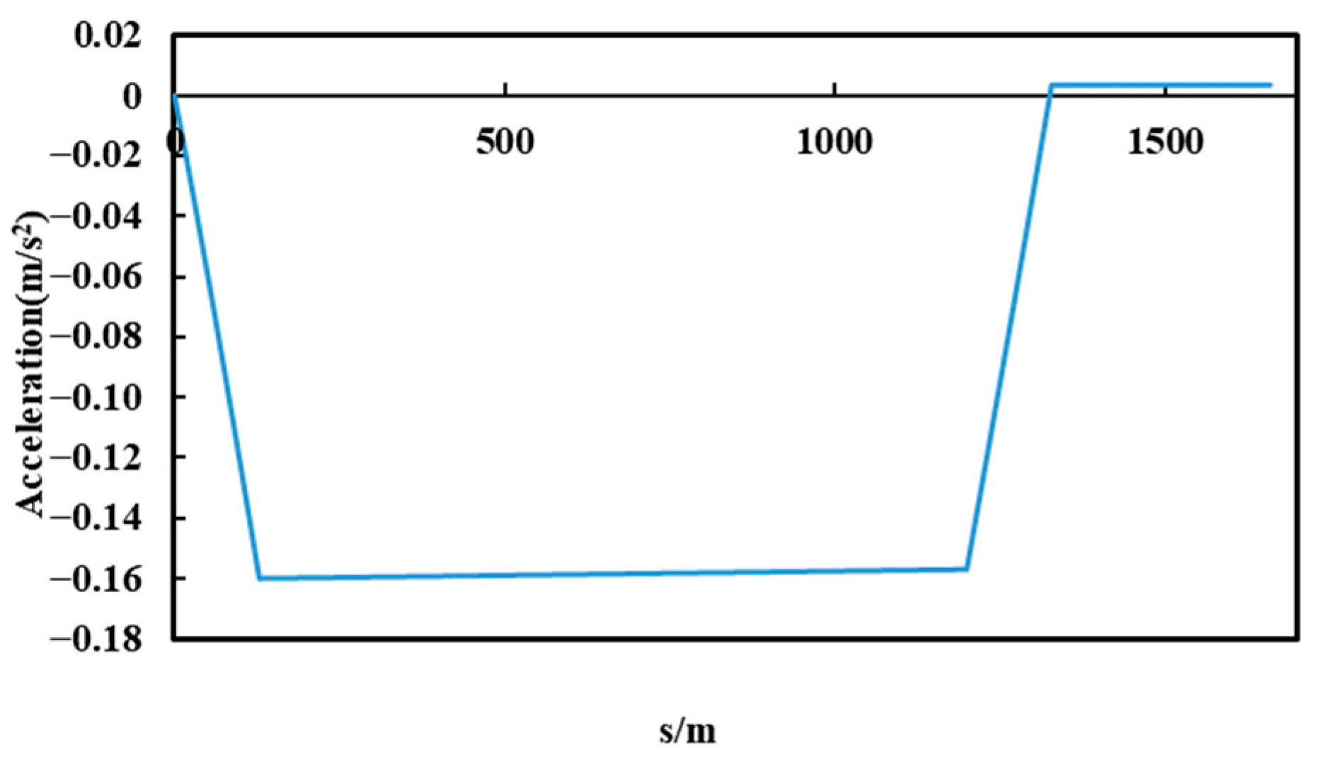
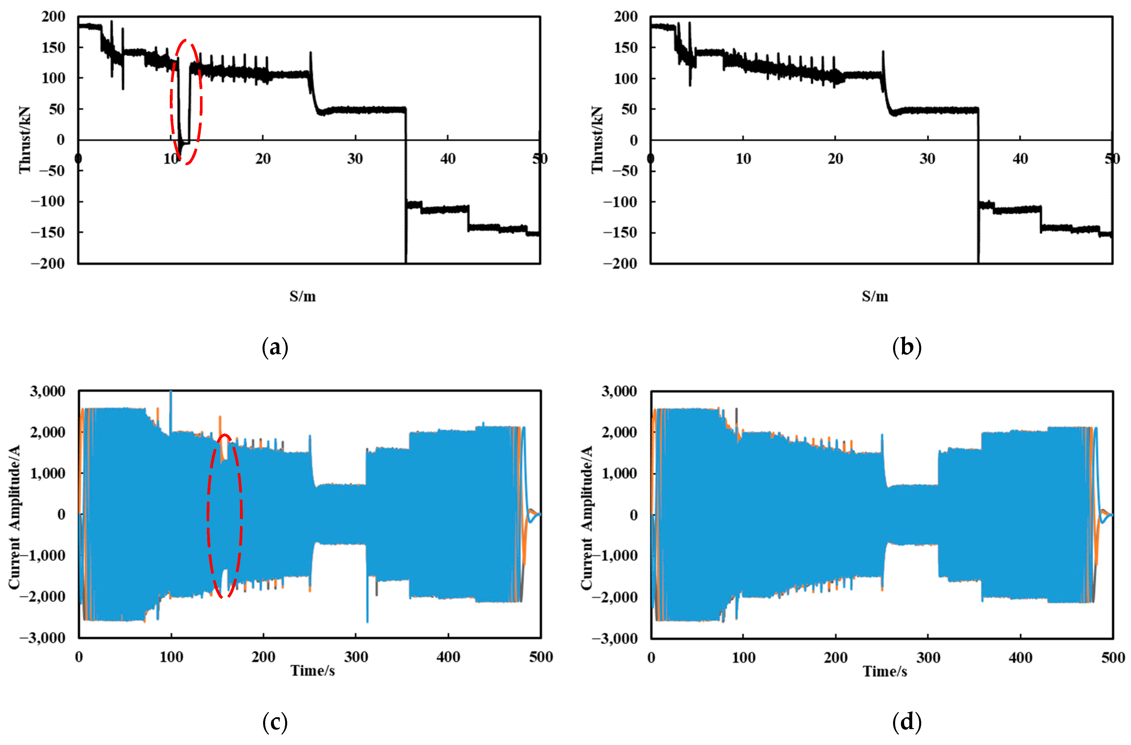
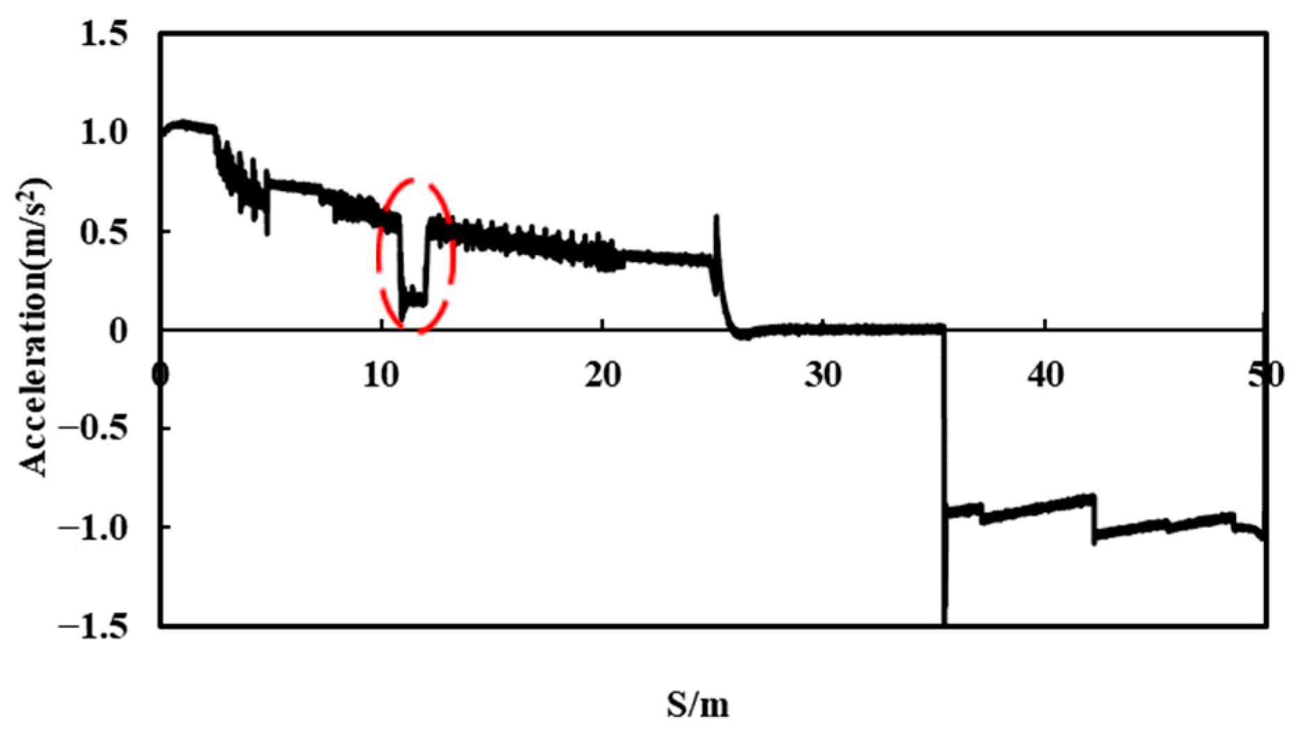
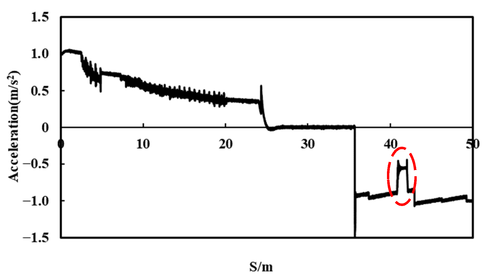
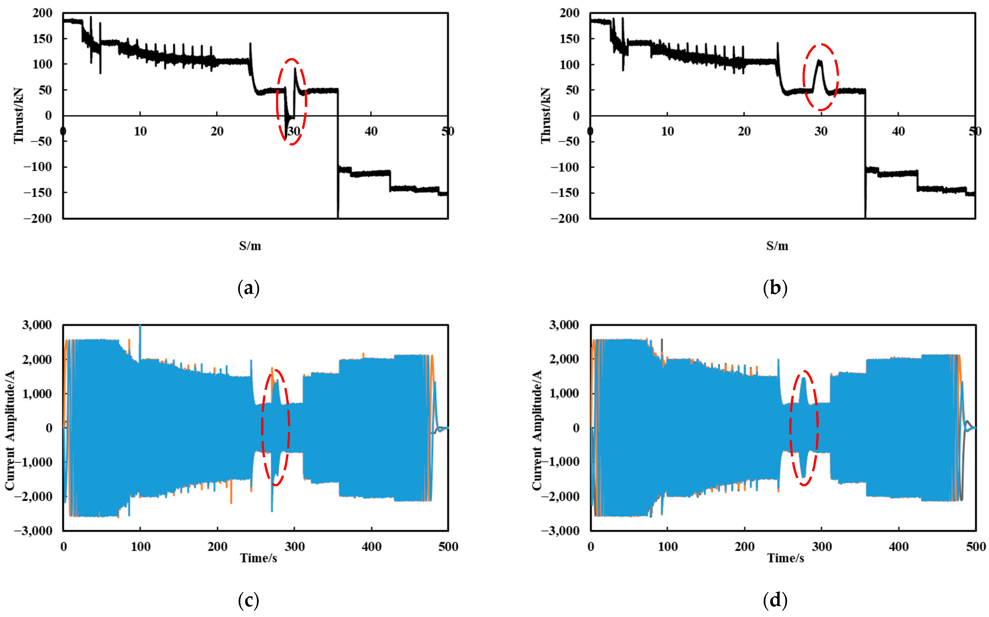
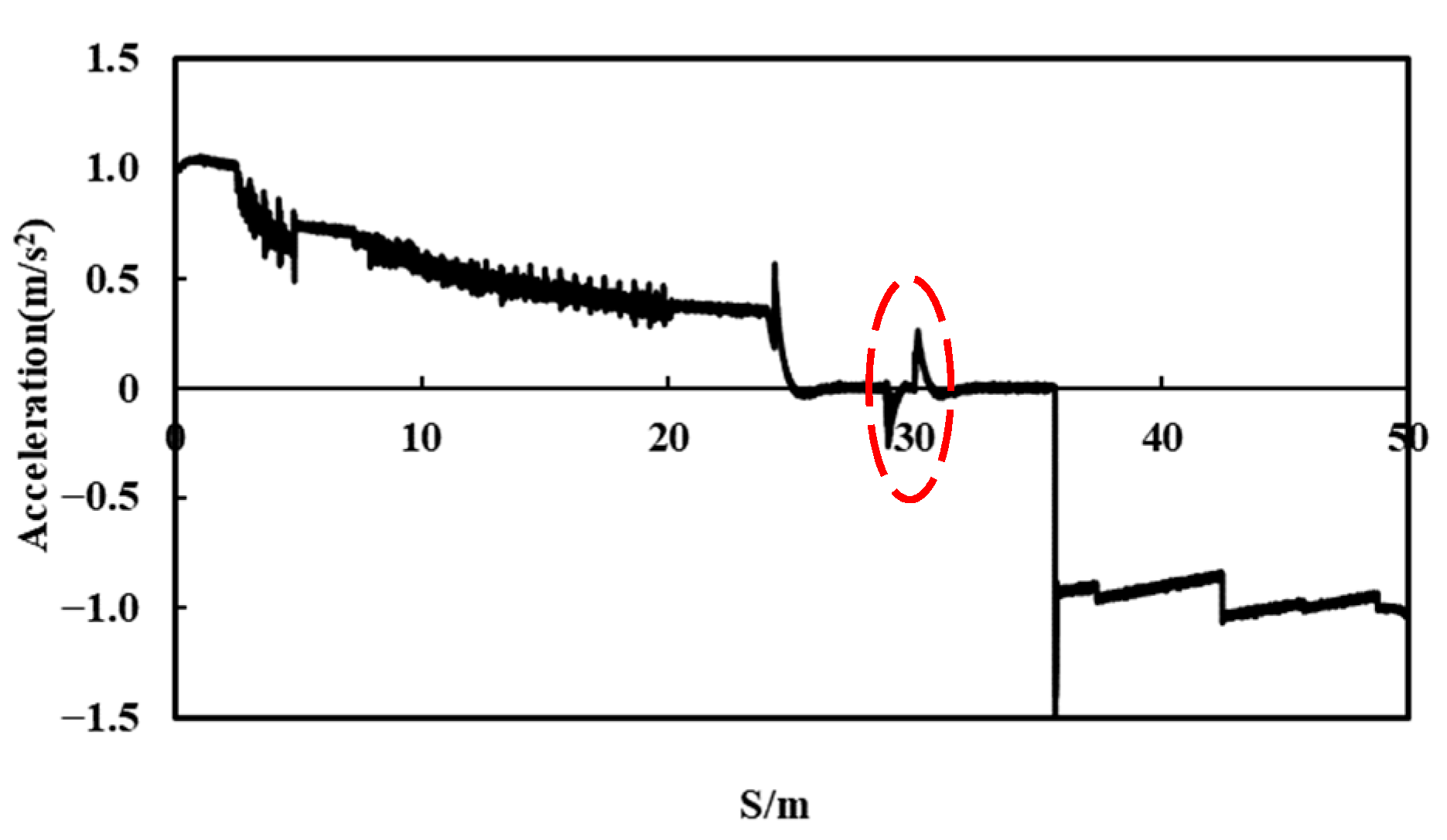
5.2. Fault during Acceleration or Deceleration Process

Assuming that a three-phase short-circuit fault occurs at the 10th segment in the left-side stator, of which the distance is 12 km, at this time, the train is still accelerating. The stator currents and forces of the LLSM in two sides during the whole process are shown in Figure 10.
When the train passes through the fault segment during the acceleration process, the left-side LLSM is subjected to a braking force of 5.8 kN as circled in Figure 10a. The right-side converter is in the maximum output state to enable it to provide a traction force of 124 kN. As circled in Figure 11, the acceleration decreases from 0.56 m/s2 to 0.17 m/s2 during the process. The acceleration can return to normal after the train leaves the fault segment and enters the next normal stator segment.
Assuming that a three-phase short-circuit fault occurs at the 35th segment in the left-side stator, of which the distance is 42 km, at this time, the train is decelerating. The stator currents and forces of the LLSM in two sides during the whole process are shown in Figure 12.
When the train passes through the fault segment during the deceleration process, the left-side LLSM is subjected to a braking force of 5.8 kN as circled in Figure 12a. The right-side converter is in the maximum output state, meaning it can provide a braking force of 110 kN. As circled in Figure 13, the deceleration decreases from 0.89 m/s2 to 0.54 m/s2 during the process. The deceleration can return to normal after the train leaves the fault segment and enters the next normal stator segment.

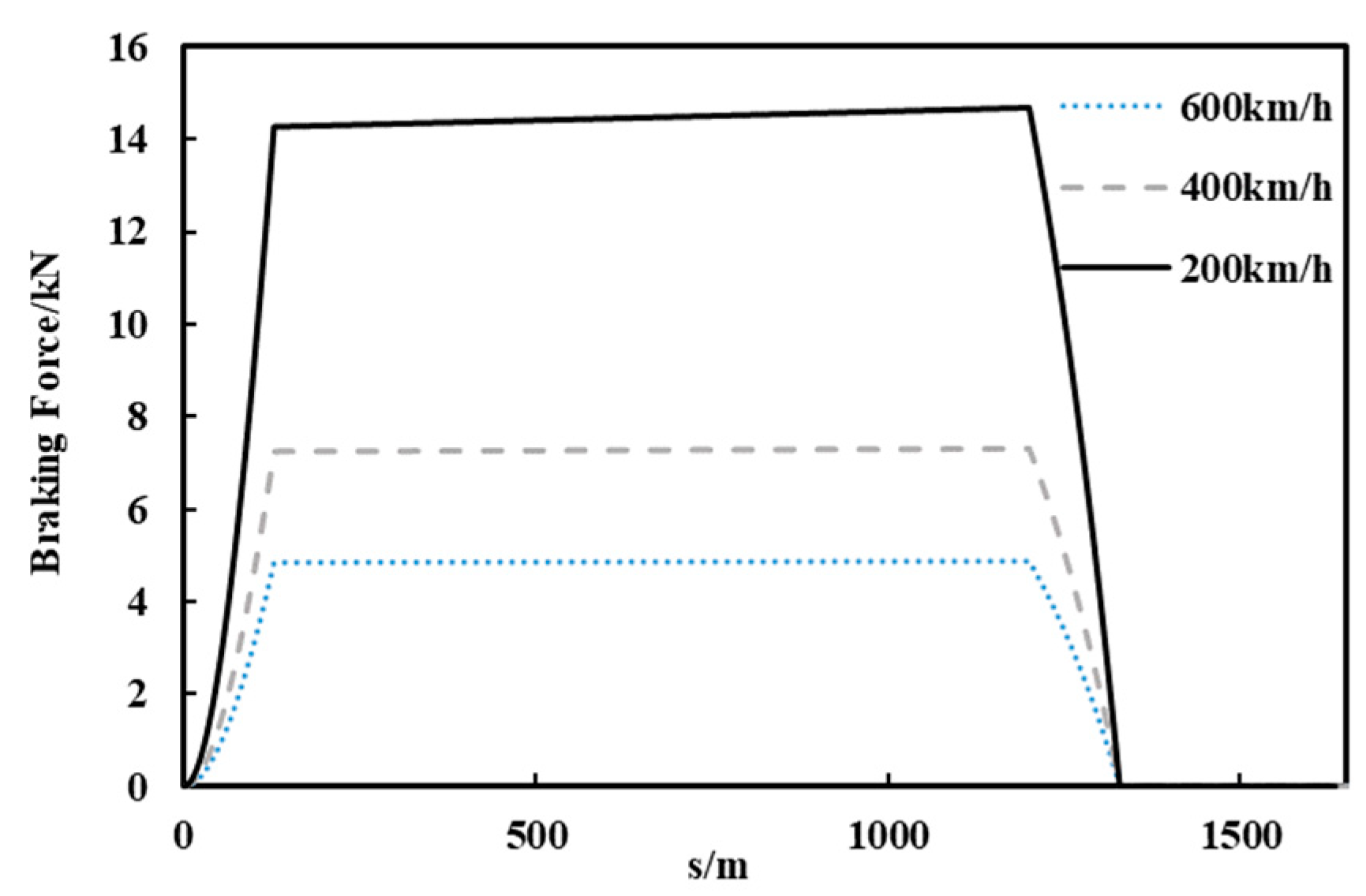
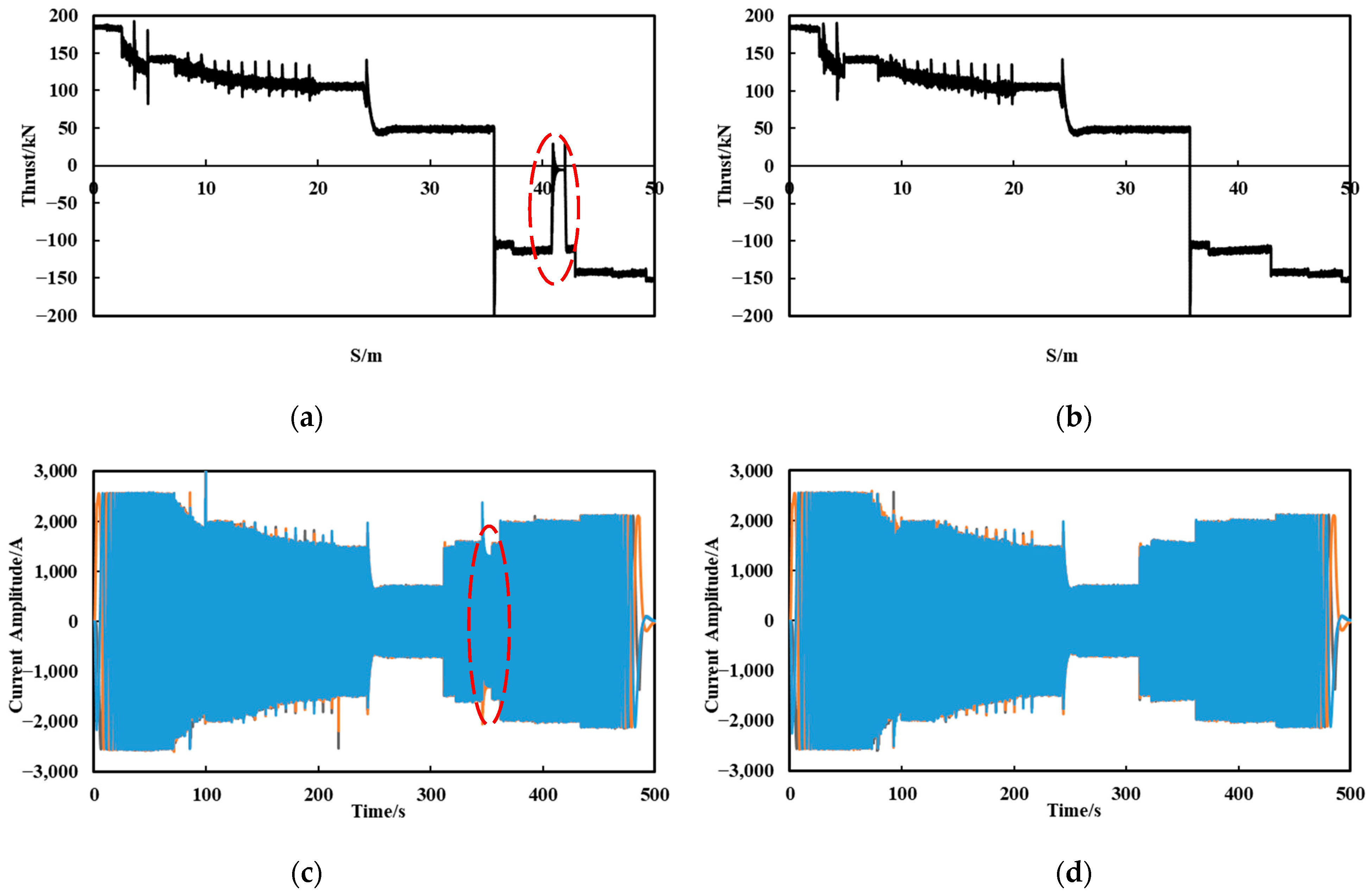
5.3. Fault during Constant Speed

Assuming that a three-phase short-circuit fault occurs at the 25th segment in the left side stator, of which the distance is 30 km, the train already operates at constant speed of 600 km/h at this time. The stator currents and forces of the LLSM at two sides during the entire fault process are shown in Figure 14.
When the train operates at 600 km/h, the LLSM on each side of the train can provide a traction force of 48.5 kN. The capacity of the converter is not at the maximum value, and thus can provide residual acceleration for the train. When the train enters the fault segment, the left-side LLSM generates a braking force of 4.6 kN, while the right-side LLSM can provide 102 kN traction force as circled in Figure 14a,b, which can compensate for the force loss of the fault side. Therefore, although the acceleration has some fluctuation during the fault segment as circled in Figure 15, it will soon return to 0. During the whole process, the acceleration of the train is shown in Figure 15.
Comparing the above simulation results in the acceleration, deceleration and constant speed stages, it is evident that the occurrence of a three-phase short-circuit fault in both acceleration and deceleration stage has a greater impact on the operation of the train. The converters on both sides are the maximum output during this stage. The normal side convert operates in maximum output state and could not produce extra current; the acceleration of the train is greatly reduced. When a failure occurs in the constant speed stage, the converters on both sides are not in the maximum output state. Although the braking force is generated on the fault side, the thrust on the other side can be twice to compensate for the thrust loss. Therefore, the total thrust remains unchanged and the fault has little effect on the running of the train.

6. Conclusions

This paper focuses on the three-phase short-circuit fault of a LLSM for the high-speed Maglev train. The mathematical model of the LLSM after the three-phase short-circuit fault is established. Under a double-end power supply mode, the operation performance of the LLSM at two sides is simulated and analyzed during whole line of 50 km. The simulation results will provide a reference for LLSM three-phase short-circuit fault analysis and fault diagnosis in high-speed Maglev trains. It is of great significance for improving the fault-tolerant control of the high-speed Maglev train to ensure the stability of train operation.

Author Contributions

Conceptualization, Q.L. and Y.L.; methodology, Y.L.; software, Y.L. and H.Y.; validation, Y.L. and H.Y.; formal analysis, Y.L.; investigation, H.Y.; resources, Q.L.; data curation, H.Y.; writing—original draft preparation, H.Y.; writing—review and editing, Y.L. and H.Y.; visualization, H.Y.; supervision, Y.L.; project administration, Q.L.; funding acquisition, Q.L. All authors have read and agreed to the published version of the manuscript.

Funding

This research was funded by National Natural Science Foundation of China under Grant NSFC52177061.

Data Availability Statement

Study did not report any data.

Conflicts of Interest

The authors declare no conflict of interest.

References

  1. Lee, H.-W.; Kim, K.-C.; Lee, J. Review of Maglev Train Technologies. IEEE Trans. Magn. 2006, 42, 1917–1925. [Google Scholar] [CrossRef]
  2. Luguang, Y. Progress of the Maglev Transportation in China. IEEE Trans. Appl. Supercond. 2006, 16, 1138–1141. [Google Scholar] [CrossRef]
  3. Luo, R.; Wu, J.; Wang, Z. Analysis and research on several faults of high speed maglev train long stator track. J. Railw. Sci. Eng. 2019, 16, 2658–2667. [Google Scholar] [CrossRef]
  4. Zhang, Y.; Wu, J.; Hong, X.; He, Y. Short-Circuit Fault Detection in Laminated Long Stators of High-Speed Maglev Track Based on Fractal Dimension. Measurement 2021, 176, 109177. [Google Scholar] [CrossRef]
  5. Zou, Z.; Zheng, M.; Lu, Q. Modeling and Simulation of Traction Power Supply System for High-Speed Maglev Train. WEVJ 2022, 13, 82. [Google Scholar] [CrossRef]
  6. Zhai, M.; Long, Z.; Li, X. Fault-Tolerant Control of Magnetic Levitation System Based on State Observer in High Speed Maglev Train. IEEE Access 2019, 7, 31624–31633. [Google Scholar] [CrossRef]
  7. Lu, Z.; Wang, W.; Tian, W. Fault-Tolerant Control for Five-Leg Two-Mover Permanent-Magnet Linear Motor Traction Systems with Open-Phase Fault. In Proceedings of the 2021 13th International Symposium on Linear Drives for Industry Applications (LDIA), Wuhan, China, 1–3 July 2021; pp. 1–4. [Google Scholar]
  8. Lin, Y.; Wang, X.; Qin, F.; Jin, Y.; Lu, D.; Ni, F. A New Concept Structure of the Propulsion System for a Medium Speed Maglev System—Simulation and Analysis. In Proceedings of the 2019 12th International Symposium on Linear Drives for Industry Applications (LDIA), Neuchatel, Switzerland, 1–3 July 2019; pp. 1–4. [Google Scholar]
  9. Hao, L.; Huang, Z.; Dong, F.; Qiu, D.; Shen, B.; Jin, Z. Study on Electrodynamic Suspension System with High-Temperature Superconducting Magnets for a High-Speed Maglev Train. IEEE Trans. Appl. Supercond. 2019, 29, 3600105. [Google Scholar] [CrossRef]
  10. Li, L.; Zhang, J.; Lu, Q. Investigation of Electromagnetic Coupling Field of Traction and Levitation Systems in High Speed Maglev Train. In Proceedings of the 2019 22nd International Conference on Electrical Machines and Systems (ICEMS), Harbin, China, 11–14 August 2019; pp. 1–6. [Google Scholar]
  11. Liu, J.; Ge, Q.; Wang, X. Traction-system research for high-speed maglev based on double-end supply. Adv. Technol. Electr. Eng. Energy 2015, 34, 16–21. [Google Scholar]
  12. Tseng, W.-T. Thrust Reduction of Magnetic Levitation Vehicle Driven by Long Stator Linear Synchronous Motor. Math. Probl. Eng. 2013, 2013, 850615. [Google Scholar] [CrossRef] [Green Version]
  13. Lin, Y.; Ying, L.; Qin, F.; Geng, Q.; WAng, X.; Xiaohua, W. The Simulation and Analysis for a New Concept of the Stator Power Supply Mode of a Medium Speed Maglev System. Transp. Syst. Technol. 2018, 4, 225–233. [Google Scholar] [CrossRef]
  14. Tan, Q.; Wei, R.; Wang, X.; Ge, Q. Traction-System Research Based on Different Proportion of Current in Double-End Supply for High-Speed Maglev. In Proceedings of the 2017 20th International Conference on Electrical Machines and Systems (ICEMS), Sydney, NSW, Australia, 11–14 August 2017; pp. 1–5. [Google Scholar]
  15. Cui, D.; Wei, R.; Liu, J.; Ge, Q. Linear Synchronous Motor Drive System Based on Proportion Resonant Current Controller in Maglev Transportation. In Proceedings of the 2014 17th International Conference on Electrical Machines and Systems (ICEMS), Hangzhou, China, 22–25 October 2014; pp. 1289–1292. [Google Scholar]
  16. Xu, L.; Wei, R.; Ge, Q.; Wang, X.; Li, Y. Hardware-in-Loop Simulation of Linear Synchronous Motor Based on Three-Level Converter. In Proceedings of the 2013 International Conference on Electrical Machines and Systems (ICEMS), Busan, Korea, 26–29 October 2013; pp. 1944–1947. [Google Scholar]
  17. Ikeda, H.; Kaga, S.; Osada, Y.; Ito, K.; Mugiya, Y.; Tutumi, K. Development of Power Supply System for Yamanashi Maglev Test Line. In Proceedings of the Power Conversion Conference—PCC ’97, Nagaoka, Japan, 6 August 1997; Volume 1, pp. 37–41. [Google Scholar]
  18. Lee, J.; Jo, J.; Han, Y.; Lee, C. Development of LSM Control System for Super Speed Maglev. In Proceedings of the 2013 13th International Conference on Control, Automation and Systems (ICCAS 2013), Gwangju, Korea, 20–23 October 2013; pp. 466–469. [Google Scholar]
  19. Liu, Y.; Fan, K.; Ouyang, Q. Intelligent Traction Control Method Based on Model Predictive Fuzzy PID Control and Online Optimization for Permanent Magnetic Maglev Trains. IEEE Access 2021, 9, 29032–29046. [Google Scholar] [CrossRef]
  20. Zhang, Y.; Qing, G.; Zhang, Z.; Li, J.; Chen, H. Calculation and Simulation of Propulsion Power Supply System for High-Speed Maglev Train. In Proceedings of the 2020 IEEE Vehicle Power and Propulsion Conference (VPPC), Gijon, Spain, 18 November–16 December 2020; pp. 1–5. [Google Scholar]
Figure 1. Double-end power supply mode.
Wevj 13 00216 g001
Figure 2. Control strategy of LLSM in this paper.
Wevj 13 00216 g002
Figure 3. The process of Maglev train passing through three-phase short-circuit fault point.
Wevj 13 00216 g003
Figure 4. Single-phase equivalent circuit of the LLSM with three-phase short-circuit fault: (a) normal part; (b) fault part.
Wevj 13 00216 g004
Figure 5. Phasor diagram of LLSM with three-phase short-circuit fault.
Wevj 13 00216 g005
Figure 6. The force of one-side LLSM during the process.
Wevj 13 00216 g006
Figure 7. Acceleration of the Maglev train during the fault process.
Wevj 13 00216 g007
Figure 8. The braking force of one-side LLSM at different speeds.
Wevj 13 00216 g008
Figure 9. The braking force of one-side LLSM at different lengths of fault stator segment.
Wevj 13 00216 g009
Figure 10. The current and thrust force of LLSM at two sides when the fault occurs during acceleration process: (a) thrust of the fault side LLSM; (b) thrust of the normal side LLSM; (c) current of the fault side stator segment; (d) current of the normal side stator segment.
Wevj 13 00216 g010
Figure 11. The whole acceleration of the train when the fault occurs during acceleration process.
Wevj 13 00216 g011
Figure 12. The current and thrust force of LLSM at two sides when the fault occurs during deceleration process: (a) thrust of the fault side LLSM; (b) thrust of the normal side LLSM; (c) current of the fault side stator segment; (d) current of the normal side stator segment.
Wevj 13 00216 g012
Figure 13. The whole acceleration of the train when the fault occurs during deceleration process.
Wevj 13 00216 g013
Figure 14. The current and thrust force of LLSM at two sides when the fault occurs during constant speed: (a) thrust of the fault side LLSM; (b) thrust of the normal side LLSM; (c) current of the fault side stator segment; (d) current of the normal side stator segment.
Wevj 13 00216 g014
Figure 15. The whole acceleration of the train when the fault occurs during constant speed.
Wevj 13 00216 g015
Table 1. The parameters of the LLSM and Maglev train in Simulink model.
ParametersValue
Pitch Length (m)0.258
Back EMF Coefficient (V/(km/h)/km)74.84
One-side Motor Thrust Coefficient (kN/A/km)0.735
Train Length (m)128.5
Stator Segment Length (m)1200
Train Mass (t)330
Table 2. The parameters of the LLSM and power supply system.
ParametersValue
Feeder Cable Resistance ( Ω /km)0.05833
Feeder Cable Inductance (H/km)0.000071
Stator Resistance ( Ω / km )0.23
D-axis Inductance (mH)3
Q-axis Inductance (mH)2.8
Converter Maximum Capacity (MVA)24
DC Bus Voltage (V)4400
Publisher’s Note: MDPI stays neutral with regard to jurisdictional claims in published maps and institutional affiliations.

