
An ICN-Based IPFS High-Availability Architecture

Abstract
:1. Introduction
- An ICN-based IPFS high-availability architecture (IBIHA) is proposed, introducing the concept of enhanced nodes and information management tables, and analyzing the advantages that can be brought.
- A traffic-based influential node selection algorithm for complex networks is designed to solve the deployment problem of augmented nodes.
- We simulate the implementation of the IBIHA architecture and the traditional IPFS network in NS3 and compare their performance gap in terms of resolution and delivery. We validate the effectiveness of the proposed algorithm on the example network and the real network dataset, respectively.
2. Related Work
2.1. Availability of IPFS
2.1.1. Data Availability
- Data is not available due to nodes going offline.
- Data retrieval information is not updated in a timely manner, resulting in the inaccessibility of the latest data.
2.1.2. Link Availability
2.1.3. Node Availability
2.2. Information-Centric Networking
3. Design Overview
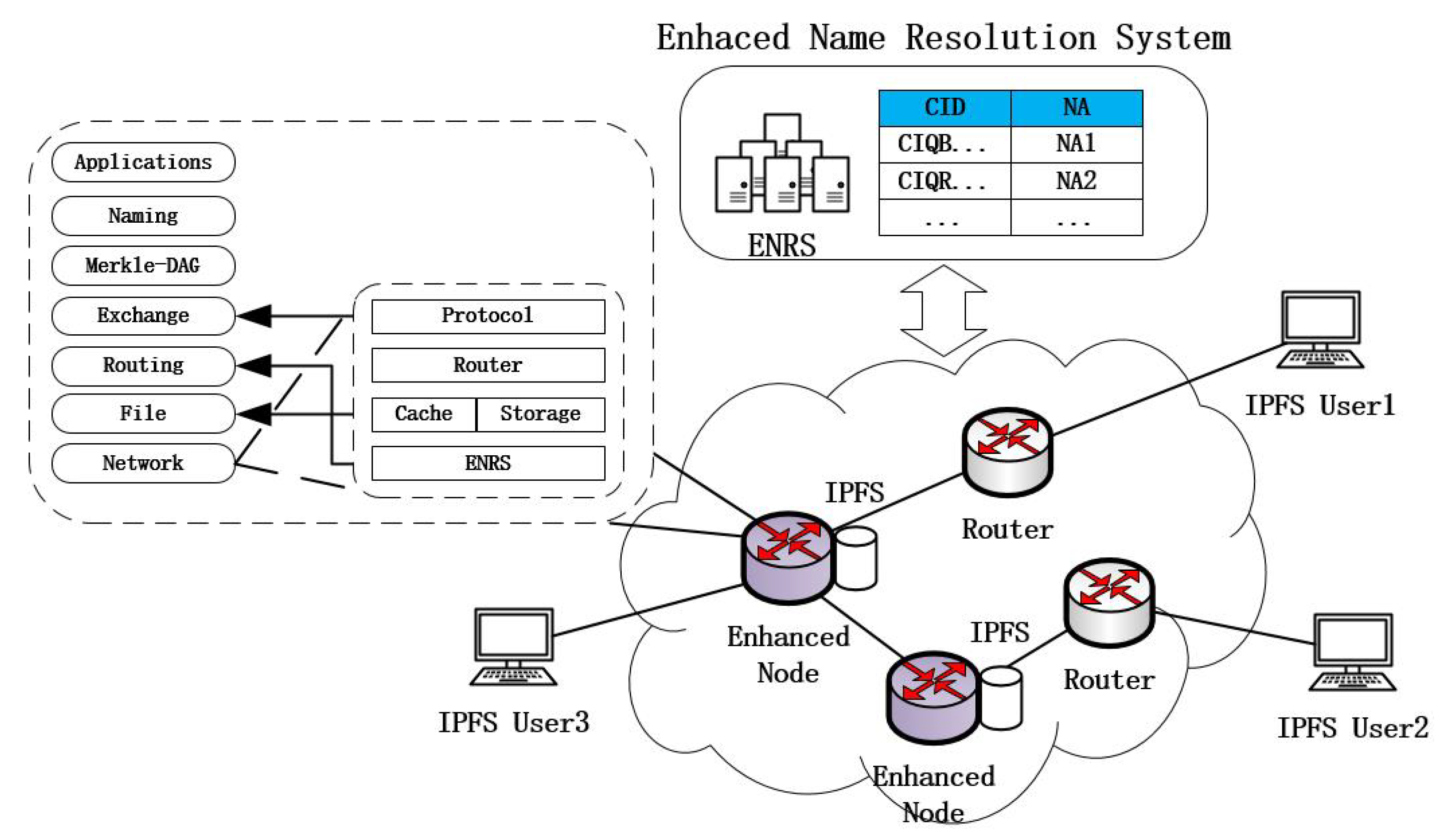
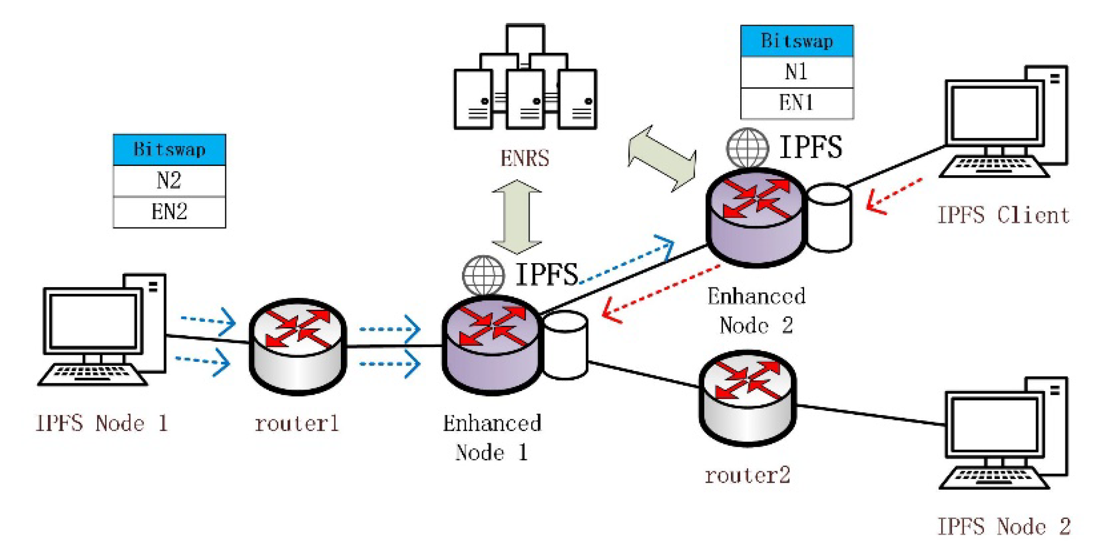
3.1. IBIHA Overview
- IPFS Node: These are many IPFS network nodes that initiate data requests from the edge of the network and enable data retrieval and data exchange through the DHT and Bitswap mechanisms.
- Routing Node: completes only the data forwarding function.
- Enhanced Node: ICN node for deploying IPFS applications. It is the peer node for all IPFS application nodes in the IPFS network, and it is also the router node in the transmission process.
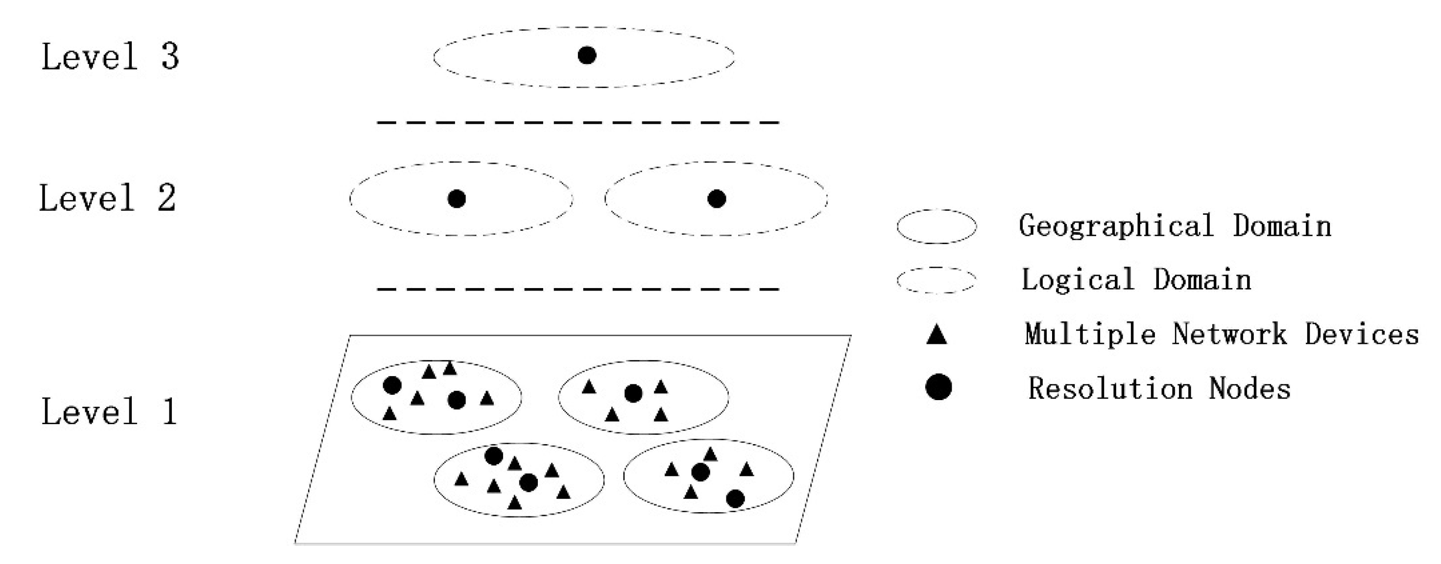
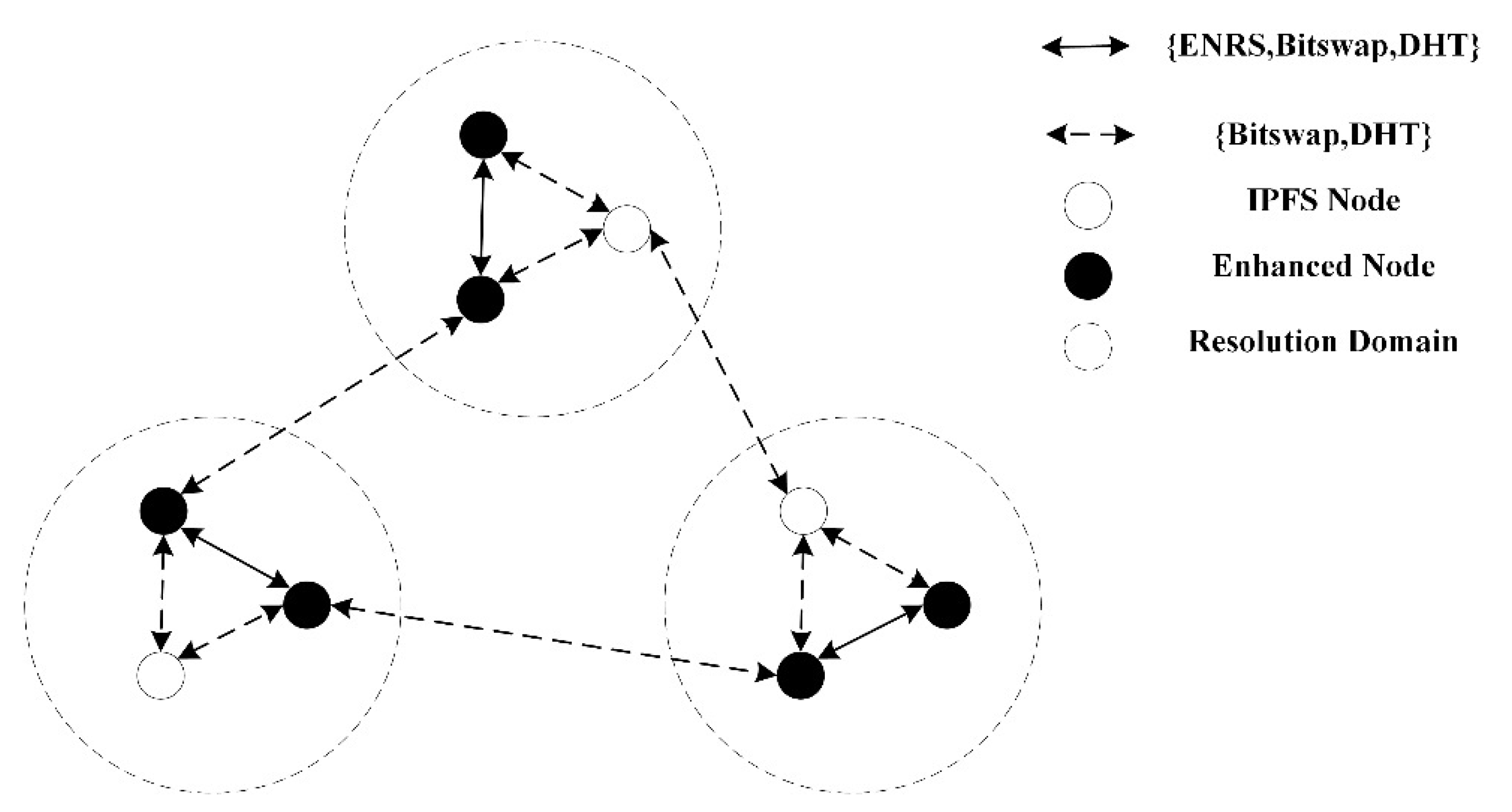
3.1.1. Resolution Mechanism
3.1.2. Data Distribution
- Nodes are high-performance network nodes with stable online rates;
- Nodes support ENRS, which can meet users’ needs for nearby access;
- The network composed of nodes can provide caching and storage services, reducing the deployment costs of content service providers.
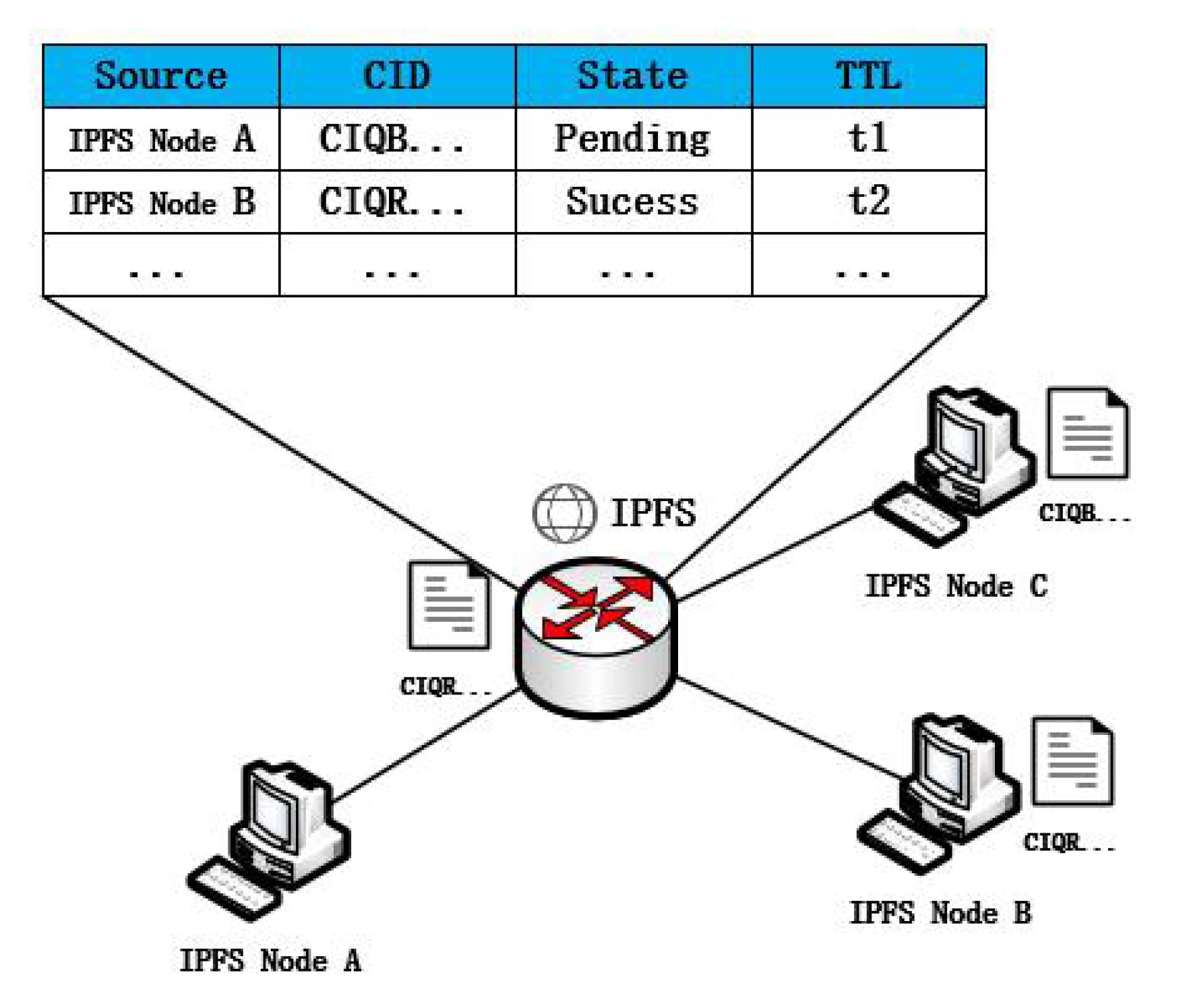
3.1.3. Information Management Table
3.2. Enhanced Node Performance Analysis
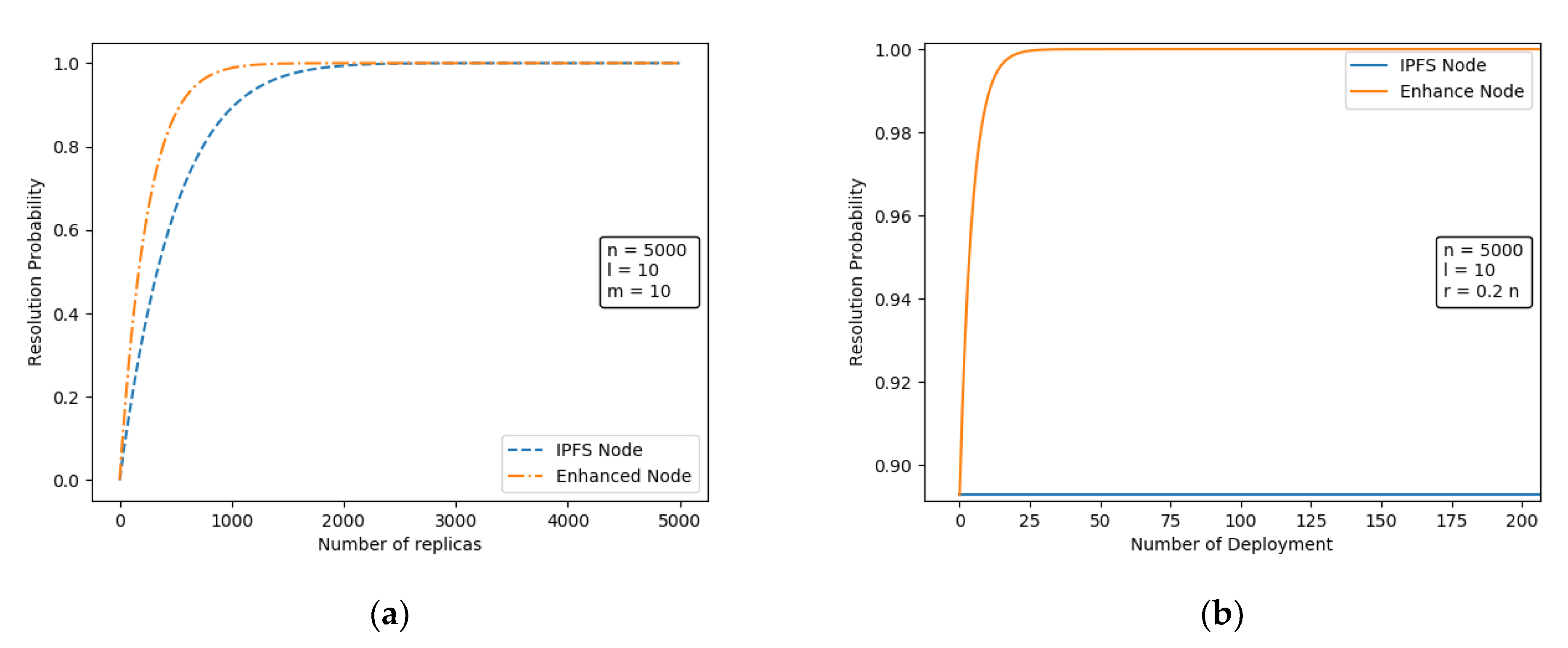
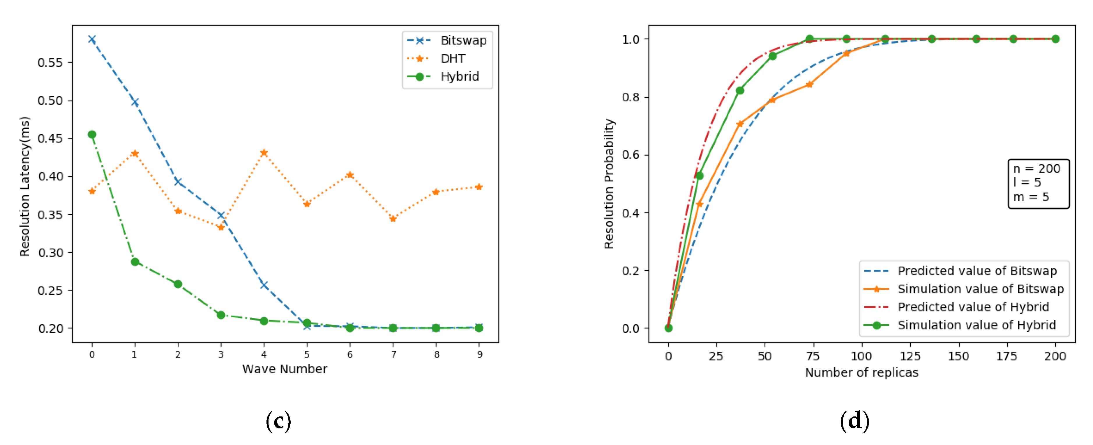
3.2.1. Resolution Performance Analysis
3.2.2. Distribution Performance Analysis
4. Enhanced Node Selection Algorithm
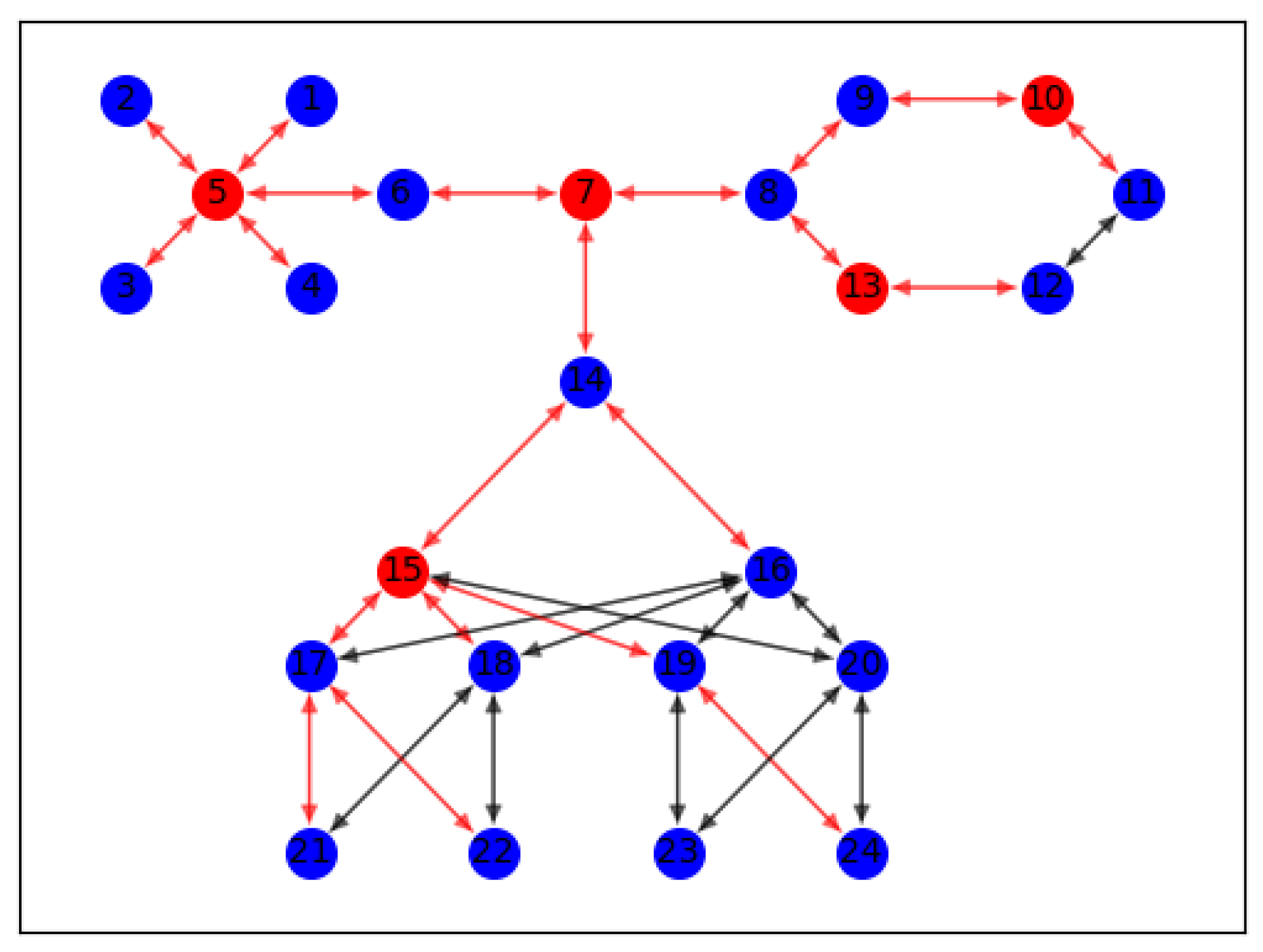
4.1. Analysis of Influential Nodes in Complex Networks
4.2. High-Influence Node Selection Algorithm Based on Node Traffic
| Algorithm 1. PwRank |
| Input: A network , and the number of nodes , and resolve probability |
| Output: A set including influential nodes. |
| 1: function Updata(, , + 1, ) |
| 2: ifthen |
| 3: returnNull |
| 4: end if |
| 5: for in do |
| 6: Updata(, , + 1, ) |
| 7: |
| 8: end for |
| 9: returnNull |
| 10: end function |
| 11: //PwRank main function |
| 12: |
| 13: |
| 14: for in do |
| 15: for in do |
| 16: |
| 17: |
| 18: end for |
| 19: end for |
| 20: while < do |
| 21: forindo |
| 22: |
| 23: |
| 24: end for |
| 25: for in do |
| 26: |
| 27: end for |
| 28: add to , where |
| 29: |
| 30: Updata(, , , ) |
| 31: end while |
| 32: return |
5. Simulation Results and Analysis
5.1. Application Layer Performance Comparison
5.1.1. Setting of Experimental Environment
5.1.2. Performance Analysis
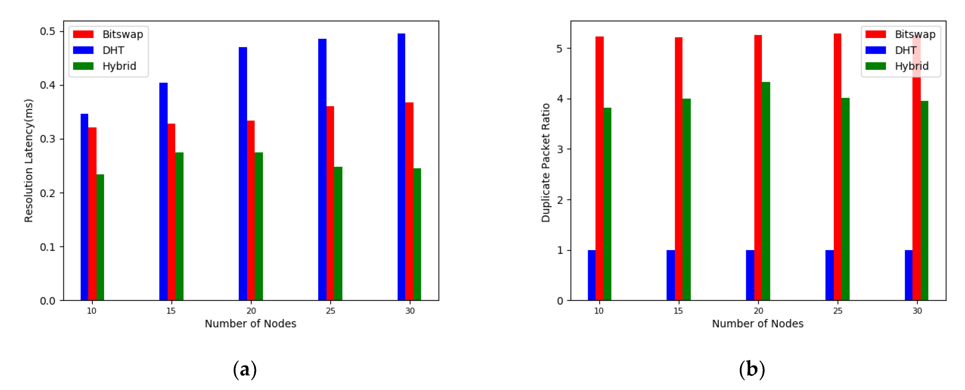
5.2. Network Layer Performance Comparison
5.2.1. Experimental Setup
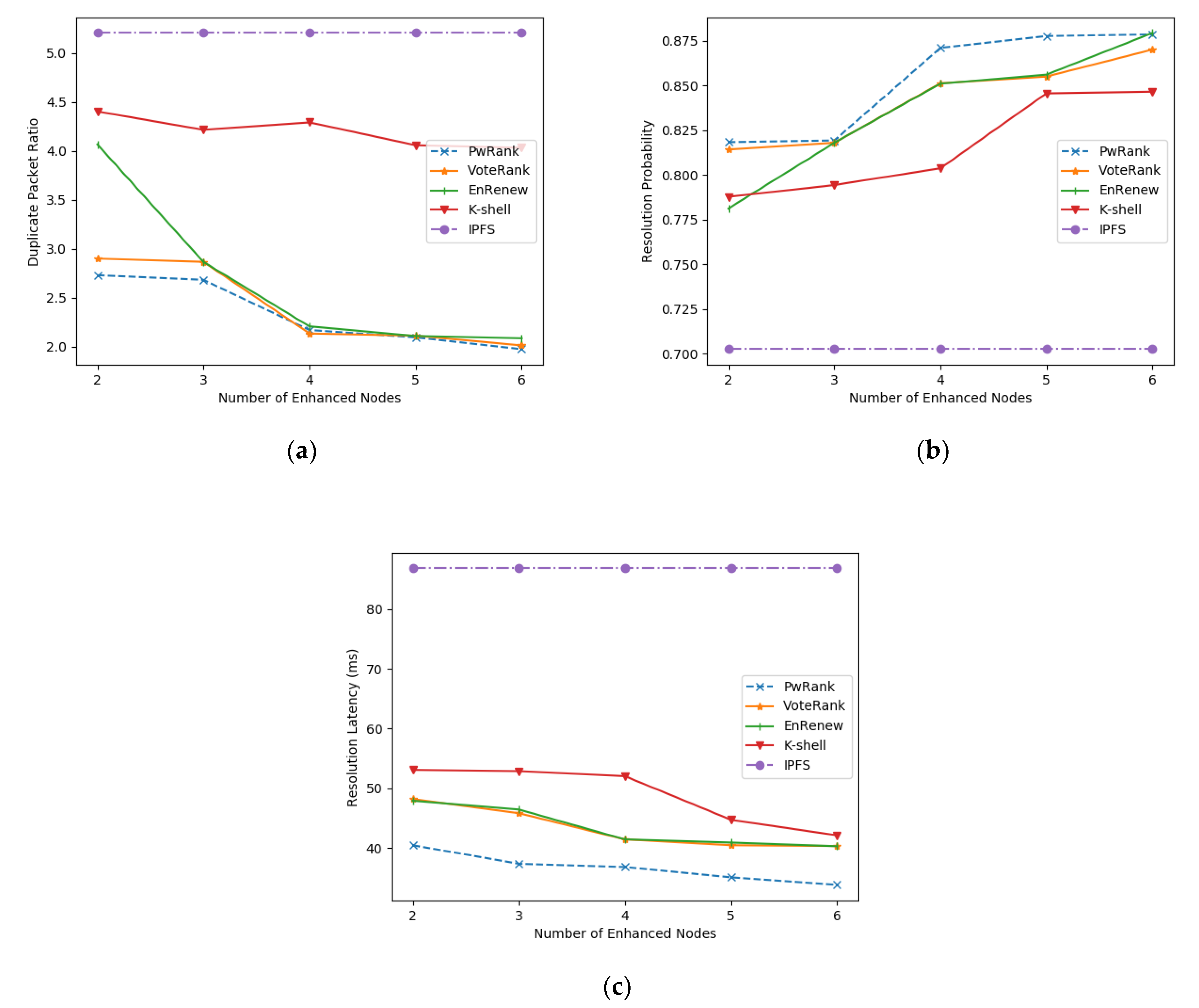
5.2.2. Performance Analysis
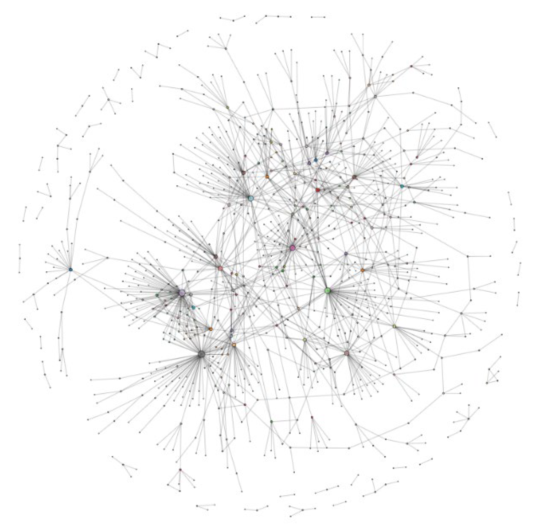
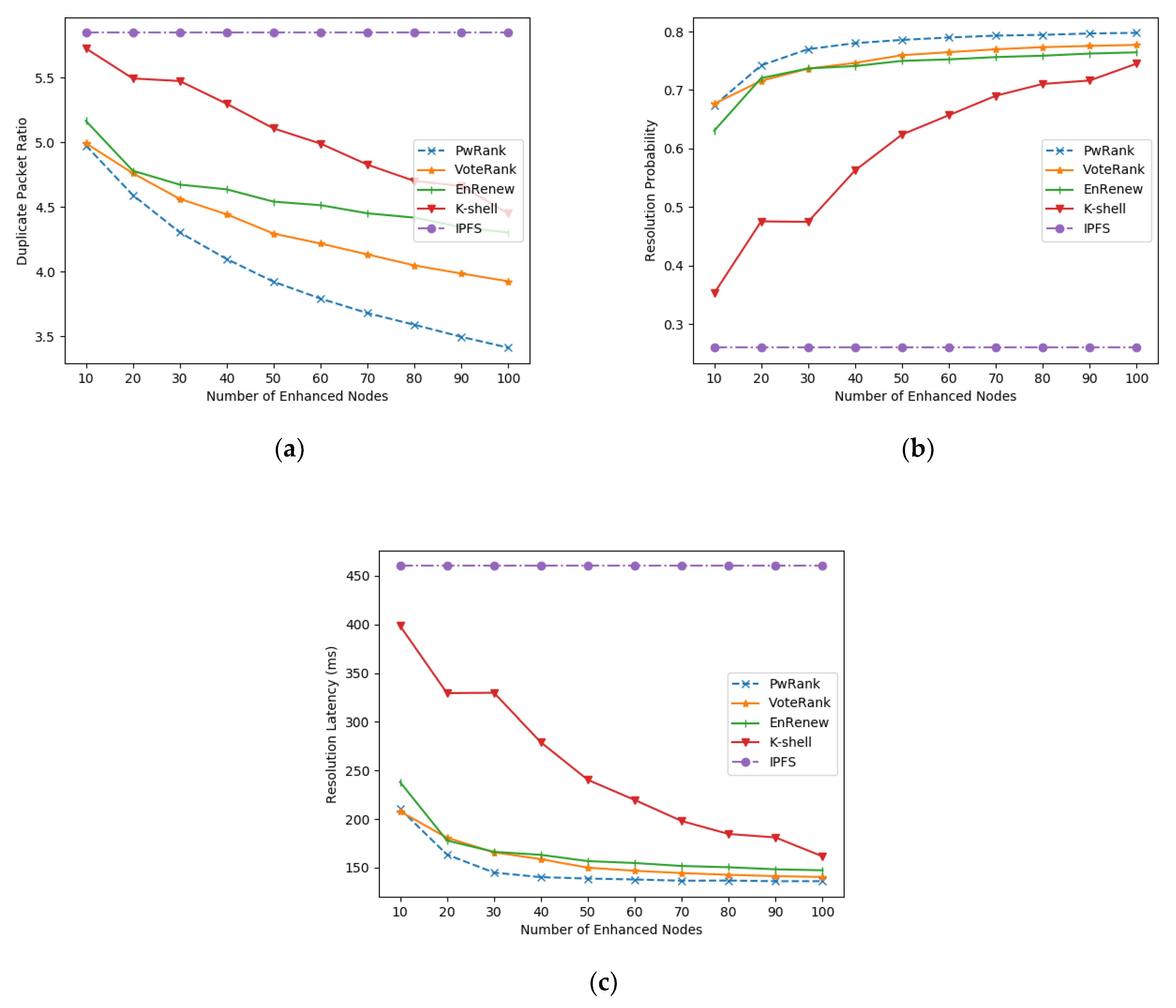
5.2.3. Real Network Performance Analysis
6. Conclusions
Author Contributions
Funding
Institutional Review Board Statement
Informed Consent Statement
Data Availability Statement
Acknowledgments
Conflicts of Interest
References
- Bieri, C. An Overview into the InterPlanetary File System (IPFS): Use Cases, Advantages, and Drawbacks. In Communication Systems XIV; University of Zurich: Zurich, Switzerland, 2021; p. 78. [Google Scholar]
- Haßlinger, G.; Hartleb, F. Content delivery and caching from a network provider’s perspective. Comput. Netw. 2011, 55, 3991–4006. [Google Scholar] [CrossRef]
- Ascigil, O.; Reñé, S.; Król, M.; Pavlou, G.; Zhang, L.; Hasegawa, T.; Koizumi, Y.; Kita, K. Towards peer-to-peer content retrieval markets: Enhancing IPFS with ICN. In Proceedings of the 6th ACM Conference on Information-Centric Networking 2019, Macao, China, 24–26 September 2019; pp. 78–88. [Google Scholar]
- Ghaznavi, M.; Jalalpour, E.; Salahuddin, M.A.; Boutaba, R.; Migault, D.; Preda, S. Content Delivery Network Security: A Survey. IEEE Commun. Surv. Tutor. 2021, 23, 2166–2190. [Google Scholar] [CrossRef]
- Nakamoto, S.; Bitcoin, A. A Peer-to-Peer Electronic Cash System. Bitcoin. 2008. Available online: https://bitcoin.org/bitcoin.Pdf (accessed on 25 January 2022).
- Buterin, V. Ethereum white paper. GitHub Repos. 2013, 1, 22–23. [Google Scholar]
- Benet, J. Ipfs-content addressed, versioned, p2p file system. arXiv 2014, arXiv:1407.3561. preprint. [Google Scholar]
- Alessi, M.; Camillo, A.; Giangreco, E.; Matera, M.; Pino, S.; Storelli, D. Make users own their data: A Decentralized Personal Data Store Prototype Based on Ethereum and Ipfs. In Proceedings of the 2018 3rd International Conference on Smart and Sustainable Technologies (SpliTech), Split, Croatia, 26–29 June 2018; IEEE: Piscataway, NJ, USA, 2018; pp. 1–7. [Google Scholar]
- Sun, J.; Yao, X.; Wang, S.; Wu, Y. Blockchain-based secure storage and access scheme for electronic medical records in IPFS. IEEE Access 2020, 8, 59389–59401. [Google Scholar] [CrossRef]
- Tenorio-Fornés, A.; Hassan, S.; Pavón, J. Open peer-to-peer systems over blockchain and ipfs: An agent oriented framework. In Proceedings of the 1st Workshop on Cryptocurrencies and Blockchains for Distributed Systems; Association for Computing Machinery: New York, NY, USA, 2018; pp. 19–24. [Google Scholar]
- Ye, H.; Park, S. Reliable vehicle data storage using blockchain and IPFS. Electronics 2021, 10, 1130. [Google Scholar] [CrossRef]
- Ortega, V.; Monserrat, J.F. Semantic Distributed Data for Vehicular Networks Using the Inter-Planetary File System. Sensors 2020, 20, 6404. [Google Scholar] [CrossRef] [PubMed]
- Muralidharan, S.; Ko, H. An InterPlanetary file system (IPFS) based IoT framework. In Proceedings of the 2019 IEEE International Conference on Consumer Electronics (ICCE), Las Vegas, NV, USA, 11–13 January 2019; IEEE: Piscataway, NJ, USA, 2019; pp. 1–2. [Google Scholar]
- Pappas, C.; Chatzopoulos, D.; Lalis, S.; Vavalis, M. Ipls: A framework for decentralized federated learning. In Proceedings of the 2021 IFIP Networking Conference (IFIP Networking), Espoo and Helsinki, Finland, 21–24 June 2021; IEEE: Piscataway, NJ, USA, 2021; pp. 1–6. [Google Scholar]
- Confais, B.; Lebre, A.; Parrein, B. An Object Store Service for a Fog/Edge Computing Infrastructure Based on Ipfs and a Scale-Out nas. In Proceedings of the IEEE 1st International Conference on Fog and Edge Computing (ICFEC), Madrid, Spain, 14–15 May 2017; IEEE: Piscataway, NJ, USA, 2017; pp. 41–50. [Google Scholar]
- Shen, J.; Li, Y.; Zhou, Y.; Wang, X. Understanding I/O performance of IPFS storage: A client’s perspective. In Proceedings of the 2019 IEEE/ACM 27th International Symposium on Quality of Service (IWQoS), Phoenix, AZ, USA, 24–25 June 2019; IEEE: Piscataway, NJ, USA, 2019; pp. 1–10. [Google Scholar]
- Abdullah Lajam, O.; Ahmed Helmy, T. Performance Evaluation of IPFS in Private Networks. In Proceedings of the 2021 4th International Conference on Data Storage and Data Engineering, Barcelona, Spain, 18–20 February 2021; pp. 77–84. [Google Scholar]
- Henningsen, S.; Florian, M.; Rust, S.; Scheuermann, B. Mapping the interplanetary filesystem. In Proceedings of the 2020 IFIP Networking Conference (Networking), Paris, France, 22–26 June 2020; IEEE: Piscataway, NJ, USA, 2020; pp. 289–297. [Google Scholar]
- On, G.; Schmitt, J.; Steinmetz, R. The Effectiveness of Realistic Replication Strategies on Quality of Availability for Peer-To-Peer Systems. In Proceedings of the Third International Conference on Peer-To-Peer Computing (P2P2003), Linkoping, Sweden, 1–3 September 2003; IEEE: Piscataway, NJ, USA, 2003; pp. 57–64. [Google Scholar]
- Spaho, E.; Barolli, A.; Xhafa, F.; Barolli, L. P2P Data Replication: Techniques and Applications. In Modeling and Processing for Next-Generation Big-Data Technologies; Springer International Publishing: Cham, Switzerland, 2015. [Google Scholar]
- Guidi, B.; Michienzi, A.; Ricci, L. Data persistence in decentralized social applications: The ipfs approach. In Proceedings of the 2021 IEEE 18th Annual Consumer Communications & Networking Conference (CCNC), Las Vegas, NV, USA, 9–12 January 2021; IEEE: Piscataway, NJ, USA, 2021; pp. 1–4. [Google Scholar]
- IPFS 2022. IPNS. Available online: https://docs.ipfs.io/concepts/ipns/ (accessed on 25 January 2022).
- IPFS 2022. Merkle-DAG. Available online: https://docs.ipfs.io/concepts/merkle-dag/ (accessed on 25 January 2022).
- Maymounkov, P.; Mazieres, D. Kademlia: A Peer-To-Peer Information System Based on the Xor Metric. In International Workshop on Peer-to-Peer Systems; Springer: Berlin/Heidelberg, Germany, 2002; pp. 53–65. [Google Scholar]
- Guidi, B.; Conti, M.; Passarella, A.; Ricci, L. Managing social contents in decentralized online social networks: A survey. Online Soc. Netw. Media 2018, 7, 12–29. [Google Scholar] [CrossRef]
- De la Rocha, A.; Dias, D.; Psaras, Y. Accelerating Content Routing with Bitswap: A Multi-Path File Transfer Protocol in IPFS and Filecoin. 2021. Available online: https://research.protocol.ai/publications/accelerating-content-routing-with-bitswap-a-multi-path-file-transfer-protocol-in-ipfs-and-filecoin/ (accessed on 25 January 2022).
- Doan, T.V.; Bajpai, V.; Psaras, Y.; Ott, J. Towards Decentralised Cloud Storage with IPFS: Opportunities, Challenges, and Future Directions. arXiv 2022, arXiv:2202.06315. preprint. [Google Scholar]
- Chen, Y.; Li, H.; Li, K.; Zhang, J. An improved P2P file system scheme based on IPFS and Blockchain. In Proceedings of the 2017 IEEE International Conference on Big Data (Big Data), Boston, MA, USA, 11–14 December 2017; IEEE: Piscataway, NJ, USA, 2017; pp. 2652–2657. [Google Scholar]
- IPFS 2022. IPFS Cluster. Available online: https://cluster.ipfs.io/ (accessed on 25 January 2022).
- Shapiro, M.; Preguiça, N.; Baquero, C.; Zawirski, M. Conflict-free replicated data types. In Symposium on Self-Stabilizing Systems; Springer: Berlin/Heidelberg, Germany, 2011; pp. 386–400. [Google Scholar]
- Ongaro, D.; Ousterhout, J. In Search of an Understandable Consensus Algorithm. In Proceedings of the 2014 USENIX Annual Technical Conference (Usenix ATC 14), Philadelphia, PA, USA, 19–20 June 2014; pp. 305–319. [Google Scholar]
- Zhang, L.; Afanasyev, A.; Burke, J.; Jacobson, V.; Claffy, K.C.; Crowley, P.; Papadopoulos, C.; Wang, L.; Zhang, B. Named data networking. ACM SIGCOMM Comput. Commun. Rev. 2014, 44, 66–73. [Google Scholar] [CrossRef]
- Jacobson, V.; Smetters, D.K.; Thornton, J.D.; Plass, M.F.; Briggs, N.H.; Braynard, R.L. Networking named content. In Proceedings of the 5th International Conference on Emerging Networking Experiments and Technologies, Rome, Italy, 1–4 December 2009; pp. 1–12. [Google Scholar]
- Raychaudhuri, D.; Nagaraja, K.; Venkataramani, A. Mobilityfirst: A robust and trustworthy mobility-centric architecture for the future internet. ACM SIGMOBILE Mob. Comput. Commun. Rev. 2012, 16, 2–13. [Google Scholar] [CrossRef]
- Koponen, T.; Chawla, M.; Chun, B.G.; Ermolinskiy, A.; Kim, K.H.; Shenker, S.; Stoica, I. A data-oriented (and beyond) network architecture. In Proceedings of the 2007 Conference on Applications, Technologies, Architectures, and Protocols for Computer Communications, New York, NY, USA, 27–31 August 2007; pp. 181–192. [Google Scholar]
- Wang, J.; Chen, G.; You, J.; Sun, P. SEANet: Architecture and Technologies of an On-site, Elastic, Autonomous Network. J. Netw. New Media 2020, 9, 1–8. [Google Scholar]
- Dannewitz, C.; D’Ambrosio, M.; Vercellone, V. Hierarchical DHT-based name resolution for information-centric networks. Comput. Commun. 2013, 36, 736–749. [Google Scholar] [CrossRef]
- Liao, Y.; Sheng, Y.; Wang, J. A deterministic latency name resolution framework using network partitioning for 5G-ICN integration. Int. J. Innov. Comput. Inf. Control 2019, 15, 1865–1880. [Google Scholar]
- Song, Y.; Ni, H.; Zhu, X. An enhanced replica selection approach based on distance constraint in ICN. Electronics 2021, 10, 490. [Google Scholar] [CrossRef]
- Adamic, L.A.; Huberman, B.A. Zipf’s law and the Internet. Glottometrics 2002, 3, 143–150. [Google Scholar]
- Zhang, J.X.; Chen, D.B.; Dong, Q.; Zhao, Z.D. Identifying a set of influential spreaders in complex networks. Sci. Rep. 2016, 6, 1–10. [Google Scholar] [CrossRef] [PubMed]
- Guo, C.; Yang, L.; Chen, X.; Chen, D.; Gao, H.; Ma, J. Influential nodes identification in complex networks via information entropy. Entropy 2020, 22, 242. [Google Scholar] [CrossRef] [PubMed] [Green Version]
- Sun, H.-L.; Chen, D.-B.; He, J.-L.; Ch’Ng, E. A voting approach to uncover multiple influential spreaders on weighted networks. Phys. A Stat. Mech. Its Appl. 2019, 519, 303–312. [Google Scholar] [CrossRef]
- Kitsak, M.; Gallos, L.; Havlin, S.; Liljeros, F.; Muchnik, L.; Stanley, H.E.; Makse, H.A. Identification of influential spreaders in complex networks. Nat. Phys. 2010, 6, 888–893. [Google Scholar] [CrossRef] [Green Version]
- Rossi, R.; Ahmed, N. The network data repository with interactive graph analytics and visualization. In Proceedings of the Twenty-Ninth AAAI Conference on Artificial Intelligence 2015, Austin, TX, USA, 25–30 January 2015. [Google Scholar]


Publisher’s Note: MDPI stays neutral with regard to jurisdictional claims in published maps and institutional affiliations. |
© 2022 by the authors. Licensee MDPI, Basel, Switzerland. This article is an open access article distributed under the terms and conditions of the Creative Commons Attribution (CC BY) license (https://creativecommons.org/licenses/by/4.0/).
Share and Cite
Zeng, R.; You, J.; Li, Y.; Han, R. An ICN-Based IPFS High-Availability Architecture. Future Internet 2022, 14, 122. https://doi.org/10.3390/fi14050122
Zeng R, You J, Li Y, Han R. An ICN-Based IPFS High-Availability Architecture. Future Internet. 2022; 14(5):122. https://doi.org/10.3390/fi14050122
Chicago/Turabian StyleZeng, Ruibin, Jiali You, Yang Li, and Rui Han. 2022. "An ICN-Based IPFS High-Availability Architecture" Future Internet 14, no. 5: 122. https://doi.org/10.3390/fi14050122