Article

A Survey of Wi-Fi 6: Technologies, Advances, and Challenges

by
Erfan Mozaffariahrar
1,*,
Fabrice Theoleyre
2 and
Michael Menth
1
1
Chair of Communication Networks, University of Tuebingen, 72074 Tuebingen, Germany
2
ICube Laboratory, CNRS/University of Strasbourg, Pole API, 67081 Strasbourg, France
*
Author to whom correspondence should be addressed.
Future Internet 2022, 14(10), 293; https://doi.org/10.3390/fi14100293
Submission received: 1 September 2022 / Revised: 26 September 2022 / Accepted: 4 October 2022 / Published: 14 October 2022
(This article belongs to the Special Issue 5G Wireless Communication Networks)

Abstract

:
Wi-Fi is a popular wireless technology and is continuously extended to keep pace with requirements such as high throughput, real-time communication, dense networks, or resource and energy efficiency. The IEEE 802.11ax standard, also known as Wi-Fi 6, promises to provide data rates of up to almost 10 Gb/s, lower energy consumption, and higher reliability. Its capabilities go far beyond Wi-Fi 5 (802.11ac) and novel technical concepts have been introduced for this purpose. As such, the Wi-Fi 6 standard includes Multi-User Orthogonal Frequency Division Multiple Access (MU OFDMA), Multi-User Multiple-Input Multiple-Output (MU MIMO), new mechanisms for Spatial Reuse (SR), new mechanisms for power saving, higher-order modulation, and additional minor improvements. In this paper, we provide a survey of Wi-Fi 6. Initially, we provide a compact technological summary of Wi-Fi 5 and its predecessors. Then, we discuss the potential application domains of Wi-Fi 6, which are enabled through its novel features. Subsequently, we explain these features and review the related works in these areas. Finally, performance evaluation tools for Wi-Fi 6 and future roadmaps are discussed.

1. Introduction

Wireless traffic will significantly grow in the next few years. Cisco expects 71% mobile connectivity by 2023 [1]. The prime use cases of Wireless Local Area Networks (WLANs) are industrial automation with the motion flexibility of actuators, sensors, controllers, mobile users, dense networks including a large number of users, healthcare for patient monitoring and diagnosis, etc. [2]. Dense networks have a high density of users and access points, generating a large volume of interference [3]. They require efficient spatial frequency reuse.
The IEEE 802.11 standard fulfills these demands (in the literature, IEEE 802.11 and Wi-Fi are used interchangeably and we follow this convention). Wi-Fi is an unlicensed technology that focuses on the Physical (PHY) and Medium Access Control (MAC) layers. It is suitable for mobile and high-speed Internet access and is mainly deployed for enterprise and home networks. The number of public Wi-Fi hotspots is expected to reach 628 million in 2023 [1] as many infrastructures rely on Wi-Fi technology. The IEEE 802.11 standard introduced in 1997 was followed by major amendments (see Table 1): 802.11b, 802.11a, 802.11g, 802.11n, 802.11ac, 802.11ax, and 802.11be. They are considered generations and are also denoted as Wi-Fi 1 to Wi-Fi 7. The prevalent Wi-Fi, IEEE 802.11ac (Wi-Fi 5), meets neither the real-time and high-reliability demands of high-quality multimedia applications nor the energy efficiency of Internet of Things (IoT) networks. It cannot simultaneously support a large number of users with high Quality of Service (QoS) and suffers from inefficient power management.
The IEEE 802.11ax (Wi-Fi 6) task group started to investigate and design the next generation of WLAN appropriate for dense networks and real-time communications in 2014. The Wi-Fi 6 standard [4] was officially published in May 2021. The task group focused on providing a four times higher throughput per station while keeping the same power consumption as IEEE 802.11ac or improving it. Since this standard focuses on better spectrum efficiency, it is known as the high-efficiency standard. IEEE 802.11ax modifies both thePHY and MAC layers and introduces multiple features to enhance Wi-Fi users’ satisfaction. It achieves current expectations thanks to wider channels, MU OFDMA for channel access, uplink (UL) MU MIMO to improve capacity, SR for spectral efficiency, Target Wake Time (TWT) to manage power consumption, 1024 Quadrature Amplitude Modulation (QAM) to increase throughput, and other additional improvements [5]. Wi-Fi 6 operates on the 2.4, 5, and 6 GHz frequency bands. Together, these features lead to high data rates of up to 9.6 Gb/s.
The successor to the standard of Wi-Fi 6, IEEE 802.11be (Wi-Fi 7), is currently under study and targets ultra-high-throughput networks. However, it is only in its early stages and is not expected to be introduced before 2024. This survey serves as a basis for future improvements to Wi-Fi 7, making it a helpful research tool.

1.1. Contribution

In this paper, we consider publications about Wi-Fi 6 since 2015. To the best of our knowledge, the current paper is the first comprehensive literature review of IEEE 802.11ax based on the latest version of the standard.
There are already several tutorials describing novel features of Wi-Fi 6, which are listed in Table 2. Several papers present Wi-Fi 6 based on the early stages of the standardization [6,7,8] and are no longer up to date. Other tutorials focus on specific features such as resource allocation [9] or the MAC layer [10]. The most complete tutorial on Wi-Fi 6 is the one by Khorov et al. [11] with a focus on spatial reuse and random Orthogonal Frequency Division Multiple Access (OFDMA). In Section 2 and Section 3, we provide a detailed description of Wi-Fi 6 for the benefit of non-expert readers, which may be skipped by expert readers familiar with Wi-Fi 6.
In this article, we present a detailed survey of the studies of Wi-Fi 6. We identified the following surveys that have been published in this field (Table 3):
  • Wilhelmi [12] summarized the related works for spatial reuse in Wi-Fi 6;
  • Nurchis [13] focused on energy efficiency for low-power devices;
  • Masri [14] focused on scheduling and resource allocation;
  • Qu [15] presented a novel simulator for next-generation wireless networks and identified a few contributions to the field.
According to Table 2 and Table 3, each of these tutorials and surveys has only a few references in common with our paper. Therefore, our paper covers a large number of references that were not considered by other tutorial and review papers. Moreover, none of these surveys focus on modulation techniques and MU MIMO. Although OFDMA is investigated in [14], our survey is more comprehensive with more than 70 references in this field. In addition, we explore other topics in more detail than the other surveys.
The ambition of the current paper is a comprehensive survey of all the features of Wi-Fi 6. Its target and level of explanation focus on the networking aspect of the enhancements rather than on the signal processing field so it is of most interest to researchers in networking. In each section, it focuses on a specific feature of Wi-Fi 6 to survey the corresponding related works. Figure 1 visualizes the categorizations of the related works by feature and facilitates a fast lookup of the relevant references.
The main contributions of this paper are the following:
  • It explains the main features of Wi-Fi 6 based on the latest released standard. Thereby, it describes the improvements and differences compared to earlier Wi-Fi standards.
  • It provides a comprehensive review of the related works exploiting the new features.
  • It categorizes the related works regarding their objectives, which makes it easier for researchers to learn about the recent advances in Wi-Fi 6.
  • An overview of current evaluation tools and available hardware is compiled.

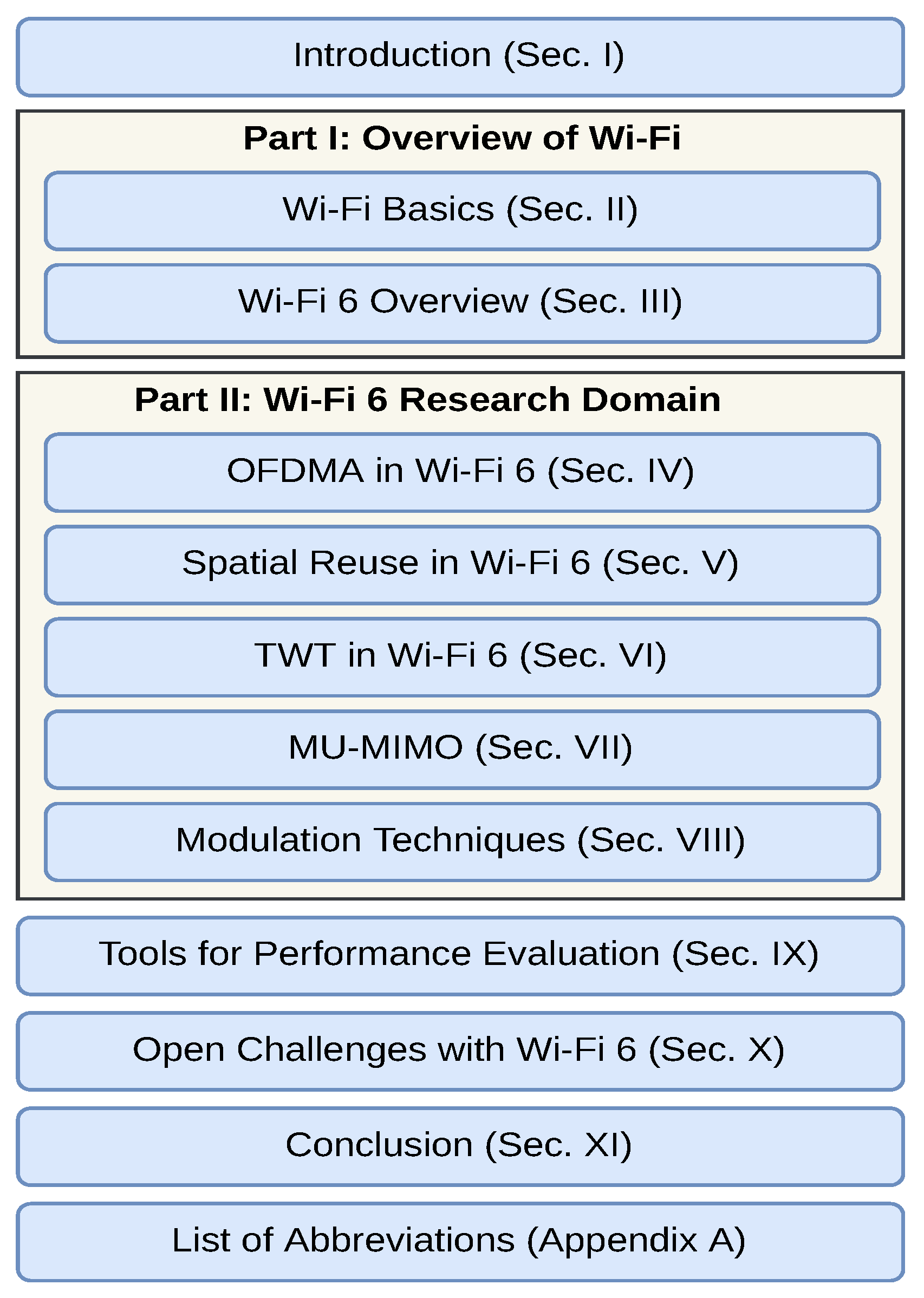
1.2. Paper Structure

The paper is organized as follows and the structure of the paper is depicted in Figure 2. Section 2 gives a compact introduction to thePHY and MAC layers of Wi-Fi generations 1–5 and reviews the history of the Wi-Fi standard. This section is intended to provide Wi-Fi basics for novice readers, whereas expert readers may skip it. Section 3 overviews the novel features of Wi-Fi 6, introduces its novel frequency band, and discusses targeted use cases. Section 4, Section 5, Section 6, Section 7 and Section 8 provide a brief and concise background of OFDMA, SR, TWT, MIMO, and advanced modulation in Wi-Fi 6. They also provide an overview of the deficiencies in previous standards and give a tutorial introduction to the technology, followed by the corresponding related works. The performance evaluation tools utilized for the Wi-Fi 6 studies are discussed in Section 9. Section 10 investigates the open issues in 802.11ax and provides a perspective on future Wi-Fi standards. Finally, Section 11 concludes the paper. A list of acronyms is provided in Abbreviations to facilitate reading.

2. Wi-Fi Basics

This section provides a brief introduction to Wi-Fi and can be skipped by expert readers. We provide an overview of thePHY and MAC layers in Wi-Fi up to Wi-Fi 5. It is the baseline for the improvements to Wi-Fi 6 that are explained in the subsequent sections.

2.1. PHY in Wi-Fi

Recent Wi-Fi standards utilize OFDM modulation, MIMO technology, and modulation techniques for increasing data rates. We introduce these techniques in the following subsections.

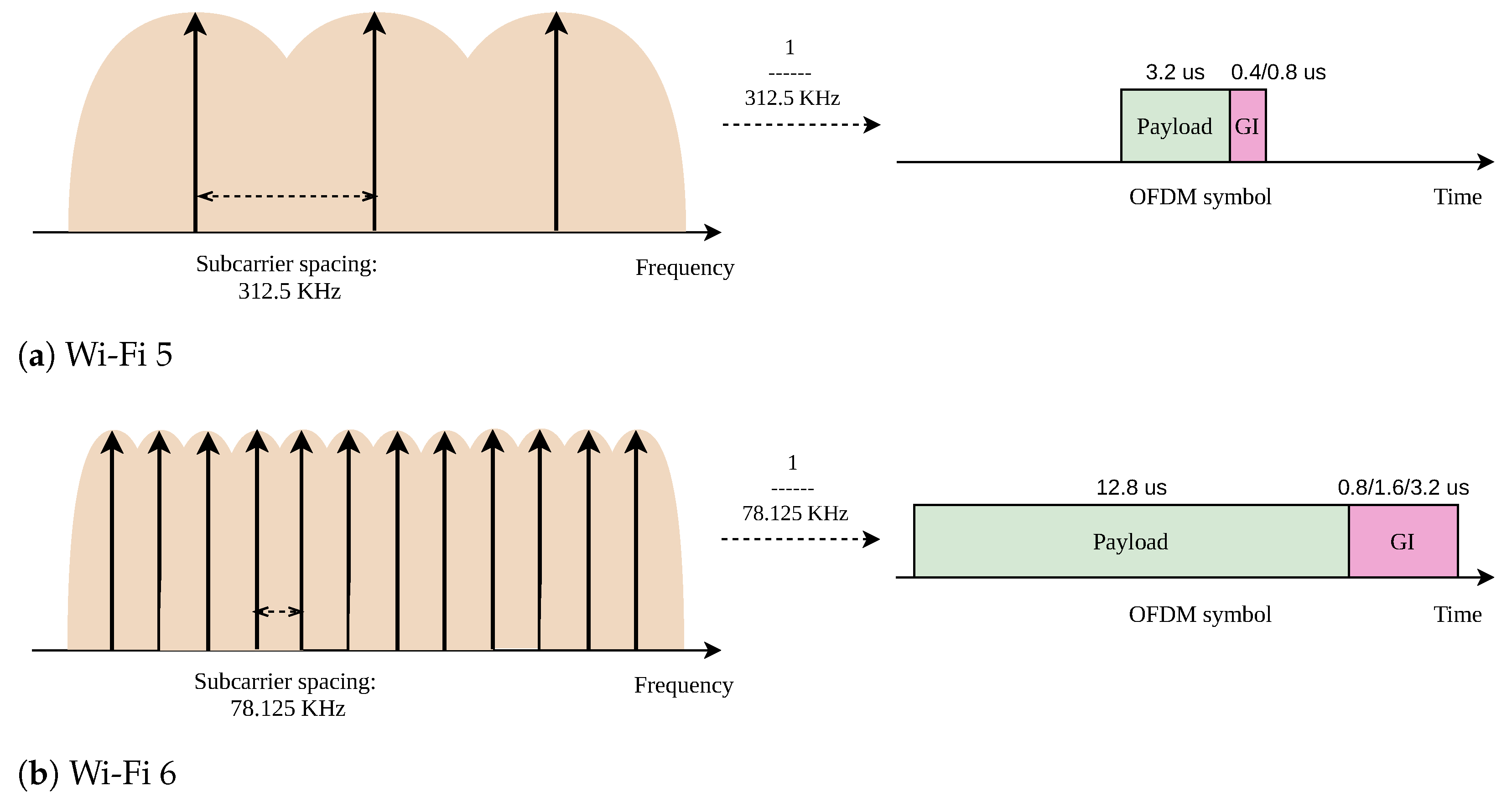
2.1.1. Orthogonal Frequency Division Multiplexing (OFDM)

OFDM is a multicarrier modulation scheme for data transmission in a channel. This means that the channel is subdivided into multiple subcarriers or tones, and data are transmitted in parallel over the subcarriers. The distance between the subcarrier frequencies may be low, e.g., 312.5 kHz in Wi-Fi 5. To minimize interference among the subcarriers, the frequencies must be chosen carefully to be orthogonal to each other. Then, each subcarrier is modulated independently.
OFDM typically spreads the information of a high-bitrate stream over 2 n subcarriers. To that end, m-bit groups are assigned to each subcarrier and converted to a constellation point using QAM. The entirety of all constellation points forms an OFDM symbol. Conversion to electromagnetic waves turns this OFDM symbol into an OFDM signal. An OFDM signal transmits one or multiple concatenated OFDM symbols.
To avoid interference in time, a Guard Interval (GI) is added after every symbol. It is a short time interval between two consecutive symbols that protects against imperfect synchronization as successive transmissions must never overlap, particularly in the case of clock drifts or multipath delay spread. Symbol duration and GI are visualized in Figure 3a. In Wi-Fi 5, the symbol duration is 3.2 μ s long and the GI takes 0.4 μ s or 0.8 μ s .
OFDM in Wi-Fi 2–5 is used for data transmission. A high-bitrate data stream is divided into multiple lower-bitrate data streams. Thus, each subcarrier has a 1 N data rate of the total data rate. As data is transmitted in parallel at a 1 N data rate, the symbol time increases by N compared to the single-tone transmission. Therefore, the OFDM symbol duration has a reverse relationship with the subcarrier spacing. Figure 3 illustrates the relationship between subcarrier spacing and symbol duration in OFDM: smaller subcarrier spacing requires a longer symbol duration.

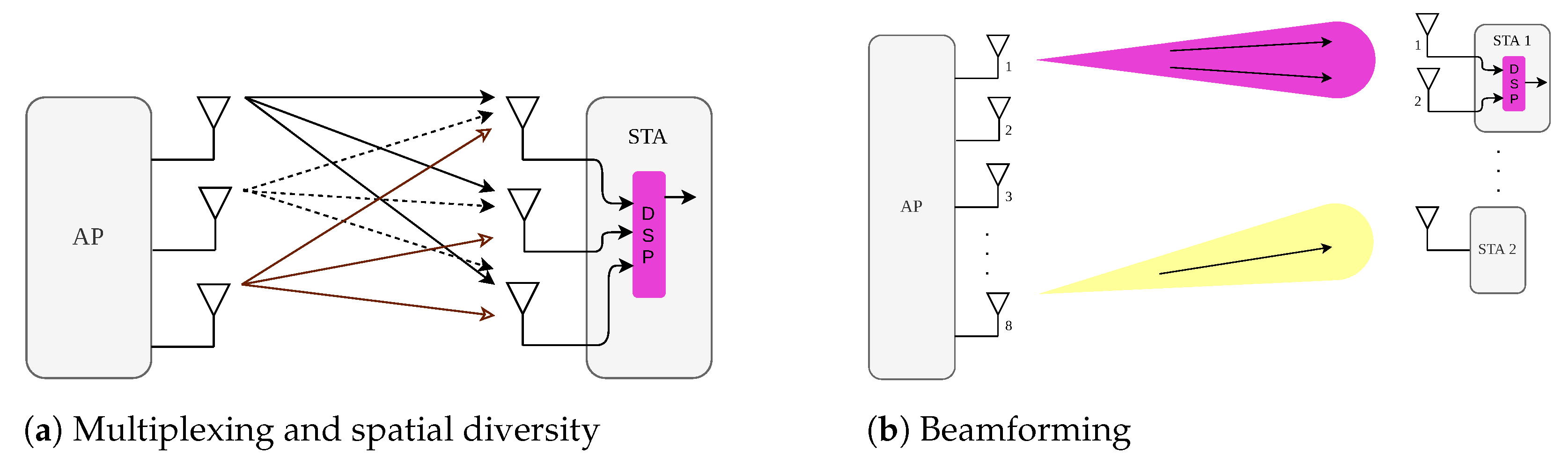
2.1.2. Multiple-Input Multiple-Output (MIMO) systems

MIMO was introduced in 802.11n to overcome the multipath effects that arose with the standards 802.11a/b/g in complex radio environments (because of, e.g., corridors, walls). With MIMO, the signal is transmitted and received simultaneously through multiple antennas, increasing the number of data streams that can be transmitted in parallel.
MIMO offers three different methods for data transmission within a channel:
  • Spatial Multiplexing: Each antenna can transmit independent data signals to the receiver. These data signals are called spatial streams [16]. MIMO increases the throughput linearly with the number of antennas. Figure 4a shows this transmission method.
  • Spatial Diversity: This method turns the multipath effect into an advantage by transmitting the same data over multiple antennas. Since every antenna on the receiver side might receive data copies from other streams too, it provides redundancy. A Digital Signal Processing (DSP) module recombines the received spatial streams to recover the whole data chunk (see Figure 4a).
  • Beamforming: This technique modifies dynamically the radiation pattern of the group of antennas. It is similar to directing the signal in a specific direction to strengthen the signal rather than spreading the energy in all directions. Narrower beams bring stronger signals and reduced interference (see Figure 4b).
In 802.11n, an access point with multiple antennas communicates with only a single station at a time. It may transmit multiple data streams in parallel to the same station but multiple stations must be served sequentially. This feature is also called Single-User Multiple-Input Multiple-Output (SU MIMO).
IEEE 802.11ac (Wi-Fi 5) introduces downlink MU MIMO to serve multiple stations in parallel. Wi-Fi 5 devices support up to eight spatial streams in parallel for downlink transmission. That is, the access point can transmit data to up to four different stations (with two spatial streams per station). MU MIMO leverages a transmit beamforming (TxBF) technique to concentrate the signal in four different directions, i.e., one direction per station.

2.1.3. Modulation

Modulation techniques maximize the number of bits transmitted per subcarrier. Wi-Fi 5 supports up to 256 QAM that modulates 8 bits of information per subcarrier. QAM modulates data in each subcarrier. More bits per OFDM symbol lead to a larger throughput under the condition that the Signal-to-Noise Ratio (SNR) is sufficient. Higher-order modulations are expected to be efficient only under favorable conditions, namely clear environments and short distances.
The coding rate identifies the portion of bits that is used for the transmission of data and Forward Error Correction (FEC). The supported coding rates are 1 / 2 , 2 / 3 , 3 / 4 , and 5 / 6 . A coding rate of 5 / 6 means that 83.3 % (i.e., 5/6) of the data stream is used to carry data and 16.7 % is used to carry FEC.
The combination of modulations namely, Binary Phase Shift Keying (BPSK), Quadrature Phase Shift Keying (QPSK), 16-QAM, 64-QAM, and 256-QAM with coding rates, allow the standard to choose the data rate dynamically according to the radio environment [5]. The Modulation and Coding Scheme (MCS) [17] index comprises a given set of parameters to provide a wide variety of data rates for wireless connections. It is part of the rate adaptation feature in wireless technology and includes the guard interval, coding rate, modulation, channel width, and the number of spatial streams. A discrete list of MCS means that some combinations are impossible (cf. Table 4). For instance, BPSK with a coding rate of 3/4 is not possible.

2.2. MAC in Wi-Fi

We detail here the basic MAC layer features of Wi-Fi.

2.2.1. Distributed Coordination Function (DCF)

Wi-Fi nodes utilize Carrier Sense Multiple Access with Collision Avoidance (CSMA/CA) to share the wireless medium. Before any transmission, a node has to verify that the medium is free for the duration of a DIFS. Then, it engages a backoff phase: the transmitter picks a random value that represents the number of slots that a transmitter has to wait for before transmitting its packet. After each idle slot, the backoff is decremented. Conversely, Wi-Fi implements a residual backoff: the backoff is paused if the medium is busy to maximize short-term fairness. The transmitter has to wait until the medium is free for the period of a DIFS before resuming the countdown. The transmission starts when the backoff is null.
The receiver may acknowledge the correct reception of a unicast packet. More precisely, the ACK is transmitted after waiting for a Short InterFrame Space (SIFS) duration after the reception of the data frame. The transmitter considers a transmission failure if an ACK is not received. It retransmits the frame with the exponential backoff algorithm to progressively reduce the collision probability. This means that a random backoff time is chosen from within an initial contention window, doubling after every unsuccessful transmission attempt.
In Wi-Fi, the hidden node problem may occur, which may severely impact network performance [18]. Consider the topology illustrated in Figure 5. Nodes A and B are within each other’s transmission and interference range; the same holds for nodes B and C but nodes A and C cannot hear each other. As a result, node C may start a transmission, although transmission from nodes A to B is ongoing so B’s reception is impaired.
The Request-To-Send (RTS)/Clear-To-Send (CTS) mechanism has been introduced to cope with the hidden node problem. Before the transmission of a large frame, the sender sends a small RTS packet to the receiver to reserve the medium and the receiver responds with a CTS packet after the duration of a SIFS. The RTS/CTS mechanism ensures that all nodes within the transmission range are informed about an upcoming transmission and defer potential transmission attempts. This prevents C from jamming A’s transmission to B in Figure 5. The duration for RTS/CTS is much shorter than the one for data and ACK together, which drastically reduces the likelihood of collisions.
Each node maintains a Network Allocation Vector (NAV), which represents a record of ongoing transmissions. Since the RTS (resp. CTS) frame contains the duration of the whole frame exchange after the reception of the RTS (resp. CTS), any neighbor of the transmitter and the receiver can update its NAV (Figure 6). In particular, a node cannot transmit any frames if its NAV value is not null. The receiver blocks all its radio neighbors with a CTS until the end of the whole frame exchange.

2.2.2. Enhanced Distributed Channel Access (EDCA)

Enhanced Distributed Channel Access (EDCA) provides QoS for wireless networks by enhancing DCF in legacy Wi-Fi. It introduces prioritized traffic classes, so-called access categories (ACs), and gives prioritized access to higher-priority packets. The nodes label the data packets in the upper layers. EDCA defines four different ACs: video, voice, best effort, and background traffic. AC-specific inter-frame spaces, called Arbitrary InterFrame Space (AIFS), help to handle packets differently. A high-priority station waits for a shorter AIFS time before decrementing its backoff value. Moreover, EDCA enforces AC-specific min/max values for contention windows. EDCA achieves proportional QoS: higher-priority flows obtain more bandwidth than lower-priority flows. Moreover, EDCA assigns larger Transmission Opportunity (TXOP) values for high-priority flows. In this way, the corresponding stations can send several packets back-to-back to increase their throughput compared to the low-priority stations.

2.2.3. Power Management in Legacy Wi-Fi

The use of wireless devices in smart homes, industry, healthcare, etc., has considerably increased in recent years and many wireless devices use a battery as a power supply [1]. Therefore, power efficiency is a critical issue in Wi-Fi. To save energy, legacy Wi-Fi introduced the Power-Saving Mode (PSM) [17]. PSM-enabled stations alternate between active and doze modes. Stations in active mode are ready for transmission or reception. Stations in doze mode save energy by turning off their radio chipsets and are thus unable to transmit or receive packets.
PSM-enabled stations inform the access point that they have started power-saving mode. The access point then starts buffering the packets destined for this sleeping station. The access point piggybacks the list of pending destinations (Traffic Indication Map (TIM)) in its beacons. Thus, stations wake up regularly to receive beacons to check whether the access point has buffered packets for them. Since the beacon interval is indicated in the beacons, a station knows when the next beacons will be transmitted and wakes up slightly before their transmission to cope with clock drifts. More precisely, a station must wake up to receive at least one beacon at every Delivery Traffic Indication Map (DTIM) interval.
When a station decodes the beacon, the station knows if some packets are pending. In the absence of pending packets, the station may switch immediately to doze mode again. Otherwise, it stays active and notifies the access point that it is ready to receive packets. If the station has packets to send, it stays active and uses DCF for transmission.

3. Wi-Fi 6 Overview

The Wi-Fi 6 standard [5] proposes modifications to IEEE 802.11. Its prime goals are improving throughput by at least four times per station compared to IEEE 802.11ac while improving power efficiency and supporting dense networks. Wi-Fi 6 adds new features to thePHY and MAC layers. It also includes some modifications for backward compatibility with legacy devices operating based on IEEE 802.11n in the 2.4 GHz band and IEEE 802.11n/ac in the 5 GHz band [19].
In this section, we elaborate on the latest standard by outlining each feature individually. Next, we introduce Wi-Fi 6E in detail in Section 3.2. Finally, we explain some use cases for Wi-Fi 6.

3.1. Novel Features

Here, we provide an overview of the main novelties introduced by Wi-Fi 6. The improvements they have achieved are listed in Table 5.
Access Points (APs) and Stations (STAs) operating based on the IEEE 802.11ax standard have ““High Efficiency (HE)” as a prefix. To avoid repetition and for simplicity, we use the station and access point as substitutes for the HE station and HE access point. Moreover, we use Wi-Fi 6 as the representative of HE IEEE 802.11ax in the remainder of this paper, and legacy Wi-Fi is considered IEEE 802.11ac.

3.1.1. Orthogonal Frequency Division Multiple Access (OFDMA)

With OFDM, transmissions are spread over several subcarriers, thus requiring the entire spectrum. In dense networks, many stations compete for medium access and increase the collision probability, which reduces the throughput. To overcome this issue, Wi-Fi 6 utilizes OFDMA. With OFDMA, a transmission requires only parts of the spectrum so multiple transmissions can happen in parallel. This considerably reduces contention and overheads on the MAC layer. Thereby, it reduces latency and improves throughput in dense networks.
Although OFDMA has already been used by Long Term Evolution (LTE) networks for downlink multi-user transmission, Wi-Fi 6 supports uplink and downlink transmissions in multi-user mode. However, Wi-Fi 6 hardware also supports OFDM to maintain backward compatibility with the 802.11a/g/n/ac standards. Details of OFDMA in Wi-Fi 6 are explained in Section 4.

3.1.2. Spatial Reuse (SR)

Wi-Fi technology has only a few different frequency channels that may be utilized by neighboring Basic Service Sets (BSSs). When multiple access points are close to each other, the BSSs are overlapping. As a consequence, a transmitting node blocks other transmissions in its BSS and in other BSSs with the same channel, which makes frequency reuse difficult [20].
Wi-Fi 6 utilizes the concept of BSS coloring from IEEE 802.11ah to indicate the BSS in the packet header. A node takes advantage of this information to overhear transmissions of packets from other BSSs. As a result, a node may start a transmission if it estimates that it will not create a collision with ongoing transmissions that are part of another BSS. This improves SR in Wi-Fi 6 [21]. Section 5 explains the details of this feature.

3.1.3. TWT

To maximize the battery lifespan of Wi-Fi stations, the IEEE 802.11 standard defines a PSM [17] (Section 2.2.3). However, stations with traffic to send/receive will compete just after the reception of a beacon, resulting in traffic peaks and collisions. In addition, a station stays awake until all its packets are received and/or transmitted, causing relatively long active times for PSM devices even if they have only a little data to send or receive [22].
To mitigate these problems, Wi-Fi 6 leverages and extends TWT, which was introduced originally in IEEE 802.11ah [23]. The wake times of stations under TWT control are scheduled in advance without overlap. As a result, the standard maximizes the sleep times of the stations and reduces their power consumption noticeably. We discuss TWT in detail in Section 6.

3.1.4. MU MIMO

Wi-Fi 6 proposes both downlink and uplink MU MIMO. Moreover, eight parallel streams are supported. In contrast to Wi-Fi 5, MU MIMO can be applied to only parts of the spectrum in Wi-Fi 6 so that it can be combined with OFDMA. The details are discussed in Section 7.

3.1.5. Modulation Techniques

Wi-Fi 6 defines the 1024-QAM modulation that supports the transmission of ten bits at a time, increasing the data rate by 25% compared to Wi-Fi 5. This modulation scheme is more sensitive to noise so it can be applied only if the channel quality is sufficiently good. Combinations of Modulation and Coding Schemes (MCSs) are defined by an index. Due to the novel modulation in Wi-Fi 6, two novel MCS indices are defined.
Furthermore, Wi-Fi 6 benefits from an optional modulation named Dual Carrier Modulation (DCM) to combat interference for long-distance transmission [5,24]. The modulation improvements are explained in Section 8.

3.2. Additional Frequency Band (Wi-Fi  6E)

The Wi-Fi 6 standard utilizes the 6 GHz frequency band in the range of 5.925–7.125 GHz for unlicensed use with seven 160 MHz channels. They are suitable for video streaming and virtual/augmented reality [25,26]. This new capability is referred to as Wi-Fi 6E (Expanded). It brings wider channels and thereby lower latency and higher throughput than Wi-Fi 6 in other bands. As this band is less occupied by other standards, there is mostly less noise than in other bands, which leads to better performance. There are no backward compatibility issues of Wi-Fi 6E with previous Wi-Fi standards as they do not use this frequency band.

3.3. Targeted Use Cases

The objective of Wi-Fi 6 is to satisfy the requirements of mobile users especially in dense environments, for IoT networks, and for high-bitrate, low-latency multimedia applications. This section describes these use cases and how Wi-Fi 6 resolves challenges.

3.3.1. Dense Environments

In dense environments, multiple access points with overlapping BSSs cohabit within a small area. Wi-Fi 6 supports dense indoor or outdoor environments that require massive access, e.g., apartments, stadiums, university campuses, airports, industrial plants, etc.
Such settings profit from SR as this improves parallel transmissions in neighboring BSSs on the same channel. OFDMA reduces collisions that occur due to a large number of users. Finally, MU MIMO increases the overall capacity needed for massive access.

3.3.2. Internet of Things (IoT)

The world’s Internet traffic is estimated to have manifold growth in the next few years, mainly resulting from Machine-Type Communications (MTC). Each user is expected to have on average 3.6 devices connected to the Internet [1]. IoT devices are widely applied to home automation, industrial automation, autonomous vehicles, healthcare, etc. They are battery-driven and need power-saving features, which are well supported by TWT. Moreover, OFDMA helps to optimize medium access for a massive number of small packets.

3.3.3. Multimedia

In the last decade, multimedia applications with high-throughput and low-latency requirements have become common in mobile devices. Examples are 4K/8K video and audio streaming, online gaming, virtual reality, augmented reality, etc. This traffic surge goes beyond the capacity of legacy Wi-Fi access points [27]. Wi-Fi 6 increases the capacity of access points by higher-order modulation, OFDMA, and MU MIMO, which leads to a better user experience [28].

4. OFDMA in Wi-Fi 6

In this section, we present the advances of Wi-Fi 6 concerning OFDMA and its implications for the MAC layer. Finally, we discuss the research works in this field.

4.1. Advances on the PHY Layer

We first explain how Resource Units (RUs) are used in Wi-Fi 6 to make spectrum usage more flexible, and how a longer symbol duration in Wi-Fi 6 improves efficiency. Finally, we discuss the new frame format.

4.1.1. Flexible Spectrum Usage

A major drawback of OFDM in Wi-Fi is the fact that only a single user can leverage a channel. For every transmission in OFDM, there is a channel access contention overhead, which is significant for small packets.
To overcome this limitation, Wi-Fi 6 introduces Resource Units (RUs). Essentially, the bandwidth of a channel is partitioned in frequency and time, yielding time-frequency blocks. The access points assign these blocks to users for their uplink transmissions. The spectrum of such a time-frequency block is an RU and its duration is called a TXOP. A TXOP is big enough to send one or multiple packets and to receive their acknowledgement. To avoid interference, RUs used by different transmitters must not overlap (i.e., they must use disjoint resources).
The assignment of RUs and TXOPs leads to a time-frequency matrix that enables transmissions between multiple stations and their access point. RUs and TXOPs make bandwidth usage more flexible: a station may use wider (resp. narrower) RUs and shorter (resp. longer) TXOPs. Moreover, multiple parallel transmissions within a single channel are possible.

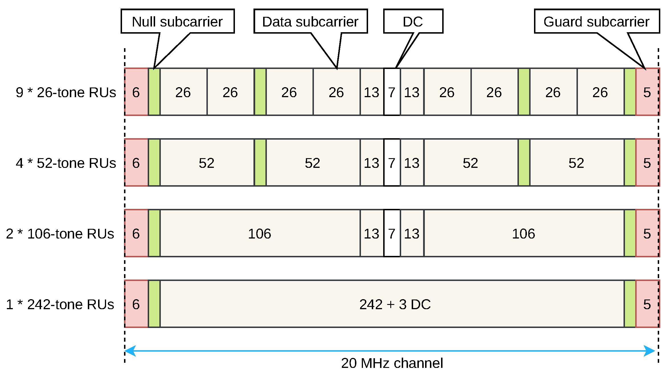
4.1.2. RUs in Wi-Fi 6

To support fine-bandwidth granularities, Wi-Fi 6 uses a subcarrier spacing four times narrower than Wi-Fi 5 (78.125 kHz vs. 312.5 kHz), which is visualized in Figure 3b. Narrower RUs compared with legacy Wi-Fi help to increase the robustness of multipath but they are also more sensitive to noise. The number of available RUs within a channel depends on its bandwidth and the RU. For instance, an 80 MHz channel bandwidth may contain a single 996-tone RU or 16 orthogonal 52-tone RUs. Table 6 lists all possible RU sizes and the maximum number of RUs according to the channel width.
Figure 7 depicts the various RU sizes supported in a 20 MHz channel. We have:
  • data subcarriers: these subcarriers transport data;
  • guard subcarriers: these subcarriers comprise 11 tones in total in a 20 MHz channel and are located at the beginning and end of the channel;
  • null subcarriers: these subcarriers separate different subcarriers; with guard subcarriers, they help to relieve interference from adjacent channels and sub-channels;
  • DC (direct conversion) subcarriers: these subcarriers indicate the center of the channel; their sizes may differ depending on the RU sizes.

4.1.3. Duration of Symbols and Guard Intervals in Wi-Fi 6

Due to shorter subcarrier spacing, the symbol duration in Wi-Fi 6 has been updated with different Guard Intervals (GIs) (Figure 3). A longer GI increases the tolerance to jitter across users and leads to higher efficiency and throughput in the uplink MU OFDMA compared to Wi-Fi 5. Thus, the bandwidth wasted by the GI is reduced. The larger GI values are applied to combat the signal delay spread in outdoor environments [29].

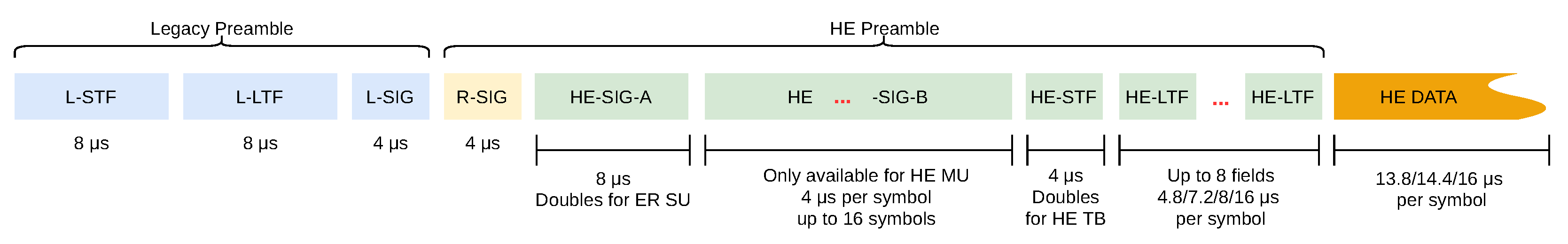
4.1.4. New Frame Format

Four new frame formats and preamble fields are introduced to support the new features and functionalities of Wi-Fi 6. The general structure of the frame remains similar to legacy Wi-Fi for backward compatibility and coexistence. Figure 8 depicts these new frame formats. The preamble of the incoming packet includes specific fields to identify the used sub-channels and the frame format. The new preamble consists of two parts, legacy (non-HE) and HE fields. The legacy fields support IEEE 802.11n/ac and the HE fields are only readable by Wi-Fi 6.
The four different types of HE Physical Layer Protocol Data Units (PPDU) are distinguished by the preamble fields [5]:
  • HE Single-user (SU) PPDU: this frame is used for single-user transmissions.
  • HE ER SU PPDU: this frame is the same as the single-user transmission but designed for outdoor environments with an Extended transmission Range.
  • HE MU PPDU: this frame is considered for one or multiple downlink transmission(s) by adding the HE-SIG-B field to the single-user transmission frame.
  • HE Trigger-Based (TB) PPDU: this frame is used for multi-user uplink transmissions in response to the Trigger Frame (TF) issued by the access point.
The new HE preamble fields that differentiate the frame formats are the following:
  • Repeated Legacy (non-HT) SIGNAL (RL-SIG): This field detects the beginning of the HE frame.
  • HE-SIG-A: This field is a common field in all four Wi-Fi 6 frame formats. It carries all the needed information for the types of transmissions and is two OFDM symbols long. The information in this field differs depending on the frame type and whether the transmission is single-user, multi-user, or TB. It contains information about the packet to determine the link type (uplink or downlink), BSS color, TXOP duration, bandwidth, number of spatial streams, and coding [30]. For an extended-range single-user transmission, this is repeated one more time to improve the robustness against interference and signal fading in outdoor scenarios [31].
  • HE-SIG-B: This field is specific to downlink multi-user transmissions. It is divided into two parts. In the common part, it carries RU allocation information and it is decodable by all the stations in the same sub-channel. The user-specific part has a variable length and contains specific information for each user such as MCS, number of spatial streams, coding, and station ID [32].
  • HE-STF and HE-LTF: The HE short training field (STF) and HE long training field (LTF) are specific to MIMO operations. The former synchronizes a receiver with the incoming frame in time and frequency. The latter is responsible for beamforming and spatial diversity. For a TB frame, the duration of the HE-STF is twice as long.

4.2. Advances on the MAC Layer

Wi-Fi 6 introduces OFDMA to synchronously transmit multiple flows over disjoint RUs. MAC mechanisms have to be adapted to support multiple transmissions in parallel. Wi-Fi 6 extends the MAC layer so that legacy devices are still supported. In the following, we first introduce the extensions of the RTS/CTS mechanism, detail downlink and uplink transmissions, and then elaborate on the integration of the new mechanisms with EDCA.

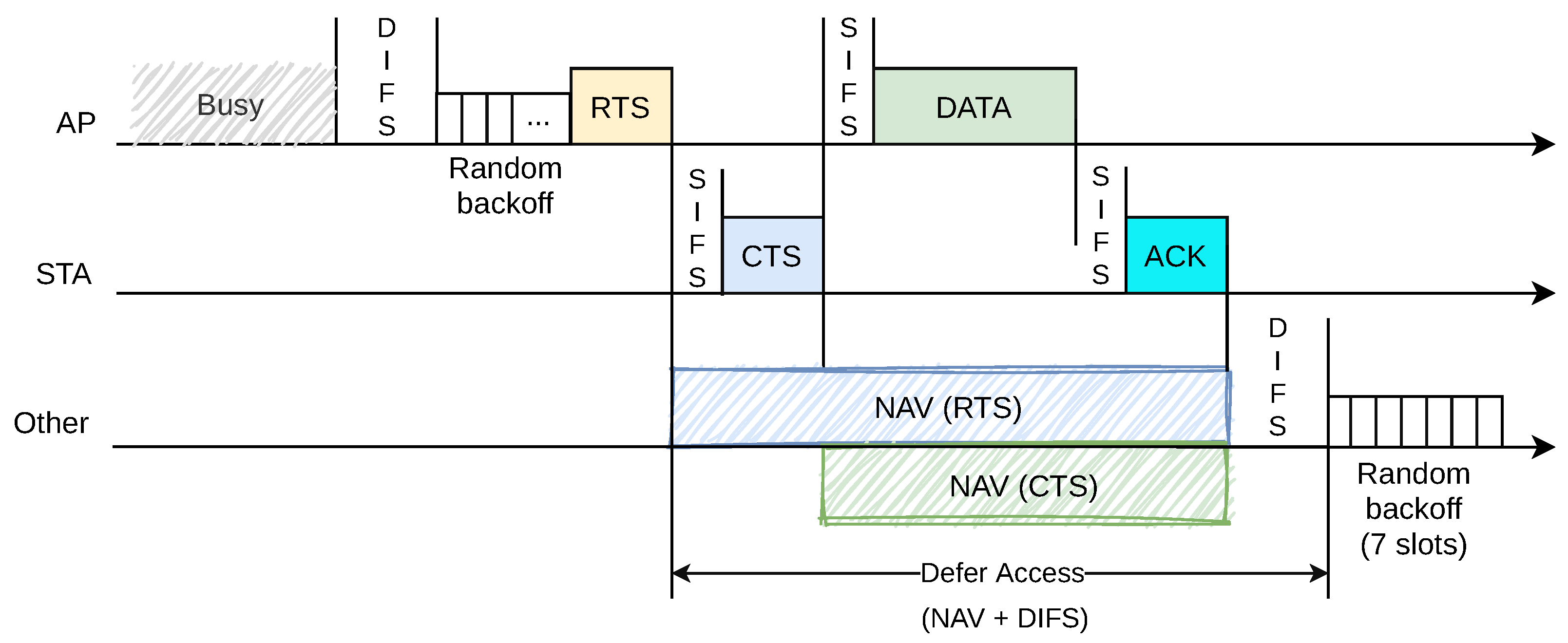
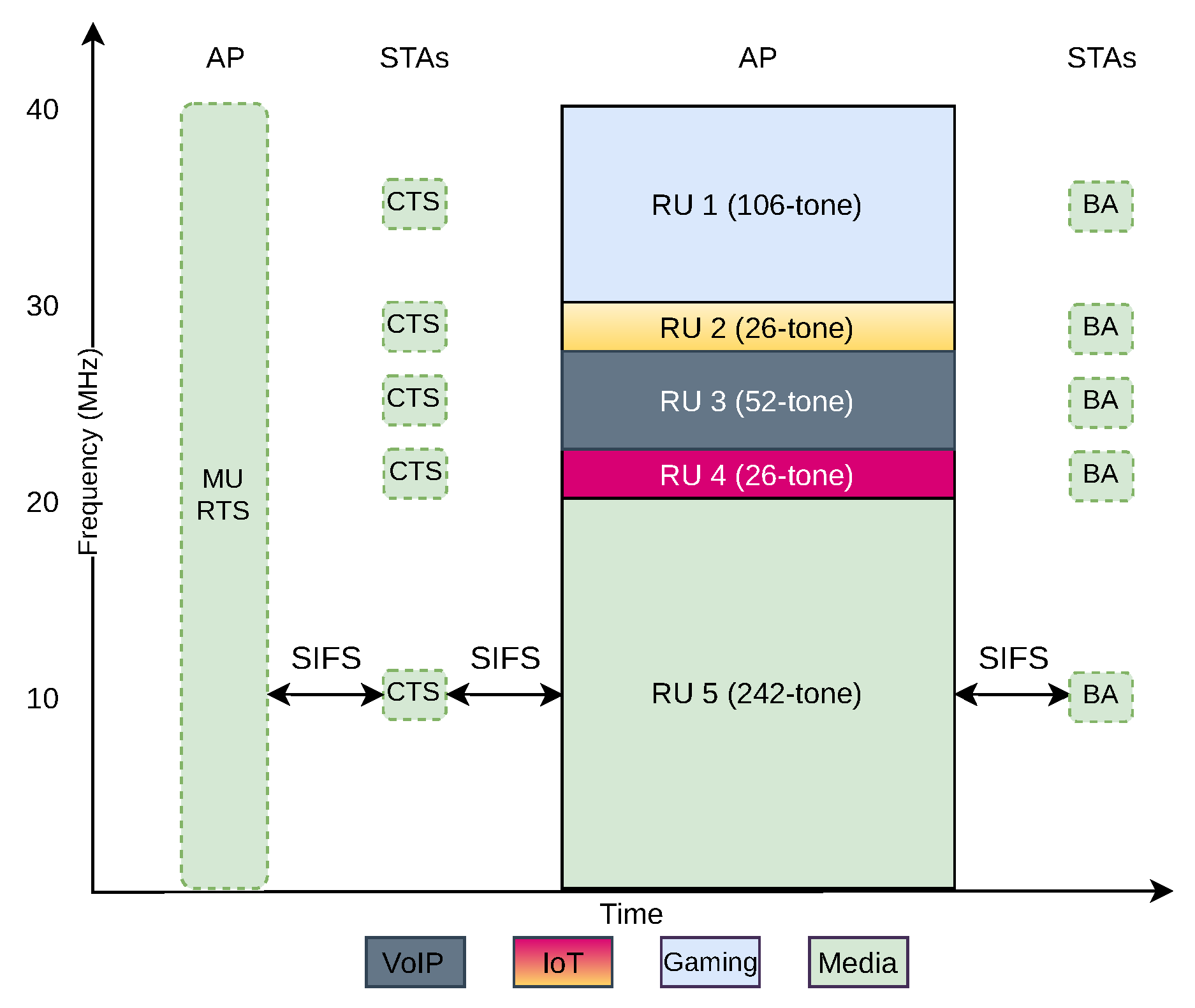
4.2.1. Multi-User RTS/CTS Handshake

Wi-Fi 6 extends the legacy RTS/CTS handshake to a multi-user one. Indeed, OFDMA implies that several transmitters/receivers may be active simultaneously using different RUs. Thus, the RTS/CTS has to inform all the neighbors about the RUs and TXOP selected for the next ongoing transmissions [33]. The mechanism also has to accommodate multiple receivers and transmitters. For both RTS and CTS, the lowest modulation is used so that all stations can decode them.
To accommodate multi-rate environments, Wi-Fi 6 uses a duration-based threshold to trigger the RTS/CTS handshake. Indeed, transmission time is a better resource measure than packet size.The access point tunes the RTS/CTS threshold effectively to avoid interference and maximize efficiency [5,11]. The access point is always awake to have a complete view of medium activity, whereas some power-saving stations may provisionally turn off their radio chipsets.

4.2.2. Downlink Transmission

The entire procedure for downlink transmission is depicted in Figure 9. The access point knows the data to be sent toward all stations and can schedule the RUs to the receiving stations for the next TXOP. Then, it transmits a multi-user RTS frame and the stations respond with a CTS to the access point through their scheduled RUs. Afterward, the access point simultaneously transmits the entire data on the scheduled RUs to the receiving stations. The transmission possibly covers multiple packets. When the transmission is over, the stations acknowledge the correct reception of the data with a single Block Acknowledgment (BA).

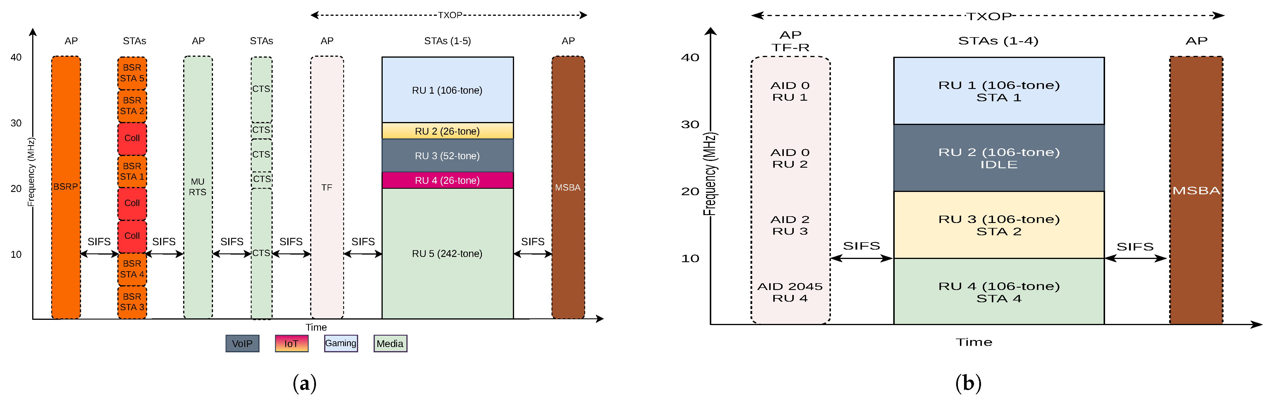
4.2.3. Uplink Transmission

Uplink transmission is more complex than downlink transmission because the access point must learn about the stations’ demands and inform the stations about the transmission parameters. For this purpose, there are two approaches that we present below: uplink OFDMA scheduled access and UORA.

Scheduled Access

With scheduled access, the access point schedules all the RUs for the next TXOP to the stations, which prevents contention among the stations. The access point learns about the stations’ demands either from Buffer Status Reports (BSRs) that piggybacked on earlier data transmissions or explicitly asking the stations with a Buffer Status Report Poll (BSRP).
Figure 10a illustrates scheduled access with polling. The access point sends a BSRP including the list of RUs for BSR transmissions. The stations randomly choose one of these RUs to send their BSR to the access point. Based on this knowledge, the access point schedules disjoint RUs to the stations for the next TXOP and notifies them with a multi-user RTS/CTS handshake. The transmissions are protected from hidden terminals after the reception of all CTSs.
The access point then broadcasts a Trigger Frame (TF) to distribute the parameters for the uplink transmissions. It contains a list of available RUs and AID values, which maps resources to stations, as well as optimized transmission parameters (MCS, target Received Signal Strength Indication (RSSI), FEC coding type, and more).
When the schedule is announced, all other transmissions are interspaced by the SIFS. Thus, no collisions can occur after the reservation is made by the access point. Afterward, the stations start their transmissions on the assigned RUs for the proposed TXOP. At the end of the TXOP, the access point broadcasts a single Multi-Station Block Acknowledgment (MSBA) via OFDM using the entire channel. It is sent with the lowest modulation to be decodable by all stations. The message lists all correctly received frames during the last TXOP.

Random Access

Although scheduled access assigns all RUs to specific stations, random access leaves at least some RUs for the stations to be used in contention mode. Moreover, there is no multi-user RTS/CTS handshake to limit the overhead.
The access point triggers UORA mode. The access point first broadcasts a list of available RUs for random access in a Trigger Frame Random (TF-R) [34]. This is a Trigger Frame (TF) with at least one RU for random access instead of scheduled access. The TF-R sets the Network Allocation Vector (NAV) for legacy stations instead of an RTS/CTS handshake. The TF-R also contains a list of available RUs and AID values. Here, an AID of 0 stands for the associated stations and an AID of 2045 stands for the unassociated stations. Any other AID value corresponds to scheduled access. Thus, an associated (resp. unassociated) station can contend for any RU with an AID equal to 0 (resp. 2045). In particular, a station does not create collisions with scheduled frames when it engages an association.
Upon the reception of the TF-R, all associated/unassociated non-scheduled stations that have data to send try to access one of the available random-access RUs. Each station adapts CSMA/CA by decrementing its backoff counter independently for each of the RUs assigned for the random access in the TF-R [35]. The winning stations transmit their data in the accessed RUs. Finally, the access point acknowledges the received packets by a Multi-Station Block Acknowledgment (MSBA).
Figure 10b illustrates the mechanism with four contending stations. Stations 1–3 are already associated with a member of the BSS, having AIDs 1, 2, and 3, respectively, whereas station 4 is unassociated. As RU 3 is assigned to AID 2 (station 2), there will be no contention for its resources. Conversely, RUs 1 and 2 are for any associated station (AID 0). We assume that the backoff of station 1 is equal to zero and it competes in RU 1 (it would have selected RU 2 if its backoff was equal to 1). Station 3 has either no frame to send or its backoff value is strictly larger than 1 (it will be decremented by two after this UORA phase). Finally, RU 4 is reserved for the unassociated stations (AID 2045). We further assume that the backoff of station 4 is equal to zero so it tries to compete in RU 4.

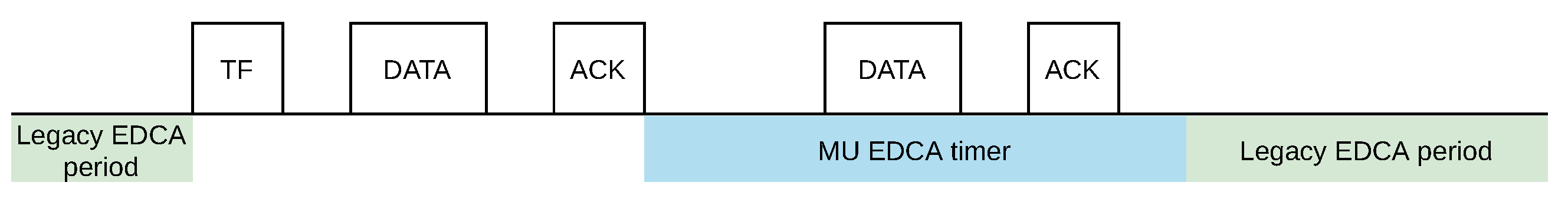
4.2.4. Integration of EDCA

For backward compatibility, a Wi-Fi 6 access point must support both legacy Wi-Fi and Wi-Fi 6 stations. However, legacy Wi-Fi stations support only OFDM access, whereas Wi-Fi 6 transmissions may be multiplexed with OFDMA. Thus, the access point will switch between two modes: (i) transmissions in OFDMA with only Wi-Fi 6 stations and (ii) transmissions in OFDMA with legacy Wi-Fi stations. In particular, the access point must exclude legacy Wi-Fi stations when an OFDMA phase engages. To exclude these stations, the access point can tune the EDCA parameters. Examples are the AIFS Number defining the inter-frame space and the minimum and maximum contention windows.
Wi-Fi 6 defines two sets of EDCA parameters:
1.
Legacy EDCA parameters are applied for non-Wi-Fi 6 stations and Wi-Fi 6 stations in single-user mode;
2.
Specific multi-user EDCA parameters are used when several transmissions are multiplexed over multiple RUs. Stations use these parameters after an uplink multi-user transmission from the access point [11,36]. Conversely, they re-apply the legacy parameters when the multi-user transmissions are terminated.
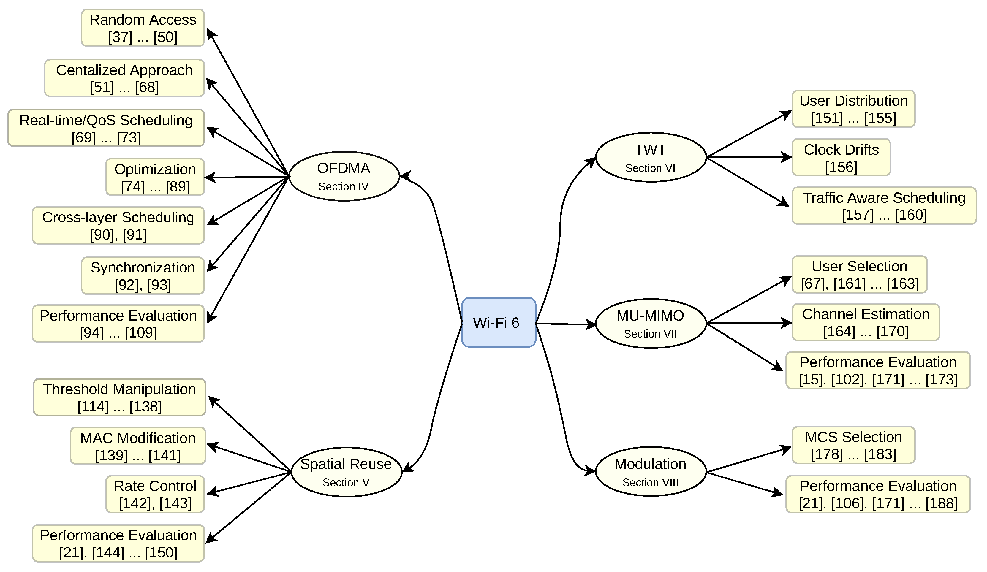
Figure 11 depicts the MU EDCA procedure. When the station receives the TF, it applies the multi-user EDCA parameters for channel access, starts transmission, and sets the timer to listen for upcoming TFs to update the timer. If it does not receive a new TF and the timer expires, it falls back to legacy EDCA mode.

4.3. Related Work

Wi-Fi 6 provides a framework for scheduling data transmissions but does not propose any specific scheduling algorithms. Therefore, a large number of papers focus on the scheduling process. We review the related works concerning random access, centralized approach, real-time/QoS scheduling, optimization, cross-layer scheduling, synchronization, and performance evaluation.

4.3.1. Random Access

CSMA/CA means that collisions may arise that negatively impact the throughput and the energy efficiency. Thus, many propositions adapt random access to reduce the number of collisions.
Some approaches added an additional exponential backoff procedure. For instance, hybrid UORA [37] used a multi-carrier CSMA analytical model based on Markov chains. A station first uses a primary backoff as usual to grant a TXOP for its data transmission. However, instead of transmitting its frame immediately, the station may engage a secondary backoff procedure according to a given probability depending on the Markov model. The secondary backoff counter reduces the number of collisions among the selected stations for the transmission. The entire procedure takes place within a TXOP. CRUI [38] also relied on an extra backoff stage during which each station sends a busy signal at a given offset depending on its priority. Only the station with the largest priority, i.e., with the earliest busy signal, wins the contention and is allowed to transmit for the corresponding TXOP. A winner can also grant the rest of the TXOP to a secondary station with a lower priority when it has finished transmitting its frames.
Some other approaches tried to find the optimal backoff selection parameters or applied the backoff differently. Kim et al. [39] concluded that the number of stations does not increase the contention probability if the OFDMA contention window is tuned optimally. Therefore, they proposed a distributed backoff counter controller. Every station adjusts its backoff counter regarding the earlier transmission’s success or failure. If the earlier transmission is successful, a station will decrease its backoff counter to allow other stations to allocate more RUs and vice versa in case of transmission failure. Wang et al. [40] minimized latency and improved throughput by retransmitting without the backoff procedure. The station had a second transmission opportunity for unsuccessful transmissions with a complementary probability. This method is effective when the number of stations is less than the number of random access RUs.
Xi et al. [41] proposed a multi-dimensional busy-tone approach to solve contention among stations that use the same RU. More precisely, each station selects a random backoff value and sends a signal during the arbitration phase’s sub-slots that corresponds to one in its backoff value. Thus, the station knows that it lost the TXOP if a signal is received during a sub-slot corresponding to a zero in its backoff value. A turnaround time is required during each sub-slot so that a station can switch its radio chipset from transmission to reception. This significantly complicates the implementation and wastes radio bandwidth. In addition, these approaches break the compatibility with other Wi-Fi 6 devices.
Artificial intelligence techniques have also been applied to optimize performance. The deep reinforcement learning technique, more specifically a convolutional neural network, was exploited to propose a distributed RU selection scheme to improve throughput and delay [42]. The scheme operates with CSMA/CA to enable a station to select the right RU considering a fixed number of previous channel allocations. Likewise, ref. [43] applied two other techniques, namely deep Q-network (DQN) and deep deterministic policy gradient (DDPG). The authors who leveraged those methods predicted the optimal contention window size regarding past behaviors to achieve high network throughput.
Islam et al. [44] proposed a hybrid MAC to assign RUs to stations in two steps. Firstly, RUs are fairly distributed among the stations. Then, multiple stations that select the same RU contend to access the RU using the legacy CSMA/CA method. However, such an approach is static and assumes that each station generates the same amount of traffic. In addition, it just reduces the collision probability but may not function efficiently in dense networks. Lee et al. [45] proposed hybrid channel access to alleviate the collisions in dense networks. Firstly, they modeled the upper bound efficiency of random access concerning the number of stations, contention window, and available RUs. Next, they adjusted the OFDMA contention window for uplink OFDMA to its optimal value to produce results similar to the developed model.
Bhattarai et al. [46] proposed to fairly allocate the optimal number of random and scheduled RUs to provide high throughput. The access point assigns scheduled RUs to the stations from which it received a BSR. Then, it leaves the remaining RUs for other stations to contend for the channel access. Efficient Resource Allocation (ERA) [47] classified stations according to their load. Three classes were created with a different RU width to accommodate the different traffic loads. Stations with more traffic to send are assigned to an RU with a larger bandwidth.
Baiocchi et al. [48] adapted Wi-Fi 6 to implement random access in the frequency domain. The stations send tones (i.e., non-modulated signals) to compete for medium access. An ordered list of subcarriers is used to transmit the tones: only the stations that do not detect any tones transmitted through a lower subcarrier win the round. After a few rounds, the collision probability becomes very small.
The authors of [49] offered a better user experience by enabling the access point to assign the stations to multiple groups. Then, it assigns the resources to each of these groups. The authors defined a utility function based on the user data rate and minimum bandwidth requirement. The access point applies K-mean clustering based on the closeness of the stations’ utility functions to group the stations. Finally, it assigns RUs to these groups to have a maximum utility value per group.
Conversely, we can adopt a user-centric (selfish) approach: each user can independently select its access point while trying to globally balance the load [50]. A station considers the signal strength of the neighboring access points as well as its relative capacity, achievable data rate, and the location of other stations. Since this method is user-centric, it greatly reduces the overhead, but the system may fall in a local optimum, or even worse may result in oscillations.

4.3.2. Centralized Approaches

Access points may execute a centralized scheduling scheme to assign RUs to different users. Some works aimed to maximize efficiency. Karaca et al. [51] investigated the impact of the PPDU duration. Indeed, a fixed PPDU means less flexibility. If different stations do not have the same amount of traffic to forward, padding is required. They determine the scheduling duration according to the padding overhead, the airtime fairness, and the energy consumption. The authors demonstrated that their algorithm is close to the optimal strategy through a Lyapunov optimization.
The authors of [52] applied a deep reinforcement learning technique to optimize the MAC layer resource allocation. The contending station measures the channel collision probability considering all the observed timeslots between two consecutive backoff stages. Using this probability, it calculates the optimal contention window size. Then, they applied a Q-learning technique to optimize the performance of the mechanism.
Bankov et al. [53] considered the RU allocation as an optimization problem. The target was to find the best pair of RUs and MCSs for each station. However, Wi-Fi 6 presents specific properties that must be considered during the scheduling process. In particular, Wi-Fi 6 restricts the usage of RUs. For instance, a 106-tone RU cannot be randomly located in a 40 MHz channel. They applied the Hungarian algorithm [54] to compute the most efficient scheduling matrix. Considering this optimization task, they also adapted three LTE schedulers to the Wi-Fi 6 constraints. Tutelian et al. [55] introduced a utility function for the quality of the RUs considering the number of stations, available RUs, and MCSs. The utility function value is the transmission rate that depends on the RU and the MCS. They used a greedy heuristic to solve the optimization problem. The stations are sorted in descending order according to the utility function. The widest RU is assigned to the first station in the list and this assignment continues until all stations are scheduled. The same round is repeated for the MCS assignment.
The following articles focused on maximizing the sum of the rates achieved individually by each of the emitters in the network. The authors of [56] aimed to maximize the utility of the long-term average rates of stations. To do this, they solved the optimal uplink resource allocation problem by employing Lyapunov optimization, respecting the average rate and power constraints. Wang et al. [57] solved a relaxed resource allocation problem via a divide-and-conquer algorithm where a user can be assigned to multiple RUs. However, a station should receive at most one RU for its transmissions, increasing the complexity as the optimal assignment requires an exhaustive search. Thus, two heuristics, greedy or recursive, can help to solve the original assignment problem, allocating one RU per station. An extended version [58] also considered fairness among users.
Some papers utilized scheduled and random accesses together. The authors of [59] proposed a hybrid mechanism for channel utilization. They introduced three control packets to collect and send information with limited flexibility in network size. This mechanism was an alternative for TF-R and is now deprecated. In the beginning, the access point acquires the demands and assigns the RUs to the requesting stations. Stations that did not ask for a dedicated resource and have data to send can contend to access the remaining non-allocated RUs. Yang et al. [60,61] also leveraged a utility metric to maximize utility and user satisfaction. They managed the RU transfer between scheduled and random access users. Moreover, they suggested a scheduling scheme to distribute the RUs by accounting for the probability distribution of multi-cell interference. The authors of [62] proposed hybrid channel access in the channel contention phase to assign the RUs efficiently. In the contention phase, the stations with expired backoff randomly select RUs to send the BSR. Then, other stations sense the channel to find free RUs. They resume the backoff counter and try to select one of these resources. The procedure continues until all the stations successfully allocate resources or there are no more RUs.
The authors of [63] grouped the stations in a BSS to reduce collision and interference. They clustered the geographically close stations. Each cluster has a leader station that contends to access the channel for the whole cluster. The access point schedules these leaders and subsequently, leaders schedule their member stations based on their available resources. However, it needs to modify the Wi-Fi 6 standard.
Joo et al. [64] improved the throughput by making the network capable of sharing a single RU among multiple stations. Virtual timeslots within an RU distinguish the timing for each station’s access to the medium.
The authors of [65] leveraged OFDMA to enable unidirectional full-duplex transmissions. The access point has self-interference cancellation antennas so that it can both transmit and receive different signals. However, the stations do not have this kind of complex hardware and they are not full duplex. Thus, the access point must identify the hidden terminals. They use two OFDM symbol times for signaling. In the first OFDM symbol time, the access point gathers the uplink transmission demands of the stations. In the second OFDM symbol time, it compares these demands with its downlink traffic and finds the hidden stations accordingly. Then, transmissions can take place, full-duplex for the access point and half-duplex for the receiving stations.
Karthik et al. [66] adapted EDCA to OFDMA to enable priority access. The access point executes a scheduler that assigns different contention window sizes to each station. More precisely, the EDCA algorithm is executed virtually by the access point to decide the station that will use each RU within a PPDU. Because of the virtual execution, no collisions are actually created; the access point selects a single winner. The station receives an RU if its backoff value is smaller than the available RUs. The RU size that the station allocates is a factor of 26-tone RU. It defines a limit for the number of 26-tone RUs participating in a single transmission using the Min–Max and Z-score normalization functions.
Kim et al. [67] proposed a new multi-user OFDMA frame format to maximize transmission efficiency. They proposed to find the optimal length of the multi-user frame, considering the status of the buffer and the bitrate of the stations. They proved that the problem is NP-complete, and decomposed it into subproblems that they solved sequentially.
CC-MAC [68] is a centralized contention-based MAC that exploits uplink OFDMA random access. Firstly, the access point sends a Contention Period Announcement (CPA) frame. Then, each active station selects a random slot after the CPA to send an association ID signal. Thus, the access point knows the list of pending frames and announces the winners in a Contention Resolution (CR) frame. If the number of winners is strictly larger than the number of RUs, the access point must select a subset to announce in its CR frame. Finally, the winning stations can start their transmission synchronously. This mechanism is an alternative to BSR and TF concepts.

4.3.3. Real-time/QoS Scheduling

The support of real-time flows is becoming dominant for novel Wi-Fi usage such as industrial applications (see Section 3.3). In particular, the MAC layer must be able to guarantee a bounded latency for high-priority flows and provide QoS to assign a larger bandwidth to critical flows. Hopefully, Wi-Fi 6 relies on a schedule of transmissions and may work without collision when the access point knows the requests of each station. Filoso et al. [69] considered latency-bound traffic with strict deadlines. They prioritized emergency messages and enqueued them in an emergency queue. Depending on the number of packets in the emergency queue and the maximum number of devices to transmit simultaneously, flows are scheduled in parallel and assigned to RUs to meet the waiting deadlines.
Traffic asymmetry has already been identified as a key problem in legacy Wi-Fi [70]. Indeed, the stations and access point have the same priority for medium access, whereas the access point transmits more packets. Khorov et al. [71] corroborated the inefficiency of trigger-based OFDMA while the Wi-Fi 6 access point was competing with legacy stations for channel access. To be able to give more transmission opportunities to the access point, they proposed to use different EDCA parameter sets for the access point and legacy stations.
Reliability and data delivery are also critical for providing QoS. Cyclic Resource Assignment (CRA) [72] targets real-time applications (RTA) to meet the critical latency and reliability constraints. Primarily, it randomly schedules stations and assigns 26-tone RUs to them. Therefore, it can schedule a large number of stations in parallel. In the case of collision, the access point specifies an RU to the stations to transmit without collision. The authors of [73] focused on time-sensitive traffic. To predict data stream deadlines on the access point, the access point regularly retrieves the stations’ queue sizes through BSR. This provides a realistic approximation of the stations’ deadlines and then assigns the RUs to the stations based on the estimated deadlines. Thereby, it minimizes packet loss significantly.

4.3.4. Optimization

Interactive flows are sensitive to latency. Bankov et al. [74] proposed, e.g., to minimize the upload time in uplink OFDMA. They greedily picked different stations according to their remaining upload time and assign them to different RUs. The authors of [75] applied a queue-based drift plus a penalty algorithm [76] to select the transmit power and resource allocation per timeslot to minimize the queue length. It divides the period between two consecutive TFs to multiple timeslots and allocates the RUs per timeslot, i.e., it is large enough for transmission. Zheng et al. [77] doubled the OFDMA contention window in the case of a station’s failure. More precisely, this happens when the number of the unsuccessful transmissions exceeds the retransmission limit or when the number of active stations exceeds the number of available random access RUs Kim et al. [78] clustered stations with similar expected transmission delays to transmit their data simultaneously. This enhanced the uplink channel usage. The transmission scheduling was based on a proportional fair-based approach.
Throughput optimization was the main objective of the following works. The authors in [79] concentrated on optimizing the network’s capacity when mixing scheduled and random access. Primarily, they defined the capacity entropy to measure the capacity of the network. Then, they modeled UORA mode with a Markov chain to derive the access probability and thus the capacity of the random access mode. Finally, they proposed a hybrid mode that relied on a greedy algorithm. The formulation relied on a set of constraints, defining the capacity and the channel quality perceived by each station. Chen et al. [80] determined the contention window size utilizing deep reinforcement learning to optimize the throughput. It monitored the network under different circumstances and set the window size accordingly. A Markov decision process solved the optimization problem by taking into account the current window size, status of the nodes, and network throughput.
The following papers aimed to improve the throughput with a constraint on queue length. A scheduling mechanism for downlink OFDMA with minimum throughput requirements wass introduced in [81]. It was modeled with a Lyapunov optimization, considering a weighted Max–Min fairness. The authors derived a near-optimal scheduling policy to maximize the throughput. The OFDMA scheduler in [82] aimed to maximize the throughput and minimize the end-to-end latency in a multi-user scenario for both downlink and uplink. This optimization problem considered the queue length, MCS, and traffic priority of stations to assign optimal RUs to the clients. Likewise, Filoso et al. [83] considered the priority and fairness jointly while allocating RUs for stations. Queue length and data priorities served as inputs to a closed-loop feedback controller.
Since Wi-Fi 6 exploits the unlicensed band, some approaches tried to maximize the throughput with co-existing networks. The authors of [84] maximized the total network throughput by proposing a probabilistic channel aggregation mechanism and applying a deep reinforcement learning technique to tune the probabilities. The objective was to maximize the sum of the throughput of the Wi-Fi 6 and legacy stations. If an RU is partially utilized, the station should sense it with a higher probability for aggregation. The authors of [85] investigated the coexistence of WLAN and LTE systems. They maximized the network throughput by grouping the nodes in Wi-Fi and LTE networks. They solved an optimization problem using a genetic algorithm to find the optimal grouping with the constraint on packet delay.
The authors of [86] improved the throughput and reduced the delay by determining the contention window to avoid collisions. The mechanism calculated the optimal contention window size according to the number of backoff stages and conditional collision probability. Cheng et al. [87] implemented a traffic load perception mechanism to actively switch between random access and scheduled access. The mechanism switches to scheduled access when the traffic flow crosses the threshold and for the rest of the transmissions, it utilizes random access. The threshold value is computed to minimize the delay and maximize the throughput.
The authors of [88] proposed an aware-backup padding automatic repeat request (ARQ) solution for multi-user transmissions. Instead of padding an A-MPDU frame with dummy bits to align the duration of all the transmissions, the authors introduced backup packets. More precisely, a transmission is lost when an error occurs in both the original and the duplicated subframes. Since Wi-Fi 6 already handles duplicated frames, this scheme is still standard-compliant and may cohabit with legacy Wi-Fi 6 stations. The objective of [89] was to use the minimum number of access points while providing fault tolerance and user satisfaction. An analytical model considering channel assignment and power adjustment was derived in an early step. Then, a heuristic algorithm based on a greedy approach was introduced to solve the NP-hard optimization problem.

4.3.5. Cross-Layer Scheduling

Sharon et al. [90] introduced three scheduling mechanisms for unidirectional TCP downlink transmission. The first solution enables stations to send back TCP acknowledgments within the same TXOP without initiating uplink transmission. By accelerating the TCP feedback, the sender can increase its throughput faster. In the second mechanism, both the access point and the stations contend to access the medium using EDCA. The access point serves the stations in a round-robin order and if a station wins medium access, it tries to send back the TCP acknowledgment. Finally, the third mechanism is designed for multi-user transmissions by transmitting data to multiple stations within a single PPDU. The same authors extended this scheme [91] to optimize TCP goodput. Their approach evaluates TCP goodput with different TXOP durations. They considered the TXOP length an essential element for achieving the best TCP goodput. Short TXOPs are long enough to receive the largest TCP segments.

4.3.6. Synchronization

OFDMA-based multiple access for IEEE 802.11ax (OMAX) [92] resolves the synchronization problem. The stations sense the whole channel rather than RUs to avoid interference and the backoff decreases by the number of RUs. Upon backoff completion, each station randomly chooses one of the RUs. Moreover, it enhances the RTS/CTS mechanism by embedding the scheduling in CTS to reduce overheads in the network. Furthermore, [93] introduced a symbol-timing synchronization scheme for uplink multi-user scenarios to enhance the synchronization quality. This symbol timing depends on the legacy and HE 802.11 preambles to provide synchronous frame arrival in uplink multi-user mode.

4.3.7. Performance Evaluation

Most of the Wi-Fi 6 performance evaluations have focused on throughput. The authors of [94] and [95] presented an analytical model to evaluate both the downlink and uplink throughputs. They considered single-user and multi-user scenarios with UDP-like traffic and different network sizes. In particular, they proved the throughput superiority of this standard compared to Wi-Fi 5. Wi-Fi 6 also provides a shorter delay when the number of stations increases. Uwei et al. [96] analytically evaluated UORA performance using a bidimensional Markov chain model. This model considered the number of contending users and the transmission probability for throughput evaluation. Similarly, Lenante et al. [97] proposed an analytical model based on a Markov chain to improve the throughput for saturated flows. The model was based on the backoff counter value and the number of available RUs. It then calculated the transmission and collision probability. Bellalta et al. [98] focused on the AP-initiated OFDMA and MU MIMO features. In particular, the different A-MPDU must be aligned when several stations transmit in parallel through different sub-channels. Matlab simulations validated this analytical model.
Network simulations have also been conducted to measure the performance of Wi-Fi 6. The authors of [99] validated OFDMA performance using NS-3 simulations. Naik et al. [100] analyzed the performance of uplink multi-user OFDMA. They introduced the BSR delivery rate metric to measure a network’s performance in dense deployments. They concluded that the throughput depends on the distribution of random access and scheduled access. Additionally, a tradeoff exists between this metric and the throughput as they have an inverse relationship. Dolinska et al. [101] focused on concurrent transmissions and per-user throughput in OPNET. They indicated that Wi-Fi 6 users outperform legacy Wi-Fi by four times in throughput mainly because of less collisions even with a large number of transmissions in parallel. The authors in [102] developed a lightweight simulator to evaluate uplink/downlink OFDMA performance. They concluded that increasing the number of scheduled access RUs improves the throughput, whereas increasing the number of random access RUs degrades the throughput. In addition, the OFDMA contention window has to be carefully adjusted to bound the number of contending stations to reduce collisions.
Madhavan et al. [103] developed an analog/digital mixed large-scale integration (LSI). They used an evaluation board to validate their approach and to measure the throughput achieved by Wi-Fi 6. In particular, the novel standard offers a 2.1 times higher throughput than Wi-Fi 5.
Latency is another essential criterion for time-critical applications. The authors of [104] considered the same assumptions as [96,97] but quantified the average access delay, which is particularly important for real-time networks. The authors in [105] investigated Wi-Fi 6 performance with and without multi-user EDCA channel access mode in a dense network. A low multi-user EDCA timer can significantly improve the throughput and reduce the real-time application latency compared to legacy EDCA. Furthermore, an upper bound on the network size is obtained for different multi-user EDCA periods and MCSs to achieve optimal performance. Weller et al. [106] evaluated downlink OFDMA in a testbed and concluded that downlink OFDMA does not considerably improve latency. Its performance depends on the access point’s proper scheduling. Avallone et al. [107] implemented OFDMA in NS-3 to evaluate the improvements compared to legacy Wi-Fi. They observed that OFDMA reduces the latency, has more overheads in acknowledgment transmission, minimizes the padding necessity, and extends range coverage.
The authors of [108] investigated the coexistence of Dedicated Short Range Communications (DSRC) as a vehicular communication protocol in IEEE 802.11p and uplink/downlink transmissions in Wi-Fi 6. The analysis indicated that both types of networks may cohabit friendly in the same band, fairly sharing the bandwidth. Lee et al. [109] introduced a similar model for an unsaturated case. They also considered heterogeneous deployments with non-802.11ax traffic. They modeled the channel access analytically using Markov chains. They used simulation to evaluate the network regarding the variable number of stations, different frame arrival rates, the impact of RU contention and non-802.11ax traffic, and tuning EDCA parameter sets.

5. SR in Wi-Fi 6

We first explain the concept of SR and then its challenges in Wi-Fi. Finally, we present new mechanisms in Wi-Fi 6 to improve SR.

5.1. Concept

A BSS regroups stations that use the same parameters (e.g., security, radio channel) to access the medium. Two BSSs are overlapping if their signals can be mutually detected. In Figure 12, a laptop is in the intra-BSS area of BSS 1 and it is an inter-BSS node for BSS 2. An access point defines the parameters for its BSS and orchestrates the transmissions. It regularly broadcasts beacon frames that contain information about the channel used by the access point, encryption information, or power saving (see Section 2.2.3).
Legacy Wi-Fi has only limited capabilities for SR. Access points that are substantially apart from each other may use the same channel to communicate with the stations within their BSSs. When the BSSs are within each other’s transmission ranges and operate on the same channel, this causes huge interference [110], increases the congestion, and leads to poor data rates. Interference may become a problem in dense deployments with many access points within a small area as the number of different channels is insufficient to avoid overlapping BSSs.
Applying SR among overlapping BSSs increases spectrum reuse that results in a higher throughput and network capacity. Each station identifies the originating BSS of the ongoing data packets: if the packets are from different BSSs and the signal strengths are lower than a predefined threshold, the station can transmit its data concurrently on the same channel.

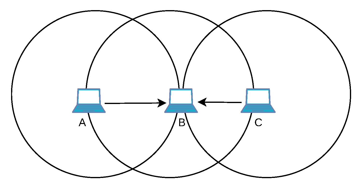
5.2. Challenges with SR in Legacy Wi-Fi

With SR, different BSSs utilize the same channel via the CSMA/CA protocol. When BSSs overlap and use overlapping channels, they cause more collisions [110] and a poor data rate. This leads to problems with legacy Wi-Fi that we illustrate in the following figure Figure 13.
The NAV is a timer that helps to block stations during an ongoing transmission. The backoff is paused during the NAV, forbidding the competing stations to start their transmission. In legacy Wi-Fi, only a single NAV exists and is updated after overhearing any transmissions. Thus, it may cause collisions if two different BSSs have parallel transmissions with different durations. A node may be a neighbor of the two transmitters that belong to two different BSSs. This neighbor will overhear the first RTS/CTS reservation and update its NAV. Then, the same neighbor will overhear the second RTS/CTS from the second BSS and will overwrite the existing NAV with those contained in the new RTS. If the second NAV value is short enough, the neighbor may create a collision since it will consider erroneously that the medium has been released.
If a station receives an RTS with a weak signal strength, the sender is far away from the receiver station. Then, the upcoming transmission will not be impaired by a potential transmission of the receiver. In that case, setting the NAV by the receiver station is not needed. This unnecessarily prevents the receiver station from sending, which is a waste of transmission resources.

5.3. Mechanisms for Spatial Reuse in Wi-Fi 6

Wi-Fi 6 exploits BSS coloring to differentiate traffic from different BSSs. Intra- and inter-BSS NAVs avoid erroneous NAV resets that cause collisions. Further mechanisms facilitate simultaneous transmissions on a channel by different BSSs.

5.3.1. BSS Coloring

BSS coloring [111] is an inherited feature from IEEE 802.11ah to distinguish traffic from different BSSs. It is a 6-bit field in the novel frame preamble [112]. The access points operating on the same channel should have different BSS colors. A station uses the BSS color in the preamble to make a distinction between intra- and inter-BSS transmissions.

5.3.2. Intra- and Inter-BSS NAV

The standard proposes that a station utilizes distinct NAVs for different BSSs. A station updates its NAV value independently for each BSS color whenever a NAV value is read in a frame and when a Cf-end frame is received. A station can transmit a frame only if all its NAV values are equal to zero, preventing collisions. However, most devices and research papers approximate BSS-specific NAVs with one intra-BSS NAV and one inter-BSS NAV [113].

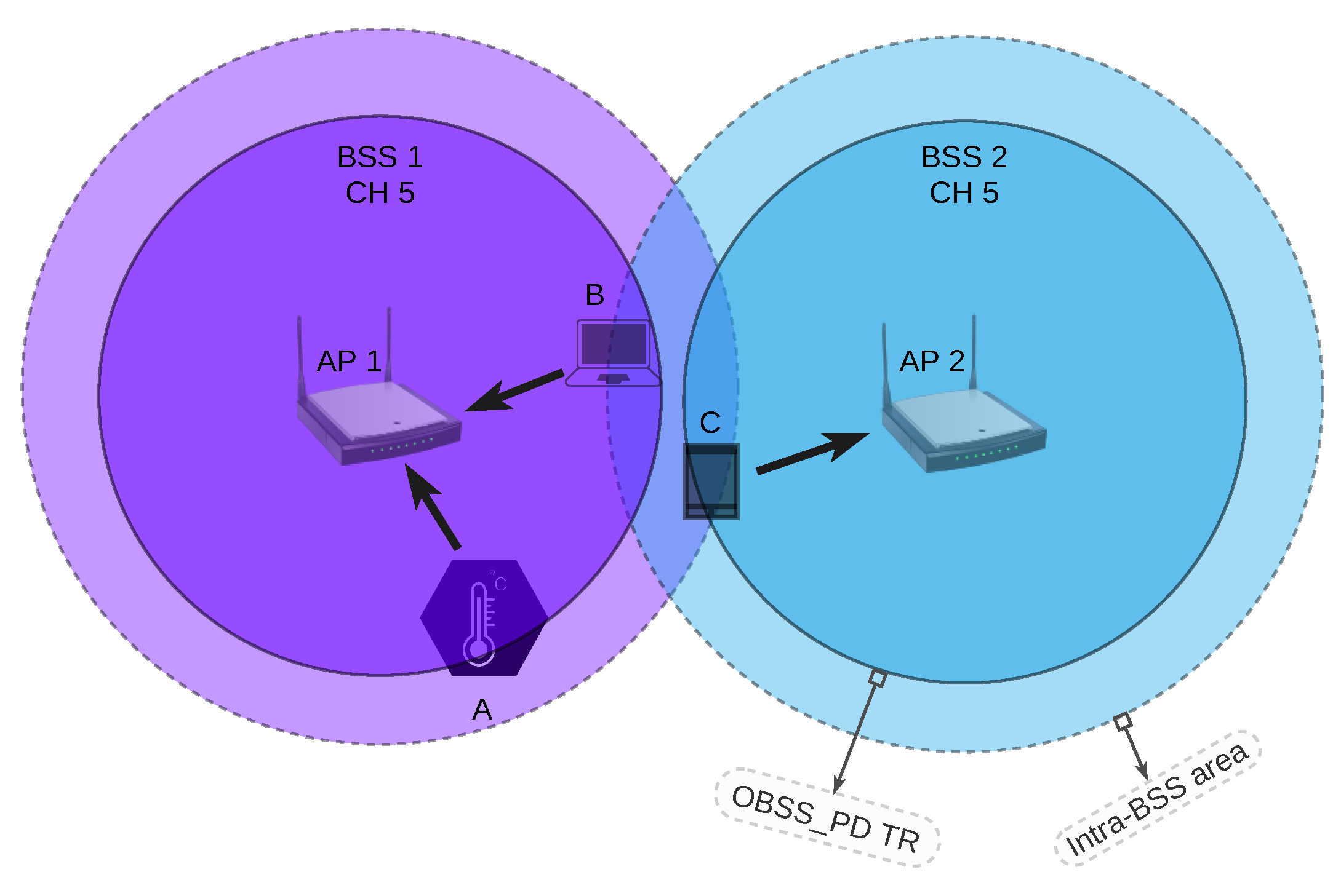
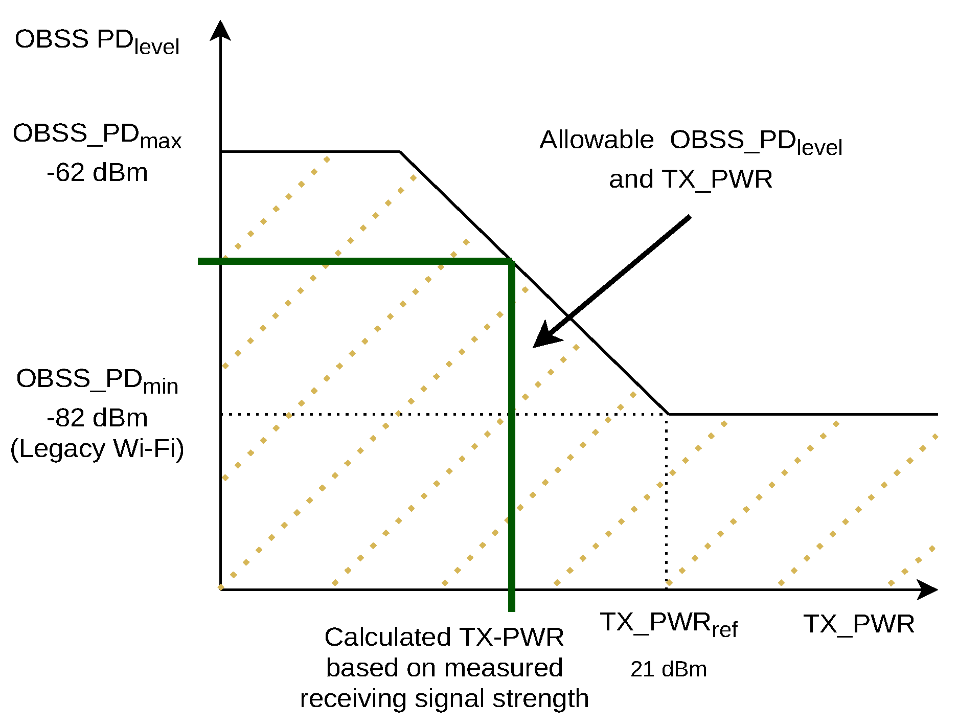
5.3.3. Overlapping BSS Packet Detection (OBSS PD)

With Overlapping Basic Service Set Packet Detect (OBSS PD), nodes can disregard inter-BSS traffic received with a low signal strength. To improve the overall throughput, a novel Clear Channel Assessment (CCA) threshold is defined for inter-BSS traffic called the O B S S _ P D l e v e l . If a station receives an inter-BSS frame, it updates its inter-BSS NAV only if the sensed RSSI is larger than the O B S S _ P D l e v e l .
The O B S S _ P D l e v e l and T X _ P W R as the transmission power of a station have an inverse relationship. Thus, a higher O B S S _ P D l e v e l implies a lower T X _ P W R to avoid interference with transmissions in other BSSs. The value for the O B S S _ P D l e v e l is in the range of O B S S _ P D m i n = −82 dBm, which corresponds to the normal CCA threshold and O B S S _ P D m a x = −62 dBm [5,12]. The transmission power T X _ P W R is calculated using the following equation:
T X _ P W R = T X _ P W R r e f ( O B S S _ P D l e v e l O B S S _ P D m i n )
In other words, a large O B S S _ P D l e v e l allows a node to overhear inter-BSS traffic with a low signal strength. Moreover, the mechanism permits a station to start transmission in the presence of inter-BSS traffic if it reduces the transmission power of its own signal.
Differentiated OBSS PD treatment of inter-BSS traffic may be helpful if some of them are close and others are further away. To that end, OBSS PD has been extended with spatial reuse groups (SRGs). One SRG is a set of BSSs for which specific OBSS PD parameters are defined [12]. Finally, we have:
  • CCA parameters for intra-BSS traffic;
  • OBSS PD parameters for inter-BSS traffic that is part of the same spatial reuse group;
  • General OBSS PD parameters for the remaining inter-BSS traffic.

5.3.4. Parameterized Spatial Reuse (PSR)

Parameterized Spatial Reuse (PSR) is an alternative adaptive approach to support more concurrent transmissions. Each access point embeds its tolerable interference level and its transmission power within the Trigger Frames (TFs) to inform overlapping BSSs about concurrent uplink transmissions [98]. The maximum interference level depends on the RSSI, the minimum SNR of the highest MCS, and a safety margin. It is computed in a way that interfering signals with this strength at the most do not impair the reception of valid signals. Receiving stations measure the RSSI and use the transmission power coded in the frame to compute the loss in signal strength. The maximum interference level and this loss of signal strength propose a maximum value for the receiving station’s transmission power. The station must apply a transmission power below the proposed values for all neighboring access points. This mechanism may lead to low transmission power, low MCS, and longer data transmission.

5.4. Related Works

In this section, we categorize the related works in SR concerning threshold manipulation, MAC modification, rate control, and performance evaluation.

5.4.1. Threshold Manipulation

The efficiency of SR increases by increasing the carrier-sensing threshold value. However, decreasing the value causes the hidden node problem, which may be symmetric or asymmetric. In the symmetrical hidden node problem, station A does not trigger station B’s carrier sense threshold and accordingly, B cannot hear from A. This causes repetitive collisions among these two stations. The asymmetric hidden node problem means that station A is located out of the carrier sense range of station B but station A can hear station B. Thus, B causes collisions for the packets of A while A lets some packets from B be received. Then, the backoff value will increase more frequently for A than for B. The asymmetric hidden node problem can happen in both inter- and intra-BSSs causing severe unfairness among stations [114]. The problem is handled by different parameter values (transmission power, etc.).
The following papers focused on resolving the hidden node problem. Controlling the threshold or applying RTS/CTS help to reduce the hidden terminal problem [114]. The impact of hidden nodes on the uplink transmissions in the presence of legacy Wi-Fi and Wi-Fi 6 stations was investigated in [115,116]. They proposed three possible solutions: (1) increasing the threshold of all stations in the association phase with an HE access point; (2) specifying different channels for adjacent BSSs; (3) the NAV of a station could only be set if an intra-BSS station is transmitting data. Sou et al. [117] proposed a trigger-based approach for uplink multi-user transmissions. The access point sends a multi-user RTS. If some stations do not respond because they have a non-zero NAV (i.e., they are hidden nodes), other stations not in the trigger list can respond with a CTS if they have a zero NAV.
Some other works focused on optimal CCA threshold tuning. Dynamic Sensitivity Control (DSC) [118,119] tunes the carrier sense threshold of the access point according to the RSSI of the farest station to transmit more data concurrently. This means that the access point tunes the value based on the worst case. The performance of DSC was examined in [120] where DSC with a well-tuned margin for threshold outperformed legacy mechanisms in throughput. Nonetheless, it also depends on the node density and topology. The fairness in medium access also depends on the margin. Since DSC causes a hidden node problem, [121] combined it with RTS/CTS. The authors of [122] leveraged DSC and TDMA mechanisms jointly to solve the hidden node problem. They proposed to reserve multiple stations or one BSS within a time interval to have timely orthogonal BSSs. Yan et al. [123] bound the CCA threshold value in the PSR mechanism, which manages parallel link interference, to improve QoS. The authors in [124,125] leveraged stochastic geometry in carrier-sensing threshold manipulation. Every access point tunes the carrier-sensing threshold and transmission power based on its received power. They concluded that a linear increase in the carrier-sensing threshold with respect to the received power maximizes the throughput. Kiryanov et al. [126] extended [127] to reduce memory usage and converge faster, which applied a branch-and-bound method to optimize the transmission power and scheduling. The utility function is a function of the thermal noise, transmission power, and channel gain, i.e., a factor of sent and received signals and noises that includes the effects of path loss, shadowing, and fading. They tried to find the right value for the carrier-sense threshold. A dynamic resource scheduling regularly runs the mechanism to consider prior radio resources per user for optimal resource allocation.
Wilhelmi et al. [128] aimed to reduce interference and improve SR with a dynamic channel allocation and by controlling the transmission power, respectively. They applied multi-armed bandits to find the optimal combination of transmission power and channel to enhance throughput. Bardou et al. [129] also adopted a multi-armed bandit approach for the same objective. They proposed a Gaussian mixture to sample new network configurations and computed a reward to avoid starvation to select the best configuration. NS-3 simulations validated the model.
Some papers aimed to compute the OBSS PD value efficiently. The authors of [130] exploited the RSSI of the beacon to directly compute the OBSS PD threshold. The transmission power is calculated by subtracting a value from a beacon’s RSSI. A station close to the access point will use a large OBSS PD value. Selinis et al. [131] proposed a Control OBSS PD Sensitivity Threshold (COST) algorithm. First, the access point collects the moving average of the stations’ RSSIs and the interference levels from all the stations. Then, it derives the sensitivity threshold value to respect a minimum margin.
The OBSS PD value may directly affect the network throughput. Interference-Based Dynamic Channel Access (IB-DCA) [132] maximized the aggregate throughput of the WLAN. Each station keeps a record of the maximum RSSI level of all the overlapping BSSs, i.e., BSSs with a different color. More precisely, it measures the maximum RSSI separately for uplink and downlink transmissions. These values are advertised to other stations periodically as well as the transmission power of the issuer. Thus, any station can compute the expected RSSI level at the expected destination based on these values. The station defines its SR flag accordingly; it knows it will not provoke any collisions since the expected receiving RSSI will be sufficient to be robust against transmissions in overlapping BSSs. As an extension, the authors of [133] focused on the performance of each end-user in dense networks. Lanante et al. [134] proposed an analytical model to find the suitable OBSS PD threshold and transmission power that optimizes the throughput. They proved that the throughput depends on the interference range of the BSSs. The model was based on the received power, transmission power, MCS, distance, and path loss. The authors of [135] improved the aggregated throughput by tuning the OBSS PD threshold and transmission power. They utilized the RSSIs of beacons and overlapping BSSs. The former keeps the connection with the access point and the latter prevents interference in overlapping BSSs. The threshold is computed based on the recorded RSSIs and uses an exponentially weighted moving average (EWMA) [136] for updating the threshold during runtime. Lee et al. [137] proposed a link-aware SR algorithm to select the appropriate links for simultaneous transmissions and the MCS without interfering with the ongoing transmission. The mechanism tunes the transmission power for transmission protection and applies EWMA to select the link and MCS that compute the achievable throughput.
A distributed OBSS PD mechanism was proposed to improve the fairness in the network [138]. Taking into account the history of transmission opportunities, it tunes the OBSS PD threshold. It prioritizes stations that did not access the medium in earlier time slots and downgrades the other stations.

5.4.2. MAC Modifications

Kwon et al. [139,140] focused on the stations whose transmissions are blocked because of multiple inter-NAVs sets. The station is idle for a wait threshold and then selects one of the neighboring access points with a lower latency and a higher-quality transmission. It then beamforms the data in that direction.
An interference-aware MAC queue in downlink transmissions was proposed in [141] to handle the interference level caused by BSS coloring. The access point selects the packet from the queue based on the interference severity, remaining transmission duration, and fairness factor. The stations are classified into three categories based on their RSSI: short distance, intermediate distance, and edge nodes. The access point selects the recipient station depending on the inter-BSS RSSI strength.

5.4.3. Rate Control

The authors of [142] introduced two control mechanisms to improve the capacity and network throughput. The first approach transfers low-transmission-rate stations of a BSS to the cellular networks. The latter clusters BSSs with negligible mutual interference together to maximize the throughput. Afterward, clusters apply round-robin scheduling in uplink OFDMA.
Damysus [143] is a decentralized rate-control algorithm exploiting BSS coloring. It adjusts the rate relying on packet loss ratio thresholds. Based on the loss ratio thresholds, it tunes the rate, the OBSS PD threshold, and the transmission power with an approach similar to the one in [131].

5.4.4. Performance Evaluation

Most of the evaluations were conducted with a network simulator. Shen et al. [144] developed a simulator in NS-2 to evaluate the OBSS PD mechanism and throughput of each BSS. They showed that the SR improves performance by 34%.
Selinis et al. [145] evaluated the Dynamic Sensitivity Control (DSC) and BSS coloring mechanisms with NS-3 simulations. They observed that DSC improves the network throughput and preserves fairness among the stations. Moreover, BSS coloring improves the network performance if the number of Wi-Fi 6 stations is larger than legacy stations. Selinis et al. [146] analyzed dynamic sensitivity control and BSS coloring with the same simulator while the network was modeled by the capture effect model. They highlighted that the throughput improves with larger frame sizes, whereas the high data rate and large frame size negatively affect the throughput. SR’s throughput was analyzed in [147] in NS-3. They reached the conclusion that SR performance depends on the CCA threshold, power, and the distance between the BSSs.
Wilhelmi et al. [148] evaluated the SR mechanisms with the Komondor simulator. They considered up to 400 scenarios by varying the number of stations, topology, OBSS PD threshold, and traffic load. Its efficiency is measured by throughput, delay, and channel occupancy. By alleviating the inter-neighbor WLAN’ contentions successfully, SR reveals its significance in high-density and high-load networks.
The authors of [21] evaluated the BSS color efficiency also with NS-3. They proved that BSS coloring increases the throughput per access point up to 47%. Šepić et al. [149] mainly focused on BSS color. Seven BSSs were simulated with 70 stations and various threshold values were applied to find the optimal value. They concluded that up to a certain value, the throughput increases and thereafter the performance degrades because of the interference from other BSSs.
Rodrigues et al. [150] investigated the impact of the PSR! (PSR!) feature on transmission latency using a testbed. The evaluations revealed that this feature could reduce the latency considerably in worst-case scenarios and enhance the throughput.

6. TWT in Wi-Fi 6

We first explain the challenges for power saving with legacy Wi-Fi. Then, we present the TWT mechanism and other power management improvements in Wi-Fi 6. Finally, we review the related works in the context of power management.

6.1. Challenges with Power Saving in Legacy Wi-Fi

Although the PSM mechanism (see Section 2.2.3) saves energy, stations must wake up regularly to receive beacons (more precisely, one beacon at every DTIM interval). Moreover, stations with a pending packet must stay awake until they have sent it. If a station has multiple packets to send, it cannot sleep until its buffer is empty. These limits affect the energy consumption [22].

6.2. Target Wake Time (TWT) Mechanism in Wi-Fi 6

We first give an overview of TWT and then explain its basic operation, agreements, and operation modes.

6.2.1. Overview

The TWT was introduced in 802.11ah [23]. It has been adopted by Wi-Fi 6 to reduce energy consumption and solve contention issues. TWT aims to introduce a deterministic and collision-free wireless network. It reduces the latency and queue occupancy by utilizing multi-user transmissions and packet aggregation. In addition, the idle time of the stations increases, which considerably reduces energy consumption [13]. TheTWT balances the load with different TWT sessions for different stations. It also decreases the medium access contention by frame exchanges in advance. The standard does not specify a default scheduling for the TWT and is manufacturer-specific.

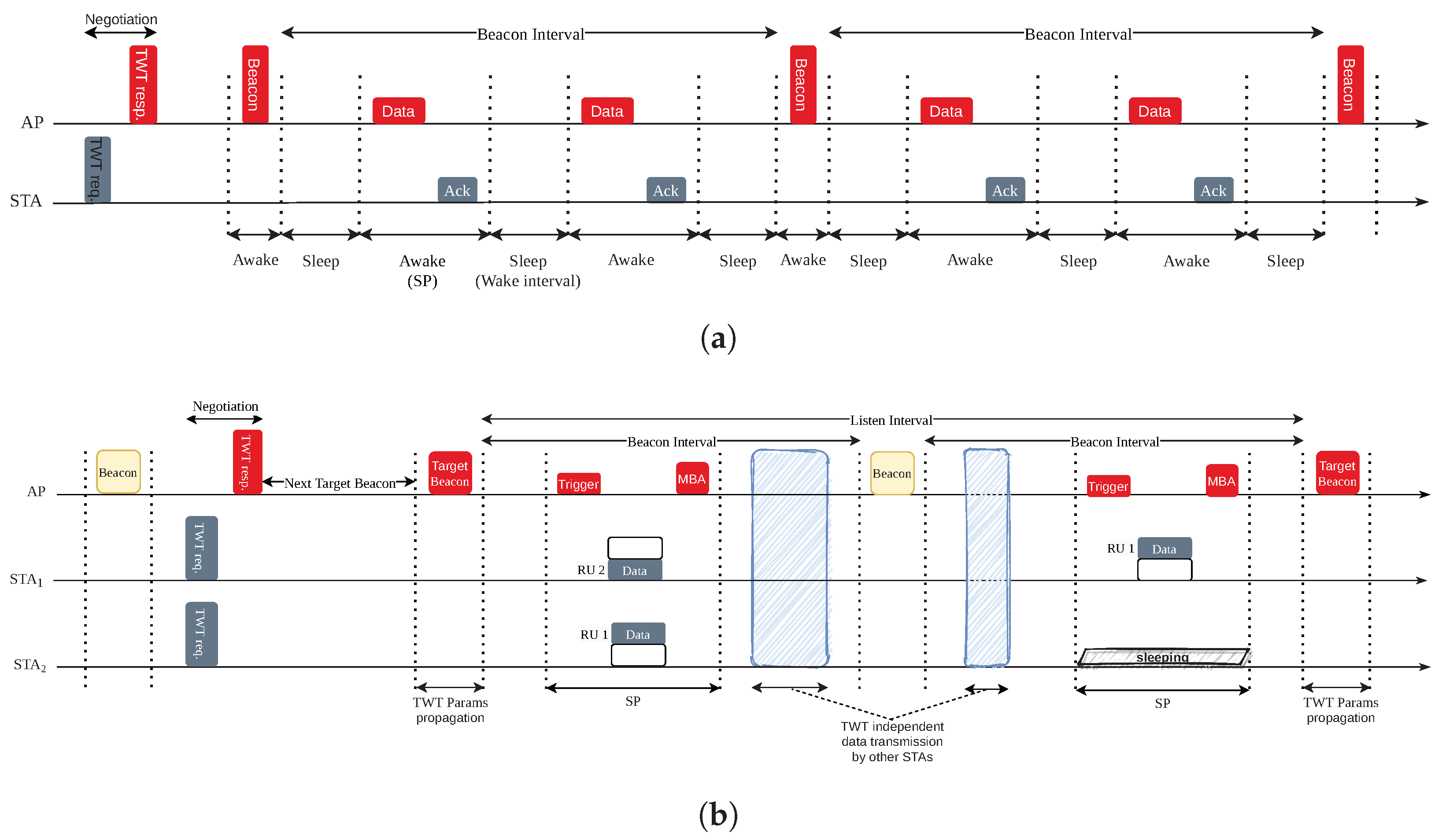
6.2.2. Basic Operation

The stations negotiate their communication needs with the access point. The access point then acts as a central controller and schedules activity and inactivity periods for stations during which they may transmit/receive or sleep. These times are called service periods (SPs) and wake intervals. The SPs are also denoted as TWT sessions. Wake intervals can be longer than beacon intervals, which solves the first problem mentioned in Section 6.1. The stations with data to send can sleep until the next SP, which solves the second mentioned problem. Moreover, assigning the SPs to the stations greatly reduces contention issues within a BSS. Within the SPs, the stations can exchange data and control packets. If a station has more urgent data to send, it can also transmit data during the wake intervals using the normal DCF procedure.
The negotiations define the duration of the SPs (TWT duration), which are multiples of either 256 μ s or 1024 μ s, and the duration of the wake intervals. A TWT channel is a temporary channel, e.g., an RU that a station can use as the primary channel. Finally, TWT protection is defined to protect an SP from external transmissions. An example is the use of RTS/CTS at the beginning of an SP.

6.2.3. Agreements

Negotiation results are so-called TWT agreements. A station can have up to eight agreements with its access point [5]. This is useful to cover traffic from different applications with distinct agreements. Individual agreements assign resources to an individual station, whereas broadcast agreements assign resources to a group of stations.

Individual Agreements

Individual agreements are negotiated between a single station and its access point. Both can cancel the agreement. Figure 14a illustrates the use of an individual agreement. For the negotiation, the station sends a TWT request and the access point replies with a TWT response. The schedule is defined by the TWT parameters that are provided within the next beacon frame. The station must be awake to receive this beacon frame but it can sleep as soon as the TWT schedule is decoded from the beacon. The station is awake within the SPs to transmit or receive frames to or from its access point. This procedure may repeat for a longer time than a beacon interval depending on the agreement or terminate within the same beacon interval.

Broadcast Agreements

Wi-Fi 6 has enhanced the original TWT mechanism to also consider broadcast agreements. A broadcast TWT corresponds to an SP for a group of stations. These agreements avoid duplicating broadcast or multicast packets that have to be delivered to several stations. Indeed, all the stations have to stay awake to receive broadcast frames.
In contrast to the individual agreements, the parameters for the TWT sessions are not provided in normal beacon frames but in so-called target beacons. After having transmitted their request, the corresponding stations can sleep until the next target beacon. Target beacons are sent periodically every listen interval and contain the schedule for all the TWT sessions. A listen interval may contain multiple SPs corresponding to different groups of stations. The stations participating in the TWT agreements must wake up for the target beacons as there might be updates for the parameters.
Figure 14b illustrates the operation with a broadcast agreement. All the stations can send their requests to their access point just after the beacon. Thus, the access point collects the TWT requests and sends a TWT response, announcing when the next target beacon will be transmitted. All the stations decode it and can sleep until the next target beacon. The stations decode the different SPs assigned by the access point in the target beacon. Then, they have to wake up for the service period (SP) they have been assigned to. Here, both stations 1 and 2 participate in the first SP, whereas only station 1 is involved in the second one.

6.2.4. TWT Operation Modes

There are multiple modes for TWT agreements, which we exemplify in the following subsections.

Implicit vs. Explicit Mode

The service periods (SPs) in this agreement can be implicit or explicit, which are also called periodic or aperiodic. In the implicit agreement, the successor SPs apply the same parameters as the first SP [5]. Explicit agreements require a new set of TWT parameters for the next SP.

Announced vs. Unannounced Mode

In announced mode, a station indicates to the access point that it is ready to receive buffered data. Only then does the access point send data to the station. Conversely, in unannounced mode, the access point assumes that the corresponding stations are awake in the SPs and immediately sends data to them. Announced mode is more efficient for saving energy when a station has a very small amount of frames to receive.

Trigger-Enabled vs. Non-Trigger-Enabled Mode

In trigger-enabled mode, the access point sends a TF at the beginning of an SP and schedules the transmissions for the stations participating in this TWT session. Thus, it limits the number of collisions. In non-trigger-enabled mode, the stations decide when to start the transmission without any negotiation with the access point.

6.2.5. Multi-User TWT

TWT leverages the multi-user feature of OFDMA in Wi-Fi 6 to maximize efficiency. The multi-user operation mode reduces the overhead of the control packet and makes packet aggregation viable [13]. The access point may assign different RUs to the stations in an SP. Multiple stations wake up synchronously within one SP and the BSS can multiplex the transmissions over different RUs. Thereby, the access point maximizes energy efficiency by limiting idle listening without impacting network capacity. Moreover, multiple Target Wake Times (TWTs) may be scheduled in parallel on different RUs in a single TXOP, providing more freedom in scheduling.

6.3. Additional Improvements

Access points of overlapping BSSs may cooperate to avoid collisions. Typically, they may allocate different RUs within their BSSs or they may schedule SPs sequentially.
A station participating in a TWT session should stay awake during SPs. With Intra-PPDU Power Save, a station can temporarily sleep within an SP if it receives a frame from the same BSS and if this frame is not relevant to it. This means that the station sets its NAV timer, turns to sleep mode, and wakes up only at the end of the current PPDU [5,111].
Opportunistic Power Save (OPS) removes the obligation to negotiate the SPs, combining the classic PSM and the novel TWT broadcast agreements [5]. It divides the beacon interval into sub-intervals. The access point schedules a broadcast SP in every sub-interval and tells certain stations to stay awake and transmit or receive data. The system does not need explicit negotiations; the schedule is propagated by a traffic indication map frame at the beginning of every broadcast SP. The stations receive this frame and if they have no activity in the current SP, they turn to sleep mode until the next SP. Thus, OPS reduces the overheads of the SPs’ negotiations, which may be costly in dense networks. In addition, the access point assigns different stations to independent sub-intervals, making the system more efficient through load balancing [5].

6.4. Related Works

Proper scheduling of the stations and user distribution among the wake times are vital in TWT. Here, we review the related works in terms of user distribution, clock drifts, and traffic aware scheduling.

6.4.1. User Distribution

Distributing the stations to different TWT SPs helps to minimize the collision in the network. Bai et al. [151] proposed an uplink OFDMA random access grouping scheme by utilizing the TWT feature to minimize the collision rate in random access mode. The objective was to maximize performance by optimizing the group size of the stations within one TWT SP. Stations are distributed in different SPs and a random access process takes place in each of them. If too many stations compete, they will create collisions. Conversely, a small group may reduce network capacity, the transmissions being inefficiently multiplexed. The adaptive algorithm considered lower and upper bound grouping sizes and group stations to achieve the highest system efficiency.
The authors of [152,153] planned random access uplink scheduling to minimize contention and, thereby, power consumption. The access point accepts or rejects the TWT requests using a mathematical model based on the number of stations, the RUs, and the listen intervals. In particular, stations that wake up at the same time would collide. Therefore, the access point will schedule them in separated TWT sessions to reduce the collision probability.
Chen et al. [154] avoided collisions by limiting the number of selected stations to wake up in every target beacon close to the number of available RUs. They derived a throughput optimization problem with delay and instant throughput constraints. They solved the problem using a genetic algorithm and the outcome was the optimal listen interval schedule for TWT broadcast agreements.
The authors of [155] applied max-rate and proportional fairness scheduling to the TWT mechanism in order to maximize throughput, save energy, and improve fairness. Max-rate scheduling divides the nodes into two groups and assigns them to two timeslots within an SP. Proportional fairness scheduling selects the appropriate station at the beginning of each timeslot.

6.4.2. Clock Drifts

The clock drift impact on scheduling is a major problem with TWT [156]. Since a station can sleep for a long time, time errors due to clock drifts accumulate, and the TWT sessions have to be carefully scheduled to avoid collisions. In trigger-enabled mode, a station must wake up before the expected trigger frame arrival, i.e., twice the maximum clock drift. Alternatively, the TWT sessions should be sufficiently inter-spaced to deal with the longest clock drift.

6.4.3. Traffic Aware Scheduling

The following works focused on saving energy. A pending notification scheme for uplink multi-user transmissions was introduced in [157]. A flag is added in the frame header to notify the access point that more frames need to be transmitted. Thus, an access point can automatically allocate more transmission opportunities to the station with pending frames without needing an explicit and costly renegotiation. This method is particularly efficient for bursty traffic. Karaca et al. [158] utilized multi-user scheduling and an individual TWT agreement to save energy. They formulated a stochastic optimization problem considering the traffic status of the stations. Then, they applied the Lyapunov optimization function and concluded that high energy saving is achievable by larger average queuing delays. The solution to lower the average queue delay updates the TWT intervals more frequently, which causes more signaling overheads.
Some works considered the traffic to tune the wake times of the stations. The authors of [159] considered joint multi-user scheduling and a TWT interval assignment as a stochastic optimization problem. They took into account the load of every station and solved it using a Lyapunov optimization framework. The suggested mechanism dynamically assigns the TWT intervals to stations regarding the channel conditions and their traffic. Qiu et al. [160] detected the traffic type using machine learning techniques. Then, they determined the wake intervals for the stations by taking into account the runtime throughput and expected latency for the specific traffic type.

7. Multi-User Multiple-Input Multiple-Output (MU-MIMO)

In this section, we describe MU MIMO technology in Wi-Fi 6 and review the related works.

7.1. MU MIMO in Wi-Fi 6

Wi-Fi 6 supports uplink and downlink MU MIMO. A combination of OFDMA and MU MIMO is also possible. Downlink MU MIMO enables an access point to send data to multiple stations at the same time. The new standard improves Wi-Fi 5 to support up to eight downlink spatial streams. The access point can serve multiple stations that have fewer antennas, e.g., an access point with eight antennas is capable of serving up to four stations with two antennas. The access point periodically learns the target stations’ locations using channel sounding and then directly beamforms the data toward the destination. It transmits the data using the HE MU PPDU format (see Section 4.1.4).
Uplink MU MIMO is a newly added feature in Wi-Fi 6 to support high-bitrate applications and content streaming. It exploits MIMO systems to allow up to eight stations to transmit frames simultaneously to the same access point. Similar to uplink OFDMA, the access point initiates the transmission by a Trigger Frame (TF). Then, the stations transmit data in the HE TB PPDU format (see Section 4.1.4).

7.2. Related Works

We review the related works concerning user selection, channel estimation, and performance evaluation in MU MIMO.

7.2.1. User Selection

The access point must select the stations that can transmit simultaneously in UL MIMO. MUSE [161] improved the throughput by selecting the most accurate set of transmitters in the uplink. Primarily, the access point initiates an uplink OFDMA transmission and records the Channel State Information (CSI) from each station. Regarding the obtained information, the access point selects the optimal set of users for MU MIMO. MUSE proposed to use EDCA to reduce the number of collisions when sending the CSI.
The authors of [162] applied reinforcement learning techniques for efficient MU MIMO user selection. They considered a Software-Defined Networking (SDN) controller in charge of the learning process that monitors the network to reduce the volume of control packets compared with a distributed monitoring process. The requests from stations are forwarded to the controller, which decides how to allocate resources and configure the link parameters dynamically depending on the load.
Oni et al. [163] formulated a throughput maximization problem in MIMO WLAN. They mitigated the hidden node problem by optimizing the CCA threshold. Finally, they maximized the average number of successful transmissions with respect to the density of nodes, multi-antenna configuration, channel fading, and path loss.
Kim et al. [67] proposed a new MU MIMO frame format in both uplink and downlink to maximize the transmission efficiency. They formulated the problem as NP-complete and considered the status of the buffer and the bitrate of the stations. They solved the problem to find the optimal length of the multi-user frame.

7.2.2. Channel Estimation

Estimating the wireless channel is especially important in MIMO. An access point should minimize interference level among contending stations.
Hoefel [164] mitigated the carrier frequency offset (CFO) in an uplink MU MIMO that causes inter-carrier interference and rotation of the constellation of the received symbols. He first modeled the received signal for the OFDM uplink MU MIMO channel. Then, he derived a minimum mean squared error for MU MIMO receivers to estimate the channel. The results revealed that the frequency domain CFO estimation reimburses the relative CFO effect in the uplink MU MIMO channels.
The same author [165] highlighted that the phase noise hardware impairment does not degrade performance even when the received powers from different MIMO transmitters differ. The in-phase and quadrature (IQ) imbalances have a much stronger impact. Due to non-ideal hardware, modulators and demodulators may cause errors, possibly increasing the Packet Error Rate (PER). In particular, the carrier frequency offset may have a non-negligible impact for uplink MIMO [166]. Thus, the channel needs to be finely estimated to mitigate both the amplitude and the phase imbalance.
In MIMO, beamforming has a strong impact on the PER; the transmitter must select which signal to transmit for each of its antennas and for each subcarrier. Jeon et al. [167] proposed adaptive feedback from the receiver to adjust the beamforming matrix. Nabetani et al. [168] proposed a new channel sounding scheme, i.e., a technique to measure the properties of the radio channel, particularly for the multipath effect, to improve the throughput in downlink MU MIMO and reduce the overhead. Stations feed back the compressed beamforming frames concurrently using uplink multiplexing. The access point reduces the latency to collect the CSI and thus decreases the bandwidth consumption.
The authors of [169] proposed a deep learning model for a joint downlink MU MIMO and MU OFDMA to improve throughput and reduce the channel-sounding overhead. A deep neural network leverages uplink Channel State Informations (CSIs) to train for the downlink transmission. They also considered resource allocation as a mixed-integer nonlinear programming optimization problem. Then, they employed a deep neural network to this problem for near-optimal resource allocation.
Zheng et al. [170] introduced a newPHY design for an asynchronous uplink MU MIMO. The access point receives concurrent signals asynchronously from multiple stations. While it is decoding a signal, it considers the other incoming signals as interference. It then applies a spatial filter to recover this signal. This mechanism works properly for up to four users.

7.2.3. Performance Evaluation

The authors of [171] observed the behavior of random access considering different MU MIMO sizes and frame aggregations over different channel widths. They concluded that the collision probability is lower with a large contention window. Fewer retransmissions are required and it saves energy. The counterpart is a reduction of the network capacity when the number of contending stations is insufficient to saturate the medium.
Qu et al. [15] considered indoor/outdoor and single/multiple BSSs. The simulations revealed that using MU MIMO increases the throughput in OFDMA. They concluded that Wi-Fi 6 gains more when the bandwidth increases. Downlink transmissions also impose a lower overhead than uplink transmissions. The authors of [102] developed a light simulator to evaluate MU MIMO. Uplink MU MIMO performance improvement has an inverse relationship with the number of contending stations. Therefore, transmitting data in a scheduled manner avoids degrading the throughput.
Heo et al. [172] compared SU MIMO and MU MIMO in terms of latency and throughput. They reported that MU MIMO improves the latency, throughput, and collision probability. They also expressed that MU MIMO improvements in WLAN are not as effective as in cellular networks.
Hoefel [173] concluded that dynamic scheduling helps to improve the throughput. He analyzed the channel sounding for uplink and downlink MU MIMO. The analysis included the impact of in-phase and quadrature (IQ) imbalances, channel-sounding compression modes with phase noise, and carrier frequency offset.

8. Modulation Techniques

This section introduces the new modulation schemes in Wi-Fi 6. Then, we elaborate on other modulation improvements, namely, DCM and LDPC. Finally, we discuss the related works.

8.1. Two New MCSs in Wi-Fi 6

The new modulation, 1024-QAM (10 bits per symbol), increases data rates by up to 25% compared with Wi-Fi 5. Wi-Fi 6 supports BPSK, QPSK, 16-QAM, 64-QAM, 256-QAM, and 1024-QAM modulations [5]. The new MCS 10 and 11 with 1024-QAM modulation operate with 3/4 and 5/6 coding rates, respectively. The selection of the right MCS heavily depends on the channel quality that can be measured by the packet loss ratio, SNR, bit error rate, transmission time, throughput, transmission statistics, or a combination of these metrics. The higher the SNR, the higher the MCS index that could be applied, which results in data rates of up to 9.6 Gb/s [5]. The nominal data rate can be formulated formally as follows:
D a t a R a t e = N s u b c a r r i e r · N S S · N b i t s · C R T P + T G I
where N s u b c a r r i e r is the number of data subcarriers, N S S is the number of spatial streams, N b i t s is the number of bits per OFDM symbol, C R is the coding rate, T P is the OFDM payload symbol duration, and T G I is the guard interval duration. Table 4 lists all available MCS and their data rates for a single spatial stream.

8.2. Dual Carrier Modulation (DCM)

Dual Carrier Modulation (DCM) was first used in IEEE 802.11ad and aimed to improve long-distance transmissions [174]. This modulation duplicates the same information on two different subcarriers at two different channel frequencies separated far apart in terms of frequency. The modulation in both subcarriers is similar. Therefore, it brings frequency diversity for OFDM. On the receiver side, demodulation is performed by a Log Likelihood Ratio (LLR) demapper that receives the two DCM symbols. It increases signal resiliency and deals with narrow-band interference in Wi-Fi 6. Therefore, DCM is recommended for MCS 0-4 [24].

8.3. Forward Error Correction (FEC)

Forward Error Correction (FEC) helps a receiver to detect and possibly correct transmission errors. The source inserts redundancy in its transmission so that the receiver can detect the erroneous symbols and ideally correct them. More precisely, convolution codes encode m bits of information into an n bit symbol. Obviously, n is larger than m, and a larger difference increases the robustness. Each MAC protocol data unit is processed independently and a transmission failure means that the corresponding frame has to be retransmitted entirely.
Binary Convolution Codes (BCC) and Low-Density Parity Check (LDPC) are two FECs used to reduce the probability of data loss in noisy channels. BCCs support up to a 242-tone RU. Alternatively, LDPC is applicable in Wi-Fi 6 for MCS 10-11 and/or RU sizes larger than 242-tone [175,176]. In other words, a BCC is mandatory for bandwidths smaller than or equal to 20 MHz; otherwise, LDPC is used for larger bandwidths. Indeed, a BCC is inefficient for large bandwidths, requiring more time to process data and more encoders [177].

8.4. Related Works

In this section, we review the related works concerning MCS selection and performance evaluation.

8.4.1. MCS Selection

An access point must select the most accurate MCS for each station. A higher MCS means a larger throughput if the radio link is strong enough. Otherwise, the bit error rate begins to dominate and will corrupt most of the frames. However, the standard does not propose any mechanisms to select the most appropriate one.
Adame et al. [178] proposed a new path loss model for 5 GHz indoor environments. They showed that when using low bandwidth and high transmission power for transmission, the access point gain increases by choosing a higher MCS. Moreover, as the RSSI increases, the number of used spatial streams also increases. Krotov et al. [179] took into account the interference and noise level. A station estimates the channel quality according to the successful transmissions using a particle filter [180]. Then, with respect to the channel quality, the station selects the best-fitted MCS to achieve higher reliability and performance.
Hussien et al. [181] proposed a deep learning approach to select the best MCS. Link adaptation was modeled as a multi-label multi-class classification and predicted the performance of the system for both the optimal MCS and suboptimal MCS. They applied a deep convolutional neural network to predict the performance with a dataset generated with Matlab. The loss function gives a larger penalty for false positives; the MCS should not have been selected since it jeopardizes the reliability.
An access point may have precise knowledge of the CSI of each station and should allocate an RU and MCS to each of them. This scenario corresponds to an optimization problem. Ha et al. [182] proposed a mixed-integer nonlinear programming formulation to maximize the total system throughput. They assumed that there was a specific Bit Error Rate (BER) model per MCS. A station may also be attached to multiple access points, which makes the link adaptation more challenging [183].

8.4.2. Performance Evaluation

Sharon et al. [184] compared the throughput of Wi-Fi 6 and Wi-Fi 5 over MCS 0–11 with different MPDU sizes. They revealed that over small MCS, different MPDU sizes do not affect the throughput. As the MCS index increases, the larger MPDU sizes provide higher throughput. Moreover, Wi-Fi 6 outperforms Wi-Fi 5 by up to two times in throughput. Sanchez et al. [185] deployed an IEEE 802.11g Wi-Fi network that comprised one station and one access point. They compared these experimental measurements with simulations using the default Wi-Fi 6 package available in NS-3 to quantify the effectiveness of the novel MCS. More precisely, they emulated the wireless link from the station to the access point using the delay measured in the real deployment. However, this paper did not explain the implementation in detail, namely, thePHY model.
The authors of [186] evaluated the performance at the application layer in a testbed. They revealed that Wi-Fi 6 provides better channel utilization and higher throughput than Wi-Fi 5. This channel utilization was achieved thanks to the higher-order modulation rate of 1024-QAM.
The authors of [187] proposed a simulation model to measure the efficiency of all modulation schemes. Afterward, they assessed different combinations of all GIs and channel bandwidths to find the best values. They concluded that higher-order modulations perform better on narrower RUs. Moreover, GIs do not significantly affect performance.
Some papers evaluated the throughput improvement. The authors of [21] compared the novel MCS-11 with MCS-9 (Wi-Fi 5). The simulation highlighted that MCS-11 outperforms MCS-9 by 14-18%. Rochim et al. [188] also compared the same MCS. In particular, they focused on the impact of the number of associated clients. They concluded that the response time is similar. However, MCS-11 outperforms MCS-9 in overall throughput as the network size increases. Weller et al. [106] evaluated 1024-QAM modulation in an experiment using two different vendors. They measured that the new modulation improved throughput by 25%.

9. Tools for Performance Evaluation of Wi-Fi 6

Many algorithms have been proposed to enhance the performance of Wi-Fi 6. Simulators and testbeds are the two main tools used for evaluating the performance of the new features in this standard. In this section, we detail the available evaluation tools.

9.1. Real-World Experiments

Testbeds allow us to capture complex situations that are difficult to model accurately. Unfortunately, many vendors do not give complete control to the user to modify the behavior of the standard, either because some features are implemented in hardware or because of intellectual property issues. Therefore, real-world experimentation is restricted and the Wi-Fi cards or access points must often be considered as blackboxes. Thus, the performance of the standard can be measured but most of the standardized features have to be unmodified.
We classify the real-world experiment tools into hardware and software. In the following, we list the available products in these two categories.

9.1.1. Hardware

The Wi-Fi Alliance is the organization in charge of the certification of Wi-Fi standard products. It has decided to release the implementations of Wi-Fi 6 features for access points in two waves as listed in Table 7. However, some vendors include some features from Wave 2 in Wave 1. In addition, Wi-Fi 6 clients, including laptops, smartphones, etc., are gradually released in the market.
Wi-Fi 6 products from different vendors may differ by their supported features and their type of antenna, port, and radio-frequency connectors. The high-performance wireless access points are mainly categorized according to their deployment environment, namely indoor and outdoor.
Many vendors are producing Wi-Fi 6 access points with various capabilities. Among these vendors, Aruba, Cisco, and Huawei are the leading vendors that support most of the features. These vendors release the hardware in different series with different levels of capabilities. Aruba’s (https://www.arubanetworks.com/products/wireless/access-points/, accessed on 1 September 2022) access point series meets most of the requirements in Wi-Fi 6 and Wi-Fi 6 E, namely, TWT, OFDMA with 37 RUs, MCS 0–11, and MU MIMO with up to four antennas. Moreover, Cisco and Huawei products support OFDMA, TWT, MCS 0–11, BSS coloring, and MU MIMO with up to eight antennas.

9.1.2. Software

Multiple Wi-Fi 6 features require that different access points cooperate. For instance, sequentially scheduling the service periods with TWT, allocating orthogonal RUs for different BSSs, or assigning BSS colors would benefit from a global cooperation scheme. Thus, we are convinced that we need a common Application Programming Interface (API) so that an external vendor-independent entity can adapt the behaviors of the different access points. In this way, a controller may be able to control a heterogeneous set of Wi-Fi 6 access points. Researchers may also exploit this API to plug novel algorithms or evaluate performance in complex deployments.
Wireless access points need a lightweight operating system to be executed on resource-constrained hardware. OpenWrt (https://openwrt.org/, accessed on 1 September 2022) is a well-known Linux operating system for managing network devices including access points. It can be installed on any writable file system and provides more freedom for tuning the default configurations from vendors. OpenWrt is open source and can be modified to integrate novel software features.
The operating system is not sufficient since some Wi-Fi features are implemented in the hardware. The firmware is a specific software installed in a small memory chip on the hardware and is in charge of the communication between the operating system and the NIC! (NIC!). It provides the instructions to control specific hardware. Open-source firmware is beneficial for tuning some parameters. We identified three Linux firmwares:
However, the firmware provides often very limited access to Wi-Fi 6 features (or even none for the non-open-source versions). Many features are implemented in the hardware and can only be executed as a blackbox.

9.2. Software-Defined Radio (SDR)

Software-Defined Radio (SDR) is a radio communication system where signal processing features are implemented in software.
An SDR system brings more flexibility in applying changes. It can operate in an embedded system or a personal computer. However, it faces hardware limitations; in particular, it creates restrictions on the signal bandwidth and the sampling frequency. Thus, it is practically expensive and even challenging to exploit an SDR architecture for Wi-Fi 6, which operates with very high bitrates. Finally, ultra-low-power devices are still better implemented with dedicated hardware. Thus, it is hard to assess the energy efficiency of a protocol or algorithm with SDR.
Openwifi is an open-source full-stack Wi-Fi based on SDR designed for Linux operating systems [189]. The prototype is based on an FPGA and includes the software drivers used with Linux. Both the hardware and software implementations are freely available. It supports multiple different SDR platforms. Currently, Wi-Fi 6 features are under development but openwifi does not yet support the high bitrate of Wi-Fi 6.
Xia et al. [190] implemented a cross-technology communication scheme between Wi-Fi 6 and LoRa. They demonstrated the feasibility of their proposition by implementing a prototype in the USRP N210 hardware. However, the focus was on implementing the LoRa mechanisms and most Wi-Fi 6 features are not supported.

9.3. Simulation Tools

Network simulation tools mimic network behavior and allow researchers to make changes in different components and layers. Although simulation results may differ from the real world, simulators may be the only option for conducting research in the absence of testbeds and open-source hardware.
Various simulators have been developed to evaluate the performance of different Wi-Fi 6 features. The simulators are as follows and their supporting features are also listed in Table 8:
  • Official NS-3 [191,192]
  • The University of Washington (UW NS-3) [193]
  • NS-2 [194]
  • Komondor [195]
  • Matlab WLAN toolbox [196,197]
  • Systems and Link-Level Integrated Simulation Platform (SLISP) [15]

10. Open Challenges with Wi-Fi 6

In this section, we discuss the open challenges with Wi-Fi 6 and provide an outlook on the novel features of Wi-Fi 7.

10.1. Challenges

We identified several challenges with Wi-Fi 6. These are the control of complex Wi-Fi 6 deployments, QoS support, and interoperability.

10.1.1. Control of Complex Wi-Fi 6 Deployments

Wi-Fi 6 has many parameters that impact performance. As highlighted in the previous sections, many algorithms have been proposed to derive the optimal values according to the environment (traffic, signal strength, density, etc.). A centralized controller-based approach may help to collect statistics on the network and adapt accordingly the values of the parameters [198].
A WLAN controller [199] monitors and manages a set of wireless access points. The controller typically collects the channel quality from the access points to determine the reservation parameters and the required channel time for transmissions to configure each access point accordingly. In particular, it assigns channels to each access point to minimize interference. It possibly assigns multiple channels to heavily-loaded access points (channel bonding) to reduce the contentions in their BSSs. It may balance the load among the different BSSs by assigning stations to the different access points. For instance, reducing the transmission power of a heavily loaded access point may force some stations to hand off. However, the controller has also to maintain a global coverture. Moreover, setting specific O B S S _ P D l e v e l values can give higher priority to the most loaded access point, which increases its capacity compared to the neighboring BSSs. Additionally, a controller can help to optimize energy efficiency [200] and fairness [201]. As an option, such a controller can be executed in the cloud [202].
The authors of [203] extended the work in [204] and proposed an optimized centralized control architecture to steer dense Wi-Fi networks. It focused on three objectives: flexibility (SDN), scalability (optimization framework), and extensibility (unified control interface).
Each access point also has to select the most accurate MCS for each of its active stations. Rate adaptation algorithms have been proposed in [205] for legacy Wi-Fi. The rate increases or decreases if the packet loss rate exceeds or falls behind a threshold value. However, the number of MCS is larger in Wi-Fi 6 and many parameters also impact transmission reliability (MU MIMO, transmission power, etc.). Therefore, it is essential for real deployments to investigate strategies for optimal MCS adaptation. This task can also be supported by a WLAN controller.
As a result, the control of a Wi-Fi 6 network may yield a multi-criteria optimization problem. Unfortunately, many parameters depend on the environment. For instance, the efficiency of spectrum reuse depends on the location of interfering stations, making optimization even more complex. Environmental models are needed for better Wi-Fi control and must be validated by large-scale experimental studies. They can result in novel controller algorithms for continuous optimization of large Wi-Fi deployments.

10.1.2. QoS Support

Resource assignment represents a key component of QoS support, typically to control OFDMA and TWT. In addition, MU MIMO, spatial reuse, higher-order modulations, and the novel 6 GHz band increase the capacity.
QoS guarantees and network slicing are crucial requirements in the industry. Flows may be prioritized to expedite them relative to other flows. This was already possible in Wi-Fi through EDCA. However, some wireline technologies, e.g., Time-Sensitive Networking (TSN), which is based on ethernet, propose resource reservation for flows. As a result, real-time guarantees can be granted, which is important for real-time applications. Zero-queueing delay is achievable if resources are accurately reserved [206].
Network slicing has been proposed for 5G networks [207]. A slice is a logical network with guaranteed transmission resources, i.e., the nodes assigned to that slice can utilize a defined capacity. Wi-Fi 6 can support such slices to some extent by dedicating RUs or TWT agreements to a set of nodes. However, slice isolation is challenging when multiple access points can orchestrate overlapping BSSs [208,209]. Thus, when multiple access points compete for channel access, the guarantees may not be met. Here, a controller can help to coordinate all access points. However, in the presence of other non-controlled access points, granting guarantees remains a challenge.
The synchronization of nodes is crucial in real-time networks such as TSN. The Wi-Fi standard already supports time synchronization through the IEEE 802.11v/mc amendments [208]. Researchers are designing Wi-Fi 7 to fulfill the resource reservation challenges mentioned above and to make Wi-Fi compatible with TSN [210].
The “Reliable and Available Wireless” (RAW) working group in the IETF studies wireless technologies for use in real-time environments such as Industry 4.0. These use cases typically utilize current wireline technologies such as TSN that support soft and hard real-time guarantees [211]. For both purposes, the RAW group studies various wireless technologies and Wi-Fi 6 is among them.

10.1.3. Interoperability

There are many different Wi-Fi access points on the market as well as Wi-Fi NIC!s. An implementation must conform with interoperability tests to be standard-compliant. However, each vendor may implement additional proprietary algorithms, e.g., for time measurement [212,213] or for the contention window distribution [214]. For this reason, predicting the behavior of a multi-vendor Wi-Fi deployment is challenging.
More importantly, today’s firmwares are not open access; therefore, there is limited control of the scheduling process, the MCS selection, or MU MIMO. Researchers need to access the firmware and low-level features to identify the pathological situations and provide algorithms or protocols to tackle the identified problems. Moreover, orchestrating a large deployment from different vendors is difficult and the results would likely be suboptimal.
It is also essential to have a standardized API to control the behavior of the access point. Ideally, the architecture should be sufficiently flexible to accommodate novel algorithms and protocols to support novel features. Yap et al. [215] paved the way for network agility with OpenRoads consisting of three layers (flow, slicing, and controller). Although this solution focused on the SDN architecture, features to control the specific Wi-Fi 6 mechanisms would be helpful.
Backward compatibility brings specific challenges. In particular, CSMA/CA is still used by an access point to compete with other nodes to access the channel. A Wi-Fi 6 access point can receive the same amount of time as legacy Wi-Fi nodes, which significantly reduces the bitrate and causes unfairness. This situation may be similar to the performance anomaly problem in [216]. It can also cause collisions and long delays [86].
The main advantages of Wi-Fi networks are the implementation simplicity and lower deployment costs. However, the implementation complexity increases with the new Wi-Fi generations Wi-Fi 6 and Wi-Fi 7, which also increases costs. Their level of complexity is approaching that of LTE networks.

10.2. Wi-Fi 7

Wi-Fi 7 is defined by the IEEE 802.11be Extremely High Throughput (EHT) amendment. The IEEE 802.11be task group started in May 2019 and is expected to finalize it by 2024. Since discussions are still in progress, the future feature set of Wi-Fi 7 is not yet definite. Although Wi-Fi 6 operates on the 2.4 GHz, 5 GHz, and 6 GHz frequency bands but only on one of them at a time, Wi-Fi 7 can utilize them simultaneously [26,217,218,219,220,221]. The specifications of Wi-Fi 7 are listed in Table 9. We elaborate on major candidate features in the following subsections.

10.2.1. Expanded Bandwidth

Since Wi-Fi 7 utilizes the 6 GHz band, it can operate on channels as wide as 320 MHz (160 + 160), doubling the throughput compared to Wi-Fi 6. It also supports 80, 160, and 240 MHz channels. The 320 MHz and 240 MHz channels can be contiguous or non-contiguous. The contiguous channels are in the 6 GHz band, whereas the non-contiguous channels are split into two smaller channels in two different frequency bands.

10.2.2. Higher-Order Modulation

The modulation is expected to be 4096-QAM, which carries 12 bits per modulation symbol. This improves the throughput of Wi-Fi 7 by 20% compared to 1024-QAM in Wi-Fi 6. It provides a high transmission speed of 30 Gb/s per access point. This modulation is only practical in combination with beamforming.

10.2.3. Multi-Link (Band) Data Transmission

A station can transmit or receive one data flow over multiple radio interfaces that can operate on different frequency bands. This is suitable for extremely high data rates and low-latency use cases. However, switching quickly from one band to another, handling multi-link transmissions, and multiplexing packets across different bands are still open challenges.

10.2.4. Multi-Access Point Cooperation

To mitigate interference in overlapping BSSs, Wi-Fi 7 focuses on coordination between BSSs regarding channel access, scheduling, and joint transmission of a single data flow. Multi-access point coordination improves performance in two aspects: OFDMA and SR. Coordination among access points with regard to OFDMA means that different access points may assign the same RU to different stations if these stations do not interfere with each other. Otherwise, they need to assign different RUs to them in order to avoid interference. Coordination among access points with regard to SR means that access points exchange CSI to adjust their transmission power; therefore, they can reuse the spectrum more efficiently. This mechanism additionally provides modifications in coordinated beamforming.

10.2.5. MU-MIMO

To double the nominal throughput, Wi-Fi 7 aims to use 16 spatial streams compared to the 8 spatial streams in Wi-Fi 6. Doubling the spatial streams causes overheads on channel sounding that may affect the accuracy of the CSI. Therefore, Wi-Fi 7 introduces an implicit channel-sounding procedure to have the correct CSI.

11. Conclusions

In this paper, we first provided a brief introduction of Wi-Fi features to help non-experts understand the content. Then, we provided an overview of the features of Wi-Fi 6, which are OFDMA, Spatial Reuse, Target Wake Time, MU MIMO, more efficient modulations, and the new 6 GHz band. These features increase transmission capacity, allow for explicit resource assignment, facilitate resource sharing in dense networks, and improve power saving, which is of particular interest in the IoT. Then, we explained these mechanisms in detail and surveyed the related works, classified by their objectives. In addition, we summarized the simulation tools used for the performance of Wi-Fi 6, which helps the reader with the potential selection of an evaluation tool. We discussed the open challenges in Wi-Fi 6, which are partly tackled by the current IEEE project on Wi-Fi 7. Finally, we summarized the current directions of Wi-Fi 7.

Author Contributions

Conceptualization, E.M., F.T. and M.M.; methodology, E.M., F.T. and M.M.; validation, E.M. and F.T.; resources, M.M.; writing—original draft preparation, E.M.; writing—review and editing, E.M., F.T. and M.M.; visualization, E.M.; supervision, F.T. and M.M.; All authors have read and agreed to the published version of the manuscript.

Funding

This research received no external funding.

Institutional Review Board Statement

Not applicable.

Informed Consent Statement

Not applicable.

Data Availability Statement

Not applicable as the study did not report any data.

Conflicts of Interest

The authors declare no conflict of interest.

Abbreviations

The following abbreviations are used in this manuscript:
AIDAssociation Identifier
AIFSArbitrary InterFrame Space
APaccess point
APIApplication Programming Interface
BCC   Binary Convolution Codes
BERBit Error Rate
BSR   Buffer Status Report
BSSBasic Service Set
CAPWAPControl And Provisioning of Wireless Access Points
CCAClear Channel Assessment
CSIChannel State Information
CSMA/CACarrier Sense Multiple Access with Collision Avoidance
CTSClear-To-Send
DCFDistributed Coordination Function
DCM   Dual Carrier Modulation
DIFSDistributed Inter-Frame Space
DLdownlink
DTIMDelivery Traffic Indication Map
EDCAEnhanced Distributed Channel Access
EIFSExtended Inter-Frame Space
FECForward Error Correction
FFTfast Fourier transform
GIguard interval
HCCAControlled Channel Access
HCFHybrid Coordination Function
HEHigh Efficiency
LDPCLow-Density Parity Check
MACMedium Access Control
MCSModulation and Coding Scheme
MECMobile Edge Computing
MIMOMultiple-Input Multiple-Output
MPDUMAC protocol data unit
MSBAMulti-Station Block Acknowledgment
MUmulti-user
MU MIMOMulti-User Multiple-Input Multiple-Output
MU OFDMAMulti-User Orthogonal Frequency Division Multiple Access
NICNetwork Interface Controller
NEFNetwork Exposure Function
NFVNetwork Function Virtualization
NAVNetwork Allocation Vector
OBSS PDOverlapping Basic Service Set Packet Detect
OFDMOrthogonal Frequency Division Multiplexing
OFDMAOrthogonal Frequency Division Multiple Access
PCFPoint Coordination Function
PERPacket Error Rate
PPDUPhysical Layer Protocol Data Unit
PSMPower-Saving Mode
PSRParameterized Spatial Reuse
PHYPhysical
QAMQuadrature Amplitude Modulation
QoSQuality of Service
RSSIReceived Signal Strength Indication
RTSRequest-To-Send
RUResource Unit
SDNSoftware-Defined Networking
SDRSoftware-Defined Radio
SIFSShort InterFrame Space
SLOService-Level Objective
SNRSignal-to-Noise Ratio
SPservice period
SRSpatial Reuse
SRGSpatial Reuse Group
STAstation
SUsingle-user
SU MIMOSingle-User Multiple-Input Multiple-Output
TFTrigger Frame
TF-RTrigger Frame Random
TBTrigger-Based
TIMTraffic Indication Map
TSNTime-Sensitive Networking
TWTTarget Wake Time
TXOPTransmission Opportunity
defpluralTXOPTransmission Opportunities
ULuplink
UORAuplink OFDMA random access
WLANWireless Local Area Network

References

  1. Cisco Annual Internet Report (2018–2023) White Paper. Available online: https://www.cisco.com/c/en/us/solutions/collateral/executive-perspectives/annual-internet-report/white-paper-c11-741490.html (accessed on 1 September 2022).
  2. The Road to Wi-Fi 6/6E. 2022. Available online: https://www.cisco.com/c/en/us/products/collateral/wireless/nb-06-preparing-for-wifi-6-ebook-cte-en.html (accessed on 1 September 2022).
  3. Deng, D.J.; Lien, S.Y.; Lee, J.; Chen, K.C. On Quality-of-Service Provisioning in IEEE 802.11 ax WLANs. IEEE Access 2016, 4, 6086–6104. [Google Scholar] [CrossRef]
  4. Official IEEE 802.11 Working Group Project Timelines. Available online: https://www.ieee802.org/11/Reports/802.11_Timelines.htm (accessed on 1 September 2022).
  5. IEEE Approved Draft Standard for Information Technology—Telecommunications and Information Exchange Between Systems Local and Metropolitan Area Networks—Specific Requirements Part 11: Wireless LAN Medium Access Control (MAC) and Physical Layer (PHY) Specifications Amendment 1: Enhancements for High Efficiency WLAN. Draft; IEEE: Piscataway, NJ, USA, 2021.
  6. Bellalta, B. IEEE 802.11ax: High-efficiency WLANs. IEEE Wirel. Commun. 2016, 23, 38–46. [Google Scholar] [CrossRef] [Green Version]
  7. Afaqui, M.S.; Garcia-Villegas, E.; Lopez-Aguilera, E. IEEE 802.11 ax: Challenges and Requirements for Future High Efficiency WiFi. IEEE Wirel. Commun. 2016, 24, 130–137. [Google Scholar] [CrossRef]
  8. Yang, D.X.; Guo, Y.; Aboul-Magd, O. 802.11 ax: The Coming New WLAN System with More Than 4x MAC Throughput Enhancement. In Proceedings of the IEEE Semiannual Vehicular Technology Conference (VTC), Sydney, Australia, 4–7 June 2017. [Google Scholar]
  9. Ali, R.; Kim, S.W.; Kim, B.S.; Park, Y. Design of MAC Layer Resource Allocation Schemes for IEEE 802.11 ax: Future Directions. IETE Tech. Rev. 2018, 35, 28–52. [Google Scholar] [CrossRef]
  10. Yang, M.; Li, B.; Yan, Z. MAC Technology of IEEE 802.11 ax: Progress and Tutorial. Mob. Networks Appl. 2021, 26, 1122–1136. [Google Scholar] [CrossRef]
  11. Khorov, E.; Kiryanov, A.; Lyakhov, A.; Bianchi, G. A Tutorial on IEEE 802.11 ax High Efficiency WLANs. IEEE Commun. Surv. Tutor. (COMST) 2018, 21, 197–216. [Google Scholar] [CrossRef]
  12. Wilhelmi, F.; Barrachina-Muñoz, S.; Cano, C.; Selinis, I.; Bellalta, B. Spatial Reuse in IEEE 802.11ax WLANs. Comput. Commun. 2021, 170, 65–93. [Google Scholar] [CrossRef]
  13. Nurchis, M.; Bellalta, B. Target Wake Time: Scheduled Access in IEEE 802.11 ax WLANs. IEEE Wirel. Commun. 2019, 26, 142–150. [Google Scholar] [CrossRef] [Green Version]
  14. Ibrahim Masri, E.E.; Ergüzen, A. Review Paper on 802.11 ax Scheduling and Resource Allocation. Int. J. Trend Sci. Res. Dev. (IJTSRD) 2020, 5, 1134–1139. [Google Scholar]
  15. Qu, Q.; Li, B.; Yang, M.; Yan, Z.; Yang, A.; Deng, D.J.; Chen, K.C. Survey and Performance Evaluation of the Upcoming Next Generation WLANs Standard-IEEE 802.11 ax. Mob. Netw. Appl. 2019, 24, 1461–1474. [Google Scholar] [CrossRef]
  16. Tarokh, V.; Jafarkhani, H.; Calderbank, A.R. Space-Time Block Codes from Orthogonal Designs. IEEE Trans. Inf. Theory 1999, 45, 1456–1467. [Google Scholar] [CrossRef]
  17. IEEE Std 802.11-2020 (Revision of IEEE Std 802.11-2016); IEEE Standard for Information Technology–Telecommunications and Information Exchange Between Systems—Local and Metropolitan Area Networks–Specific Requirements—Part 11: Wireless LAN Medium Access Control (MAC) and Physical Layer (PHY) Specifications. IEEE: Piscataway, NJ, USA, 2021. Available online: https://cir.nii.ac.jp/crid/1573950400559565312 (accessed on 1 September 2022).
  18. Al-Bado, M.; Sengul, C.; Sreenan, C.J.; Brown, K.N. Hidden Terminal Management for Uplink Traffic in Rate-Controlled WiFi Networks. In Proceedings of the IEEE Symposium on Computers and Communications (ISCC), Messina, Italy, 27–30 June 2016. [Google Scholar]
  19. 11AX Project Authorizations (PARs). Available online: https://www.ieee802.org/11/PARs/P802.11ax.pdf (accessed on 1 September 2022).
  20. Wi-Fi 6 Industry White Paper. Available online: https://e.huawei.com/en/products/enterprise-networking/wlan/wifi-6/industry-white-paper (accessed on 1 September 2022).
  21. Šepić, N.; Kočan, E.; Veljović, Z.; Pejanović, M. Assessment of Novel Solutions for Throughput Enhancement in IEEE 802.11 ax Networks. In Proceedings of the 27th Telecommunications Forum (TELFOR), Belgrade, Serbia, 26–27 November 2019. [Google Scholar]
  22. Anastasi, G.; Conti, M.; Gregori, E.; Passarella, A. 802.11 Power-Saving Mode for Mobile Computing in Wi-Fi Hotspots: Limitations, Enhancements and Open Issues. Wirel. Netw. 2008, 14, 745–768. [Google Scholar] [CrossRef] [Green Version]
  23. IEEE Std 802.11ah-2016 (Amendment to IEEE Std 802.11-2016, as amended by IEEE Std 802.11ai-2016); IEEE Standard for Information Technology—Telecommunications and Information Exchange Between Systems—Local and Metropolitan Area Networks–Specific Requirements—Part 11: Wireless LAN Medium Access Control (MAC) and Physical Layer (PHY) Specifications Amendment 2: Sub 1 GHz License Exempt Operation. IEEE: Piscataway, NJ, USA, 2017.
  24. Liu, J. Reliable Dual Sub-Carrier Modulations (DCM) for HE-SIG-B and Data. Available online: https://mentor.ieee.org/802.11/dcn/15/11-15-1068-01-00ax-reliable-transmission-schemes-for-he-sig-b-and-data.pptx (accessed on 1 September 2022).
  25. Wi-Fi 6E: The Next Great Chapter in Wi-Fi. Available online: https://www.cisco.com/c/en/us/solutions/collateral/enterprise-networks/802-11ax-solution/nb-06-wi-fi-6e-wp-cte-en.pdf (accessed on 1 September 2022).
  26. Garcia-Rodriguez, A.; Lopez-Perez, D.; Galati-Giordano, L.; Geraci, G. IEEE 802.11 be: Wi-Fi 7 Strikes Back. IEEE Commun. Mag. (COMMAG) 2021, 59, 102–108. [Google Scholar] [CrossRef]
  27. Kosek-Szott, K.; Natkaniec, M.; Szott, S.; Krasilov, A.; Lyakhov, A.; Safonov, A.; Tinnirello, I. What’s New for QoS in IEEE 802.11? IEEE Netw. Mag. 2013, 27, 95–104. [Google Scholar] [CrossRef]
  28. Bellalta, B.; Bononi, L.; Bruno, R.; Kassler, A. Next Generation IEEE 802.11 Wireless Local Area Networks: Current Status, Future Directions and Open Challenges. Comput. Commun. 2016, 75, 1–25. [Google Scholar] [CrossRef] [Green Version]
  29. Venkateswaran, S. Payload Symbol Size for 11ax. Submission, IEEE. 2015. Available online: https://mentor.ieee.org/802.11/dcn/15/11-15-0099-04-00ax-payload-symbol-size-for-11ax.pptx (accessed on 1 September 2022).
  30. Zhang, J.; Zhu, J.; Liu, L.; Luo, J.; Luo, Y.; Lin, Y.; Pang, J.; Rong, Z.; Sun, R.; Yang, D.X.; et al. HE-SIGA Content. Available online: https://mentor.ieee.org/802.11/dcn/15/11-15-1077-00-00ax-he-sig-a-content.pptx (accessed on 1 September 2022).
  31. Zhang, J.; Zhu, J.; Liu, L.; Luo, J.; Luo, Y.; Lin, Y.; Pang, J.; Rong, Z.; Sun, R.; Yang, D.X.; et al. HE-SIGA Transmission for Range Extension. Available online: https://mentor.ieee.org/802.11/dcn/15/11-15-0826-03-00ax-he-sig-a-transmission-for-range-extension.pptx (accessed on 1 September 2022).
  32. Liu, L.; Gan, M.; Lin, M.; Zhang, J.; Luo, J.; Lin, Y.; Pang, J.; Loc, P.; Sun, R.; Suh, J.; et al. HE-SIG-B Contents. Available online: https://mentor.ieee.org/802.11/dcn/15/11-15-1335-02-00ax-he-sig-b-contents.pptx (accessed on 1 September 2022).
  33. Kwon, Y.H.; Hedayat, R.; Seok, Y.; Cheong, M. Protection Using MU RTS/CTS. Available online: https://mentor.ieee.org/802.11/dcn/16/11-16-0048-00-00ax-protection-using-mu-rts-cts.pptx (accessed on 1 September 2022).
  34. Khorov, E.; Kiryanov, A.; Schelstraete, S.; Wang, H. Random Access RU Allocation in the Trigger Frame. Submission, IEEE. 2016. Available online: https://mentor.ieee.org/802.11/dcn/16/11-16-0582-03-00ax-random-access-ru-allocation-in-the-trigger-frame.pptx (accessed on 1 September 2022).
  35. Ghosh, C.; Stacry, R.; Perahia, E.; Azizi, S.; Huang, P.-K.; Lin, Q.; Cariou, L.; Chen, X.; Yang, R.; Alpert, Y.; et al. UL OFDMA-based Random Access Procedure. Available online: https://mentor.ieee.org/802.11/dcn/15/11-15-1105-00-00ax-ul-ofdma-based-random-access-procedure.pptx (accessed on 1 September 2022).
  36. Cariou, L.; Azizi, S.; Huang, P.-K.; Li, Q.; Chen, X.; Ghosh, C.; Stacry, R.; Alpert, Y.; Gurevitz, A.; Sutskover, I.; et al. Rules for 2 EDCA Parameters. Available online: https://mentor.ieee.org/802.11/dcn/16/11-16-0998-03-00ax-rules-for-2-edca-parameters.pptx (accessed on 1 September 2022).
  37. Lanante, L.; Ghosh, C.; Roy, S. Hybrid OFDMA Random Access with Resource unit Sensing for Next-Gen 802.11 ax WLANs. IEEE Trans. Mob. Comput. 2020, 20, 3338–3350. [Google Scholar] [CrossRef]
  38. Kim, J.; Lee, H.; Bahk, S. CRUI: Collision Reduction and Utilization Improvement in OFDMA-Based 802.11 ax Networks. In Proceedings of the IEEE Global Communications Conference (GLOBECOM), Waikoloa, HI, USA, 9–13 December 2019. [Google Scholar]
  39. Kim, Y.; Kwon, L.; Park, E.C. OFDMA Backoff Control Scheme for Improving Channel Efficiency in the Dynamic Network Environment of IEEE 802.11 ax WLANs. Sensors 2021, 21, 5111. [Google Scholar] [CrossRef]
  40. Wang, J.; Wu, M.; Chen, Q.; Zheng, Y.; Zhu, Y.H. Probability Complementary Transmission Scheme for Uplink OFDMA-based Random Access in 802.11 ax WLAN. In Proceedings of the IEEE Wireless Communications and Networking Conference (WCNC), Marrakesh, Morocco, 15–18 April 2019. [Google Scholar]
  41. Xie, D.; Zhang, J.; Tang, A.; Wang, X. Multi-Dimensional Busy-Tone Arbitration for OFDMA Random Access in IEEE 802.11 ax. IEEE Trans. Wirel. Commun. 2020, 19, 4080–4094. [Google Scholar] [CrossRef]
  42. Kotagiri, D.; Nihei, K.; Li, T. Multi-User Distributed Spectrum Access Method for 802.11 ax Stations. In Proceedings of the IEEE International Conference on Computer Communications and Networks (ICCCN), Honolulu, HI, USA, 3–6 August 2020. [Google Scholar]
  43. Wydmański, W.; Szott, S. Contention Window Optimization in IEEE 802.11 ax Networks with Deep Reinforcement Learning. In Proceedings of the IEEE Wireless Communications and Networking Conference (WCNC), Nanjing, China, 29 March–1 April 2021. [Google Scholar]
  44. Islam, G.Z.; Kashem, M.A. An OFDMA-based New MAC Mechanism for IEEE 802.11 ax. In Proceedings of the International Conference on Networking, Systems and Security (NSYSS), Dhaka, Bangladesh, 18–20 December 2018. [Google Scholar]
  45. Lee, J. OFDMA-based Hybrid Channel Access for IEEE 802.11 ax WLAN. In Proceedings of the International wireless communications and mobile computing conference (IWCMC), Limassol, Cyprus, 25–29 June 2018. [Google Scholar]
  46. Bhattarai, S.; Naik, G.; Park, J.M.J. Uplink Resource Allocation in IEEE 802.11 ax. In Proceedings of the IEEE International Conference on Communications (ICC), Shanghai, China, 20–24 May 2019. [Google Scholar]
  47. Islam, G.Z.; Kashem, M.A. Efficient Resource Allocation in the IEEE 802.11 ax Network Leveraging OFDMA Technology. J. King Saud Univ.-Comput. Inf. Sci. 2020, 34, 2488–2496. [Google Scholar]
  48. Baiocchi, A.; Garlisi, D.; Santaromita, G.; Tinnirello, I. Moving RTS/CTS to the Frequency Domain: An Efficient Contention Scheme for 802.11 ax Networks. In Proceedings of the International Teletraffic Congress (ITC), Budapest, Hungary, 27–29 August 2019. [Google Scholar]
  49. Yang, A.; Li, B.; Yang, M.; Yan, Z.; Xie, Y. Utility Optimization of Grouping-based Uplink OFDMA Random Access for the Next Generation WLANs. Wirel. Netw. 2021, 27, 809–823. [Google Scholar] [CrossRef]
  50. Cao, F.; Zhong, Z.; Fan, Z.; Sooriyabandara, M.; Armour, S.; Ganesh, A. User Association for Load Balancing with Uneven User Distribution in IEEE 802.11 ax Networks. In Proceedings of the IEEE Consumer Communications and Networking Conference (CCNC), Las Vegas, NV, USA, 9–12 January 2016. [Google Scholar]
  51. Karaca, M.; Bastani, S.; Priyanto, B.E.; Safavi, M.; Landfeldt, B. Resource Management for OFDMA based Next Generation 802.11 WLANs. In Proceedings of the IFIP Wireless and Mobile Networking Conference (WMNC), Colmar, France, 11–13 July 2016. [Google Scholar]
  52. Ali, R.; Shahin, N.; Zikria, Y.B.; Kim, B.S.; Kim, S.W. Deep Reinforcement Learning Paradigm for Performance Optimization of Channel Observation–based MAC Protocols in Dense WLANs. IEEE Access 2018, 7, 3500–3511. [Google Scholar] [CrossRef]
  53. Bankov, D.; Didenko, A.; Khorov, E.; Lyakhov, A. OFDMA Uplink Scheduling in IEEE 802.11 ax Networks. In Proceedings of the IEEE International Conference on Communications (ICC), Kansas City, MO, USA, 20–24 May 2018. [Google Scholar]
  54. Bourgeois, F.; Lassalle, J.C. An Extension of the Munkres Algorithm for the Assignment Problem to Rectangular Matrices. Commun. ACM 1971, 14, 802–804. [Google Scholar] [CrossRef]
  55. Tutelian, S.; Bankov, D.; Shmelkin, D.; Khorov, E. IEEE 802.11 ax OFDMA Resource Allocation with Frequency-Selective Fading. Sensors 2021, 21, 6099. [Google Scholar] [CrossRef]
  56. Dovelos, K.; Bellalta, B. Optimal Resource Allocation in IEEE 802.11 ax Uplink OFDMA with Scheduled Access. arXiv 2018, arXiv:1811.00957. [Google Scholar]
  57. Wang, K.; Psounis, K. Scheduling and Resource Allocation in 802.11 ax. In Proceedings of the IEEE International Conference on Computer Communications (INFOCOM), Honolulu, HI, USA, 16–19 April 2018. [Google Scholar]
  58. Wang, K.; Psounis, K. Efficient Scheduling and Resource Allocation in 802.11 ax Multi-User Transmissions. Comput. Commun. 2020, 152, 171–186. [Google Scholar] [CrossRef]
  59. Lee, J.; Kim, C. An Efficient Multiple Access Coordination Scheme for OFDMA WLAN. IEEE Commun. Lett. 2016, 21, 596–599. [Google Scholar] [CrossRef]
  60. Yang, A.; Li, B.; Yang, M.; Yan, Z. Utility Maximization of Capacity Entropy for Multi-User Access for the Next Generation WLANs. Comput. Commun. 2019, 145, 309–318. [Google Scholar] [CrossRef]
  61. Yang, A.; Li, B.; Yang, M.; Yan, Z.; Cai, X. Utility Maximization of Capacity Entropy for Dense IEEE 802.11 ax WLANs based on Interference Characteristics. Mob. Netw. Appl. 2020, 27, 141–157. [Google Scholar] [CrossRef]
  62. Lei, J.; Samo, M. Grouping-Based Hybrid Channel Access Mechanism for Ultra-Dense IEEE 802.11 ax Networks. In Proceedings of the Computer Science On-line Conference, Online, Czech Republic, 1 April 2021. [Google Scholar]
  63. Li, Y.; Li, B.; Yang, M.; Yan, Z. A Spatial Clustering Group Division-based OFDMA Access Protocol for the Next Generation WLAN. Wirel. Netw. 2019, 25, 5083–5097. [Google Scholar] [CrossRef]
  64. Joo, S.; Kim, T.; Song, T.; Pack, S. MU-MIMO enabled Uplink OFDMA MAC Protocol in Dense IEEE 802.11 ax WLANs. ICT Express 2020, 6, 287–290. [Google Scholar] [CrossRef]
  65. Hocini, K.; Yazid, M. Toward a MAC Protocol Overcoming Hidden Stations Issue in IEEE 802.11 ax Unidirectional Full Duplex Radio Communications. In Proceedings of the International Conference on Embedded & Distributed Systems (EDiS), Oran, Algeria, 3 November 2020. [Google Scholar]
  66. Karthik, R.; Palaniswamy, S. Resource Unit (RU) based OFDMA Scheduling in IEEE 802.11 ax System. In Proceedings of the International Conference on Advances in Computing, Communications and Informatics (ICACCI), Bangalore, India, 19–22 September 2018. [Google Scholar]
  67. Kim, S.; Yun, J.H. Efficient Frame Construction for Multi-User Transmission in IEEE 802.11 WLANs. IEEE Trans. Veh. Technol. 2019, 68, 5859–5870. [Google Scholar] [CrossRef]
  68. Lee, G.; Kim, C. Centralized Contention based MAC for OFDMA Wlan. IEICE Trans. Inf. Syst. 2017, 100, 2219–2223. [Google Scholar] [CrossRef] [Green Version]
  69. Filoso, D.G.; Hara, K.; Tamaki, S.; Minami, K.; Tsuji, K.; Kubo, R. Deadline-aware Emergency Data Resource Allocation Control for IEEE 802.11 ax. In Proceedings of the International Conference on Communications and Electronics (ICCE), Taoyuan, Taiwan, 28–30 September 2020. [Google Scholar]
  70. Lopez-Aguilera, E.; Heusse, M.; Grunenberger, Y.; Rousseau, F.; Duda, A.; Casademont, J. An Asymmetric Access Point for Solving the Unfairness Problem in WLANs. IEEE Trans. Mob. Comput. 2008, 7, 1213–1227. [Google Scholar] [CrossRef]
  71. Khorov, E.; Loginov, V.; Lyakhov, A. Several EDCA Parameter Sets for Improving Channel Access in IEEE 802.11 ax Networks. In Proceedings of the International Symposium on Wireless Communication Systems (ISWCS), Poznan, Poland, 20–23 September 2016. [Google Scholar]
  72. Avdotin, E.; Bankov, D.; Khorov, E.; Lyakhov, A. OFDMA Resource Allocation for Real-Time Applications in IEEE 802.11 ax Networks. In Proceedings of the IEEE International Black Sea Conference on Communications and Networking (BlackSeaCom), Sochi, Russia, 3–6 June 2019. [Google Scholar]
  73. Inamullah, M.; Raman, B.; Akhtar, N. Will My Packet Reach On Time? Deadline-Based Uplink OFDMA Scheduling in 802.11 ax WLANs. In Proceedings of the ACM International Symposium on Modeling, Analysis, and Simulation of Wireless and Mobile Systems (MSWiM), Alicante, Spain, 16–20 November 2020. [Google Scholar]
  74. Bankov, D.; Didenko, A.; Khorov, E.; Loginov, V.; Lyakhov, A. IEEE 802.11 ax Uplink Scheduler to Minimize, Delay: A Classic Problem with new Constraints. In Proceedings of the International Symposium on Personal, Indoor and Mobile Radio Communications (PIMRC), Montreal, QC, Canada, 8–13 October 2017. [Google Scholar]
  75. Binoy, B.; Vineeth, B. Minimum Delay Scheduling Under Average Power Constraint for 802.11 ax Uplink. In Proceedings of the IEEE International Conference on Advanced Networks and Telecommunications Systems (ANTS), Goa, India, 16–19 December 2019. [Google Scholar]
  76. Neely, M.J. Stochastic Network Optimization with Application to Communication and Queueing Systems. Synth. Lect. Commun. Netw. 2010, 3, 1–211. [Google Scholar]
  77. Zheng, Y.; Wang, J.; Chen, Q.; Zhu, Y. Retransmission Number Aware Channel Access Scheme for IEEE 802.11 ax Based WLAN. Chin. J. Electron. 2020, 29, 351–360. [Google Scholar] [CrossRef]
  78. Kim, Y.; Kim, G.; Oh, Y.; Choi, W. Transmission Delay-Based Uplink Multi-User Scheduling in IEEE 802.11 ax Networks. Appl. Sci. 2021, 11, 9196. [Google Scholar] [CrossRef]
  79. Yang, A.; Li, B.; Yang, M.; Yan, Z. Concept and Analysis of Capacity Entropy for Uplink Multi-User Media Access Control for the Next-Generation WLANs. Mob. Netw. Appl. 2019, 24, 1572–1586. [Google Scholar] [CrossRef]
  80. Chen, C.; Li, J.; Balasubramaniam, V.; Wu, Y.; Zhang, Y.; Wan, S. Contention Resolution in Wi-Fi 6-Enabled Internet of Things Based on Deep Learning. IEEE Internet Things J. 2020, 8, 5309–5320. [Google Scholar] [CrossRef]
  81. Dovelos, K.; Bellalta, B. A Scheduling Policy for Downlink OFDMA in IEEE 802.11 ax with Throughput Constraints. arXiv 2020, arXiv:2009.00413. [Google Scholar]
  82. Kuran, M.Ş.; Dilmac, A.; Topal, Ö.; Yamansavascilar, B.; Avallone, S.; Tugcu, T. Throughput-maximizing OFDMA Scheduler for IEEE 802.11 ax Networks. In Proceedings of the International Symposium on Personal, Indoor and Mobile Radio Communications (PIMRC), London, UK, 31 August–3 September 2020. [Google Scholar]
  83. Filoso, D.G.; Kubo, R.; Hara, K.; Tamaki, S.; Minami, K.; Tsuji, K. Proportional-based Resource Allocation Control with QoS Adaptation for IEEE 802.11 ax. In Proceedings of the IEEE International Conference on Communications (ICC), Dublin, Ireland, 7–11 June 2020. [Google Scholar]
  84. Han, M.; Chen, Z.; Cai, L.X.; Luan, T.H.; Hou, F. A Deep Reinforcement Learning Based Approach for Channel Aggregation in IEEE 802.11 ax. In Proceedings of the IEEE Global Communications Conference (GLOBECOM), Taipei, Taiwan, 7–11 December 2020. [Google Scholar]
  85. Zhang, M.; Zhu, Y.h.; Liu, Y. Throughput Aware Users Allocation Scheme for Coexistence of the LTE System and 802.11 ax WLANs. In Proceedings of the IEEE Wireless Communications and Networking Conference (WCNC), Nanjing, China, 29 March–1 April 2021. [Google Scholar]
  86. Shahin, N.; Ali, R.; Kim, S.W.; Kim, Y.T. Cognitive backoff mechanism for IEEE802. 11ax high-efficiency WLANs. J. Commun. Netw. (JCN) 2019, 21, 158–167. [Google Scholar] [CrossRef]
  87. Cheng, J.; Li, B.; Yang, M.; Yan, Z. Traffic Load Perception Based OFDMA MAC Protocol for the Next Generation WLAN. In Proceedings of the International Wireless Internet Conference, TaiChung, Taiwan, 26–27 November 2019. [Google Scholar]
  88. Lu, C.; Wu, B.; Wang, L.; Wei, Z.; Tang, Y. A Novel QoS-Aware ARQ Scheme for Multi-User Transmissions in IEEE802. 11ax WLANs. Electronics 2020, 9, 2065. [Google Scholar] [CrossRef]
  89. Qiu, S.; Chu, X.; Leung, Y.W.; Ng, J.K.Y. Joint Access Point Placement and Power-Channel-Resource-Unit Assignment for 802.11 ax-Based Dense WiFi with QoS Requirements. In Proceedings of the IEEE International Conference on Computer Communications (INFOCOM), Toronto, ON, Canada, 6–9 July 2020. [Google Scholar]
  90. Sharon, O.; Alpert, Y. Optimizing TCP Goodput and Delay in Next Generation IEEE 802.11 (ax) Devices. Trans. Netw. Commun. 2018, 6, 14–39. [Google Scholar] [CrossRef]
  91. Sharon, O.; Alpert, Y. Advanced IEEE 802.11 ax TCP Aware Scheduling under Unreliable Channels. Int. J. Commun. Syst. 2019, 32, e4060. [Google Scholar] [CrossRef] [Green Version]
  92. Qu, Q.; Li, B.; Yang, M.; Yan, Z. An OFDMA based Concurrent Multiuser MAC for Upcoming IEEE 802.11 ax. In Proceedings of the IEEE Wireless Communications and Networking Conference (WCNC), New Orleans, LA, USA, 9–12 March 2015. [Google Scholar]
  93. Son, Y.; Kim, S.; Byeon, S.; Choi, S. Symbol Timing Synchronization for Uplink Multi-User Transmission in IEEE 802.11 ax WLAN. IEEE Access 2018, 6, 72962–72977. [Google Scholar] [CrossRef]
  94. Sharon, O.; Alpert, Y. Scheduling Strategies and Throughput Optimization for the Downlink for IEEE 802.11 ax and IEEE 802.11 ac based Networks. arXiv 2017, arXiv:1709.04818. [Google Scholar]
  95. Sharon, O.; Alpert, Y. Scheduling Strategies and Throughput Optimization for the Uplink for IEEE 802.11 ax and IEEE 802.11 ac Based Networks. arXiv 2018, arXiv:1803.10657. [Google Scholar]
  96. Uwai, T.; Miyamoto, T.; Nagao, Y.; Lanante, L.; Kurosaki, M.; Ochi, H. Performance Evaluation of OFDMA Random Access in IEEE 802. 11ax. In Proceedings of the International Symposium on Intelligent Signal Processing and Communication Systems (ISPACS), Phuket, Thailand, 24–27 October 2016. [Google Scholar]
  97. Lanante, L.; Uwai, H.O.T.; Nagao, Y.; Kurosaki, M.; Ghosh, C. Performance Analysis of the 802.11 ax UL OFDMA Random Access Protocol in Dense Networks. In Proceedings of the IEEE International Conference on Communications (ICC), Paris, France, 21–25 May 2017. [Google Scholar]
  98. Bellalta, B.; Kosek-Szott, K. AP-initiated Multi-User Transmissions in IEEE 802.11 ax WLANs. Ad Hoc Netw. 2019, 85, 145–159. [Google Scholar] [CrossRef]
  99. Magrin, D.; Avallone, S.; Roy, S.; Zorzi, M. Validation of the ns-3 802.11 ax OFDMA Implementation. In Proceedings of the Proceedings of the Workshop on ns-3, Virtual Event, USA, 23–24 June 2021. [Google Scholar]
  100. Naik, G.; Bhattarai, S.; Park, J.M. Performance Analysis of Uplink Multi-User OFDMA in IEEE 802.11 ax. In Proceedings of the IEEE International Conference on Communications (ICC), Kansas City, MO, USA, 20–24 May 2018. [Google Scholar]
  101. Dolińska, I.; Jakubowski, M.; Masiukiewicz, A. New IEEE 802.11 HEW Standard Throughput Per User Analysis. In Proceedings of the International Conference on Information and Digital Technologies (IDT), Zilina, Slovakia, 25–27 June 2019. [Google Scholar]
  102. Daldoul, Y.; Meddour, D.E.; Ksentini, A. Performance Evaluation of OFDMA and MU-MIMO in 802.11 ax Networks. Comput. Netw. 2020, 182, 107477. [Google Scholar] [CrossRef]
  103. Madhavan, N.; Sekiya, M.; Nabetani, T. Development of 802.11 ax-compatible LSI and Performance Evaluation of Uplink OFDMA. In Proceedings of the IEEE Global Communications Conference (GLOBECOM), Abu Dhabi, United Arab Emirates, 9–13 December 2018. [Google Scholar]
  104. Yang, H.; Deng, D.J.; Chen, K.C. Performance Analysis of IEEE 802.11 ax UL OFDMA-based Random Access Mechanism. In Proceedings of the IEEE Global Communications Conference (GLOBECOM), Singapore, 4–8 December 2017. [Google Scholar]
  105. Naribole, S.; Lee, W.B.; Ranganath, A. Impact of MU EDCA Channel Access on IEEE 802.11 ax WLANs. In Proceedings of the IEEE Semiannual Vehicular Technology Conference (VTC), Honolulu, HI, USA, 22–25 September 2019. [Google Scholar]
  106. Weller, D.; Mensenkamp, R.D.; van der Vegt, A.; van Bloem, J.W.; de Laat, C. Wi-Fi 6 Performance Measurements of 1024-QAM and DL OFDMA. In Proceedings of the IEEE International Conference on Communications (ICC), Dublin, Ireland, 7–11 June 2020. [Google Scholar]
  107. Avallone, S.; Imputato, P.; Redieteab, G.; Ghosh, C.; Roy, S. Will OFDMA Improve the Performance of 802.11 WiFi Networks? IEEE Wirel. Commun. 2021, 28, 100–107. [Google Scholar] [CrossRef]
  108. Ajami, A.K.; Artail, H. Analyzing the Impact of the Coexistence with IEEE 802.11 ax Wi-Fi on the Performance of DSRC using Stochastic Geometry Modeling. IEEE Trans. Commun. 2019, 67, 6343–6359. [Google Scholar] [CrossRef]
  109. Lee, K.h. Performance Analysis of the IEEE 802.11 ax MAC Protocol for Heterogeneous Wi-Fi Networks in Non-saturated Conditions. Sensors 2019, 19, 1540. [Google Scholar] [CrossRef] [PubMed] [Green Version]
  110. Zhang, D.; Mohanty, B.; Sambhwani, S.D. Scheduling based on Effective Target Load with Interference Cancellation in a Wireless Communication System. U.S. Patent 8,676,124, 18 March 2014. [Google Scholar]
  111. Asterjadhi, A.; Merlin, S.; Tian, B.; Aldana, C.; Cherian, G.; Barriac, G.; Sampath, H.; Wentink, M.; Van Nee, R.; Van Zelst, A.; et al. Identifiers in HE PPDUs for Power Saving. Available online: https://mentor.ieee.org/802.11/dcn/15/11-15-1122-00-00ax-identifiers-in-he-ppdus-for-power-saving.pptx (accessed on 1 September 2022).
  112. Iwatani, J.; Iwatani, J.; Shinohara, S.; Takatori, Y.; Asai, Y.; Ishihara, K.; Yamada, A.; Watanabe, F.; Papadopoulos, H.; Porat, R.; et al. Number of BSS Color Bits. Available online: https://mentor.ieee.org/802.11/dcn/15/11-15-1075-01-00ax-number-of-bss-color-bits.pptx (accessed on 1 September 2022).
  113. Khorov, E.; Kiryanov; Schelstraete, S.; Wang, H. Multiple NAVs for Spatial Reuse. Available online: https://mentor.ieee.org/802.11/dcn/15/11-15-1348-00-00ax-multiple-navs-for-spatial-reuse.pptx (accessed on 1 September 2022).
  114. Mvulla, J.; Park, E.C.; Adnan, M.; Son, J.H. Analysis of Asymmetric Hidden Node Problem in IEEE 802.11 ax Heterogeneous WLANs. In Proceedings of the Information Communication Technologies Conference (ICTC), Jeju, Korea, 28–30 October 2015. [Google Scholar]
  115. Ali, M.Z.; Mišić, J.; Mišić, V.B. Impact of Hidden Nodes on Uplink Transmission in IEEE 802.11 ax Heterogeneous Network. In Proceedings of the International wireless communications and mobile computing conference (IWCMC), Limassol, Cyprus, 25–29 June 2018. [Google Scholar]
  116. Ali, M.Z.; Mišić, J.; Mišić, V.B. Performance Analysis of IEEE 802.11 ax Heterogeneous Network in the Presence of Hidden Terminals. arXiv 2019, arXiv:1908.01834. [Google Scholar]
  117. Sou, S.I.; Lee, Y. Trigger-based Approach with Hidden Node Problem for Uplink Multi-User Transmission in 802.11 ax. In Proceedings of the IEEE International Workshop on Signal Processing Advances in Wireless Communications (SPAWC), Sapporo, Japan, 3–6 July 2017. [Google Scholar]
  118. Afaqui, M.S.; Garcia-Villegas, E.; Lopez-Aguilera, E.; Smith, G.; Camps, D. Evaluation of Dynamic Sensitivity Control Algorithm for IEEE 802.11 ax. In Proceedings of the IEEE Wireless Communications and Networking Conference (WCNC), New Orleans, LA, USA, 9–12 March 2015. [Google Scholar]
  119. Afaqui, M.S.; Garcia-Villegas, E.; Lopez-Aguilera, E.; Camps-Mur, D. Dynamic Sensitivity Control of Access Points for IEEE 802.11 ax. In Proceedings of the IEEE International Conference on Communications (ICC), Kuala Lumpur, Malaysia, 22–27 May 2016. [Google Scholar]
  120. Zhong, Z.; Cao, F.; Kulkarni, P.; Fan, Z. Promise and Perils of Dynamic Sensitivity Control in IEEE 802.11 ax WLANs. In Proceedings of the International Symposium on Wireless Communication Systems (ISWCS), Poznan, Poland, 20–23 September 2016. [Google Scholar]
  121. Afaqui, M.S.; Garcia-Villegas, E.; Lopez-Aguilera, E. Dynamic Sensitivity Control Algorithm Leveraging Adaptive RTS/CTS for IEEE 802.11 ax. In Proceedings of the IEEE Wireless Communications and Networking Conference (WCNC), Doha, Qatar, 3–6 April 2016. [Google Scholar]
  122. Khorov, E.; Kiryanov, A.; Krotov, A.; Gallo, P.; Garlisi, D.; Tinnirello, I. Joint Usage of Dynamic Sensitivity Control and Time Division Multiple Access in Dense 802.11 ax Networks. In Proceedings of the International Workshop on Multiple Access Communications, Aalborg, Denmark, 21–22 November 2016. [Google Scholar]
  123. Yan, Y.; Li, B.; Yang, M.; Yan, Z. ESR: Enhanced Spatial Reuse Mechanism for the Next Generation WLAN-IEEE 802.11 ax. In Proceedings of the International Conference on Internet of Things as a Service, Xi’an, China, 17–18 November 2018. [Google Scholar]
  124. Iwata, M.; Yamamoto, K.; Yin, B.; Nishio, T.; Morikura, M.; Abeysekera, H. Analysis of Inversely Proportional Carrier Sense Threshold and Transmission Power Setting Based on Received Power for IEEE 802.11 ax. In Proceedings of the IEEE Consumer Communications and Networking Conference (CCNC), Las Vegas, NV, USA, 11–14 January 2019. [Google Scholar]
  125. Iwata, M.; Yamamoto, K.; Yin, B.; Nishio, T.; Morikura, M.; Abeysekera, H. Stochastic Geometry Analysis of Individual Carrier Sense Threshold Adaptation in IEEE 802.11 ax WLANs. IEEE Access 2019, 7, 161916–161927. [Google Scholar] [CrossRef]
  126. Kiryanov, A.; Krotov, A.; Lyakhov, A.; Khorov, E. Algorithm for Dynamic Power Control and Scheduling in IEEE 802.11 ax Infrastructure Networks. J. Commun. Technol. Electron. 2019, 64, 900–909. [Google Scholar] [CrossRef]
  127. Qian, L.P.; Zhang, Y.J.; Huang, J. MAPEL: Achieving Global Optimality for a Non-Convex Wireless Power Control Problem. IEEE Trans. Wirel. Commun. 2009, 8, 1553–1563. [Google Scholar] [CrossRef] [Green Version]
  128. Wilhelmi, F.; Cano, C.; Neu, G.; Bellalta, B.; Jonsson, A.; Barrachina-Muñoz, S. Collaborative Spatial Reuse in Wireless Networks via Selfish Multi-Armed Bandits. Ad Hoc Netw. 2019, 88, 129–141. [Google Scholar] [CrossRef] [Green Version]
  129. Bardou, A.; Begin, T.; Busson, A. Improving the Spatial Reuse in IEEE 802.11ax WLANs: A Multi-Armed Bandit Approach. In Proceedings of the 24th International ACM Conference on Modeling, Analysis and Simulation of Wireless and Mobile Systems (MSWiM), Association for Computing Machinery, Alicante, Spain, 22–26 November 2021; pp. 135–144. [Google Scholar] [CrossRef]
  130. Ropitault, T. Evaluation of RTOT Algorithm: A First Implementation of OBSS_PD-based SR Method for IEEE 802.11 ax. In Proceedings of the IEEE Consumer Communications and Networking Conference (CCNC), Las Vegas, NV, USA, 12–15 January 2018. [Google Scholar]
  131. Selinis, I.; Katsaros, K.; Vahid, S.; Tafazolli, R. Control OBSS/PD Sensitivity Threshold for IEEE 802.11 ax BSS Color. In Proceedings of the International Symposium on Personal, Indoor and Mobile Radio Communications (PIMRC), Bologna, Italy, 1–9 September 2018. [Google Scholar]
  132. Valkanis, A.; Iossifides, A.; Chatzimisios, P. An Interference based Dynamic Channel Access Algorithm for Dense WLAN Deployments. In Proceedings of the Panhellenic Conference on Electronics and Telecommunications (PACET), Xanthi, Greece, 17–19 November 2017. [Google Scholar]
  133. Valkanis, A.; Iossifides, A.; Chatzimisios, P.; Angelopoulos, M.; Katos, V. IEEE 802.11 ax Spatial Reuse Improvement: An Interference-based Channel-Access Algorithm. IEEE Veh. Technol. Mag. 2019, 14, 78–84. [Google Scholar] [CrossRef]
  134. Lanante, L.; Roy, S. Performance Analysis of the IEEE 802.11 ax OBSS_PD-Based Spatial Reuse. IEEE/ACM Trans. Netw. 2021, 30, 616–628. [Google Scholar] [CrossRef]
  135. Karakoç, A.; Kuran, M.Ş.; Yilmaz, H.B. More WiFi for Everyone: Increasing Spectral Efficiency in WiFi6 Networks using OBSS/PD Mechanism. arXiv 2021, arXiv:2108.13909. [Google Scholar]
  136. Menth, M.; Hauser, F. On Moving Averages, Histograms and Time-Dependent Rates for Online Measurement. In Proceedings of the ACM/SPEC International Conference on Performance Engineering (ICPE), L’Aquila, Italy, 22–26 April 2017. [Google Scholar]
  137. Lee, H.; Kim, H.S.; Bahk, S. LSR: Link-aware Spatial Reuse in IEEE 802.11 ax WLANs. In Proceedings of the IEEE Wireless Communications and Networking Conference (WCNC), Nanjing, China, 29 March–1 April 2021. [Google Scholar]
  138. Kim, Y.; Kim, G.; Kim, T.; Choi, W. Transmission Opportunity-Based Distributed OBSS/PD Determination Method in IEEE 802.11 ax Networks. In Proceedings of the International Conference on Artificial Intelligence in Information and Communication (ICAIIC), Fukuoka, Japan, 19–21 February 2020. [Google Scholar]
  139. Kwon, D.; Kim, J. Opportunistic Medium Access for Hyper-Dense beamformed IEEE 802.11 ax Wireless Networks. In Proceedings of the Information Communication Technologies Conference (ICTC), Jeju Island, Korea, 17–19 October 2018. [Google Scholar]
  140. Kwon, D.; Kim, S.W.; Kim, J.; Mohaisen, A. Interference-aware Adaptive Beam Alignment for Hyper-Dense IEEE 802.11 ax Internet-of-Things Networks. Sensors 2018, 18, 3364. [Google Scholar] [CrossRef] [Green Version]
  141. Selinis, I.; Katsaros, K.; Vahid, S.; Tafazolli, R. An IEEE 802.11 ax Interference-Aware MAC Queue. In Proceedings of the International Symposium on Personal, Indoor and Mobile Radio Communications (PIMRC), London, UK, 31 August–3 September 2020. [Google Scholar]
  142. Kawamura, K.; Inoki, A.; Nakayama, S.; Wakao, K.; Takatori, Y. Cooperative Control of 802.11 ax Access Parameters in High Density Wireless LAN Systems. In Proceedings of the IEEE Wireless Communications and Networking Conference (WCNC), Marrakesh, Morocco, 15–18 April 2019. [Google Scholar]
  143. Selinis, I.; Katsaros, K.; Vahid, S.; Tafazolli, R. Damysus: A Practical IEEE 802.11 ax BSS Color Aware Rate Control Algorithm. Int. J. Wirel. Inf. Netw. 2019, 26, 285–307. [Google Scholar] [CrossRef] [Green Version]
  144. Shen, Z.; Li, B.; Yang, M.; Yan, Z.; Li, X.; Jin, Y. Research and performance evaluation of spatial reuse technology for next generation WLAN. In Proceedings of the International Wireless Internet Conference, Taipei, Taiwan, 15–16 October 2018. [Google Scholar]
  145. Selinis, I.; Filo, M.; Vahid, S.; Rodriguez, J.; Tafazolli, R. Evaluation of the DSC Algorithm and the BSS Color Scheme in Dense Cellular-like IEEE 802.11 ax Deployments. In Proceedings of the International Symposium on Personal, Indoor and Mobile Radio Communications (PIMRC), Valencia, Spain, 4–8 September 2016. [Google Scholar]
  146. Selinis, I.; Katsaros, K.; Vahid, S.; Tafazolli, R. Exploiting the Capture Effect on DSC and BSS Color in Dense IEEE 802.11 ax Deployments. In Proceedings of the Proceedings of the Workshop on ns-3, Porto, Portugal, 13–14 June 2017. [Google Scholar]
  147. Malhotra, A.; Maity, M.; Dutta, A. How Much Can We Reuse? An Empirical Analysis of the Performance Benefits Achieved by Spatial-Reuse of IEEE 802.11 ax. In Proceedings of the International Conference on COMmunication Systems and NETworks (COMSNETS), Bangalore, India, 7–11 January 2019. [Google Scholar]
  148. Wilhelmi, F.; Barrachina-Muñoz, S.; Bellalta, B. On the Performance of the Spatial Reuse Operation in IEEE 802.11 ax WLANs. In Proceedings of the IEEE Conference on Standards for Communications and Networking (CSCN), Granada, Spain, 28–30 October 2019. [Google Scholar]
  149. Šepić, N.; Kočan, E.; Pejanović-Djurišić, M. Evaluating Spatial Reuse in 802.11 ax Networks with Interference Threshold Adjustment. In Proceedings of the International Conference on Information Technology (IT), Zabljak, Montenegro, 18–22 February 2020. [Google Scholar]
  150. Rodrigues, E.d.C.; Garcia-Rodriguez, A.; Giordano, L.G.; Geraci, G. On the Latency of IEEE 802.11 ax WLANs with Parameterized Spatial Reuse. arXiv 2020, arXiv:2008.07482. [Google Scholar]
  151. Bai, J.; Fang, H.; Suh, J.; Aboul-Magd, O.; Au, E.; Wang, X. Adaptive Uplink OFDMA Random Access Grouping Scheme for Ultra-Dense Networks in IEEE 802.11 ax. In Proceedings of the IEEE/CIC International Conference on Communications in China (ICCC), Beijing, China, 16–18 August 2018. [Google Scholar]
  152. Chen, Q.; Liang, G.; Weng, Z. A Target Wake Time based Power Conservation Scheme for Maximizing Throughput in IEEE 802.11 ax WLANs. In Proceedings of the IEEE International Conference on Parallel and Distributed Systems (ICPADS), Tianjin, China, 4–6 December 2019. [Google Scholar]
  153. Chen, Q.; Weng, Z.; Chen, G. A Target Wake Time Scheduling Scheme for Uplink Multiuser Transmission in IEEE 802.11 ax-Based Next Generation WLANs. IEEE Access 2019, 7, 158207–158222. [Google Scholar] [CrossRef]
  154. Chen, Q.; Zhu, Y.H. Scheduling Channel Access Based on Target Wake Time Mechanism in 802.11 ax WLANs. IEEE Trans. Wirel. Commun. 2020, 20, 1529–1543. [Google Scholar]
  155. Yang, C.; Lee, J.; Bahk, S. Target Wake Time Scheduling Strategies for Uplink Transmission in IEEE 802.11 ax Networks. In Proceedings of the IEEE Wireless Communications and Networking Conference (WCNC), Nanjing, China, 29 March–1 April 2021. [Google Scholar]
  156. Bankov, D.; Khorov, E.; Lyakhov, A.; Stepanova, E. Clock Drift Impact on Target Wake Time in IEEE 802.11 ax/ah Networks. In Proceedings of the Engineering and Telecommunication (EnT-MIPT), Moscow, Russia, 15–16 November 2018. [Google Scholar]
  157. Yang, H.; Deng, D.J.; Chen, K.C. On Energy Saving in IEEE 802.11 ax. IEEE Access 2018, 6, 47546–47556. [Google Scholar] [CrossRef]
  158. KARACA, M. Joint optimization of target wake time mechanism and scheduling for IEEE 802.11 ax. Turk. J. Electr. Eng. Comput. Sci. 2021, 29, 1659–1671. [Google Scholar] [CrossRef]
  159. Karaca, M. Joint Optimization of TWT Mechanism and Scheduling for IEEE 802.11 ax. arXiv 2020, arXiv:2006.02235. [Google Scholar]
  160. Qiu, W.; Chen, G.; Nguyen, K.N.; Sehgal, A.; Nayak, P.; Choi, J. Category-Based 802.11 ax Target Wake Time Solution. IEEE Access 2021, 9, 100154–100172. [Google Scholar] [CrossRef]
  161. Lee, K.H. Using OFDMA for MU-MIMO User Selection in 802.11 ax-based Wi-Fi Networks. IEEE Access 2019, 7, 186041–186055. [Google Scholar] [CrossRef]
  162. Karmakar, R.; Chattopadhyay, S.; Chakraborty, S. Intelligent MU-MIMO User Selection with Dynamic Link Adaptation in IEEE 802.11 ax. IEEE Trans. Wirel. Commun. 2019, 18, 1155–1165. [Google Scholar] [CrossRef]
  163. Oni, P.B.; Blostein, S.D. PCS Threshold Selection for Spatial Reuse in High Density CSMA/CA MIMO Wireless Networks. IEEE Access 2019, 7, 112470–112482. [Google Scholar] [CrossRef]
  164. Hoefel, R.P.F. IEEE 802.11 ax: A Study on Techniques to Mitigate the Frequency Offset in the Uplink Multi-User MIMO. In Proceedings of the IEEE Latin-American Conference on Communications (LATINCOM), Medellin, Colombia, 15–17 November 2016. [Google Scholar]
  165. Hoefel, R.P.F. IEEE 802.11 ax: Joint Effects of Power Control and IQ Imbalance Mitigation Schemes on the Performance of OFDM Uplink Multi-User MIMO. In Proceedings of the IEEE Semiannual Vehicular Technology Conference (VTC), Sydney, Australia, 4–7 June 2017. [Google Scholar]
  166. Hoefel, R.P.F. IEEE 802.11 ax: On Hardware Impairments and Mitigation Schemes for OFDM Uplink Multi-User MIMO PHY. In Proceedings of the IEEE Semiannual Vehicular Technology Conference (VTC), Porto, Portugal, 3–6 June 2018. [Google Scholar]
  167. Jeon, E.; Lee, W.B.; Ahn, M.; Kim, S.; Kim, J. Adaptive Feedback of the Channel Information for Beamforming in IEEE 802.11 ax WLANs. In Proceedings of the IEEE Semiannual Vehicular Technology Conference (VTC), Honolulu, HI, USA, 22–25 September 2019. [Google Scholar]
  168. Nabetani, T.; Madhavan, N.; Mori, H.; Aoki, T. A Novel Low-Overhead Channel Sounding Protocol for Downlink Multi-User MIMO in IEEE 802.11 ax WLAN. IEICE Trans. Commun. 2017, 101, 924–932. [Google Scholar]
  169. Sangdeh, P.K.; Zeng, H. DeepMux: Deep-Learning-Based Channel Sounding and Resource Allocation for IEEE 802.11 ax. IEEE J. Sel. Areas Commun. 2021, 39, 2333–2346. [Google Scholar] [CrossRef]
  170. Zeng, H.; Li, H.; Yan, Q. Uplink MU-MIMO in Asynchronous Wireless LANs. In Proceedings of the ACM International Symposium on Mobile Ad Hoc Networking and Computing, Los Angeles, CA, USA, 26–29 June 2018. [Google Scholar]
  171. Machrouh, Z.; Najid, A. High Efficiency IEEE 802.11 ax MU-MIMO and Frame Aggregation Analysis. In Proceedings of the International Conference on Advanced Communication Technologies and Networking (CommNet), Marrakech, Morocco, 2–4 April 2018. [Google Scholar]
  172. Heo, Y.; Jang, J.; Kim, Y.; Yang, H.J. Performance Comparison of SU-and MU-MIMO in 802.11 ax: Delay and Throughput. In Proceedings of the Information Communication Technologies Conference (ICTC), Nanjing, China, 29–31 May 2020. [Google Scholar]
  173. Hoefel, R.P.F. IEEE 802.11 ax (Wi-Fi 6): DL and UL MU-MIMO Channel Sounding Compression Schemes Impaired with IQ Imbalance and CFO. In Proceedings of the IEEE Semiannual Vehicular Technology Conference (VTC), Antwerp, Belgium, 25–28 May 2020. [Google Scholar]
  174. IEEE Std 802.11ad-2012 (Amendment to IEEE Std 802.11-2012, as amended by IEEE Std 802.11ae-2012 and IEEE Std 802.11aa-2012); IEEE Standard for Information technology–Telecommunications and Information exchange between Systems–Local and Metropolitan Area Networks–Specific Requirements-Part 11: Wireless LAN Medium Access Control (MAC) and Physical Layer (PHY) Specifications Amendment 3: Enhancements for Very High Throughput in the 60 GHz Band. IEEE: Piscataway, NJ, USA, 2012.
  175. Zhang, H.; Wang, L.; Chu, L.; Jiang, J.; Zhang, Y.; Cao, Y.; Srinivasa, S.; Yu, B.; Tamhane, S.; Yu, M.; et al. LDPC for 1024QAM. Available online: https://mentor.ieee.org/802.11/dcn/16/11-16-0891-00-00ax-ldpc-for-1024qam.pptx (accessed on 1 September 2022).
  176. Hoefel, R.P.F. IEEE 802.11 ax: On Performance of Multi-Antenna Technologies with LDPC Codes. In Proceedings of the International Conference on Communications and Electronics (ICCE), Hue City, Vietnam, 18–20 July 2018. [Google Scholar]
  177. Taniguchi, K.; Adachi, T.; Kajihara, H.; Ban, K.; Horisaki, K.; Madhavan, N.; Nabetani, T.; Aoki, T.; Halls, D.; Tosato, F.; et al. Allocation sizes for BCC in OFDMA. Available online: https://mentor.ieee.org/802.11/dcn/16/11-16-0079-02-00ax-allocation-sizes-for-bcc-in-ofdma.pptx (accessed on 1 September 2022).
  178. Adame, T.; Carrascosa, M.; Bellalta, B. The TMB Path Loss Model for 5 GHz Indoor WiFi Scenarios: On the Empirical Relationship Between RSSI, MCS, and Spatial Streams. In Proceedings of the Wireless Days (WD), Manchester, UK, 24–26 April 2019. [Google Scholar]
  179. Krotov, A.; Kiryanov, A.; Khorov, E. Rate Control With Spatial Reuse for Wi-Fi 6 Dense Deployments. IEEE Access 2020, 8, 168898–168909. [Google Scholar] [CrossRef]
  180. Del Moral, P. Nonlinear Filtering: Interacting Particle Resolution. Comptes Rendus l’Académie Sci.-Ser. I-Math. 1997, 325, 653–658. [Google Scholar] [CrossRef]
  181. Hussien, M.; Ahmed, M.F.; Dahman, G.; Nguyen, K.K.; Cheriet, M.; Poitau, G. Towards More Reliable Deep Learning-based Link Adaptation for WiFi 6. In Proceedings of the IEEE International Conference on Communications (ICC), Montreal, QC, Canada, 14–23 June 2021. [Google Scholar]
  182. Ha, V.N.; Kaddoum, G.; Poitau, G. Joint Radio Resource Management and Link Adaptation for Multicasting 802.11ax-based WLAN Systems. IEEE Trans. Wirel. Commun. 2021, 20, 6122–6138. [Google Scholar] [CrossRef]
  183. Anwar, W.; Dev, S.; Kulkarni, K.; Franchi, N.; Fettweis, G. On PHY Abstraction Modeling for IEEE 802.11ax based Multi-Connectivity Networks. In Proceedings of the IEEE Wireless Communications and Networking Conference (WCNC), Marrakesh, Morocco, 15–18 April 2019. [Google Scholar]
  184. Sharon, O.; Alpert, Y. Single User MAC Level Throughput Comparision: IEEE 802.11 ax vs. IEEE 802.11 ac. Wirel. Sens. Netw. 2017, 9, 166–177. [Google Scholar] [CrossRef] [Green Version]
  185. Sánchez-Mahecha, J.S.; Céspedes, S.; Bustos-Jiménez, J. QoS Evaluation of the Future High-efficiency IEEE 802.11 ax WLAN Standard. In Proceedings of the IEEE Colombian Conference on Communications and Computing (COLCOM), Medellin, Colombia, 16–18 May 2018. [Google Scholar]
  186. Muhammad, S.; Zhao, J.; Refai, H.H. An Empirical Analysis of IEEE 802.11 ax. In Proceedings of the International Conference on Communications, Signal Processing, and their Applications (ICCSPA), Sharjah, UAE, 16–18 March 2021. [Google Scholar]
  187. Malekzadeh, M. Spectrum Efficiency of Modulation Schemes for Network Optimization in 5GHz Dense Environments. Pertanika J. Sci. Technol. 2020, 28, 1063–1080. [Google Scholar]
  188. Rochim, A.F.; Harijadi, B.; Purbanugraha, Y.P.; Fuad, S.; Nugroho, K.A. Performance Comparison of Wireless Protocol IEEE 802.11 ax vs 802.11 ac. In Proceedings of the International Conference on Smart Technology and Applications (ICoSTA), Surabaya, Indonesia, 20 February 2020. [Google Scholar]
  189. Openwifi. Available online: https://github.com/open-sdr/openwifi (accessed on 1 September 2022).
  190. Xia, D.; Zheng, X.; Yu, F.; Liu, L.; Ma, H. WiRa: Enabling Cross-Technology Communication from WiFi to LoRa with IEEE 802.11ax. In Proceedings of the IEEE INFOCOM, Online, 2–5 May 2022. [Google Scholar] [CrossRef]
  191. NS3-802.11ax-Simulator. Available online: https://www.nsnam.org/docs/models/html/wifi-design.html (accessed on 1 September 2022).
  192. NS3-802.11ax-Simulator limitations. Available online: https://www.nsnam.org/docs/release/3.35/models/ns-3-model-library.pdf#chapter.34 (accessed on 1 September 2022).
  193. ns-3 11ax Project. Available online: https://depts.washington.edu/funlab/projects/improvements-to-ns-3-simulator/ns-3-11ax-project/ (accessed on 1 September 2022).
  194. Lin, W.; Li, B.; Yang, M.; Qu, Q.; Yan, Z.; Zuo, X.; Yang, B. Integrated Link-system Level Simulation Platform for the Next Generation WLAN-IEEE 802.11 ax. In Proceedings of the IEEE Global Communications Conference (GLOBECOM), Washington, DC, USA, 4–8 December 2016. [Google Scholar]
  195. Barrachina-Munoz, S.; Wilhelmi, F.; Selinis, I.; Bellalta, B. Komondor: A Wireless Network Simulator for Next-Generation High-Density WLANs. In Proceedings of the Wireless Days (WD), Manchester, UK, 24–26 April 2019. [Google Scholar]
  196. Perform Waveform Generation and End-to-End Link Level Simulation for the IEEE 802.11ax Standard. Available online: https://ch.mathworks.com/products/wlan.html#802-11ax (accessed on 1 September 2022).
  197. Milos, J.; Polak, L.; Slanina, M. Performance Analysis of IEEE 802.11 ac/ax WLAN Technologies under the Presence of CFO. In Proceedings of the International Conference Radioelektronika (RADIOELEKTRONIKA), Brno, Czech Republic, 19 April 2017. [Google Scholar]
  198. Lei, T.; Wen, X.; Lu, Z.; Li, Y. A Semi-Matching based Load Balancing Scheme for Dense IEEE 802.11 WLANs. IEEE Access 2017, 28, 15332–15339. [Google Scholar] [CrossRef]
  199. Ertürk, M.A.; Vollero, L.; Aydın, M.A. Development of Software-based Vendor Independent WLAN Controller. Int. J. Mob. Commun. 2019, 17, 537–559. [Google Scholar] [CrossRef]
  200. Kiryanov, A.G.E.; Krotov, A.V.E.; Khorov, E.M.; Akyildiz, I.F. Enhancing the Energy Efficiency of Dense Wi-Fi Networks Using Cloud Technologies. Autom. Remote. Control. 2020, 81, 94–106. [Google Scholar] [CrossRef]
  201. Khorov, E.; Kiryanov, A.; Krotov, A. Cloud-based Management of Energy-Efficient Dense IEEE 802.11 ax Networks. In Proceedings of the IEEE International Black Sea Conference on Communications and Networking (BlackSeaCom), Sochi, Russia, 3–6 June 2019. [Google Scholar]
  202. Khorov, E.; Ivanov, A.; Lyakhov, A.; Akyildiz, I.F. Cloud Control to Optimize Real-Time Video Transmission in Dense IEEE 802.11 aa/ax Networks. In Proceedings of the IEEE International Conference on Mobile Ad-hoc and Sensor Systems (MASS), Chengdu, China, 9–12 October 2018. [Google Scholar]
  203. Gallo, P.; Kosek-Szott, K.; Szott, S.; Tinnirello, I. CADWAN: A Control Architecture for Dense WiFi Access Networks. IEEE Commun. Mag. 2018, 56, 194–201. [Google Scholar] [CrossRef]
  204. Calhoun, P.; Montemurro, M.; Stanley, D. Control and Provisioning of Wireless Access Points (CAPWAP) Protocol specification; IETF RFC 5415; Cisco Systems Inc.: San Jose, CA, USA, 2009. [Google Scholar]
  205. Robust Rate Adaptation for 802.11 Wireless Networks. In Proceedings of the Annual International Conference on Mobile Computing and Networking, New York City, NY, USA, 3–7 October 2016.
  206. Dürr, F.; Nayak, N.G. No-Wait Packet Scheduling for IEEE Time-Sensitive Networks (TSN). In Proceedings of the International Conference on Real-Time Networks and Systems, Brest, France, 19–21 October 2016. [Google Scholar]
  207. Barakabitze, A.A.; Ahmad, A.; Mijumbi, R.; Hines, A. 5G Network Slicing Using SDN and NFV: A Survey of Taxonomy, Architectures and Future Challenges. Comput. Netw. 2020, 167, 106984. [Google Scholar] [CrossRef]
  208. Adame, T.; Carrascosa-Zamacois, M.; Bellalta, B. Time-Sensitive Networking in IEEE 802.11 be: On the Way to Low-Latency WiFi 7. Sensors 2021, 21, 4954. [Google Scholar] [CrossRef] [PubMed]
  209. Kang, Y.; Lee, S.; Gwak, S.; Kim, T.; An, D. Time-Sensitive Networking Technologies for Industrial Automation in Wireless Communication Systems. Energies 2021, 14, 4497. [Google Scholar] [CrossRef]
  210. Cavalcanti, D.; Venkatesan, G.; Cariou, L.; Cordiro, C. TSN Support in 802.11 and Potential Extensions for TGbe. Available online: https://mentor.ieee.org/802.11/dcn/19/11-19-1287-01-00be-tsn-support-in-802-11-and-potential-extensions-for-tgbe.pptx (accessed on 1 September 2022).
  211. Cavalcanti, D.; Perez-Ramirez, J.; Rashid, M.M.; Fang, J.; Galeev, M.; Stanton, K.B. Extending Accurate Time Distribution and Timeliness Capabilities over the Air to Enable Future Wireless Industrial Automation Systems. Proc. IEEE 2019, 107, 1132–1152. [Google Scholar] [CrossRef]
  212. Ibrahim, M.; Liu, H.; Jawahar, M.; Nguyen, V.; Gruteser, M.; Howard, R.; Yu, B.; Bai, F. Verification: Accuracy Evaluation of WiFi Fine Time Measurements on an Open Platform. In Proceedings of the MobiCom, New Delhi, India, 29 October–2 November 2018; pp. 417–427. [Google Scholar]
  213. Grünblatt, R.; Guérin-Lassous, I.; Simonin, O. Simulation and Performance Evaluation of the Intel Rate Adaptation Algorithm. In Proceedings of the Conference on Modeling, Analysis and Simulation of Wireless and Mobile Systems (MSWIM), Barcelona, Spain, 3–8 November 2013. [Google Scholar]
  214. Sabbatel, G.B.; Grunenberger, Y.; Heusse, M.; Rousseau, F.; Duda, A. Interarrival Histograms: A Method for Measuring Transmission Delays in 802.11 WLANs; Technical Report; LIG: Grenoble, France, 2007. [Google Scholar]
  215. Yap, K.K.; Kobayashi, M.; Sherwood, R.; Huang, T.Y.; Chan, M.; Handigol, N.; McKeown, N. OpenRoads: Empowering Research in Mobile Networks. ACM SIGCOMM Comput. Commun. Rev. 2010, 40, 125–126. [Google Scholar] [CrossRef]
  216. Heusse, M.; Rousseau, F.; Berger-Sabbatel, G.; Duda, A. Performance Anomaly of 802.11b. In Proceedings of the IEEE International Conference on Computer Communications (INFOCOM), San Franciso, CA, USA, 30 March– 3 April 2003. [Google Scholar]
  217. Khorov, E.; Levitsky, I.; Akyildiz, I.F. Current Status and Directions of IEEE 802.11 be, the Future Wi-Fi 7. IEEE Access 2020, 8, 88664–88688. [Google Scholar] [CrossRef]
  218. 11BE Project Authorizations (PARs). Available online: https://development.standards.ieee.org/myproject-web/public/view.html#pardetail/6886 (accessed on 1 September 2022).
  219. Thubert, P.; Cavalcanti, D.; Vilajosana, X.; Schmitt, C.; Farkas, J. Reliable and Available Wireless Technologies. In Internet-Draft Draft-Ietf-Raw-Technologies-04, Internet Engineering Task Force; Work in Progress; IETF: Fremont, CA, USA, 2021. [Google Scholar]
  220. Deng, C.; Fang, X.; Han, X.; Wang, X.; Yan, L.; He, R.; Long, Y.; Guo, Y. IEEE 802.11 be Wi-Fi 7: New Challenges and Opportunities. IEEE Commun. Surv. Tutor. 2020, 22, 2136–2166. [Google Scholar] [CrossRef]
  221. Specification Framework for TGbe. Available online: https://mentor.ieee.org/802.11/dcn/19/11-19-1262-15-00be-specification-framework-for-tgbe.docx (accessed on 1 September 2022).
Figure 1. The related works are categorized according to the features of Wi-Fi 6.
Futureinternet 14 00293 g001
Figure 2. Structure of the paper.
Futureinternet 14 00293 g002
Figure 3. Wi-Fi 5 and Wi-Fi 6 comparison in terms of subcarrier spacing and OFDM symbol duration. Payload symbol duration is reciprocal to subcarrier spacing.
Futureinternet 14 00293 g003
Figure 4. (MU-)MIMO modes.
Futureinternet 14 00293 g004
Figure 5. Hidden node problem.
Futureinternet 14 00293 g005
Figure 6. Channel access using the Distributed Coordination Function (DCF) in Wi-Fi.
Futureinternet 14 00293 g006
Figure 7. RU sizes in a 20 MHz channel.
Futureinternet 14 00293 g007
Figure 8. Preamble format in Wi-Fi 6 depends on the frame type.
Futureinternet 14 00293 g008
Figure 9. DL MU OFDMA transmission over different RUs and traffic demands within a 40 MHz channel.
Futureinternet 14 00293 g009
Figure 10. UL MU OFDMA scheduled and random access within a 40 MHz channel. (a) UL MU OFDMA scheduled access transmission over different RUs and traffic demands. (b) UL OFDMA random access (UORA) transmission over different RUs (stations 1, 2, and 3 have the Association Identifiers (AIDs) 1, 2, and 3, respectively. Station 4 is unassociated).
Futureinternet 14 00293 g010
Figure 11. MU EDCA procedure.
Futureinternet 14 00293 g011
Figure 12. Two overlapping BSSs: the smartphone and the laptop are in the hearing range of both access points.
Futureinternet 14 00293 g012
Figure 13. OBSS PD: A station’s inter-BSS NAV is updated only if the RSSI of an inter-BSS packet is larger than the O B S S _ P D l e v e l . Otherwise, the station can perform a concurrent transmission with a transmission power that can be derived from this diagram when the O B S S _ P D l e v e l is given.
Futureinternet 14 00293 g013
Figure 14. Individual and broadcast TWT agreements. (a) Implicit, non-trigger-enabled, and unannounced individual agreement. Three Service Periods (SPs) are scheduled periodically within one beacon interval. (b) Trigger-enabled, unannounced broadcast agreement. Two SPs are scheduled on two different listen intervals.
Futureinternet 14 00293 g014
Table 1. Wi-Fi amendments relevant to Wi-Fi 6.
AmendmentYear ReleasedTarget
IEEE  802.11b1999Wi-Fi  1
IEEE  802.11a1999Wi-Fi  2
IEEE  802.11g2003Wi-Fi  3
IEEE  802.11e2005QoS enhancements
IEEE  802.11n2009Wi-Fi  4
IEEE  802.11ac2013Wi-Fi  5
IEEE  802.11ah2017Low-power WLAN
Extended range
IEEE  802.11ax2021Wi-Fi  6
Table 2. Tutorials on Wi-Fi 6. The current paper is based on the official standard (May 2021), whereas earlier papers rely on, e.g., Draft 3.0 (2018) or Draft 4.0 (2019).
PaperDateReferencesFocus#Common References with Current Paper
Bellalta [6]201615All features0
Afaqui [7]201612All features4
Yang [8]20179All features0
Ali [9]2018117Resource allocation4
Khorov [11]201879All features mainly: random OFDMA and spatial reuse18
Yang [10]202017MAC layer3
Table 3. Surveys on Wi-Fi 6.
PaperDateReferencesFocus#Common References with Current Paper
Nurchis [13]201915TWT5
Wilhelmi [12]202056Spatial reuse18
Masri [14]201920Scheduling and resource allocation15
Qu [15]201918Simulator3
Current paper2022221All features
Table 4. MCS maximum data rates in a 160 MHz channel for one spatial stream. Payload symbol duration and guard interval are 12.8 μ s and 0.8 μ s , respectively.
MCS IndexModulationCodingData Rate (Mb/s)
0BPSK1/272
1QPSK1/2144
2QPSK3/4216
316-QAM1/2282
416-QAM3/4432
564-QAM2/3576
664-QAM3/4649
764-QAM5/6721
8256-QAM3/4865
9256-QAM5/6961
101024-QAM3/41081
111024-QAM5/61201
Table 5. Innovations in Wi-Fi 6.
FeaturesBenefits
MU OFDMAHigher throughput
Overhead reduction
High spectral efficiency
Longer OFDM symbolHigher efficiency for indoors
Robustness for outdoors
Spatial reuseSpectral efficiency
Increased capacity
Higher throughput
TWTReliability
Lower latency
Power saving
Reduced jitter
MU MIMOUp to 8× capacity increase in uplink
Up to 2× capacity increase in downlink
1024-QAM25% higher data rate
Table 6. RU sizes and their maximum numbers supported by the different channel widths.
RU20 MHz40 MHz80 MHz160 MHz
(or 2 · 80  MHz)
26-tone9183774
52-tone481632
106-tone24816
242-tone1248
484-tone-124
996-tone--12
2 × 996-tone---1
Table 7. The two waves of Wi-Fi 6 access point features.
WavesFeatures
Wave 1
  • UL/DL OFDMA
  • DL MU-MIMO (≥ 4 spatial streams)
  • TWT
  • 20/40/80 MHz channel width on the 5 GHz band
  • 1024-QAM
  • WPA 3 Encryption (non-802.11ax feature)
Wave 2
  • 160 MHz channel width on 5 GHz band
  • UL MU-MIMO
  • Combining OFDMA and MU-MIMO
  • BSS coloring
Table 8. Simulation tools’ supporting features.
FeaturesMU OFDMAMU-MIMOSRAdditional
Features
Language
Simulators
Official NS-3.35 OBSS PDround-robin scheduler
for MU OFDMA
MU EDCA
C++
Python
UW NS-3UL
random access
DLBSS coloring
Two NAVs
Spectrum coexistenceC++
Python
NS-2 Channel bonding
Link adaptation
C++
TCL
Komondor OBSS PD [12] DCF, MCS
Channel bonding
Packet aggregation
RTS/CTS, NAV
C++
Matlab WLAN toolboxDL OFDMA HE format packets
PHY Abstraction
Matlab
SLISP1024-QAMC++
Table 9. PHY and MAC layer specifications for Wi-Fi 4 to Wi-Fi 7.
Standards802.11n
(Wi-Fi  4)
802.11ac
(Wi-Fi  5)
802.11ax
(Wi-Fi  6)
802.11be
(Wi-Fi  7)
Features
Frequency band
(GHz)
2.4/552.4/5/62.4/5/6
PHY technologyOFDMOFDMOFDM, OFDMAOFDM, OFDMA
Channel width (MHz)20/4020/40/80/16020/40/80/80+80/16020/40/80/80+80/160/
160+80/240/160+160/320
Resource Unit size
(tones)
Full channel
bandwidth
Full channel
bandwidth
26, 52, 106, 242, 484
996, 2*996
26, 52, 106, 242, 484, 996
2*996, 3*996
Max data subcarrier
modulation
64-QAM256-QAM1024-QAM4096-QAM
Subcarrier spacing
(KHz)
312.5312.578.12578.125
Symbol duration ( μ s )3.23.212.812.8
Guard interval ( μ s )0.4, 0.80.4, 0.80.8, 1.6, 3.20.8, 1.6, 3.2
MIMO technologyMIMOMU MIMO: DL,
4 users
MU MIMO: UL & DL,
8 users
OFDMA: UL & DL
MU MIMO: UL & DL,
16 users
OFDMA: UL & DL
Power savingPSMPSMTWTTWT
CodingBCC (mandatory)
LDPC (optional)
BCC (mandatory)
LDPC (optional)
BCC (mandatory)
LDPC (mandatory)
BCC (mandatory)
LDPC (mandatory)
Nominal data rate
(Gb/s)
0.66.939.640
Publisher’s Note: MDPI stays neutral with regard to jurisdictional claims in published maps and institutional affiliations.

