
Kinetic and Microhydrodynamic Modeling of Fenofibrate Nanosuspension Production in a Wet Stirred Media Mill


Abstract
:
1. Introduction
2. Materials and Methods
2.1. Materials
2.2. Methods
2.2.1. Wet Stirred Media Milling
2.2.2. Characterization Techniques
2.2.3. Kinetic Models
2.2.4. Microhydrodynamic Analysis
2.2.5. Multiple Linear Regression and Subset Selection Algorithm
| Algorithm 1: Subset Selection |
| 1: Input: Training Data: |
| 2: For each |
| 3: (a) Fit linear regression model for all combinations of predictors. |
| 4: (b) Set the best model BMj as the one with the highest coefficient of determination R2 |
| 5: Select overall best models (BMs) among BM1,BM2,…,BMJ as the one(s) that have adjusted R2 ≥ 0.99 and in which all predictors have a statistically significant relationship (p value ≤ 0.01) with the response |
3. Results and Discussion
3.1. Elucidation of the Particle Change Mechanisms
3.2. Kinetic Analysis Via First-Order, nth-Order, and Warped-Time Models
3.3. Effects of Process Variables on the Kinetic Parameters
3.4. Microhydrodynamic Origin of the Calculated Breakage Rate Constant
3.5. Predictive Capability of the Kinetic–Microhydrodynamic Model and the Purely Empirical Model
3.6. Limitations of the Models
3.7. Future Perspectives and Outlook for Various Uses of the Kinetic–Microhydrodynamic Model
4. Conclusions
Supplementary Materials
Author Contributions
Funding
Institutional Review Board Statement
Informed Consent Statement
Data Availability Statement
Acknowledgments
Conflicts of Interest
Abbreviations
| Symbols used | |
| a | Average frequency of drug particle compressions, Hz |
| c | Bead loading or fractional volumetric concentration of the beads, – |
| d | Particle diameter (size), m |
| e | Restitution coefficient, – |
| Fbn | Average maximum normal force during collision of two identical elastic beads, N |
| g0 | Radial distribution function, – |
| i | Observation (run) index, – |
| I | Maximum # of observations, – |
| j | Predictor index, – |
| J | Maximum # of allowed predictors, – |
| k | Breakage rate constant in Equations.(2) and (3), min–1 and µm1–n∙min–1, respectively |
| k(t) | Time-dependent breakage rate parameter in Equation (4), min–1 |
| k0 | Breakage rate constant in Equation (6), min–n |
| K | Coefficient obtained from an empirical correlation, – |
| n | Exponent in the kinetic models, – |
| p | Probability for a single drug particle to be caught between the beads, – |
| PSD | Particle size distribution |
| Pw | Average stirrer power per unit volume, W/m3 |
| Q | Volumetric flow rate, m3/s |
| R | Radius, m |
| Rdiss | Dissipation coefficient of the bead, – |
| Rdiss0 | Dissipation coefficient when relative motion of the bead/liquid is absent, – |
| t | Milling time, s |
| T | Available # of predictors for a given MLRM approach, – |
| V | Volume, m3 |
| ub | Average bead oscillation velocity, m/s |
| Vm | Volume of the milling chamber, m3 |
| Y | Young’s modulus, Pa |
| Y* | Reduced elastic modulus for the bead–drug contact, Pa |
| Greek letters | |
| αb | Radius of the contact circle formed at the contact of two beads, m |
| εcoll | Energy dissipation rate due to partially inelastic bead–bead collisions, W/m3 |
| εht | Power spent on shear of milled suspension of the slurry at the same shear rate, but calculated (measured) when no beads were present in the flow, W/m3 |
| εm | Non-dimensional bead–bead gap thickness at which the lubrication force stops increasing and becomes a constant, – |
| εtot | Total energy dissipation rate, W/m3 |
| εvisc | Energy dissipation rate due to both the liquid–beads viscous friction and lubrication, W/m3 |
| Φ | Warped time, minn |
| η | Poisson’s ratio, – |
| θ | Granular temperature, m2/s2 |
| µL | Apparent shear viscosity, Pa·s |
| ν | Frequency of single-bead oscillations, Hz |
| Π | Energy dissipation rate attributed to the deformation of drug particles per unit volume, W/m3 |
| Πσy | Pseudo energy dissipation rate, J2/m6s |
| ρ | Density, kg/m3 |
| σbmax | Maximum bead contact pressure at the center of the contact circle, Pa |
| σy | Contact pressure in drug particle when the fully plastic condition is obtained, Pa |
| Mean residence time, s | |
| ω | Stirrer (rotational) speed, rpm |
| Ψ | Volumetric fraction of drug particles in the drug suspension, – |
| Indices | |
| b | Bead |
| cm | Chamber of the mill |
| L | Equivalent liquid (milled drug suspension) |
| m | Mill |
| p | Drug particle |
| sm | Suspension in the mill |
| T | Holding tank |
| 50 | Median (50% passing) particle size |
| 90 | 90% passing particle size |
Appendix A
References
- Ding, Z.; Wang, L.; Xing, Y.; Zhao, Y.; Wang, Z.; Han, J. Enhanced oral bioavailability of celecoxib nanocrystalline solid dispersion based on wet media milling technique: Formulation, optimization and in vitro/in vivo evaluation. Pharmaceutics 2019, 11, 328. [Google Scholar] [CrossRef] [Green Version]
- Junyaprasert, V.B.; Morakul, B. Nanocrystals for enhancement of oral bioavailability of poorly water-soluble drugs. Asian J. Pharm. Sci. 2015, 10, 13–23. [Google Scholar] [CrossRef] [Green Version]
- Nakach, M.; Authelin, J.-R.; Perrin, M.-A.; Lakkireddy, H.R. Comparison of high pressure homogenization and stirred bead milling for the production of nano-crystalline suspensions. Int. J. Pharm. 2018, 547, 61–71. [Google Scholar] [CrossRef]
- Kesisoglou, F.; Panmai, S.; Wu, Y. Nanosizing—Oral formulation development and biopharmaceutical evaluation. Adv. Drug Deliv. Rev. 2007, 59, 631–644. [Google Scholar] [CrossRef]
- Noyes, A.A.; Whitney, W.R. The rate of solution of solid substances in their own solutions. J. Am. Chem. Soc. 1897, 19, 930–934. [Google Scholar] [CrossRef] [Green Version]
- Brough, C.; Williams III, R. Amorphous solid dispersions and nano-crystal technologies for poorly water-soluble drug delivery. Int. J. Pharm. 2013, 453, 157–166. [Google Scholar] [CrossRef] [PubMed]
- Sun, J.; Wang, F.; Sui, Y.; She, Z.; Zhai, W.; Wang, C.; Deng, Y. Effect of particle size on solubility, dissolution rate, and oral bioavailability: Evaluation using coenzyme Q10 as naked nanocrystals. Int. J. Nanomed. 2012, 7, 5733. [Google Scholar] [CrossRef] [Green Version]
- Konnerth, C.; Damm, C.; Schmidt, J.; Peukert, W. Mechanical activation of trans-stilbene during wet grinding. Adv. Powder Technol. 2014, 25, 1808–1816. [Google Scholar] [CrossRef]
- Monteiro, A.; Afolabi, A.; Bilgili, E. Continuous production of drug nanoparticle suspensions via wet stirred media milling: A fresh look at the Rehbinder effect. Drug Dev. Ind. Pharm. 2013, 39, 266–283. [Google Scholar] [CrossRef]
- Feng, T.; Pinal, R.; Carvajal, M.T. Process induced disorder in crystalline materials: Differentiating defective crystals from the amorphous form of griseofulvin. J. Pharm. Sci. 2008, 97, 3207–3221. [Google Scholar] [CrossRef]
- Żarów, A.; Zhou, B.; Wang, X.; Pinal, R.; Iqbal, Z. Spectroscopic and X-ray diffraction study of structural disorder in cryomilled and amorphous griseofulvin. Appl. Spectrosc. 2011, 65, 135–143. [Google Scholar] [CrossRef]
- Rahman, M.; Ahmad, S.; Tarabokija, J.; Bilgili, E. Roles of surfactant and polymer in drug release from spray-dried hybrid nanocrystal-amorphous solid dispersions (HyNASDs). Powder Technol. 2020, 361, 663–678. [Google Scholar] [CrossRef]
- Malamatari, M.; Taylor, K.M.G.; Malamataris, S.; Douroumis, D.; Kachrimanis, K. Pharmaceutical nanocrystals: Production by wet milling and applications. Drug Discov. Today 2018, 23, 534–547. [Google Scholar] [CrossRef]
- Kesisoglou, F.; Wu, Y. Understanding the effect of API properties on bioavailability through absorption modeling. AAPS J. 2008, 10, 516–525. [Google Scholar] [CrossRef]
- Van Eerdenbrugh, B.; Vermant, J.; Martens, J.A.; Froyen, L.; Humbeeck, J.V.; Van den Mooter, G.; Augustijns, P. Solubility increases associated with crystalline drug nanoparticles: Methodologies and significance. Mol. Pharm. 2010, 7, 1858–1870. [Google Scholar] [CrossRef]
- Chen, H.; Khemtong, C.; Yang, X.; Chang, X.; Gao, J. Nanonization strategies for poorly water-soluble drugs. Drug Discov. Today 2011, 16, 354–360. [Google Scholar] [CrossRef]
- Mohammad, I.S.; Hu, H.; Yin, L.; He, W. Drug nanocrystals: Fabrication methods and promising therapeutic applications. Int. J. Pharm. 2019, 562, 187–202. [Google Scholar] [CrossRef] [PubMed]
- Jacobs, M.R.; Kayser, O. Nanosuspensions as particulate drug formulations in therapy: Rationale for development and what we can expect for the future. Adv. Drug Deliv. Rev. 2001, 47, 2–19. [Google Scholar] [CrossRef]
- Rahman, M.; Arevalo, F.; Coelho, A.; Bilgili, E. Hybrid nanocrystal–amorphous solid dispersions (HyNASDs) as alternative to ASDs for enhanced release of BCS Class II drugs. Eur. J. Pharm. Biopharm. 2019, 145, 12–26. [Google Scholar] [CrossRef] [PubMed]
- Bhakay, A.; Rahman, M.; Dave, R.N.; Bilgili, E. Bioavailability enhancement of poorly water-soluble drugs via nanocomposites: Formulation–processing aspects and challenges. Pharmaceutics 2018, 10, 86. [Google Scholar] [CrossRef] [PubMed] [Green Version]
- Möschwitzer, J.P. Drug nanocrystals in the commercial pharmaceutical development process. Int. J. Pharm. 2013, 453, 142–156. [Google Scholar] [CrossRef] [PubMed]
- Li, M.; Azad, M.; Davé, R.; Bilgili, E. Nanomilling of drugs for bioavailability enhancement: A holistic formulation–process perspective. Pharmaceutics 2016, 8, 17. [Google Scholar] [CrossRef] [Green Version]
- Peltonen, L. Design space and QbD approach for production of drug nanocrystals by wet media milling techniques. Pharmaceutics 2018, 10, 104. [Google Scholar] [CrossRef] [Green Version]
- Li, M.; Yaragudi, N.; Afolabi, A.; Dave, R.; Bilgili, E. Sub-100nm drug particle suspensions prepared via wet milling with low bead contamination through novel process intensification. Chem. Eng. Sci. 2015, 130, 207–220. [Google Scholar] [CrossRef]
- Kawatra, S.K. Advances in Comminution; Society for Mining, Metallurgy, and Exploration: Littleton, CO, USA, 2006. [Google Scholar]
- Bilgili, E.; Guner, G. Mechanistic modeling of wet stirred media milling for production of drug nanosuspensions. AAPS Pharm. Sci. Technol. 2020, 22, 2. [Google Scholar] [CrossRef]
- Afolabi, A.; Akinlabi, O.; Bilgili, E. Impact of process parameters on the breakage kinetics of poorly water-soluble drugs during wet stirred media milling: A microhydrodynamic view. Eur. J. Pharm. Sci. 2014, 51, 75–86. [Google Scholar] [CrossRef]
- Bilgili, E.; Capece, M.; Afolabi, A. Modeling of milling processes via DEM, PBM, and microhydrodynamics. In Predictive Modeling of Pharmaceutical Unit Operations; Pandey, P., Bharadwaj, R., Eds.; Woodhead Publishing: Cambridge, UK, 2017; pp. 159–203. [Google Scholar]
- Bilgili, E.; Scarlett, B. Population balance modeling of non-linear effects in milling processes. Powder Technol. 2005, 153, 59–71. [Google Scholar] [CrossRef]
- Parker, N.; Rahman, M.; Bilgili, E. Impact of media material and process parameters on breakage kinetics–energy consumption during wet media milling of drugs. Eur. J. Pharm. Biopharm. 2020, 153, 52–67. [Google Scholar] [CrossRef]
- Li, M.; Alvarez, P.; Bilgili, E. A microhydrodynamic rationale for selection of bead size in preparation of drug nanosuspensions via wet stirred media milling. Int. J. Pharm. 2017, 524, 178–192. [Google Scholar] [CrossRef] [PubMed]
- Stražišar, J.; Runovc, F. Kinetics of comminution in micro- and sub-micrometer ranges. Int. J. Miner. Process. 1996, 44-45, 673–682. [Google Scholar] [CrossRef]
- Varinot, C.; Berthiaux, H.; Dodds, J. Prediction of the product size distribution in associations of stirred bead mills. Powder Technol. 1999, 105, 228–236. [Google Scholar] [CrossRef]
- Bilgili, E.; Afolabi, A. A combined microhydrodynamics–polymer adsorption analysis for elucidation of the roles of stabilizers in wet stirred media milling. Int. J. Pharm. 2012, 439, 193–206. [Google Scholar] [CrossRef]
- Azad, M.; Afolabi, A.; Bhakay, A.; Leonardi, J.; Davé, R.; Bilgili, E. Enhanced physical stabilization of fenofibrate nanosuspensions via wet co-milling with a superdisintegrant and an adsorbing polymer. Eur. J. Pharm. Biopharm. 2015, 94, 372–385. [Google Scholar] [CrossRef]
- Knieke, C.; Azad, M.A.; Davé, R.N.; Bilgili, E. A study of the physical stability of wet media-milled fenofibrate suspensions using dynamic equilibrium curves. Chem. Eng. Res. Des. 2013, 91, 1245–1258. [Google Scholar] [CrossRef]
- Knieke, C.; Azad, M.A.; To, D.; Bilgili, E.; Davé, R.N. Sub-100 micron fast dissolving nanocomposite drug powders. Powder Technol. 2015, 271, 49–60. [Google Scholar] [CrossRef]
- Jamzad, S.; Fassihi, R. Role of surfactant and pH on dissolution properties of fenofibrate and glipizide—A technical note. AAPS Pharm. Sci. Technol. 2006, 7, 17–22. [Google Scholar] [CrossRef] [PubMed]
- Bilgili, E.; Li, M.; Afolabi, A. Is the combination of cellulosic polymers and anionic surfactants a good strategy for ensuring physical stability of BCS Class II drug nanosuspensions? Pharm. Dev. Technol. 2016, 21, 499–510. [Google Scholar] [CrossRef]
- Toziopoulou, F.; Malamatari, M.; Nikolakakis, I.; Kachrimanis, K. Production of aprepitant nanocrystals by wet media milling and subsequent solidification. Int. J. Pharm. 2017, 533, 324–334. [Google Scholar] [CrossRef] [PubMed]
- Bilgili, E.; Hamey, R.; Scarlett, B. Nano-milling of pigment agglomerates using a wet stirred media mill: Elucidation of the kinetics and breakage mechanisms. Chem. Eng. Sci. 2006, 61, 149–157. [Google Scholar] [CrossRef]
- Capece, M.; Bilgili, E.; Davé, R. Insight into first-order breakage kinetics using a particle-scale breakage rate constant. Chem. Eng. Sci. 2014, 117, 318–330. [Google Scholar] [CrossRef]
- Fuerstenau, D.W.; De, A.; Kapur, P.C. Linear and nonlinear particle breakage processes in comminution systems. Int. J. Miner. Process. 2004, 74, S317–S327. [Google Scholar] [CrossRef]
- Cho, H.; Waters, M.A.; Hogg, R. Investigation of the grind limit in stirred-media milling. Int. J. Miner. Process. 1996, 44–45, 607–615. [Google Scholar] [CrossRef]
- Scott, F. Elements of Chemical Reaction Engineering; Prentice Hall Profesional: Hoboken, NJ, USA, 2006. [Google Scholar]
- Barani, K.; Balochi, H. First-order and second-order breakage rate of coarse particles in ball mill grinding. Physicochem. Probl. Miner. Process. 2016, 52, 268–278. [Google Scholar]
- Austin, L.G.; Bagga, P. An analysis of fine dry grinding in ball mills. Powder Technol. 1981, 28, 83–90. [Google Scholar] [CrossRef]
- Austin, L.G.; Shah, J.; Wang, J.; Gallagher, E.; Luckie, P.T. An analysis of ball-and-race milling. Part I. The hardgrove mill. Powder Technol. 1981, 29, 263–275. [Google Scholar] [CrossRef]
- Eskin, D.; Zhupanska, O.; Hamey, R.; Moudgil, B.; Scarlett, B. Microhydrodynamic analysis of nanogrinding in stirred media mills. AIChE J. 2005, 51, 1346–1358. [Google Scholar] [CrossRef]
- Eskin, D.; Zhupanska, O.; Hamey, R.; Moudgil, B.; Scarlett, B. Microhydrodynamics of stirred media milling. Powder Technol. 2005, 156, 95–102. [Google Scholar] [CrossRef]
- Gidaspow, D. Multiphase Flow and Fluidization: Continuum and Kinetic Theory Descriptions; Academic Press: Cambridge, MA, USA, 1994. [Google Scholar]
- Cao, J.; Cheng, Z.; Fang, Y.; Jing, H.; Huang, J.; Wang, Y. Simulation and experimental studies on fluidization properties in a pressurized jetting fluidized bed. Powder Technol. 2008, 183, 127–132. [Google Scholar] [CrossRef]
- Tatsumi, S.; Murayama, Y.; Hayakawa, H.; Sano, M. Experimental study on the kinetics of granular gases under microgravity. J. Fluid Mech. 2009, 641, 521–539. [Google Scholar] [CrossRef]
- Lun, C.K.K.; Savage, S.B. A simple kinetic theory for granular flow of rough, inelastic, spherical particles. J. Appl. Mech. 1987, 54, 47–53. [Google Scholar] [CrossRef]
- Liu, G. Application of the two-fluid model with kinetic theory of granular flow in liquid–solid fluidized beds. Granul. Mater. Sci. 2018, 2, 554–578. [Google Scholar]
- Ashby, M.F.; Cebon, D. Materials selection in mechanical design. J. Phys. IV 1993, 3, 1–9. [Google Scholar] [CrossRef] [Green Version]
- Srikar, V.T.; Turner, K.T.; Andrew, T.Y.; Spearing, S.M. Structural design considerations for micromachined solid-oxide fuel cells. J. Power Sources 2004, 125, 62–69. [Google Scholar] [CrossRef]
- Geißler, S. Small Scale Processing of Nanoscopic Formulations for Preclinical Development of Poorly Soluble Compounds; Johannes Gutenberg University: Vürzburg, Germany, 2016. [Google Scholar]
- James, G.; Witten, D.; Hastie, T.; Tibshirani, R. An Introduction to Statistical Learning; Springer: Berlin/Heidelberg, Germany, 2013; Volume 112. [Google Scholar]
- Team, R.C. R: A Language and Environment for Statistical Computing; Team RC: Vienna, Austria, 2013. [Google Scholar]
- Ginestet, C. Ggplot2: Elegant Graphics for Data Analysis. J. R. Stat. Soc. Ser. A 2011, 174, 245. [Google Scholar] [CrossRef]
- Onoue, S.; Takahashi, H.; Kawabata, Y.; Seto, Y.; Hatanaka, J.; Timmermann, B.; Yamada, S. Formulation design and photochemical studies on nanocrystal solid dispersion of curcumin with improved oral bioavailability. J. Pharm. Sci. 2010, 99, 1871–1881. [Google Scholar] [CrossRef]
- Cerdeira, A.M.; Mazzotti, M.; Gander, B. Miconazole nanosuspensions: Influence of formulation variables on particle size reduction and physical stability. Int. J. Pharm. 2010, 396, 210–218. [Google Scholar] [CrossRef] [PubMed]
- Ghosh, I.; Bose, S.; Vippagunta, R.; Harmon, F. Nanosuspension for improving the bioavailability of a poorly soluble drug and screening of stabilizing agents to inhibit crystal growth. Int. J. Pharm. 2011, 409, 260–268. [Google Scholar] [CrossRef]
- Hennart, S.; Wildeboer, W.; Van Hee, P.; Meesters, G. Identification of the grinding mechanisms and their origin in a stirred ball mill using population balances. Chem. Eng. Sci. 2009, 64, 4123–4130. [Google Scholar] [CrossRef]
- Li, H.; Ndjamo, A.; Sauriol, P.; Patience, G.S. Optimization of LiFePO4 wet media milling and regressive population balance modeling. Adv. Powder Technol. 2017, 28, 1000–1007. [Google Scholar] [CrossRef]
- Annapragada, A.; Adjei, A. Numerical simulation of milling processes as an aid to process design. Int. J. Pharm. 1996, 136, 1–11. [Google Scholar] [CrossRef]
- Diemer, R.B. Applications of the linear mass-sectional breakage population balance to various milling process configurations. AAPS Pharmaeutical Scienece Technol. 2021, 22, 1–17. [Google Scholar] [CrossRef]
- Mannheim, V. Empirical and scale-up modeling in stirred ball mills. Chem. Eng. Res. Des. 2011, 89, 405–409. [Google Scholar] [CrossRef]
- Winardi, S.; Widiyastuti, W.; Septiani, E.; Nurtono, T. Simulation of solid-liquid flows in a stirred bead mill based on computational fluid dynamics (CFD). Mater. Res. Express 2018, 5, 054002. [Google Scholar] [CrossRef]
- Wylie, J.J.; Koch, D.L.; Ladd, A.J.C. Rheology of suspensions with high particle inertia and moderate fluid inertia. J. Fluid Mech. 2003, 480, 95–118. [Google Scholar] [CrossRef]
- Sangani, A.S.; Mo, G.; Tsao, H.K.; Koch, D.L. Simple shear flows of dense gas-solid suspensions at finite Stokes numbers. J. Fluid Mech. 1996, 313, 309–341. [Google Scholar] [CrossRef]


| Run No. | Stirrer Speed, ω (rpm) | Bead Loading, c (-) | Bead Material |
|---|---|---|---|
| 1 a | 3000 | 0.35 | CPS |
| 2 a | 3000 | 0.35 | YSZ |
| 3 a | 3000 | 0.50 | CPS |
| 4 a | 3000 | 0.50 | YSZ |
| 5 a | 4000 | 0.35 | CPS |
| 6 a | 4000 | 0.35 | YSZ |
| 7 a | 4000 | 0.50 | CPS |
| 8 a | 4000 | 0.50 | YSZ |
| 9 b | 3500 | 0.425 | CPS |
| 10 b | 3500 | 0.425 | YSZ |
| 11 c | 2550 | 0.298 | CPS |
| 12 c | 2550 | 0.298 | YSZ |
| Run | Parameter | Value | p-Value | R2 | Adj. R2 | SSR |
|---|---|---|---|---|---|---|
| 1 | dlim (µm) | 0.185 | 0.0036 | 0.818 | 0.803 | 1.32 |
| k (min−1) | 0.420 | 0.0006 | ||||
| 2 | dlim (µm) | 0.166 | 0.0013 | 0.805 | 0.789 | 1.16 |
| k (min−1) | 0.992 | 0.0002 | ||||
| 3 | dlim (µm) | 0.165 | <0.0001 | 0.866 | 0.854 | 0.786 |
| k (min−1) | 1.70 | <0.0001 | ||||
| 4 | dlim (µm) | 0.159 | 0.0001 | 0.851 | 0.838 | 0.767 |
| k (min−1) | 2.54 | <0.0001 | ||||
| 5 | dlim (µm) | 0.174 | 0.0009 | 0.832 | 0.818 | 1.04 |
| k (min−1) | 0.91 | 0.0002 | ||||
| 6 | dlim (µm) | 0.161 | 0.0005 | 0.820 | 0.805 | 0.994 |
| k (min−1) | 2.09 | <0.0001 | ||||
| 7 | dlim (µm) | 0.164 | <0.0001 | 0.884 | 0.875 | 0.600 |
| k (min−1) | 2.80 | <0.0001 | ||||
| 8 | dlim (µm) | 0.157 | <0.0001 | 0.889 | 0.880 | 0.554 |
| k (min−1) | 4.17 | <0.0001 | ||||
| 9 | dlim (µm) | 0.166 | 0.0010 | 0.817 | 0.802 | 1.09 |
| k (min−1) | 1.10 | 0.0002 | ||||
| 10 | dlim (µm) | 0.161 | 0.0004 | 0.823 | 0.809 | 0.934 |
| k (min−1) | 2.18 | <0.0001 | ||||
| 11 | dlim (µm) | 0.190 | 0.0001 | 0.838 | 0.830 | 1.728 |
| k (min−1) | 0.115 | <0.0001 | ||||
| 12 | dlim (µm) | 0.174 | 0.0001 | 0.796 | 0.794 | 1.710 |
| k (min−1) | 0.445 | <0.0001 |
| Run | Parameter | Value | p-Value | R2 | Adj. R2 | SSR |
|---|---|---|---|---|---|---|
| dlim (µm) | 0.161 | 0.0015 | 0.989 | 0.077 | ||
| 1 | k (µm(n − 1)min−1) | 0.105 | 0.0002 | 0.987 | ||
| n (-) | 1.86 | <0.0001 | ||||
| dlim (µm) | 0.132 | <0.0001 | 0.995 | 0.029 | ||
| 2 | k (µm(n − 1)min−1) | 0.217 | <0.0001 | 0.994 | ||
| n (-) | 2.06 | <0.0001 | ||||
| dlim (µm) | 0.158 | <0.0001 | 0.996 | |||
| 3 | k (µm(n − 1)min−1) | 0.432 | <0.0001 | 0.996 | 0.022 | |
| n (-) | 1.90 | <0.0001 | ||||
| dlim (µm) | 0.142 | <0.0001 | 0.997 | 0.013 | ||
| 4 | k (µm(n − 1)min−1) | 0.686 | <0.0001 | 0.997 | ||
| n (-) | 2.08 | <0.0001 | ||||
| dlim (µm) | 0.152 | <0.0001 | 0.995 | 0.030 | ||
| 5 | k (µm(n − 1)min−1) | 0.215 | <0.0001 | 0.994 | ||
| n (-) | 1.95 | <0.0001 | ||||
| dlim (µm) | 0.137 | <0.0001 | 0.997 | 0.016 | ||
| 6 | k (µm(n − 1)min−1) | 0.461 | <0.0001 | 0.997 | ||
| n (-) | 2.10 | <0.0001 | ||||
| dlim (µm) | 0.154 | <0.0001 | 0.996 | 0.023 | ||
| 7 | k (µm(n − 1)min−1) | 0.806 | <0.0001 | 0.995 | ||
| n (-) | 1.96 | <0.0001 | ||||
| dlim (µm) | 0.143 | <0.0001 | 0.998 | 0.009 | ||
| 8 | k (µm(n − 1)min−1) | 1.28 | <0.0001 | 0.998 | ||
| n (-) | 2.12 | <0.0001 | ||||
| dlim (µm) | 0.142 | <0.0001 | 0.996 | 0.023 | ||
| 9 | k (µm(n − 1)min−1) | 0.264 | <0.0001 | 0.995 | ||
| n (-) | 2.00 | <0.0001 | ||||
| dlim (µm) | 0.136 | <0.0001 | 0.996 | 0.023 | ||
| 10 | k (µm(n − 1)min−1) | 0.527 | <0.0001 | 0.995 | ||
| n (-) | 2.12 | <0.0001 | ||||
| dlim (µm) | 0.093 | <0.0001 | 0.999 | 0.015 | ||
| 11 | k (µm(n − 1)min−1) | 0.023 | <0.0001 | 0.998 | ||
| n (-) | 2.09 | <0.0001 | ||||
| dlim (µm) | 0.125 | <0.0001 | 0.994 | 0.050 | ||
| 12 | k (µm(n − 1)min−1) | 0.092 | <0.0001 | 0.993 | ||
| n (-) | 2.11 | <0.0001 |
| Run | Parameter | Value | p-Value | R2 | Adj. R2 | SSR |
|---|---|---|---|---|---|---|
| dlim (µm) | 0.185 | 0.0003 | 0.976 | 0.173 | ||
| 1 | k0 (min−n) | 1.34 | <0.0001 | 0.972 | ||
| n (-) | 0.368 | <0.0001 | ||||
| dlim (µm) | 0.166 | <0.0001 | 0.992 | 0.045 | ||
| 2 | k0 (min−n) | 2.12 | <0.0001 | 0.991 | ||
| n (-) | 0.281 | <0.0001 | ||||
| dlim (µm) | 0.165 | <0.0001 | 0.990 | 0.056 | ||
| 3 | k0 (min−n) | 2.49 | <0.0001 | 0.989 | ||
| n (-) | 0.281 | <0.0001 | ||||
| dlim (µm) | 0.159 | <0.0001 | 0.996 | 0.020 | ||
| 4 | k0 (min−n) | 3.06 | <0.0001 | 0.996 | ||
| n (-) | 0.231 | <0.0001 | ||||
| dlim (µm) | 0.174 | <0.0001 | 0.987 | 0.078 | ||
| 5 | k0 (min−n) | 1.89 | <0.0001 | 0.985 | ||
| n (-) | 0.313 | <0.0001 | ||||
| dlim (µm) | 0.161 | <0.0001 | 0.996 | 0.020 | ||
| 6 | k0 (min−n) | 2.83 | <0.0001 | 0.996 | ||
| n (-) | 0.240 | <0.0001 | ||||
| dlim (µm) | 0.164 | <0.0001 | 0.992 | 0.039 | ||
| 7 | k0 (min−n) | 3.09 | <0.0001 | 0.991 | ||
| n (-) | 0.250 | <0.0001 | ||||
| dlim (µm) | 0.157 | <0.0001 | 0.999 | 0.005 | ||
| 8 | k0 (min−n) | 3.71 | <0.0001 | 0.999 | ||
| n (-) | 0.203 | <0.0001 | ||||
| dlim (µm) | 0.166 | <0.0001 | 0.992 | 0.047 | ||
| 9 | k0 (min−n) | 2.17 | <0.0001 | 0.991 | ||
| n (-) | 0.287 | <0.0001 | ||||
| dlim (µm) | 0.160 | <0.0001 | 0.995 | 0.025 | ||
| 10 | k0 (min−n) | 2.88 | <0.0001 | 0.994 | ||
| n (-) | 0.236 | <0.0001 | ||||
| dlim (µm) | 0.190 | <0.0001 | 0.989 | 0.120 | ||
| 11 | k0 (min−n) | 0.948 | <0.0001 | 0.987 | ||
| n (-) | 0.343 | <0.0001 | ||||
| dlim (µm) | 0.174 | <0.0001 | 0.996 | 0.032 | ||
| 12 | k0 (min−n) | 1.59 | <0.0001 | 0.995 | ||
| n (-) | 0.306 | <0.0001 |
| Approach | Best Model | Parameter | Model | |||||
|---|---|---|---|---|---|---|---|---|
| Symbol a | Coefficient b | p-Value | R2 | Adj. R2 | SSR | p-Value | ||
| First-order MLRM | BM1 | a (mHz) | 5.66×10⁻³ | 3.91 × 10⁻⁵ | 0.922 | 0.911 | 0.253 | 3.91 × 10⁻⁵ |
| BM2 | σbmax (GPa) | 1.52 × 10⁻¹ | 8.45 × 10⁻³ | 0.978 | 0.970 | 0.073 | 1.12 × 10⁻⁵ | |
| a (mHz) | 4.68 × 10⁻³ | 4.05 × 10⁻⁵ | ||||||
| BM3 | σbmax (GPa) | 1.52 × 10⁻¹ | 1.86 × 10⁻² | 0.978 | 0.964 | 0.073 | 1.50 × 10⁻⁴ | |
| αb (µm) | 1.86 × 10⁻³ | 9.24 × 10⁻¹ | ||||||
| a (mHz) | 4.64 × 10⁻³ | 6.88 × 10⁻⁴ | ||||||
| BM4 | σbmax (GPa) | 1.51 × 10⁻¹ | 1.08 × 10⁻¹ | 0.978 | 0.955 | 0.073 | 1.47 × 10⁻³ | |
| αb (µm) | 2.07 × 10⁻³ | 9.41 × 10⁻¹ | ||||||
| a (mHz) | 4.63 × 10⁻³ | 1.19 × 10⁻² | ||||||
| Πσy ( × 10−16 J2/m6s) | 1.06 × 10⁻⁴ | 9.90 × 10⁻¹ | ||||||
| Second-order MLRM | BM1 | a (mHz) | 5.66 × 10⁻³ | 3.91 × 10⁻⁵ | 0.922 | 0.911 | 0.253 | 3.91 × 10⁻⁵ |
| BM2 | σbmax (GPa) | 1.52 × 10⁻¹ | 8.45 × 10⁻³ | 0.978 | 0.970 | 0.073 | 1.12 × 10⁻⁵ | |
| a (mHz) | 4.68 × 10⁻³ | 4.05 × 10⁻⁵ | ||||||
| BM3 | σbmax (GPa) | 1.40 × 10⁻¹ | 1.90 × 10⁻² | 0.982 | 0.971 | 0.060 | 9.14 × 10⁻⁵ | |
| a (mHz) | 6.11 × 10⁻³ | 7.74 × 10⁻³ | ||||||
| a2 (mHz2) | −7.38 × 10⁻⁶ | 3.39 × 10⁻¹ | ||||||
| BM4 | a (mHz) | 1.22 × 10⁻² | 1.27 × 10⁻³ | 0.994 | 0.988 | 0.020 | 1.14 × 10⁻⁴ | |
| Πσy (×10−16 J2/m6s) | 1.19 × 10⁻² | 1.81 × 10⁻² | ||||||
| αb2 (µm2) | −1.16 × 10⁻² | 4.14 × 10⁻² | ||||||
| a2 (mHz2) | −3.64 × 10⁻⁵ | 4.88 × 10⁻³ | ||||||
| MLRM with interaction terms | BM1 | a (mHz) | 5.66 × 10⁻³ | 3.91 × 10⁻⁵ | 0.922 | 0.911 | 0.253 | 3.91 × 10⁻⁵ |
| BM2 | σbmax (GPa) | 1.52 × 10⁻¹ | 8.45 × 10⁻³ | 0.978 | 0.970 | 0.073 | 1.12 × 10⁻⁵ | |
| a (mHz) | 4.68 × 10⁻³ | 4.05 × 10⁻⁵ | ||||||
| BM3 | a (mHz) | 1.87 × 10⁻² | 2.74 × 10⁻⁴ | 0.992 | 0.988 | 0.024 | 9.98 × 10⁻⁶ | |
| αba (µm.mHz) | −3.25 × 10⁻³ | 1.20 × 10⁻³ | ||||||
| aΠσy (×10−16 mHz J2/m6s) | −9.77 × 10⁻⁵ | 6.67 × 10⁻³ | ||||||
| BM4 | a (mHz) | 1.53 × 10⁻² | 3.20 × 10⁻⁴ | 0.998 | 0.997 | 0.005 | 6.50 × 10⁻⁶ | |
| Πσy (×10−16 J2/m6s) | 1.86 × 10⁻² | 1.54 × 10⁻² | ||||||
| αba (µm.mHz) | −2.48 × 10⁻³ | 1.31 × 10⁻³ | ||||||
| aΠσy (×10−16 mHz J2/m6s2) | −1.51 × 10⁻⁴ | 8.96 × 10⁻⁴ | ||||||
| Approach | Best Model | Parameter | Model | |||||
|---|---|---|---|---|---|---|---|---|
| Symbol a | Coefficient b | p-Value | R2 | Adj. R2 | SSR | p Value | ||
| First-order MLRM | BM1 | c (-) | 1.31 | 1.51 × 10⁻³ | 0.783 | 0.752 | 0.707 | 1.51 × 10⁻³ |
| BM2 | c (-) | 1.08 | 2.71 × 10⁻² | 0.809 | 0.745 | 0.623 | 6.96 × 10⁻³ | |
| Yb (GPa) | 4.02 × 10⁻³ | 4.03 × 10⁻¹ | ||||||
| BM3 | c (-) | 3.68 | 2.43 × 10⁻² | 0.908 | 0.853 | 0.299 | 5.02 × 10⁻³ | |
| ρb (kg/m3) | −1.17 × 10⁻³ | 6.76 × 10⁻² | ||||||
| Yb (GPa) | 3.07 × 10⁻² | 6.17 × 10⁻² | ||||||
| BM4 | ω (rpm) | 3.31 × 10⁻⁴ | 3.03 × 10⁻² | 0.975 | 0.950 | 0.081 | 1.81 × 10⁻³ | |
| c (-) | 3.68 | 5.37 × 10⁻³ | ||||||
| ρb (kg/m3) | −2.33 × 10⁻³ | 7.04 × 10⁻³ | ||||||
| Yb (GPa) | 5.95 × 10⁻² | 6.62 × 10⁻³ | ||||||
| Second-order MLRM | BM1 | c2 (-) | 2.98 | 4.78 × 10⁻⁴ | 0.843 | 0.820 | 0.512 | 4.78 × 10⁻⁴ |
| BM2 | c2 (-) | 2.52 | 8.13 × 10⁻³ | 0.868 | 0.824 | 0.431 | 2.30 × 10⁻³ | |
| Yb2 (GPa2) | 4.81 × 10⁻⁶ | 3.27 × 10⁻¹ | ||||||
| BM3 | c (-) | −4.23 | 5.86 × 10⁻² | 0.930 | 0.888 | 0.228 | 2.57 × 10⁻³ | |
| ω2 (rpm2) | 4.72 × 10⁻⁸ | 8.03 × 10⁻² | ||||||
| c2 (-) | 9.30 | 2.45 × 10⁻² | ||||||
| BM4 | ω (rpm) | 3.31 × 10⁻⁴ | 3.03 × 10⁻² | 0.975 | 0.950 | 0.081 | 1.81 × 10⁻³ | |
| c (-) | 3.68 | 5.37 × 10⁻³ | ||||||
| Yb (GPa) | −1.56 | 7.06 × 10⁻³ | ||||||
| Yb2 (GPa2) | 7.77 × 10⁻³ | 7.04 × 10⁻³ | ||||||
| MLRM with interaction terms | BM1 | ωc (rpm) | 3.83 × 10⁻⁴ | 5.38 × 10⁻⁴ | 0.838 | 0.814 | 0.530 | 5.38 × 10⁻⁴ |
| BM2 | ω (rpm) | −3.01 × 10⁻⁴ | 4.44 × 10⁻² | 0.922 | 0.895 | 0.256 | 4.83 × 10⁻⁴ | |
| ωc (rpm) | 1.07 × 10⁻³ | 8.10 × 10⁻³ | ||||||
| BM3 | Yb (GPa) | −8.32 × 10⁻¹ | 2.44 × 10⁻³ | 0.980 | 0.969 | 0.063 | 1.07 × 10⁻⁴ | |
| ωc (rpm) | 9.56 × 10⁻⁴ | 4.51 × 10⁻⁴ | ||||||
| ρbYb (GPa.kg/m3) | 1.38 × 10⁻⁴ | 2.43 × 10⁻³ | ||||||
| BM4 | ω (rpm) | −3.01 × 10⁻⁴ | 2.49 × 10⁻³ | 0.993 | 0.985 | 0.024 | 1.61 × 10⁻⁴ | |
| ωc (rpm) | 1.50 × 10⁻³ | 7.58 × 10⁻⁴ | ||||||
| cρb (kg/m3) | −1.87 × 10⁻³ | 1.42 × 10⁻² | ||||||
| cYb (GPa) | 5.02 × 10⁻² | 1.17 × 10⁻² | ||||||
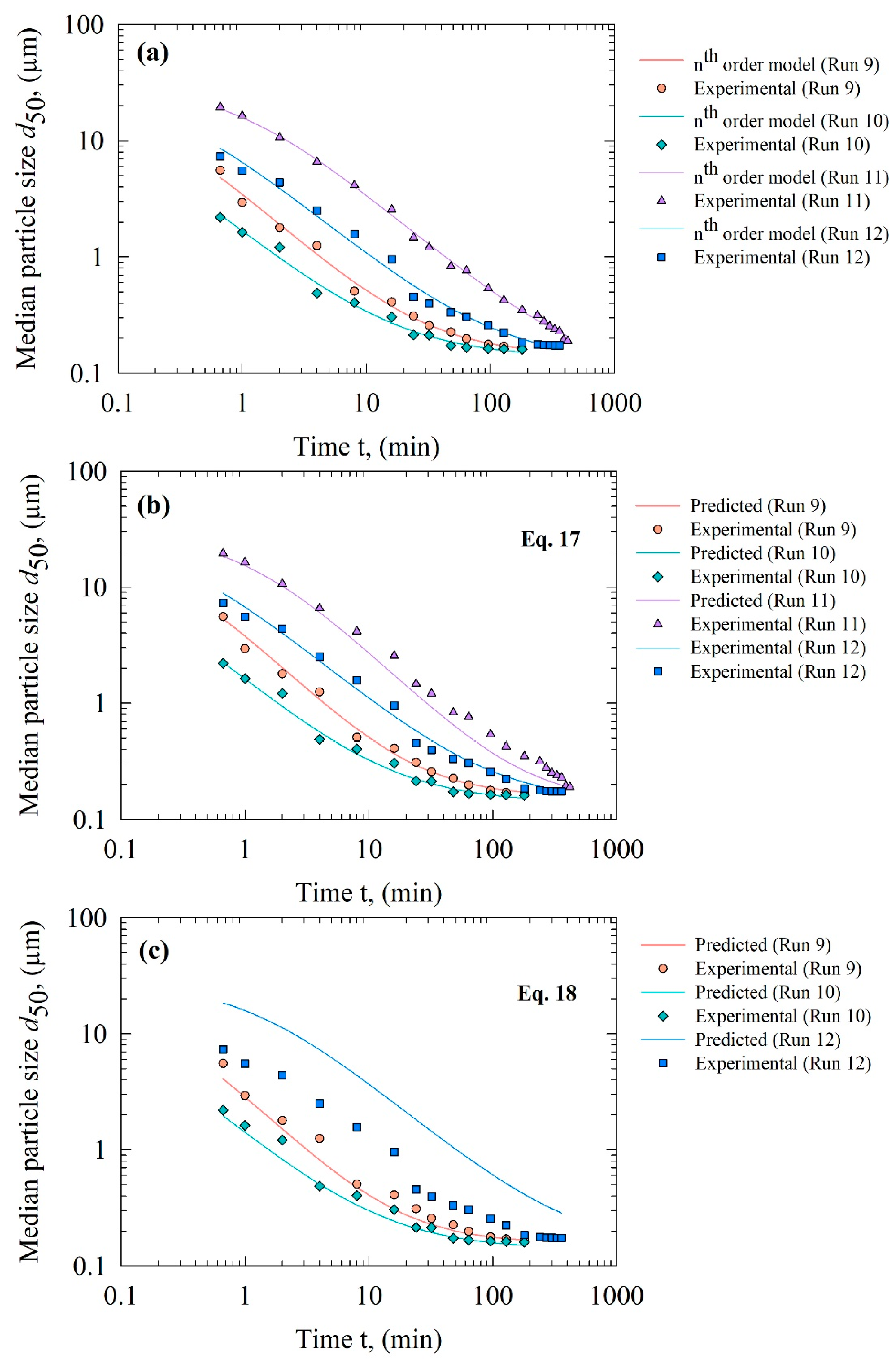
| Run | Direct Fit, Prediction | dlim (µm) | k (µmn−1min−1) | n (-) | R2 | SSR |
|---|---|---|---|---|---|---|
| 9 | nth order model fit | 0.142 | 0.264 | 2.00 | 0.996 | 0.023 |
| Prediction by Equation (17) | 0.156 | 0.280 | 1.92 | 0.995 | 0.028 | |
| Prediction by Equation (18) | 0.156 | 0.383 | 1.92 | 0.986 | 0.086 | |
| 10 | nth order model fit | 0.136 | 0.527 | 2.12 | 0.996 | 0.023 |
| Prediction by Equation (17) | 0.139 | 0.574 | 2.09 | 0.995 | 0.026 | |
| Prediction by Equation (18) | 0.139 | 0.676 | 2.09 | 0.837 | 0.257 | |
| 11 | nth order model fit | 0.093 | 0.023 | 2.09 | 0.999 | 0.015 |
| Prediction by Equation (17) | 0.156 | 0.041 | 1.92 | 0.978 | 0.156 | |
| Prediction by Equation (18) | 0.156 | −0.185 | 1.92 | N/A | N/A | |
| 12 | nth order model fit | 0.125 | 0.092 | 2.11 | 0.994 | 0.050 |
| Prediction by Equation (17) | 0.139 | 0.093 | 2.09 | 0.993 | 0.055 | |
| Prediction by Equation (18) | 0.139 | 0.021 | 2.09 | 0.644 | 2.65 |
Publisher’s Note: MDPI stays neutral with regard to jurisdictional claims in published maps and institutional affiliations. |
© 2021 by the authors. Licensee MDPI, Basel, Switzerland. This article is an open access article distributed under the terms and conditions of the Creative Commons Attribution (CC BY) license (https://creativecommons.org/licenses/by/4.0/).
Share and Cite
Guner, G.; Yilmaz, D.; Bilgili, E. Kinetic and Microhydrodynamic Modeling of Fenofibrate Nanosuspension Production in a Wet Stirred Media Mill. Pharmaceutics 2021, 13, 1055. https://doi.org/10.3390/pharmaceutics13071055
Guner G, Yilmaz D, Bilgili E. Kinetic and Microhydrodynamic Modeling of Fenofibrate Nanosuspension Production in a Wet Stirred Media Mill. Pharmaceutics. 2021; 13(7):1055. https://doi.org/10.3390/pharmaceutics13071055
Chicago/Turabian StyleGuner, Gulenay, Dogacan Yilmaz, and Ecevit Bilgili. 2021. "Kinetic and Microhydrodynamic Modeling of Fenofibrate Nanosuspension Production in a Wet Stirred Media Mill" Pharmaceutics 13, no. 7: 1055. https://doi.org/10.3390/pharmaceutics13071055