Article

Experimental Study on the Dynamic Stability of Circular Saw Blades during the Processing of Bamboo-Based Fiber Composite Panels

1
College of Computer and Control Engineering, Northeast Forestry University, Harbin 150040, China
2
National Woodworking Machinery Quality, College of Mechanical and Electrical Engineering, Northeast Forestry University, Harbin 150040, China
3
Supervision and Inspection Center, Harbin 150006, China
*
Authors to whom correspondence should be addressed.
Forests 2023, 14(9), 1855; https://doi.org/10.3390/f14091855
Submission received: 9 August 2023 / Revised: 23 August 2023 / Accepted: 7 September 2023 / Published: 12 September 2023
(This article belongs to the Special Issue New Development of Smart Forestry: Machine and Automation)

Abstract

:
Bamboo-based fiber composite panel is a new type of composite material with excellent performance. When processing bamboo-based fiber composite panels, the dynamic stability of the circular saw blade affects the surface quality of the product and the life of the machinery and equipment. Sawing heat and vibration characteristics can significantly affect the dynamic stability of circular saw blades. Circular saw blade temperature and vibration characteristics are affected by the processing parameters, and the circular saw blade temperature and vibration characteristics are analyzed by changing the processing parameters. Adopting the thermoset coupling model can be used to analyze the change rule of circular saw blade temperature when sawing bamboo-based fiber composite boards, and at the same time to analyze the change rule of circular saw blade temperature, vibration speed, and vibration acceleration through the use of by CCD experiments. The regression equations for circular saw blade temperature, vibration velocity, and vibration acceleration were derived through the use of ANOVA and significance analysis. The thermoset coupling model predictions agree with the experimental results, and the density of the isotherms is progressively thinner as the temperature is conducted from the serrated region to the body of the saw. Finally, the accuracy of the regression equations for circular saw blade temperature, vibration velocity, and vibration acceleration was checked via error analysis. The temperature change regression equation has the highest fitting accuracy, with an average error of only 1.37%; the vibration velocity and vibration acceleration regression equations have poorer fitting accuracy, with an average error of 9.5% and 11.45%, respectively, but all of them have sufficient accuracy to predict the dynamic stability of circular saw blades. The results of the study can provide some guidance for the innovative design of circular saw blades.

1. Introduction

Bamboo-based fiber composite panel (hereinafter referred to as “BFCP”) is a typical bamboo composite panel produced from bamboo. BFCP, as a new type of bamboo composite material, has been widely used in building structures, furniture manufacturing, product packaging, and so on [1,2]. The large number of species of bamboo worldwide and its short growth cycle make it a clean and renewable bio-resource, and BFCPs produced using bamboo have excellent mechanical and physical properties [3,4]. In recent years, there has been a strong interest in the use of sustainable materials around the world, and BFCP, as a sustainable material with outstanding performance, has great potential in the development of modern construction, furniture, and other industries, helping to reduce the use of resources for wood [5]. The current technology used in BFCP production and preparation is relatively mature, and most of the research focuses on how to improve the mechanical and physical properties of BFCPs [6,7,8]. However, BFCP needs to be processed into products eventually, and this process involves many mechanical processing techniques. Sawing is one of the most important processes. There are different types of BFCPs used in the sawing process, saw blade temperatures, and the sizes of the vibration are different, and the BFCP surface sawing quality is also different. Carbide-tipped circular saw blades are the main cutting tool for wood and fiberboard. In order to ensure productivity and quality, the dynamic stability and temperature variation of circular saw blades are issues that cannot be ignored [9]. As early as 2001, Tian and Hutton developed a vibration model of circular saw blades to predict the instability of transverse vibration [10], then Gendraud et al. investigated the effect of the cutting parameters on the dynamic characteristics of circular saw blades [11], and Gospodarič et al. designed an active electromagnetic system for suppressing the transverse vibration of circular saw blades, in response to the fact that circular saw blades are susceptible to lateral vibration because of time-varying loading during operation and verified it experimentally [12]. Gospodarič et al. designed an active electromagnetic system to suppress the transverse vibration of circular saw blades and verified it with tests [13]. Veselý et al. analyzed the vibration form and frequency in order to determine the form of circular saw blade vibration by directly measuring the amplitude magnitude using a displacement sensor and Fourier transform analysis [14]. Chen et al. found that circular saw blade vibration is the main cause of low wood recovery; in order to reduce the vibration of the circular saw blade during sawing, a linear quadratic Gaussian was proposed to actively control the vibration of the circular saw blade [15]. Nasir et al. investigated the effect of the rotational speed of the circular saw blade and the vibrational response on the sawing process of wood, and the rotational speed corresponding to the critical speed of the saw blade and saw blade flutter instability was identified [16], and after that, Nasir et al. used a contact thermocouple pair to measure the variation of circular saw blade temperature, and the results showed that the effect of processing parameters on circular saw blade temperature was significant, with the effect of rotational speed being the most complex [17].
In the above studies on the vibration of circular saw blades by scholars, most of the processing objects are wood and fiberboard, and there are fewer studies on the type of BFCP.BFCP and wood have similar material properties, such as both have fibers. Referring to some studies on sawing wood, it is not difficult to find that BFCP generates heat when sawing, and a large amount of heat will be transferred to the tool [18]. The circular saw blade will produce certain thermal deformation, which will affect the machining accuracy and even carbonize the material [19]; at the same time, the thermal deformation will affect the dynamic stability of the circular saw blade [20], so the heat will have a great impact on the machining performance of the circular saw blade.
In summary, under different processing parameters, the vibration characteristics and sawing heat will have an impact on the stability of circular saw blades. In this study, a thermoset coupling model is used to predict the temperature of circular saw blades when sawing BFCPs and the accuracy of the model is verified through experiments; at the same time, CCD experiments are used to explore the effects of processing parameters on the temperature, vibration speed, and vibration acceleration of circular saw blades.

2. Materials and Methods

2.1. Materials

In this study, the circular saw blade is the actuating element of the sawing machine, which consists of the saw body and teeth. The circular saw blade used in this paper is a carbide circular saw blade (Goldfield, Shanghai Goldfield Tools Co., Ltd., Shanghai, China), and the structural parameters of the circular saw blade are shown in Table 1.
The materials of the circular saw blade body and teeth are 65Mn and YG6, and the material parameters are shown in Table 2.
BFCPs are offered by the Bamboo-based Fiber Composites Manufacturing Company (Anhui Bamboo Trace New Material Technology Co., Ltd., Hefei, China). The length of the experiment samples was 400 mm, the width was 50 mm, and the thickness ranged from 28.6 to 45.4 mm. Figure 1 shows the process of test sample preparation, in which processes A-E are completed in the enterprise, and processes F g split the BFCP into sizes that meet the test requirements according to the test requirements, and the final thickness of the BFCP is between 28.6 and 45.4 mm. The spindle speed of the sawing machine (QMJ153F, Qingcheng Machinery Equipment Co., Ltd., Chengdu, China) used for the sawing test in this paper is adjustable. The material properties of BFCP are shown in Table 3.
From Table 3, it can be seen that a BFCP is an anisotropic composite material with different mechanical properties in all directions, and the sawing processing used in relation to BFCPs is a high-speed impact, large deformation, and failure process, so it is necessary to use a stress–strain model to describe the deformation and failure behavior of bamboo-based fiber composite panels. Neglecting the difference in the local density of the BFCP, the stress–strain model can be expressed in terms of the generalized Hooke’s law for representation [21].
σ 0 t i j = C 0 t i j r s ε 0 t r s
where  σ 0 t i j  is the stress,  ε 0 t r s  is the strain, and  C 0 t i j r s  is the strain function. In practice, orthotropic anisotropic materials need to be considered for three-dimensional stresses. The stress–strain model can be varied, as shown in Equation (2)
{ σ } = [ C ] { ε }
where  { σ }  is the set of stresses,  { ε }  is the set of strains, and  [ C ]  is the material’s three-way (a, b, c direction) eigenstructure matrix, and the matrix inverse can be obtained as shown in Equation (3).
[ C ] 1 = [ 1 E a v b a E b v c a E c 0 0 0 v a b E a 1 E b v c b E c 0 0 0 v a c E a v b c E b 1 E c 0 0 0 0 0 0 1 G a b 0 0 0 0 0 0 1 G b c 0 0 0 0 0 0 1 G c a ]
where  E i  is the modulus of elasticity,  v i j  is the Poisson’s ratio,  G i j  is the shear modulus, and equation  v a b E a = v b a E b v a c E a = v c a E c v b c E b = v c b E c . From this, it can be concluded that there are only three directions of Poisson’s ratio and modulus of elasticity for BFCP, which corresponds to the material properties shown in Table 3.

2.2. Thermo-Solid Coupling Model and Experimental Methods

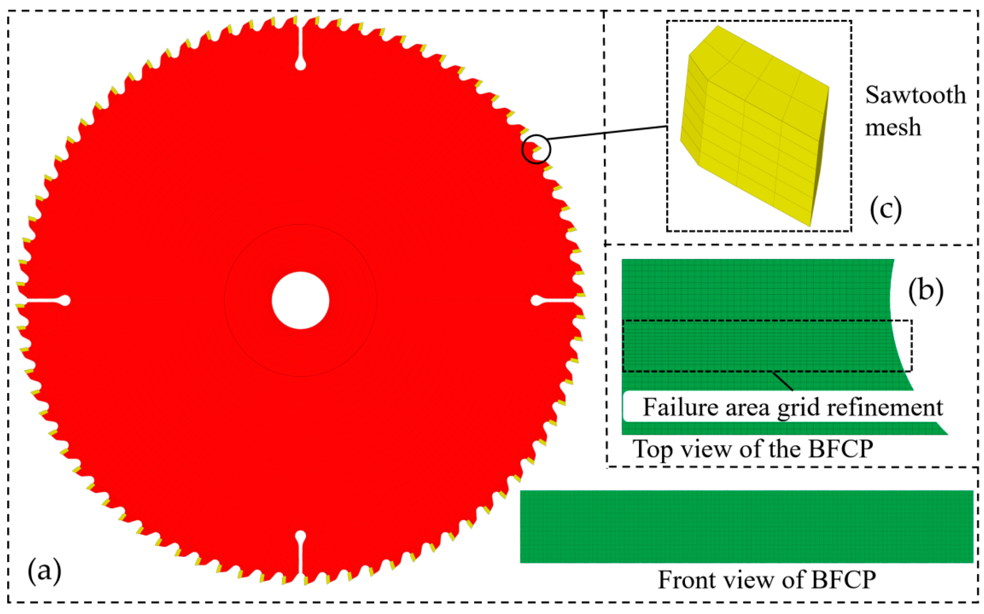
2.2.1. Thermo-Solid Coupling Model

Hypermesh 2021 and Ls-Dyna R10.1 software are used in this study to develop a thermoset-coupled model for circular saw blade dynamics. The model consists of a circular saw blade and a BFCP. Hypermesh is the FEA pre-processing software, and Ls-Dyna is the solver for FEA. The dimensional parameters of the geometry in the thermoset coupling model are consistent with the structural parameters of the circular saw blade. The numerical simulation of the thermoset coupling model is divided into pre-processing and post-processing, and the pre-processing is mainly divided into mesh delineation, adding material properties, and defining boundary conditions. In meshing, mesh quality is one of the key factors affecting the accuracy of finite element results [22]. The meshing of the model is shown in Figure 2. Figure 2a shows the model mesh, and the total mesh number of the model is 181,024, the number of nodes is 226,828, and the mesh type is hexahedron. Figure 2b shows the mesh refinement of the BFCP failure region, and Figure 2c shows the sawtooth mesh delineation.
The material properties of the model are defined in the keywords of Ls-Prepost 4.7 (Ls-Dyna pre-processing software) according to the data in Table 2 and Table 3. The material properties of sawtooth and serration are defined in the keyword “*MAT_PLASTIC_KINEMATIC”, and the material properties of the BFCP are in the keyword “*MAT_ORTHOTROPIC_ELASTIC”. First, in the kinematic boundary conditions, use the keyword “*CONTACT_ERODING_SURFACE_TO_SURFACE” to define the erosion contact between the sawtooth and the BFCP, where the BFCP is the erosion object. Secondly, define the solution time of the model, time step, spindle speed, and feed speed; when the feed speed is 7 m/s, the solution time of the model is 4.2 s, and define the solution time as 4.5 s and the time step as 0.045. Finally, define the parameters such as the dynamic and static friction coefficients; the dynamic and static coefficients of friction are 0.35 and 0.4, respectively [23].
In the thermal boundary conditions, the heat mainly comes from the mechanical energy of the interaction between the circular saw blade and the BFCP, and the mechanical energy is mainly converted into heat through three forms, i.e., there are mainly three heat source zones in the cutting process, and at the same time, the circular saw blade and the air undergo forced convection heat dissipation. Figure 3 shows the heat source zones during sawing, the main heat generating regions in sawing are given in Figure 3a, and the heat transfer process is given in Figure 3b. The three heat source zones are the first heat source zone (shear damage zone, blue line), the second heat source zone (friction zone between the tool and the machined surface, red line), and the third heat source zone (friction zone between the chip and the tool, magenta line). The green arrow in Figure 3a indicates forced convection heat dissipation. The BFCP undergoes elastic–plastic deformation during sawing and generates heat when it fails, a process that occurs in the first heat source region. Frictional heat is generated by the friction between the saw teeth and the new surface, and this process occurs in the second heat source region. The friction between the circular saw blade and the chips generates heat, while 60% of the heat is converted into thermal energy, and this process occurs in the third heat source zone [20]. The above heat source zones are generated when the BFCP deforms and fails and cannot be represented by keywords in the pre-treatment.
Forced convective heat dissipation occurs in laminar and turbulent regions. Laminar and turbulent heat dissipation occur in the region of low and high linear velocities on the surface of the circular saw blade, respectively [24], so it is necessary to add air-forced convection heat dissipation to the boundary conditions of the model, while the external ambient temperature is set to 26.4  ° C  (room temperature). Laminar and turbulent regions of circular saw blades need to be judged through the use of Reynolds number representation [25], while the Reynolds number and convective thermal conductivity coefficient are unknown quantities, and the laminar and turbulent regions are solved and judged through the use of the Reynolds number equation. The Reynolds number equation for the high-speed rotational heat transfer process is shown in Equation (4), and the thermal parameters of air are shown in Table 4.
R e = V f D v 1
where  R e  is Reynolds,  V f  is the spindle speed in m/s, D is the circular saw blade diameter in m, and  v 1  is the kinematic viscosity of air.
A spindle speed of 3000 r/min (linear velocity of 39.9 m/s) is used as an example to solve for the region of laminar and turbulent flow of a circular saw blade. According to Equation (4), the Reynolds number of the edge region of the circular saw blade is  6.767 × 10 5 , when the Reynolds number is less than 2000 for laminar flow and greater than 4000 for turbulent flow [26], it can be concluded that the saw tooth region (Figure 4) belongs to turbulent region, at the same time, through the calculation of the circular saw blade, can be known to be in the turbulent region. The convective heat transfer coefficient in the turbulent zone can be derived from the Nussell number ( N μ ) and the empirical equations obtained from scholarly studies [27,28]. The Nussell number formula is shown in (5), and the empirical equations are shown in (6) and (7).
N μ = h L k
N μ = ( 0.277 + 0.105 P r ) × R e
N μ = 0.015 R e 0.8
where h is the convective thermal conductivity and L is the characteristic length, and the value is the diameter of the circular saw blade. k is the thermal conductivity of air.
The joint formulations (5)–(7) give the convective thermal conductivity of the sawtooth region at a spindle speed of 3000 r/min as 14.68  W / ( m · k ) . This coefficient is defined using the thermo-solid coupling model.

2.2.2. Temperature Measurement

The temperature of the sawtooth region during sawing of the BFCP was measured using a high-precision infrared thermometer (Fluke F562, Fluke company, Everett, WA, USA) with a response time of less than 0.5 s and a resolution of 0.1  ° C . The method of temperature measurement in the sawtooth region is shown in Figure 4; a schematic diagram of the sawtooth temperature measurement is shown in Figure 4a, and a measurement device is shown in Figure 4b.

2.2.3. Vibration Measurements

Circular saw blades rotate at high speeds during operation, so a non-contact measurement method was chosen. In the paper, a vibration analyzer (AHAI3002, Hangzhou Aihua Instrument Co., Ltd., Hangzhou, China) was used to measure the vibration parameters during sawing of BFCP. The analyzer measures the velocity, acceleration, and displacement of vibration, and the sampling frequencies for the three parameters are 32 Hz–13 kHz, 32 Hz–5.0 kHz, and 32 Hz–2 Hz, respectively. Considering the low sampling frequency of vibration displacement, only vibration velocity and vibration acceleration are studied in the paper. The sampling frequencies in the test were set to 13 kHz and 5 kHz for collecting the maximum effective values of vibration velocity and vibration acceleration, respectively. Figure 5a shows a schematic diagram of the vibration measurement system, the length of the sensor axis to the axis of the circular saw blade is 120 mm, and the distance from the guard plate to the circular saw blade is 40 mm. Figure 5b shows the vibration measurement device, where the sensor is fixed on the guard plate to collect the data and processed using the vibration analyzer, and finally connected to the computer via USB to be visualized using the host computer software (Aihua intelligent upper computer management system V1.6.6.5).

2.2.4. CCD Experiment

CCD experiment is a test based on Response Surface Methodology (RSM). RSM is a mathematical analysis that combines mathematics and statistics and can be used to analyze the correlation of various factors and indicators [29]. The main processing parameters for BFCP sawing are spindle speed, feed rate, and thickness of the BFCP being processed. In different combinations of these parameters, the dynamic stability of circular saw blades varies. Temperature and vibration characteristics affect the dynamic stability of circular saw blades [9,30].
In this paper, the spindle speed n, feed speed Vf, and BFCP thickness Cd are taken as the influencing factors in the study, and temperature, vibration speed, and vibration acceleration are taken as the indexes to design a three-factor, five-level experiment. The levels and indicators for the experiment are shown in Table 5.

3. Results and Discussion

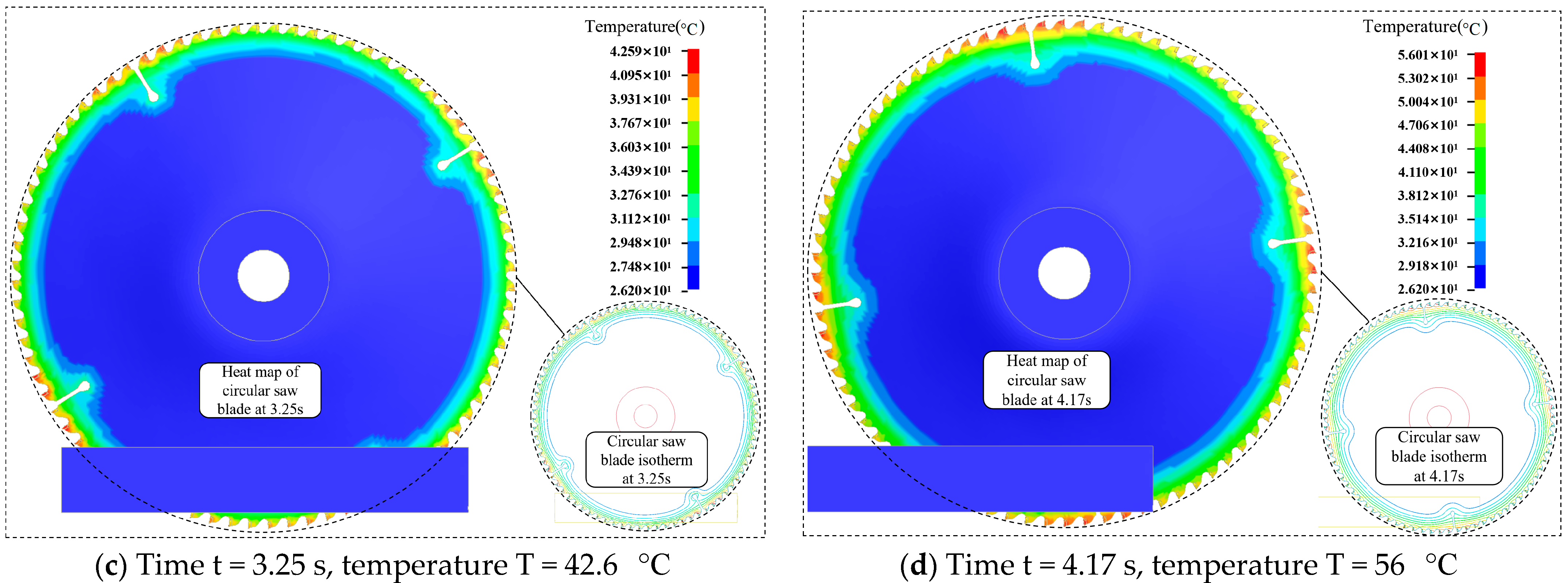
3.1. Analysis of Thermo-Solid Coupling Model Results

The temperature variation of a circular saw blade is shown in Figure 6 when the spindle speed is 3000 r/min, the feed speed is 7 m/min and the thickness of the BFCP is 32 mm. Figure 6a shows the initial temperature of the circular saw blade; Figure 6b shows the temperature distribution of the circular saw blade with isotherms at time t = 1.525 s; Figure 6c shows the temperature distribution of the circular saw blade with isotherms at time t = 3.25 s; and Figure 6d shows the temperature distribution of the circular saw blade with isotherms at time t = 4.17 s. The maximum temperature in the sawtooth region in Figure 6 is 56  ° C . From Figure 6b–d, concerning the temperature change of the circular saw blade, it can be concluded that the temperature of the saw teeth after the collision between the circular saw blade and the BFCP rises rapidly, and at the same time, it is transmitted to the muffling groove and other regions of the circular saw blade, which is consistent with the rule of change investigated in the literature [20], and it also demonstrates the accuracy and reliability of the thermo-solid coupling model in this paper. In the isotherm plots of Figure 6c,d, the temperature on the circular saw blade is conducted from the teeth of the saw to the axis of the saw body, and the isotherm lines become sparse from dense, which indicates that the temperature difference gradually decreases, and the results of the study are the same as those present in the literature [31].

3.2. Analysis of Experiment Results

3.2.1. Temperature Correlation Analysis

The BFCP sawing experiment was conducted in a room with a temperature of 26.4  ° C , an air humidity of 61%, and an initial temperature in the sawing area of 26.2  ° C . The values of the experimental results are shown in Table 6, with a total of 20 sets of experiments, of which five were replicated.
The process parameters in the thermoset coupling model are consistent with the Group 4 experiment; the maximum value of the experiment temperature is 49.4  ° C , the maximum value of the thermoset coupling model temperature is 56.0  ° C , and the error of the thermoset coupling model is 13.4%, which is small enough to indicate that the numerical solution of the model is reliable. The precision of the regression equation can be determined via ANOVA and significance test [32]. The ANOVA and significance tests for temperature changes are given in Table 7, and the regression model was overall significant (p < 0.0001). The single terms spindle speed n, feed speed  V f , and BFCP thickness  C d  are all highly significant terms and the most significant of spindle speed. Equation (8) is the regression equation for temperature change.
T e = 4.55 + 0.0004 n 5.8 V f + 0.085 C d 0.0004 n C d 0.12 V f C d + ( 4.8 E - 6 ) n 2 + 0.03 C d 2
Figure 7 gives the law of the effect of interaction terms on temperature, Figure 7a shows the effect of spindle speed and BFCP thickness on temperature, and Figure 7c shows the effect of feed speed and BFCP thickness on temperature. With the increase in spindle speed and BFCP thickness parameter value, as shown in Figure 7a, the temperature of the circular saw blade presents a nonlinear increase, and the change rule of the circular saw blade temperature in Figure 7d is similar to that of Figure 7a, but the trend of the temperature rise in Figure 7a is greater than that of Figure 7d, and the change rule of the temperature is similar to that present in the literature [17,30]. In Figure 7b, the density of isotherms when the thickness of BFCP is increased from 32 mm to 40 mm is greater than the density of isotherms when the spindle speed is increased from 2000 r/min to 3000 r/min, which indicates that the temperature is more susceptible to the influence of spindle speed [17]. Similarly, the density of isotherms in Figure 7d indicates that temperature is affected by BFCP thickness to a greater extent than by feed speed.

3.2.2. Vibration Velocity Correlation Analysis

Table 8 gives the ANOVA and significance analysis for vibration speed. The overall significance of the regression model is significant (p < 0.0001); the model spindle speed n, feed speed  V f , and BFCP thickness  C d  are significant terms, and none of the interaction terms of the model are significant. Equation (9) gives the vibration speed regression equation.
V s = 47.32 0.057 n + 1.68 V f + 0.48 C d + ( 1.3 × 10 5 ) n 2
The interaction terms in Table 8 were not significant and required a one-way analysis of variance for the individual terms. The single-factor analysis of vibration speed is given in Figure 8, Figure 8a shows the effect of spindle speed on vibration speed; Figure 8b shows the effect of feed rate on vibration speed; and Figure 8c shows the effect of BFCP thickness on vibration speed. The vibration velocity in Figure 8a has extreme values at both low and high rotational speeds. When the rotational speed is low, there will be sawing difficulties; the sawing force increases sharply, resulting in poor stability of the circular saw blade. When the rotational speed is too large, the circular saw blade’s transverse vibration speed increases, thus reducing the stability of the circular saw blade [33]. The vibration speed increases with the increase in feed rate and BFCP thickness in Figure 8b,c because the unit cutting volume of the circular saw blade increases when the feed rate and the thickness of the BFCP are larger, resulting in the deterioration of the stability of the circular saw blade, which is in agreement with the results present in the literature [33].

3.2.3. Vibration Acceleration Correlation Analysis

Table 9 gives the analysis of the variance and significance of vibration velocity. The regression model is significant overall (p < 0.0001), the single term of the model is significant, and the interaction term is not significant. Equation (10) gives the regression equation for the variation of vibration velocity.
V a = 42.84 + 0.0075 n + 1.76 V f + 0.69 C d
Figure 9 gives the one-factor analysis of vibration acceleration. Figure 9a–c shows the effect of spindle speed, feed rate, and BFCP thickness on vibration acceleration, respectively. The spindle speed has the greatest degree of influence on the vibration acceleration in Figure 9, followed by the BFCP thickness and, finally, the feed speed. The vibration acceleration reflects the magnitude of the impact force (cutting force), indicating that the magnitude of the impact force is nonlinearly and positively correlated with the spindle rotational speed, feed rate, and BFCP thickness [34].

3.3. Temperature Regression Equation Error Test

The regression equation for temperature was fitted in Section 3.2 above. Figure 10 gives the 20 sets of predicted values of the regression equation compared to the experimental values and the error curve. The maximum error in the predicted values of the equations in Figure 10 is 3.7%, and the average error is 1.65%. The small error indicates that the regression equations are highly reliable, and the temperature regression equations can be utilized to predict the temperature changes in the sawtooth region when machining the BFCP.

3.4. Circular Saw Blade Vibration Regression Equation Error Test

The predicted versus true values of the vibration parameters of the regression equation and the error curve are shown in Figure 11. Compared with the temperature regression equation, the fitting accuracy of vibration velocity and vibration acceleration is poorer, with maximum errors of 34.6% and 59.6% and average errors of 9.5% and 11.45% for the experimental group, respectively. It is not difficult to find out from the installation method and location of the sensor that the vibration transmission to the guard plate is a very complicated process, and it is also affected by the tension force [9], thermal stress [35], and cutting force [36], so that the measured data in some groups have a large error. More advanced devices or methods can be used to measure the vibration parameters in subsequent studies. Except for some groups, the average errors of vibration velocity and vibration acceleration are relatively small, and the regression equation can be used to make a simple prediction of the vibration parameters.

3.5. Sawing Quality Analysis

The surface quality of the BFCP after sawing in some groups is demonstrated in Figure 12. It can be seen in the figure that the surface quality of the BFCP in groups 1, 8, and 11 tests is better, with shallow sawtooth marks and smooth surfaces. Groups 9, 12, 15, 16, and 17 had deep sawtooth marks and large widths with poor surface quality. The test groups that had BFCPs with poorer surface quality had larger values in terms of temperature, vibration acceleration, and velocity. However, the surface quality of the 9th group of tests was the worst, while the temperature, vibration acceleration, and velocity values of the 9th group of tests were smaller than those of the 12th group, indicating that the surface quality was also affected by other factors (hardness, moisture content, etc.) [37]. The influencing factors can be considered more comprehensively in subsequent studies to compare and analyze the effects of factors on BFCP surface quality.

4. Conclusions

In this study, the dynamic stability of circular saw blades in BFCP processing is investigated using the thermoset coupling model and a CCD experiment. In the thermoset coupling model, the temperature is gently conducted from the saw tooth region to the saw body, with clear isothermal boundaries, and the higher temperature regions are mainly the sawtooth, chip removal groove, and muffler groove. For the prediction of circular saw blade temperature value pairs, the prediction accuracy of the regression equation fitted via variance and significance analysis is more accurate than that predicted via a numerical simulation of the heat-solid coupling model. The fitting accuracy of the regression equations for vibration velocity and vibration acceleration is poorer, and the error values of individual test groups are large, but the average error is relatively small. The experimental methods and equipment can be improved in future research to improve the accuracy of the data. The development of the heat-solid coupling model and regression equation in this paper can provide some theoretical support for the innovative design of circular saw blades.

Author Contributions

Conceptualization, Y.M.; methodology, Y.D.; software, Y.M.; validation, T.L. and Y.M.; formal analysis, Y.D.; investigation, Y.D.; resources, J.Z.; data curation, C.Y.; writing, original draft preparation, Y.D.; writing—review and editing, Y.M.; visualization, Y.M.; supervision, C.Y.; project administration, Y.D.; funding acquisition, J.Z. All authors have read and agreed to the published version of the manuscript.

Funding

This research was funded by “Major Special R&D Programs in Guangdong Province (2020B020216001)” and “Key Programs of Heilongjiang Provincial Nature Fund (ZD2021E001)”.

Data Availability Statement

Not applicable.

Acknowledgments

We would like to thank Ma Yan for his patience guidancein the thermoset coupling analysis.

Conflicts of Interest

The authors declare no conflict of interest.

References

  1. Li, X.; Li, L.; Li, N.; Bao, M.; Bao, Y.; Wu, Z.; Wang, J.; Rao, F.; Chen, Y. Sustainable production of engineered bamboo scrimber composites for construction and flooring applications. Constr. Build. Mater. 2022, 347, 128615. [Google Scholar] [CrossRef]
  2. Kumar, R.; Ganguly, A.; Purohit, R. Properties and applications of bamboo and bamboo fibre composites. Mater. Today Proc. 2023. [Google Scholar] [CrossRef]
  3. Wang, Y.-Y.; Guo, F.-L.; Li, Y.-Q.; Zhu, W.-B.; Li, Y.; Huang, P.; Hu, N.; Fu, S.-Y. High overall performance transparent bamboo composite via a lignin-modification strategy. Compos. Part B Eng. 2022, 235, 109798. [Google Scholar] [CrossRef]
  4. Hasan, K.F.; Al Hasan, K.N.; Ahmed, T.; György, S.-T.; Pervez, N.; Bejó, L.; Sándor, B.; Alpár, T. Sustainable bamboo fiber reinforced polymeric composites for structural applications: A mini review of recent advances and future prospects. Case Stud. Chem. Environ. Eng. 2023, 8, 100362. [Google Scholar] [CrossRef]
  5. Kelkar, B.; Shukla, S.; Nagraik, P.; Paul, B. Structural bamboo composites: A review of processing, factors affecting properties and recent advances. Adv. Bamboo Sci. 2023, 3, 100026. [Google Scholar] [CrossRef]
  6. Gao, X.; Zhu, D.; Fan, S.; Rahman, Z.; Guo, S.; Chen, F. Structural and mechanical properties of bamboo fiber bundle and fiber/bundle reinforced composites: A review. J. Mater. Res. Technol. 2022, 19, 1162–1190. [Google Scholar] [CrossRef]
  7. Li, X.; Lei, W.; Zhang, Z.; Zhang, W.; Li, N.; Yu, Y.; Li, C.; Chen, Y.; Rao, F. Fabrication and mechanical behavior of scalable lightweight high-strength cork–bamboo sandwich composites. Ind. Crop. Prod. 2023, 192, 116068. [Google Scholar] [CrossRef]
  8. Xie, X.; Zhou, Z.; Yan, Y. Flexural properties and impact behaviour analysis of bamboo cellulosic fibers filled cement based composites. Constr. Build. Mater. 2019, 220, 403–414. [Google Scholar] [CrossRef]
  9. Li, S.; Wang, C.; Zheng, L.; Wang, Y.; Xu, X.; Ding, F. Dynamic stability of cemented carbide circular saw blades for woodcutting. J. Mater. Process. Technol. 2016, 238, 108–123. [Google Scholar] [CrossRef]
  10. Tian, J.F.; Hutton, S.G. Cutting-induced vibration in circular saws. J. Sound Vib. 2001, 242, 907–922. [Google Scholar] [CrossRef]
  11. Gendraud, P.; Roux, J.C.; Bergheau, J.M. Vibrations and stresses in band saws—A review of literature for application to the case of aluminium-cutting high-speed band saws. J. Mater. Process. Technol. 2003, 135, 109–116. [Google Scholar] [CrossRef]
  12. Gospodarič, B.; Bučar, B.; Fajdiga, G. Active vibration control of circular saw blades. Eur. J. Wood Wood Prod. 2015, 73, 151–158. [Google Scholar] [CrossRef]
  13. Anđelić, N.; Braut, S.; Pavlović, A. Variation of natural frequencies by circular saw blade rotation. Teh. Vjesn. 2018, 25, 10–17. [Google Scholar]
  14. Veselý, P.; Kopecký, Z.; Hejmal, Z.; Pokorný, P. Diagnostics of Circular Sawblade Vibration by Displacement Sensors. Drv. Ind. 2012, 63, 81–86. [Google Scholar] [CrossRef]
  15. Chen, Y.; Wang, X.G.; Sun, C.; Devine, F.; De Silva, C.W. Active vibration control with state feedback in woodcutting. J. Vib. Control 2003, 9, 645–664. [Google Scholar] [CrossRef]
  16. Nasir, V.; Mohammadpanah, A.; Cool, J. The effect of rotation speed on the power consumption and cutting accuracy of guided circular saw: Experimental measurement and analysis of saw critical and flutter speeds. Wood Mater. Sci. Eng. 2020, 15, 140–146. [Google Scholar] [CrossRef]
  17. Nasir, V.; Kooshkbaghi, M.; Cool, J.; Sassani, F. Cutting tool temperature monitoring in circular sawing: Measurement and multi-sensor feature fusion-based prediction. Int. J. Adv. Manuf. Technol. 2021, 112, 2413–2424. [Google Scholar] [CrossRef]
  18. Svoreň, J.; Naščák, L.; Barcík, S.; Koleda, P.; Stehlík, S. Influence of Circular Saw Blade Design on Reducing Energy Consumption of a Circular Saw in the Cutting Process. Appl. Sci. 2022, 12, 1276. [Google Scholar] [CrossRef]
  19. Pavlovic, A.; Fragassa, C. Numerical modelling of ballistic impacts on flexible protection curtains used as safety protection in woodworking. Proc. Inst. Mech. Eng. Part C J. Mech. Eng. Sci. 2017, 231, 44–58. [Google Scholar] [CrossRef]
  20. Yu, M.; Wang, B.; Ji, P.; Li, B.; Zhang, L.; Zhang, Q. Study on the dynamic stability of circular saw blade during medium density fiberboard sawing process with thermo-mechanical coupling. Comput. Electron. Agric. 2023, 211, 108042. [Google Scholar] [CrossRef]
  21. Roth, C.C.; Mohr, D. Effect of strain rate on ductile fracture initiation in advanced high strength steel sheets: Experiments and modeling. Int. J. Plast. 2014, 56, 19–44. [Google Scholar] [CrossRef]
  22. Peng, W.; Wang, L.; Lu, D. Local to Global Optimization Algorithm for Hexahedral Mesh Quality. J. Mech. Eng. 2014, 50, 140–146. [Google Scholar] [CrossRef]
  23. Bejo, L.; Lang, E.M.; Fodor, T. Friction coefficients of wood-based structural composites. For. Prod. J. 2000, 50, 39–43. [Google Scholar]
  24. Tirovic, M.; Topouris, S.; Sherwood, G. Experimental investigation of the cooling characteristics of a monobloc cast iron brake disc with fingered hub. Proc. Inst. Mech. Eng. Part D J. Automob. Eng. 2020, 234, 85–97. [Google Scholar] [CrossRef]
  25. Abraham, J.P.; Sparrow, E.M.; Minkowycz, W.J. Internal-flow Nusselt numbers for the low-Reynolds-number end of the laminar-to-turbulent transition regime. Int. J. Heat Mass Transf. 2011, 54, 584–588. [Google Scholar] [CrossRef]
  26. Jin, D.J.; Uhm, H.S.; Cho, G. Influence of the gas-flow Reynolds number on a plasma column in a glass tube. Phys. Plasmas 2013, 20, 083513. [Google Scholar] [CrossRef]
  27. Cobb, E.C.; Saunders, O.A. Heat transfer from a rotating disk. Proceedings of the Royal Society of London. Ser. A Math. Phys. Sci. 1956, 236, 343–351. [Google Scholar]
  28. Northrop, A.; Owen, J.M. Heat transfer measurements in rotating-disc systems part 1: The free disc. Int. J. Heat Fluid Flow 1988, 9, 19–26. [Google Scholar] [CrossRef]
  29. Mishra, H.P.; Jalan, A. Analysis of faults in rotor-bearing system using three-level full factorial design and response surface methodology. Noise Vib. Worldw. 2021, 52, 365–376. [Google Scholar] [CrossRef]
  30. Wang, Y.; Wang, Z.; Ni, P.; Wang, D.; Lu, Y.; Lu, H.; Guo, S.; Chen, Z. Experimental and Numerical Study on Regulation of Cutting Temperature during the Circular Sawing of 45 Steel. Coatings 2023, 13, 758. [Google Scholar] [CrossRef]
  31. Svoreň, J.; Javorek, Ľ.; Krajčovičová, M.; Klobušiaková, K. The effect of the circular saw blade body structure on the concentric distribution of the temperature along the radius during the wood cutting process. Wood Res. 2017, 62, 427–436. [Google Scholar]
  32. Izzet, A. Application of Taguchi method for cutting force optimization in rock sawing by circular diamond sawblades. Sadhana 2014, 39, 1055–1070. [Google Scholar]
  33. Meng, Y.; Wei, J.; Wei, J.; Chen, H.; Cui, Y. An ANSYS/LS-DYNA simulation and experimental study of circular saw blade cutting system of mulberry cutting machine. Comput. Electron. Agric. 2018, 157, 38–48. [Google Scholar] [CrossRef]
  34. Ghani, J.A.; Choudhury, I.A.; Masjuki, H.H. Performance of P10 TiN coated carbide tools when end milling AISI H13 tool steel at high cutting speed. J. Mater. Process. Technol. 2004, 153, 1062–1066. [Google Scholar] [CrossRef]
  35. Heisel, U.; Stehle, T.; Ghassemi, H. A simulation model for analysis of roll tensioning of circular saw blade. Adv. Mater. Res. 2014, 1018, 57–66. [Google Scholar] [CrossRef]
  36. Wang, P.; Ge, P.; Gao, Y.; Bi, W. Prediction of sawing force for single-crystal silicon carbide with fixed abrasive diamond wire saw. Mater. Sci. Semicond. Process. 2017, 63, 25–32. [Google Scholar] [CrossRef]
  37. Laina, R.; Sanz-Lobera, A.; Villasante, A.; López-Espí, P.; Martínez-Rojas, J.A.; Alpuente, J.; Sánchez-Montero, R.; Vignote, S. Effect of the anatomical structure, wood properties and machining conditions on surface roughness of wood. Maderas Cienc. tecnol. 2017, 19, 203–212. [Google Scholar] [CrossRef]
Figure 1. Process flow of experiment sample preparation.
Forests 14 01855 g001
Figure 2. Model meshing diagram; (a) model mesh; (b) mesh refinement of BFCP failure region; (c) sawtooth mesh.
Forests 14 01855 g002
Figure 3. Circular saw blade heat transfer analysis. (a) main heat-generating areas during sawing; (b) heat transfer process.
Forests 14 01855 g003
Figure 4. Method of measuring temperature in the sawtooth region; (a) temperature measurement region; (b) temperature measurement device.
Forests 14 01855 g004
Figure 5. Vibration measurement system; (a) schematic diagram of the vibration measurement system; (b) vibration measurement device.
Forests 14 01855 g005
Figure 6. Plot of circular saw blade temperature vs. isotherm variation.
Forests 14 01855 g006aForests 14 01855 g006b
Figure 7. Effect of the interaction term on temperature. (a C d /n interaction term on temperature  T e ; (b) contour plot of (a); (c C d / V f  interaction term on temperature; (d) contour plot of (c).
Forests 14 01855 g007
Figure 8. Single factor analysis of vibration speed. (a) Effect of spindle speed on vibration speed; (b) effect of feed rate on vibration speed; (c) effect of BFCP thickness on vibration speed.
Forests 14 01855 g008
Figure 9. One-factor analysis of vibration acceleration. (a) Effect of spindle speed on vibration acceleration; (b) effect of feed rate on vibration acceleration; (c) effect of BFCP thickness on vibration acceleration.
Forests 14 01855 g009
Figure 10. Error analysis of actual and predicted values of temperature.
Forests 14 01855 g010
Figure 11. Error analysis of actual versus predicted values of vibration parameters. (a) Error analysis of actual and predicted values of vibration velocity; (b) error analysis of actual and predicted values of vibration acceleration.
Forests 14 01855 g011
Figure 12. Sawing quality analysis.
Forests 14 01855 g012
Table 1. Parameters of circular saw blade.
Diameter (mm)Aperture (mm)Tooth Number (T)Tooth Width (mm)Tooth Thickness (mm)Saw Blade Thickness (mm)Anterior Angle (°)Rear Angle (°)
25425.4802.8321515
Table 2. Material properties of saw body and teeth.
Materials65Mn (Saw Body)YG6 (Serrated)
Density (kg/m3)782014,200
Poisson’s ratio0.2820.3
Modulus of elasticity (GPa)206511
Yielding strength (GPa)0.7850.43
Specific heat ( J / kg · ° C )480220
Thermal conductivity (W/mK)4875
Coefficient of thermal expansion (%)1.2 × 10−56.0 × 10−6
Table 3. BFCP material properties.
PropertyBFCP
Density (kg/m3)1350
Porosity (%)5.52
Water absorption (%)9.67
Radial Poisson’s ratio0.127
Longitudinal Poisson’s ratio0.29
Tangential Poisson’s ratio0.24
Radial modulus of elasticity (GPa)3.07
Longitudinal modulus of elasticity (GPa)15.2
Tangential modulus of elasticity (GPa)1.204
Thermal conductivity (W/mK)0.35
Specific   heat   ( J / ( kg · ° C ) )1750
Coefficient of thermal expansion (%)1.2 × 10⁻⁵
Tensile strength (MPa)28.83
Compressive strength (MPa)215.32
Bending strength (MPa)28.36
Table 4. Thermal parameters of air.
Thermal   Conductivity   k   ( W / ( m · k ) )Kinematic Viscosity
v 1  (m2/s)
Plante Number
Pr
0.02511.5 × 10−50.72
Table 5. CCD experiment levels and factors.
LevelFactors
Spindle Speed n (r/min)Feeding Speed
Vf (m/min)
Wood Thickness
Cd (mm)
+1.681659.16.028.6
+12000.07.032.0
02500.08.537.0
−13000.010.042.0
−1.683340.911.045.4
Table 6. CCD experiment results.
GroupsSpindle Speed
n (r/min)
Feed Speed
V f  (m/min)
BFCP Thickness  C d  (mm)Temp
T e   ( ° C )
Vibration Speed  V s  (mm/s)Vibration Acceleration  V a   ( mm / s 2 )
125006.037.043.78.6713.52
225008.537.048.216.8610.42
3300010.042.057.429.2927.83
430007.032.049.418.6213.76
5200010.032.043.412.1912.92
625008.545.454.218.4022.84
725008.537.049.814.7816.24
825008.528.647.911.2414.12
9250011.037.050.821.9421.83
10200010.042.048.819.3119.61
1120007.032.038.513.346.23
1233408.537.059.328.0425.64
1325008.537.049.116.1119.74
14300010.032.055.221.2715.18
1530007.042.054.422.1918.89
1625008.537.048.417.4116.45
1716608.537.044.821.888.48
1825008.537.047.215.8516.75
1920007.042.048.515.6914.39
2025008.537.047.618.4517.78
Standard deviation of vibration parameters4.845.025.27
Table 7. Analysis of temperature variance and significance test. Model R2 = 0.96; Adjusted R2 = 0.94; Predicted R2 = 0.86; Adeq Precision = 26.27. The overall regression of the model is significant (p < 0.0001), and F-value = 45.81 indicates that the probability of the model being affected by noise is 0.01%. (p < 0.05 means highly significant, 0.1 < p < 0.05 means significant; p > 0.1 means not significant).
SourceSum of SquaresdfMean SquareF-Valuep-Value
Model451.31764.4745.81<0.0001Significant
n-Spindle speed277.721277.72197.33<0.0001
V f -Feed speed49.27149.2735.01<0.0001
C d -Thicknesses80.69180.6957.33<0.0001
n   C d 8.4118.415.970.0309
V f   C d 6.8516.854.860.0477
n220.59120.5914.630.0024
C d 2 10.17110.177.230.0197
Residual16.89121.41
Lack of Fit12.3271.761.930.2441Not significant
Pure Error4.5750.9137
Cor Total468.219
Table 8. ANOVA for vibration velocity and significance test. Model R2 = 0.869; Adjusted R2 = 0.834; Predicted R2 = 0.708; Adeq Precision = 17.97. The overall regression of the model was significant (p < 0.0001), and the F-value = 24.96 indicated that the model was affected by noise with a probability of 0.01%. (p < 0.05 indicates highly significant, 0.1 < p < 0.05 indicates significant; p > 0.1 indicates not significant).
SourceSum of SquaresdfMean SquareF-Valuep-Value
Model437.494109.3724.96<0.0001Significant
n-Spindle speed124.291124.2928.37<0.0001
V f -Feed speed87.34187.3419.940.0005
C d -Thicknesses80.23180.2318.310.0007
C d 2 145.621145.6233.24<0.0001
Residual65.72154.38
Lack of Fit57.46105.753.480.0906Not significant
Pure Error8.2651.65
Cor Total503.219
Table 9. Analysis of variance and significance of vibration velocity. Model R2 = 0.815; Adjusted R2 = 0.781; Predicted R2 = 0.725; Adeq Precision = 17.46. The overall regression of the model is significant (p < 0.0001), and the F-value = 23.6 indicates that the probability that the model is affected by noise is 0.01%. (p < 0.05 means highly significant, 0.1 < p < 0.05 means significant; p > 0.1 means not significant).
SourceSum of SquaresdfMean SquareF-Valuep-Value
Model453.213151.0723.6<0.0001Significant
n-Spindle speed193.221193.2230.18<0.0001
V f -Feed speed96.2196.215.030.0013
C d -Thicknesses163.791163.7925.580.0001
Residual102.44166.4
Lack of Fit53.64114.880.49960.8432Not significant
Pure Error48.859.76
Cor Total555.6519
Disclaimer/Publisher’s Note: The statements, opinions and data contained in all publications are solely those of the individual author(s) and contributor(s) and not of MDPI and/or the editor(s). MDPI and/or the editor(s) disclaim responsibility for any injury to people or property resulting from any ideas, methods, instructions or products referred to in the content.

