Article

European Yield Model Exponential Decay Constant Modification for Glulam after Fire Exposure

1
Faculty of Engineering, Science & Technology, Infrastructure University Kuala Lumpur (IUKL), Unipark Suria, Jalan Ikram-Uniten, Kajang 43000, Malaysia
2
Institute for Infrastructure Engineering and Sustainable Management (IIESM), University Teknologi MARA, Shah Alam 40450, Malaysia
3
Laman Seri Builder Group Sdn. Bhd., Shah Alam 40000, Malaysia
4
Arkitek Azman Zainal Sdn. Bhd., Shah Alam 40100, Malaysia
5
Civil and Environmental Engineering Department, Gadjah Mada University, Grafika Street # 2, Sleman, Yogyakarta 55281, Indonesia
6
Laboratory of Biocomposite Technology, Institute of Tropical Forestry and Forest Products (INTROP), Universiti Putra Malaysia (UPM), Serdang 43400, Malaysia
*
Author to whom correspondence should be addressed.
Forests 2022, 13(12), 2012; https://doi.org/10.3390/f13122012
Submission received: 26 September 2022 / Revised: 9 November 2022 / Accepted: 24 November 2022 / Published: 28 November 2022
(This article belongs to the Special Issue Frontiers in Modification of Wood and Wood-Based Composites)

Abstract

:
Many real-scale fire tests have been performed on timber connections to analyze the mechanical behavior of timber connections in previous years. However, little research focused on the bending performance of glued laminated (glulam) timber beam bolted connections after fire exposure. In this paper, the three-dimensional numerical model of the glulam timber beam bolted connections was developed and validated by experimental results. The model can simulate temperature evolution in the connections and their mechanical behavior. In the real-scale test, three (3) samples were prepared for a four-point bending test at normal temperature, while another three (3) samples were tested after exposure to a 30-min standard fire and cooled down to normal temperature. The results show the reduction of the load-carrying capacity before and after exposure to the standard fire by 23.9 kN (71.8%), 8.3 kN (26.1%), and 20.2 kN (47.6%) for bolt diameters of 12 mm, 16 mm, and 20 mm, respectively. The numerical model aims to conduct a parametric study and propose the modification of the exponential decay constant, k, for tropical glulam timber to predict the load-carrying capacity of the glulam timber beam bolted connections after exposure to standard fire.

1. Introduction

A few different modeling approaches can be used to simulate the behavior of timber connections at a normal temperature. These include an empirical model, an analytical model based on a mechanics approach, and a numerical model typically based on the finite element method (FEM). Each model has its advantages and disadvantages. The timber connection specification for fire requirement in MS 544: Part 9: 2001 [1] can be improved by modifying the EYM design approach in EN 1995: 1-1:2004 [2] and EN 1995:1-2:2004 [3] to predict the load-carrying capacity in the Malaysian tropical timber connections. The bolted connection is a dowelled-type fastener widely used in timber buildings since it is fast and straightforward to install, enabling assembly in the field without preparing structural elements or member surfaces [4].
Due to timber being an anisotropic material and other factors such as high localized stresses near the connection area and the short-term thermal behavior of timber, the development of an accurate analytical model of dowelled-type timber connection is challenging. Contrarily, the empirical and numerical model is more straightforward and has been employed extensively. The reduced load approach given in EN 1995:1-2:2004 [3] provides a convenient way to determine the load-carrying capacity of timber connections and the fire resistance for certain load levels, Rfi, after a given period of exposure to fire. Parameter k accounted for connection configuration is shown in Equation (1).
Rfi = ek.tfi·R20°C
The model’s degree of accuracy depends on the connections’ geometrical, physical, thermal, and mechanical qualities, and it applies when the temperatures are at normal levels. Design requirements for timber connections in a fire exposure are either based on specified geometrical parameters with minimum member sizes and coverings and maximum gap distance known to provide a certain level of fire protection or on a combination of the two (known as simplified rules) [3,5]. The design is also based on empirical models relating to fire resistance and the residual load-carrying capacity (known as the reduced load method). The simplified rules are appropriate for light loads and conservative across various connection configurations. Because most of EN 1995:1-2:2004 [3] requirements were based on tests performed on longitudinal splice connections loaded in tension, manufacturers of fasteners and connection systems, as well as certification bodies that issue technical assessments, commonly provided a strict minimal gap size requirement. For example, the gap size stated could be as little as 1 mm for 30 min of fire resistance in most cases [6].
According to Palma and Frangi [7], Noren [8] and Kruppa et al. [9] conducted the experiments on which EN 1995-1-2 2004 [3] is based. Timber-to-timber and steel-to-timber connections with internal steel plate connections were evaluated. Tests by Fleischer et al. [10], Scheer [11], Oksanen et al. [12], Erchinger et al. [13], Laplanche et al. [14], Lau [15], Chuo [16], Peng et al. [17], and Palma and Frangi [7] followed similar setups. On the other hand, Oksanen et al. [12], Audebert et al. [18], Werther et al. [19], and Palma [20] tested several different connection arrangements.
Tests on timber members with a mid-span connection were presented by Audebert [21]. The load used was either applied parallel or perpendicular to the grain. In the experiments by Peng et al. [17], the connections were subjected to the fire curve specified by ASTM E119:2000 [22]. This fire curve differed from the fire curve given by ISO834-1:1999 [23]. In addition, Werther et al. [19] tested connecting a secondary beam to a primary beam using self-tapping screws and exposed beam hangers, and the connection was loaded in shear. When the desired level of fire resistance was achieved, the load in the connections gradually increased until the connections could no longer sustain the applied load. In contrast to the vast majority of previous tests, in which a steady force was applied until the specimen failed, this one did not. While Palma and Frangi [7] evaluated connections made with single and multiple slotted-in steel plates and reinforced self-tapping screws, Palma [20] conducted a fire test on beam-to-column connections loaded in shear. The researchers concluded that the timber beam thickness, b, governed the strength reduction in the connections.
Petrycki and Salem [24] concluded that the shear resistance of the timber section resisting the bolt row shear out was influenced by the fire performance of glulam timber beam-to-column connections. Thus, the number of bolt rows and more significant end distance increase the shear resistance of the timber section resisting the row shear out. All the tested specimens in timber-steel-timber (WSW) configurations showed the lowest fire performance due to the significantly reduced timber cross-section leading to brittle failure.
Audebert et al. [25] developed a new formula to predict the fire resistance of timber connections. This new formula considers four primary parameters: the type of dowel, its diameter, the thickness of the timber, and the load ratio. This new formula has a high degree of accuracy compared to the experimental results. Anshari et al. [26] investigated solid timber post-fire exposure performance and concluded that after 60 min of fire exposure, the solid timber could sustain the load by 10% to 30%.
In this paper, the numerical analysis of a glulam timber beam made of tropical hardwood Mengkulang (Heritiera J.F.Gmel.) associated with bolted spliced slotted-in plate connections involves developing a finite element method (FEM) framework. Its application to a parametric study of the previous experimental tested connection presented. The parametric study output was further applied to the modification of EYM specified in EN 1995-1-2:2004 [3] in predicting the load-carrying capacity of the glulam timber beam bolted connection with slotted-in steel plate after exposure to standard fire. The modification requires the experimental test data and can be further expanded using FEM computer simulations to establish the modified exponential decay constant, k, with the various thickness of the timber member. After a fire event, the strength reduction was determined by quantifying the theoretical EYM equation for load-carrying capacity at normal temperature with the modified exponential decay constant, k.

2. Materials and Methods

Glulam timber beam-to-beam bolted connections with slotted-in steel plates were designed as the tested samples. The samples were tested for failure under a four-point bending load at normal temperature. The tests aimed to obtain the load-carrying capacity of the connections before and after exposure to the standards fire. Then, further numerical analysis was performed to propose the modification of the decay constant, k.

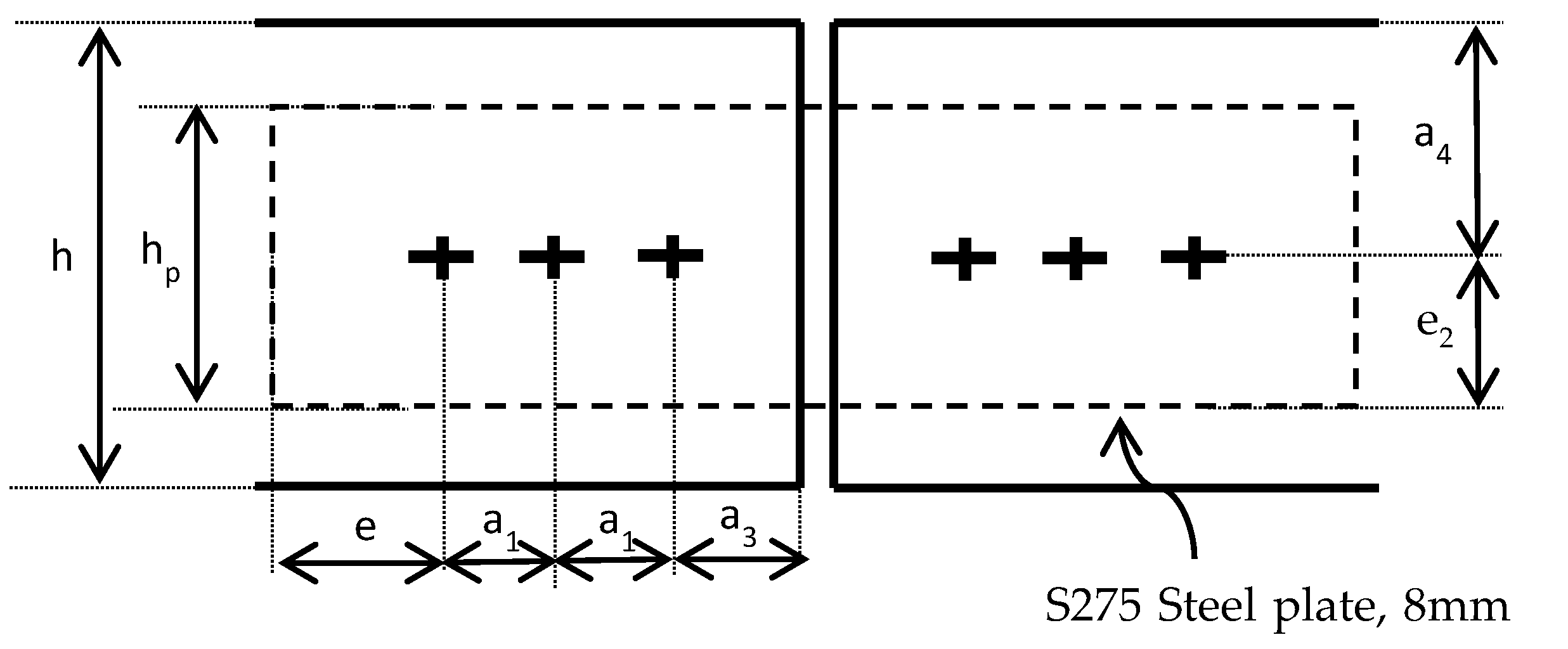
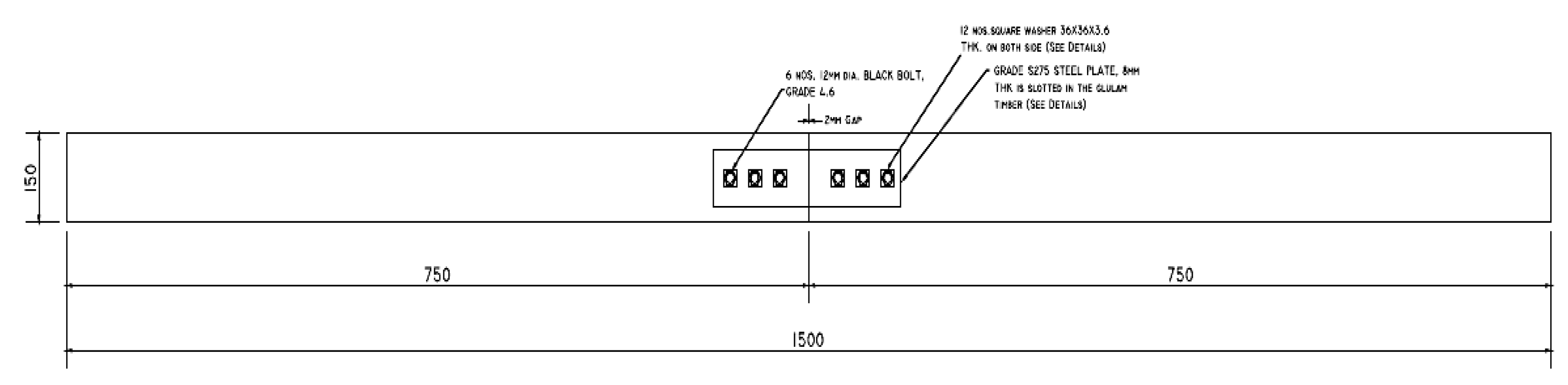
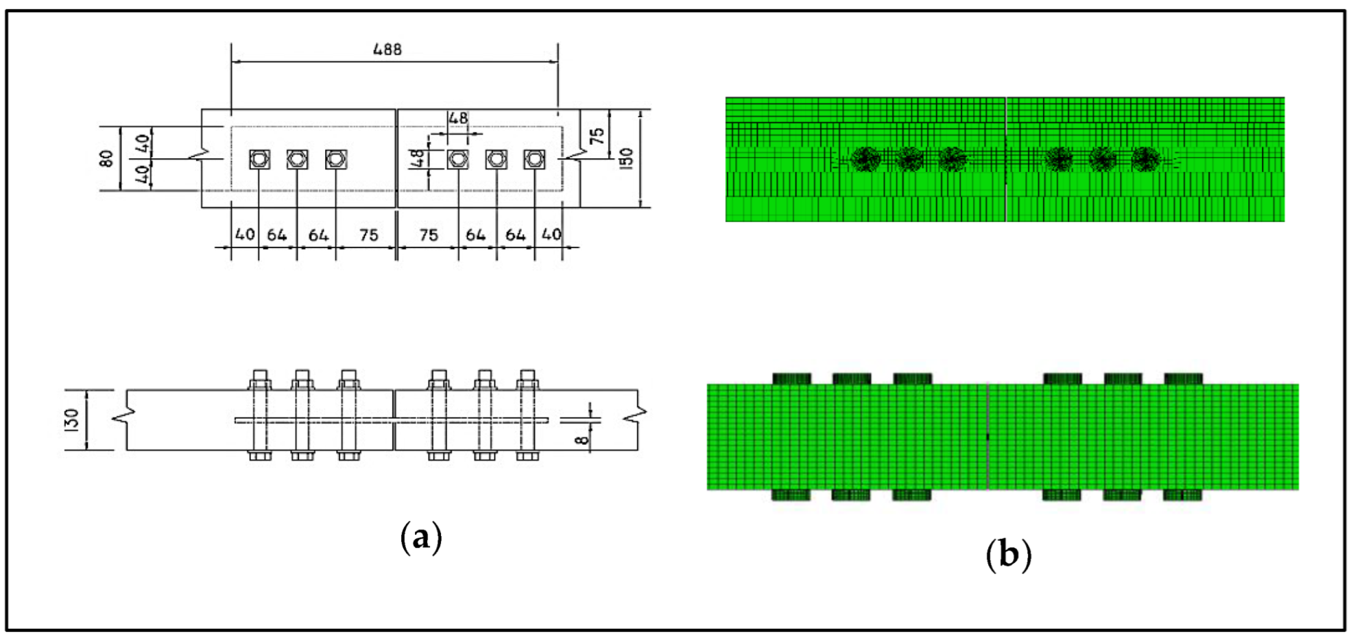
2.1. Specimen Design

Configurations of the test samples are shown in Figure 1. Mengkulang timber species was selected to manufacture the glulam timber beam for the tests, with a measured moisture content of 8.65%. Material tests for the Mengkulang timber were carried out in advance according to BS EN 392:1995 [27], MS 758:2001 [28], and ASTM-D5764-97 [29], and the results of the material tests were used as the input for the numerical models. The diameter of the bolts, the spacing, end distance, and edge distance of the bolts satisfy the requirements specified in BS EN1995-1-1 [2] and BS EN1995-1-2 [3]. The bolts and the slotted-in steel plate material were mild steel with a yield strength of 275 MPa. The slotted-in steel plate has a thickness of 8 mm. The design of the bolted connection and other specifications, such as dimensions and configuration, were made according to the previous research [18,21,26,30] and current timber connection standard ASTM D198-14:2014 [31] and MS544-5:2017 [32]. Table 1 shows the configurations of glulam beam bolted spliced connections. In this study, six (6) glulam timber beam samples of similar geometrical configurations were tested. All samples were tested at normal temperature under a four-point bending load until failure. Three (3) samples were tested without exposure to the standard fire, and the other three (3) samples were tested at normal temperature after exposure to the standard fire for 30 min. As shown in Figure 2, the geometrical dimensions for the glulam timber beams were set as 130 mm × 150 mm × 1500 mm with five (5) laminations to provide a total height of 150 mm, and the bolted spliced connections were set at the midspan.

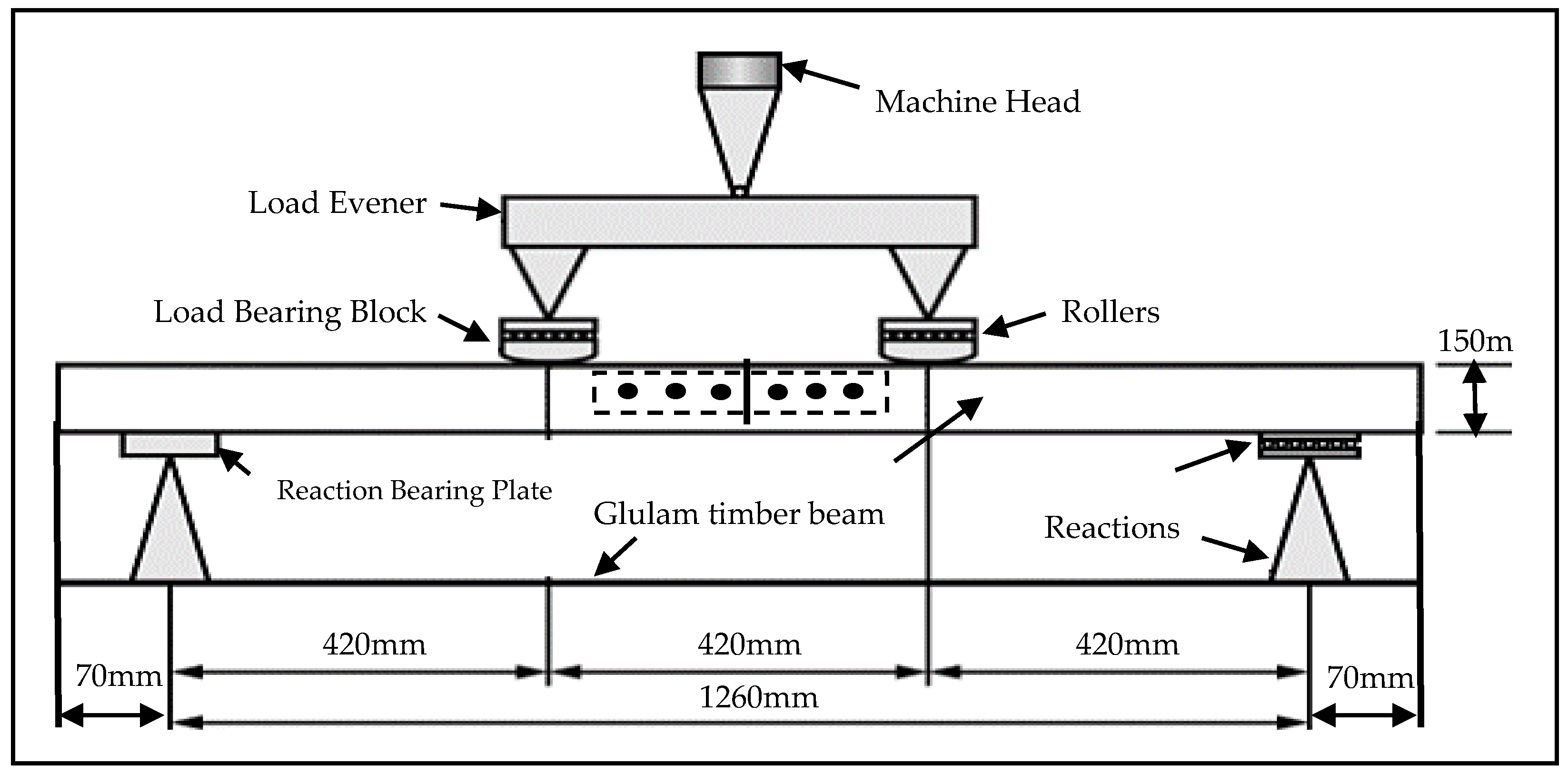
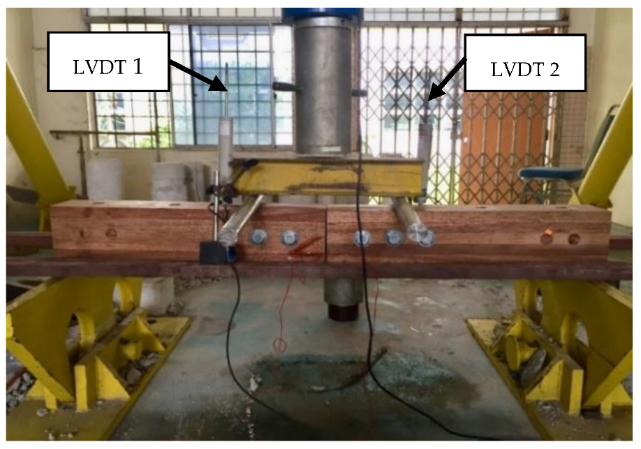
2.2. Tests at Normal Temperature before Exposure to Standard Fire

Six (6) glulam timber beams bolted spliced connection samples were prepared for a four-bending test, according to ASTM D198-14:2014 [31]. Two (2) numbers of linear voltage displacement transducers (LVDT) were mounted on the glulam timber beam to measure the respective vertical beam deflection under the point loads. The beam was deflected at a prescribed rate of 0.1 kN/s, and coordinated observations of loads and deflections were made until rupture failure. A similar test setup for four-point bending before and after exposure to the standard fire was performed. The test setup is shown in Figure 3 and Figure 4.

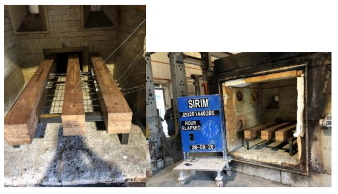
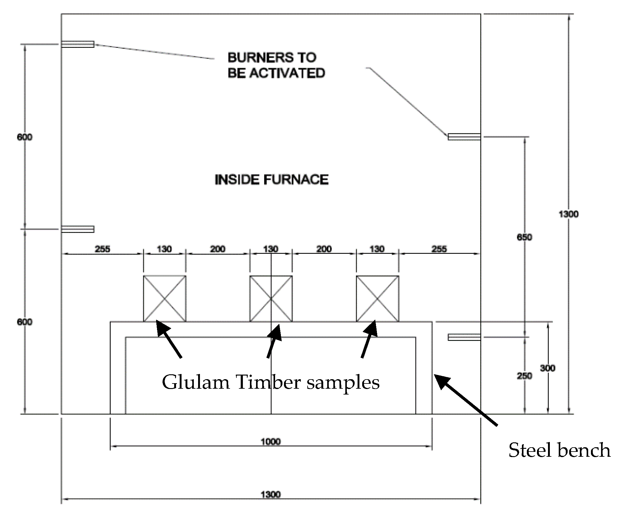
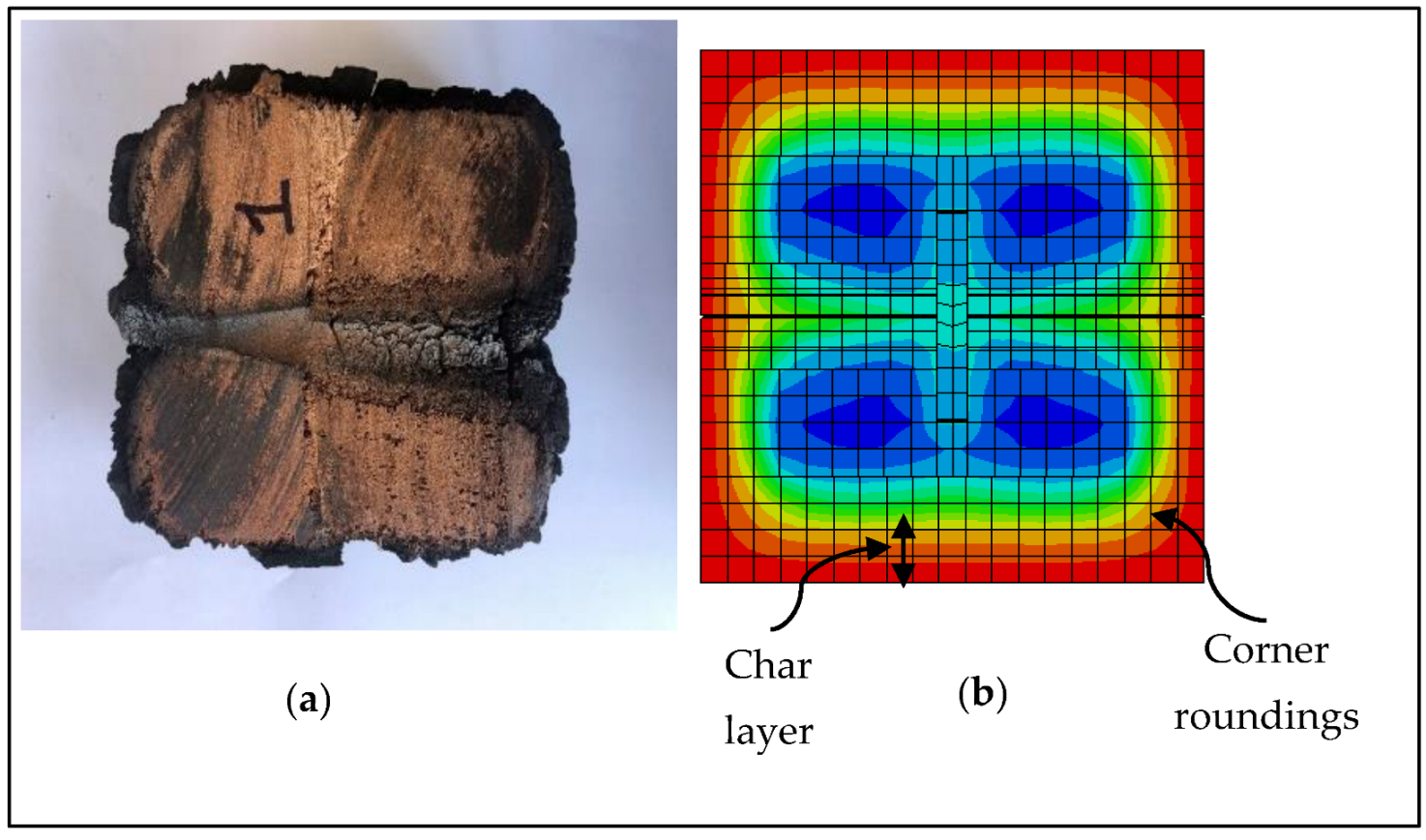
2.3. Exposure to Standard Fire

Three (3) glulam timber beam samples were exposed to standard fire for 30 min to allow the timber to reach 300 °C isotherm to develop a charred layer [18,33,34], as shown in Figure 5 and Figure 6. The arrangement of the glulam timber beam samples, the procedures, and specifications for the charring rate’s determination was according to BS 476-20:1987 [35], BS 476-21:1987 [36], and NDS TR-10:2018 [37]. The glulam timber beam samples were arranged to allow four (4) dimension fire exposure (4D).
The exposure duration was determined according to the temperature-time relationship equation specified in BS 476-20:1987 [35] (Equation (2)).
T = 345 l o g 10 8 t + 1 + 20
where:
T is the furnace’s temperature, t is the time in a minute, and 20 is the furnace’s initial temperature. After 30 min, the samples were taken out and cooled with water to avoid further charring [38]. The samples were then wrapped with plastic foil to prevent airflow, stopping further combustion [33,39,40].
The charring rate was calculated based on the simplified method specified in NDS TR-10:2018 [37], which uses the charring depth value measured from the residual glulam timber sample section. Equations (3) and (4) were used to calculate the charring rate based on the charring depth and the fire exposure time.
d c h a r = b o r i g i n a l b r e s i d u a l 2
β = d c h a r t
where:
  • boriginal = original timber section width
  • bresidual = residual timber section width
  • dchar = charring depth with corner roundings effect
  • t = time in fire exposure
  • β = charring rate

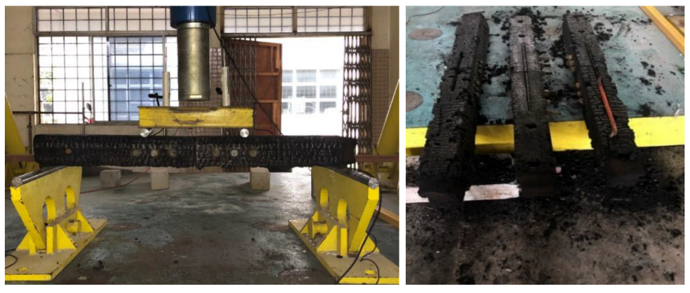
2.4. Tests at Normal Temperature after Exposure to Standard Fire

The only difference with the four-point bending test before exposure to the standard fire is that the after-fire bending test was performed after the samples were exposed to standard fire for 30 min and cooled down to normal temperature. The samples were prepared for the four-point bending test with the charred layer still left intact with the residual cross-section to simulate the glulam timber beam’s actual state after the fire event. The test setup is shown in Figure 7.

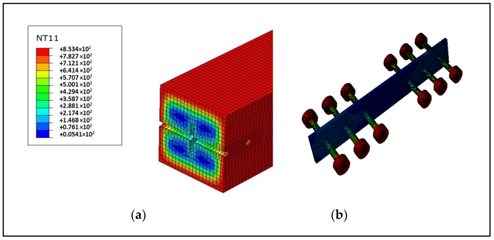
2.5. Numerical Simulations

In this study, numerical models in normal temperature and fire were performed as presented in Section 2.5.1 and Section 2.5.2, respectively.

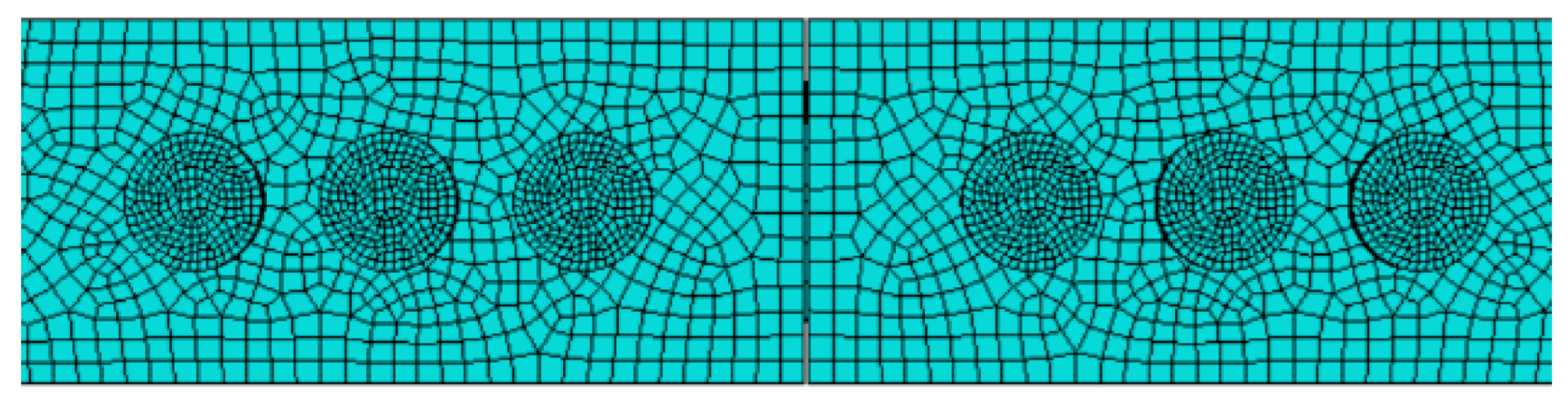
2.5.1. Numerical Models in Normal Temperature

A 3D finite element model (FEM) of the glulam timber beam bolted spliced connection was generated using Abaqus [41]. Then, the accuracy of the model was validated by the experimental tests. The accuracy of FEM simulations depends on the model’s complexity and the available data, such as material parameters, constitutive models, and failure criteria. Most finite element models assume ductile elastic-plastic behavior in compression and brittle elastic behavior in tension and shear. Some researchers assume linear-elastic perfectly-plastic compression [33,42,43,44,45,46,47]. Others include softening and hardening in grain directions [21,44,48]. In tension and shear, failure is typically handled by softening the material after failure requirements are achieved [43]. Most works employ continuum damage mechanics; however, fracture models are sometimes used [25,49].
In principle, the stresses and the strains of an orthotropic material are related to the basic principle of stress (σ), strain (ε), and modulus of elasticity (E) relationship in Equation (5).
σ = E ε
In this study, glulam timber is modeled as an orthotropic material. The elasticity of material in Equation (5) can be rewritten into a 6x6 matrix form with nine (9) orthotropic elastic constants shown in Equation (6) [50] to account for three perpendicular axes of elastic symmetry at each point in the material.
{σ} = [D]ortho {ε}
where:
{σ} = stress tensor
{ε} = strain tensor
[D] = orthotropic elastic matrix (6 × 6)
D = 1 E 1 ν 21 E 2 ν 31 E 3 0 0 0 0 1 E 2 ν 32 E 3 0 0 0 0 0 1 E 3 0 0 0 0 0 0 1 G 12 0 0 0 0 0 0 1 G 23 0 0 0 0 0 0 1 G 31
The value of E1 of 10,800 N/mm2 was obtained from MS 544: Part 3: 2001 [51] for the mean modulus of elasticity for glulam Mengkulang timber (D40). The other elastic constants values, such as E2, E3, ν21, ν31, ν32, G12, G23, and G31 were determined based on the recommended ratios by Ahmad [42] as shown in Equations (7) and (8) for tropical hardwood timber. The Poisson’s ratio value parallel to the timber grain of 0.026 was taken from Ahmad [42] for tropical hardwood timber. The value of Poisson’s ratio perpendicular to the grain in the same plane was calculated using the relationship in Equation (9) (Green and Winandy [52]). Other values for Poisson’s ratio for timber, i.e., v32 = 0.35, v12 = v13 = 0.015, as considered by Ahmad [42]. These values are within the realistic margins of 0.15 < v32 < 0.4, 0.01 < v13 < 0.03, and 0.01 < v12 < 0.06 reported in the previous study [52].
E 1 E 2 = 11.5
E 1 G 12 = 16
ν 12 E 1 = ν 21 E 2
The glulam timber was also modeled as having elastoplastic behavior, as exhibited in the experimental data. In Abaqus, the elastoplastic data are defined as the true yield stress of the material as a function of true plastic strain. The standard value of 210,000 N/mm2 for Young’s modulus and 0.3 for Poisson’s ratio were used for the steel material. The washers were not generated between nut and timber in this model. The detailed mechanical properties of glulam Mengkulang timber are as in Table 2.
The various parts of the FEM (Figure 8) were generated individually based on specified geometric parameters used in the experimental test. The generated parts were assembled, with a specified general contact interaction between parts assigned to simplify the modeling. There were two main components in the general interactions assigned. The first component is normal behavior with hard contact to avoid intersecting errors between FEM parts. The second is tangential behavior to establish the friction of 0.3 value between FEM parts. In modeling the tested connections, the tolerances of +3 mm and +0.1 mm were considered between the surface of the bolts and the bolt holes surface in the timber member and the steel plate. The mesh was controlled by specifying global and local mesh constraints for the various parts of the model. Element sizes varied throughout the different regions of each part of the model, i.e., the steel plate and timber member, controlled by setting global element sizes for the different parts based on the overall dimensions of each part and imposing mesh size constraints along the edges based on the relevance of each edge, i.e., edges with expected high stress or temperature gradients were assigned with finer meshes. Edges around fastener holes were seeded with constraints enforcing smaller element sizes. In contrast, edges farther away were seeded with larger element sizes, such as the horizontal edges of the end of the timber. The element type DC3D8R, an 8-node linear hexahedron for heat transfer, was used in the generated meshes (Figure 9).
Following these procedures, the four-point bending test was set up. It consists of an initial step for setting the boundary conditions using pin and roller supports. Another step was set up to simulate the concentrated load. It includes the automatic incremental load, an initial concentrated load of 5 kN to allow the model to get into a locked-in position. The iteration number was set to 1000, with an incrementation size of 0.01, a minimum value of 0.0001, and a maximum value of 0.1 to avoid convergence error. The non-linear geometric was chosen, and the other values were set by default was performed. The comparison between FEM results and experimental data is shown in Table 3.

2.5.2. Numerical Models in Fire

Numerical models of heat transfer were performed in this study. The thermal actions on the standard fire exposed surfaces followed EN 1991-1-2:2002 [53], for the gas temperature followed the standard time-temperature curve of BS 476-20:1987 [35]. The net heat flux, ˙hnet includes the net convective heat flux, hnet,c and radiative heat flux, h net,r as shown in Equation (10):
hnet = hnet,c + hnet,r
The net convective heat flux hnet,c is calculated by:
hnet,c = acg − θm)
where ac is the convection coefficient and is equal to 25 W·m−2·K−1 [54]; θg and θm are gas temperature [°C] and surface temperature [°C], respectively.
The radiative heat flux hnet,r is calculated by:
hnet,r = Φ · εm · εf · σ [(θr + 273)4 − (θm + 273)4]
where Φ is the configuration factor of the exposed surface and is equal to 1 [54]; εm is the emissivity and is set as 0.8 [54] for wood and 0.7 for steel [54]; εf is the emissivity of the fire and is set as 1 [54]; σ is the Stephan Boltzmann constant and is set as 5.67 × 10⁻⁸ W·m−2·K−4 [54]. θr and θm are effective radiation temperature [°C] and surface temperature [°C], respectively.
The thermal actions were specified as the amplitude loading simulating the specified standard time-temperature fire curve generated using Equation (2). At the timber contact surface with the bolt, the heat transfer was assumed to be orthotropic to account for heat transfer to the surrounding timber surface in all directions. Thermal conductivity values parallel to the grain were calculated as four times the conductivity perpendicular to the grain as specified in EN1995-1-2:2004 [3] temperature-conductivity curve [55]. Specific heat capacity and density are not directionally dependent, and the specific heat capacity values are for timber with an initial moisture content of 12%. However, the values can be related to other initial moisture content [56]. The density at 20 °C (normal temperature) was assumed to be the mean value for glulam of strength grade D40, that is ρmean,20°C = 700 kg/m3, based on MS 544: Part 3: 2001 [51]. The physical and thermal properties assigned to the steel components were referred from the fire standard code for steel design EN 1993-1-2:2011 [57]. The yield stress values of 240 N/mm2 and 275 N/mm2 were used for mild steel bolts and S275 steel plates.
In this study, the FEM model was composed of several parts assembled with and without gaps between them. Thus, the heat transfer between parts was modeled by defining thermal contact interactions. In generating the FEM model for heat transfer, the thermal contact interactions were divided into two parts. The first part was modeling the standard fire exposure using surface film condition and surface radiation interactions set on all four sides of the glulam timber beam and the bolted connection, with the timber convection coefficient of 25 W/m2K and the standard temperature-time curve modeled as an amplitude. The second part was modeling the heat transfer between the different parts by defining the thermal contact conductance as a function of the gap clearance since the thermal contact conductance was observed to increase with the increasing interface pressure and the decreasing surface roughness [7]. The thermal contact interaction was modeled not to have a temperature drop for the contact between parts with no gap and no heat transfer between the contacting surfaces with a gap of at least 2 mm. Therefore, the gap conductance coefficient was equal to 1000 mW/mm2K for contact with no gap and 0 mW/mm2K if the surface gap was more than 2 mm [7]. A linear variation of the gap conductance coefficient was assumed for intermediate clearances between the surfaces.

3. Results

Table 4 summarizes the charring depth and charring rate for this experimental work and other authors’ data. In addition, the value from EC5-1-2:2004 for glulam hardwood timber is also included for comparison. Comparing the results between this experiment and the secondary data from Daud et al. [58], the charring rate of glulam Mengkulang is higher than glulam Keruing (Dipterocarpus C.F.Gaertn.) and Malagangai (Potoxylon melagangai (Symington) Kosterm.) by 22.80 % and 21.05 %, respectively. However, this experiment’s charring rate is identical to the value specified in EN 1995:1-2:2004 [3]., with a percentage difference of 3.05 %.
A typical failure for beams is in a brittle failure pattern, seen in crack lines propagating from the bolt hole to the beam’s other end, causing timber splitting longitudinally. A further inspection performed after the bending test showed a slight yielding in the bolts, indicating that the timber char layer effectively acted as thermal insulation to the inner timber section from further charring (Figure 10), keeping the temperature below 100 °C thus protecting the bolt during exposure to the standard fire.

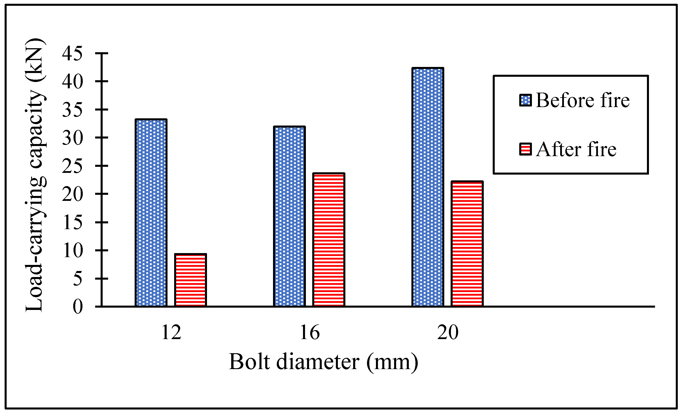
3.1. Comparison of Bending Strength before and after Fire

The comparison of bending strength for the glulam timber beam bolted connection tested at normal temperature before and after the standard fire exposure is shown in Table 3. However, the glulam timber samples protected the bolts and the slotted-in steel plate from excessive heat above 100 °C and secured from further strength loss. Referring to Figure 11, the glulam timber beam samples with 12 mm bolted connection show the highest reduction of the load-carrying capacity of 71.8%. The two other glulam timber bolted connections of 16 mm and 20 mm also show the reduction but not as high, 26.1% and 47.6%, respectively.

3.2. Model Validation

The glulam timber beam bolted connections tested at normal temperature before and after exposure to the standard fire (Figure 12) were further used to validate the FEM models for further parametric study analysis. The validation investigated the temperature gradient in the timber, bolts, and slotted-in steel plate and the lateral load-carrying capacity under bending after 30 min of exposure to the standard fire. The formation of the charred layer developed in the experimental glulam timber beam section was compared to the simulated FEM model. It can be seen from Figure 4 that a similar pattern with the roundings’ was developed at the corners of the FEM model. Table 5 shows a difference of 3.5% between the experimental and the FEM model. Thus, the resulting outcome from the FEM model is validated.

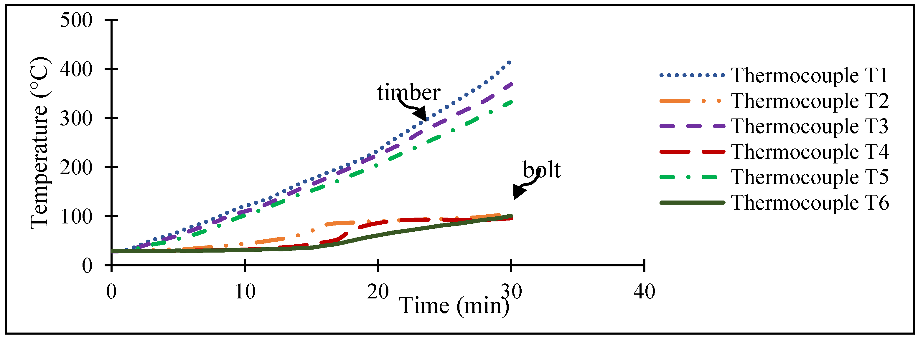
3.3. Validation Based on Temperature Gradient in the Bolt and Timber

This section compared the temperature changes in bolt and timber from the FEM model with the experimental results. From Figure 13, the temperature on the timber surface and the exposed bolts in the deformed FEM model is above 850 °C, while the inner timber section at 30 mm depth remains below 450 °C. The bolts and steel plate temperature inside the timber remains below 100 °C. Comparing the experimental and FEM model results shows an identical temperature gradient pattern. Thus, the FEM model is validated.

3.4. Influence of Member Thickness

As observed in the numerical analyses, the member thickness is the most critical parameter influencing the fire resistance of timber connections loaded perpendicular to the grain direction. Therefore, a parametric study was conducted to evaluate the influence of varying the member thickness on the tested connections’ fire resistance in the direction perpendicular to the grain.
Five (5) thicknesses were selected: b-40, b-30, b-20, b, b+20, where b = 130 mm of the tested 30-min standard fire exposure for a bolt diameter of 16 mm. The results of these simulations (Table 6) show the influence of the side member thickness on the load-carrying capacity before and after exposure to the standard fire. The slight difference between the FEM and experimental results can be due to the tolerance adopted for the bolt holes. In the FEM, the tolerance of the bolt holes was kept. However, in the experimental tests, there was contact between the bolt and the surfaces of the holes. Other factors can be due to timber’s thermal-dependent physical and mechanical properties based on the hardwood specified in EN 1995-1-2 [3]. Thus, inaccuracies occur.

3.5. Simplified Rules-Unprotected Timber-to-Timber Connections

In the simplified rules for exposed timber-to-timber connections, it is assumed that connections are designed per EN 1995:1-2: 2004 [3] satisfy a fire resistance of 15 min (for nails, screws, bolts, and connectors) or 20 min (for dowels), provided that a minimum side member thickness is utilized. For connections made with fasteners that have non-projecting heads (such as nails, screws, and dowels), fire resistances that are greater than those assumed for connections made with the minimum end and edge distances prescribed by design at a normal temperature per EN 1995-1-1:2004 [2], may be accomplished if the thickness of the side members, denoted by t1, as well as the end lengths and edge distances of the fasteners, denoted by a3 and a4, respectively, are raised by the factor afi indicated in Equation (13).
afi = βn · kflux · (treqtfi)
where: βn is the notional charring rate, kflux = 1.5 is a coefficient to consider the increased heat flux through the fasteners, treq is the required fire resistance, and tfi is the fire resistance of the unprotected connection (treq = 15 or 20 min, as mentioned above).
Calculation of the characteristic load-carrying capacity of an unprotected connection with fasteners in shear and side members of timber after a given period of standard fire exposure should be done per Section 6.2.2 of EN 1995-1-2:2004 [3], which states that the equation for this calculation should be as follows (14):
Fv,Rk,fi = e−k·td,fi · Fv,Rk
where: Fv,Rk is the characteristic load-carrying capacity of the connection at normal temperature calculated according to EN 1995-1-1:2004 [2]. k is a parameter describing the reduction of the load-carrying capacity for different connection configurations, and td, fi is the design fire resistance of the unprotected connection. For consistency between EN 1995-1-1:2004 [2] and EN 1995-1-2:2004 [3], the load-carrying capacity of a connection is denoted as R instead of Fv, which in EN 1995-1-1:2004 [2] represents the load-carrying capacity per shear plane per fastener and not the load-carrying capacity of the connection specified in EN 1995-1-2:2004 [3].

3.6. Modification Proposal

A simple way to modify the reduced load method is to make the parameter k dependent on the timber member b, which is the most relevant parameter regarding the fire resistance of timber connections. Therefore, the load-carrying capacity of the glulam timber beam bolted connection after a given period of fire exposure Rfi can be calculated using Equation (15).
Rfi = e−k·tfi · R20°C
where R20°C is the load-carrying capacity at normal temperature and the exponential decay constant k as a function of member thickness, b can be written (Equation (16)),
k = k(b) = c1 + c2 · b
where c1 and c2 are regression parameters specific for bolted connection, and b is the thickness of the glulam timber members.
The parameters c1 and c2 for the bolted connection (Table 7) were obtained by fitting a negative one-parameter exponential model to data subsets comprising experiments with the different member thicknesses, therefore getting an exponential decay constant k for each member thickness, b. A simple linear model was then fitted to the obtained decay constants parameters.

4. Conclusions

This research enhances the understanding of the performance of the structural glulam timber beam connected with bolts and a slotted-in plate. Given the comments and conclusion presented throughout this study, the research has resulted in the following conclusions. The mechanical properties of bolts and glulam timber were successfully determined before and after the fire exposure. The bolt’s toughness, strength, stiffness, and ductility were significantly reduced after exposure to the standard fire. The bolt withdrawal strength was affected by the bolt diameter, and the bolt diameter has a negative relation to the withdrawal strength. The charring rate of Mengkulang glulam timber was close to the value specified in EN1995-1-2:2004 [3] but slightly better than the values reported by the previous author on other tropical timber species.
Overall results on the double shear test for determining the load-carrying capacity in tensile load showed that the failure mode was significantly affected by the bolt diameter. The larger bolt caused a brittle failure occurred in the connection. The load-carrying capacity for the double shear test under a four-point bending load before the fire exposure showed that the bolt diameter negatively relates to the timber connection ductility but positively relates to the timber load-carrying capacity. The load-carrying capacity of the glulam timber beam after exposure to the fire is influenced by the glulam timber thickness. All failure after exposure to the fire was brittle, proving that bolt diameter has less influenced the load-carrying capacity of the glulam timber beam.
The numerical analyses for validating and predicting the load-carrying capacity of the glulam timber beam with different glulam timber thicknesses are reliable and sufficient. The EYM equation specified in EN1995-1-2:2004 [3] does not include timber thickness as the influenced factor. Therefore, the modified decay constant under bending load after exposure to fire is proposed.

Author Contributions

Conceptualization, R.H. and M.N.S.; methodology, M.N.S.; software, M.N.S. and W.C.L.; validation, N.H.A.H. and N.J.A.M.; formal analysis, M.N.S.; investigation, M.N.S. and N.J.A.M.; resources, A.Z.; data curation, M.N.S.; writing—original draft preparation, M.N.S. and A.A.; writing—review and editing, M.S.S.; visualization, M.N.S. and W.C.L.; supervision, R.H.; project administration, R.H.; funding acquisition, R.H. All authors have read and agreed to the published version of the manuscript.

Funding

This research was funded by the Ministry of Higher Education (MOHE) Malaysia, Grant number: FRGS/1/2015/TK01/UITM/02/9.

Data Availability Statement

Not applicable.

Acknowledgments

All authors would like to express utmost gratitude to Universiti Teknologi MARA, Malaysia, and the Ministry of Higher Education (MOHE) Malaysia for the financial support contributed through Fundamental Research Grant Scheme (FRGS) (FRGS/1/2015/TK01/UITM/02/9).

Conflicts of Interest

The authors declare no conflict of interest.

References

  1. MS 544-9; Fire-Resistance of Timber Structures: Section 1: Method of Calculating Fire Resistance of Timber Members. Department of Standards Malaysia. SIRIM: Shah Alam, Malaysia, 2001.
  2. EN 1995-1-1; Design of Timber Structures Part 1 (Vol. 144, Issue 6). European Committee for Standardization: Brussels, Belgium, 2004.
  3. EN 1995:1-2; Eurocode 5: Design of Timber Structures. European Committee for Standardization: Brussels, Belgium, 2004.
  4. Awaludin, A.; Astuti, P. Study on Utilization of LVL Sengon (Paraserianthes falcataria) for Three-Hinged Gable Frame Structures. Int. J. Eng. Technol. Innov. 2016, 6, 232–241. [Google Scholar]
  5. EN 14080; Standards Publication Timber Structures—Glued Laminated Timber and Glued Solid Timber—Requirements. European Committee for Standardization: Brussels, Belgium, 2014.
  6. König, J.; Fontana, M. The performance of timber connections in fire-test results and rules of Eurocode 5. In Proceedings of the International RILEM Symposium, Stuttgart, Germany, 10–12 September 2001; pp. 639–648. [Google Scholar]
  7. Palma, P.; Frangi, A. Simplified mechanical models for timber connections in fire. Compwood 2019, 107, 54–74. [Google Scholar]
  8. Norén, J. Load-bearing capacity of nailed joints exposed to fire. Fire Mater. 1996, 20, 133–143. [Google Scholar] [CrossRef]
  9. Kruppa, J.; Lamadon, T.; Rachet, P. Fire resistance test of timber connections. In CTICM Ref. INC-00/187-JK/NB; CTICM: Paris, France, 2000. [Google Scholar]
  10. Fleischer, H.; Fornather, J.; Bergmeister, K.; Luggin, W. Large Fire Test Series 1—GBV 1—Tests on Timber Connections with Dowels; Universität für Bodenkultur Wien: Vienna, Austria, 2002; p. 54. [Google Scholar]
  11. Scheer, C. Load-bearing capacity of wood connections with pin-shaped fasteners in the event of fire. Part 2: Fire tests to confirm the theoretical knowledge; Technische Universität Berlin: Berlin, Germany, 2004; ISBN 3-8167-6876-8. [Google Scholar]
  12. Oksanen, T.; Kevarinmaki, A.; Yli-Koski, R.; Kaitila, O. Fire resistance on timber connections with stainless steels, Work 29; VTT Information Service: Espoo, Finland, 2015; ISBN 951-38-6589-4. [Google Scholar]
  13. Erchinger, C.; Frangi, A.; Fontana, M. Fire design of steel-to-timber dowelled connections. Eng. Struct. 2010, 32, 580–589. [Google Scholar] [CrossRef]
  14. Laplanche, K.; Dhima, D.; Racher, P. Thermo-Mechanical Analysis of the Timber Connection under Fire Using 3D Finite Element Model. In Proceedings of the 9th World Conference on Timber Engineering 2006, WCTE 2006, Portland, OR, USA, 6–10 August 2006; Volume 1, pp. 279–286. [Google Scholar]
  15. Lau, P. Fire Resistance of Connections in Laminated Veneer Lumber (LVL). Master’s Thesis, University of Canterbury, Christchurch, New Zealand, 2006. [Google Scholar]
  16. Chuo, T.C. Fire Performance of Connections in Laminated Veneer Lumber (LVL). Master’s Thesis, University of Canterbury, Christchurch, New Zealand, 2007. [Google Scholar]
  17. Peng, L.; Hadjisophocleous, G.; Mehaffey, J.; Mohammad, M. Fire performance of timber connections, part 1: Fire resistance tests on bolted wood-steel-wood and steel-wood-steel connections. J. Struct. Fire Eng. 2012, 3, 107–131. [Google Scholar] [CrossRef]
  18. Audebert, M.; Dhima, D.; Taazount, M.; Bouchaïr, A. Thermo-mechanical behaviour of timber-to-timber connections exposed to fire. Fire Saf. J. 2013, 56, 52–64. [Google Scholar] [CrossRef]
  19. Werther, N.; O’Neill, J.W.; Spellman, P.M.; Abu, A.K.; Moss, P.J.; Buchanan, A.H.; Winter, S. Parametric Study of Modelling Structural Timber in Fire with Different Software Packages. In Proceedings of the 7th International Conference on Structures in Fire, Zurich, Switzerland, 6–8 June 2012; pp. 1–10. [Google Scholar]
  20. Palma, P. Fire Behaviour of Timber Connections. Ph.D. Thesis, Technical University of Lisbon, Lisbon, Portugal, 2016. [Google Scholar]
  21. Audebert, M.; Dhima, D.; Taazount, M.; Bouchaïr, A. Numerical investigations on the thermo-mechanical behaviour of steel-to-timber joints exposed to fire. Eng. Struct. 2011, 33, 3257–3268. [Google Scholar] [CrossRef]
  22. ASTM E119; Standard Test Methods for Fire Test of Building Construction and Materials. American Society for Testing and Materials: West Conshohocken, PA, USA, 2000.
  23. ISO 834-1; Fire-Resistance Tests—Elements of Building Construction—General Requirements. International Organization for Standardization: Geneva, Switzerland, 1999.
  24. Petrycki, R.; Salem, O. Structural fire performance of wood-steel-wood bolted connections with and without perpendicular-to-wood grain reinforcement. J. Struct. Fire Eng. 2019. [Google Scholar] [CrossRef]
  25. Audebert, M.; Dhima, D.; Bouchaïr, A. Proposal for a new formula to predict the fire resistance of timber connections. Eng. Struct. 2019, 204, 1–18. [Google Scholar] [CrossRef]
  26. Anshari, B.; Guan, Z.W.; Wang, Q.Y. Modelling of glulam beams pre-stressed by compressed wood. Compos. Struct. 2017, 165, 160–170. [Google Scholar] [CrossRef] [Green Version]
  27. EN 392; Glued Laminated Timber—Shear Tests of Glue Lines. European Committee for Standardization: Brussels, Belgium, 1995.
  28. MS 758; Glued Laminated Timber—Performance Requirements and Minimum Production Requirements. Malaysian Standard: Cyberjaya, Malaysia, 2001.
  29. ASTM D5764-97; Standard Test Method for Evaluating Dowel-Bearing Strength of Wood and Wood. American Society for Testing and Materials: West Conshohocken, PA, USA, 2002.
  30. Moss, P.; Buchanan, A. Fire performance of bolted connections in laminated veneer lumber. Fire Mater. 2009, 33, 223–243. [Google Scholar] [CrossRef] [Green Version]
  31. ASTM D198-14; Standard Methods of Static Tests of Lumber in Structural Sizes. American Society for Testing and Materials: West Conshohocken, PA, USA, 2014.
  32. MS 544-5; Timber Joints. SIRIM: Shah Alam, Malaysia, 2017.
  33. Brandon, D. Fire and Structural Performance of Non-Metallic Timber Connections. Ph.D. Thesis, University of Bath, Bath, UK, 2015. [Google Scholar]
  34. Dârmon, R.; Lalu, O. The fire performance of cross-laminated timber beams. Procedia Manuf. 2019, 32, 121–128. [Google Scholar] [CrossRef]
  35. BS 476-20; Fire Tests on Building Materials and Structures. Method for determination of the fire resistance of elements of construction (general principles) (AMD 6487). British Standards Institution: Loughborough, UK, 1987.
  36. BS 476-21; Fire Resistance Test to Building Material—Loadbearing elements. British Standards Institution: Loughborough, UK, 1987.
  37. NDS TR-10:2018; National Design Specification for Wood Construction. American Wood Council: Leesburg, VA, USA, 2018.
  38. Buchanan, H.; King, A.B. Fire performance of gusset connections in glue—laminated timber. Fire Mater. 1991, 15, 137–143. [Google Scholar] [CrossRef]
  39. Chorlton, B.; Harun, G.; Gales, J.; Weckman, E.; Smith, M. An Investigation Into the Resilience of Glulam Timber Beams after Fire Exposure. In Proceedings of the 6th International Structural Specialty Conference 2018, Held as Part of the Canadian Society for Civil Engineering Annual Conference, Fredericton, Canada, 13–16 June 2018; pp. 655–664. [Google Scholar]
  40. Quiquero, H.; Chorlton, B.; Gales, J. Performance of adhesives in glulam after short term fire exposure. Int. J. High-Rise Build. 2018, 7, 299–311. [Google Scholar]
  41. Abaqus; Version 2021; Dassault Systemes: Vélizy-Villacoublay, France, 2021.
  42. Ahmad, Y. Bending Behaviour of Timber Beams Strengthened Using Fibre Reinforced Polymer Bars and Plates. Ph.D. Thesis, University Teknologi Malaysia, Johor Bahru, Malaysia, 2010. [Google Scholar]
  43. Monteiro, S.R.S.; Martins, C.; Dias, A.M.P.G.; Cruz, H. Mechanical performance of glulam products made with Portuguese poplar. Eur. J. Wood Wood Prod. 2020, 78, 1007–1015. [Google Scholar] [CrossRef]
  44. Racher, P.; Laplanche, K.; Dhima, D.; Bouchaïr, A. Thermo-mechanical analysis of the fire performance of dowelled timber connection. Eng. Struct. 2010, 32, 1148–1157. [Google Scholar] [CrossRef]
  45. Shakimon, M.N.; Abd Malek, N.J.; Hassan, R.; Ahmad, A. The finite element modelling of glulam. J. Teknol. 2016, 78, 75–78. [Google Scholar]
  46. Suhaimi, T. Factors affecting ultimate strength of solid and glulam timber beams. J. Kejuruter. Awam 2004, 16, 38–47. [Google Scholar]
  47. Xu, H.; Taazount, M.; Bouchaïr, A.; Racher, P. Numerical 3D finite element modelling and experimental tests for dowel-type timber joints. Constr. Build. Mater. 2009, 23, 3043–3052. [Google Scholar] [CrossRef]
  48. Wang, M.; Song, X.; Gu, X.; Tang, J. Bolted glulam beam-column connections under different combinations of shear and bending. Eng. Struct. 2019, 181, 281–292. [Google Scholar] [CrossRef]
  49. Kováčiková, J.; Ekevad, M.; Ivánková, O.; Berg, S. Finite Element Analysis of Timber Beams with Flaws. In Proceedings of the 7th European Congress on Computational Methods in Applied Sciences and Engineering, Crete Island, Greece, 5–10 June 2016; pp. 8606–8611. [Google Scholar]
  50. Mascia, N.T.; Lahr, F.A.R. Remarks on orthotropic elastic models applied to wood. Mater. Res. 2006, 9, 301–310. [Google Scholar] [CrossRef] [Green Version]
  51. MS 544 Part 3; Glued Laminated Timber. Department of Standards Malaysia: Selangor, Malaysia, 2001.
  52. Green, D.W.; Winandy, J.E. Mechanical Properties of Wood. In Wood Handbook: Wood as an Engineering Material; Forest Department of Agriculture: Washington, DC, USA, 1999. [Google Scholar]
  53. EN 1991-1-2:2002; Eurocode 1. Actions on structure—General actions. Actions on structures exposed to fire. European Committee for Standardization: Brussels, Belgium, 2011.
  54. Luo, J.; He, M.; Li, Z.; Gan, Z.; Wang, X.; Liang, F. Experimental and numerical investigation into the fire performance of glulam bolted beam-to-column connections under coupled moment and shear force. J. Build. Eng. 2022, 46, 103804. [Google Scholar] [CrossRef]
  55. Paulo, B.C.; Jean-Marc, F. Comparison between the charring rate model and the conductive model of Eurocode 5. Fire Mater. 2009, 33, 129–143. [Google Scholar]
  56. Cachim, P.B.; Franssen, J.M. Assessment of Eurocode 5 charring rate calculation methods. Fire Technol. 2010, 46, 169–181. [Google Scholar] [CrossRef]
  57. EN 1993-1-2; Design of Steel Structures—Part 1–2: General Rules—Structural Fire Design. European Committee for Standardization: Brussels, Belgium, 2011.
  58. Daud, F.; Ahmad, Z.; Hassan, R. Charring rate of glued laminated timber (glulam) made from selected Malaysian tropical timber. In InCIEC 2014, Proceedings of the International Civil and Infrastructure Engineering Conference 2014, Kota Kinabalu, Sabah, 28 September–1 October 2015; Springer: Singapore, 2015; pp. 1107–1116. [Google Scholar]
Figure 1. Typical Schematic Diagram of Bolted and Slotted-In Plate Configurations.
Forests 13 02012 g001
Figure 2. Typical Schematic Diagram of Glulam Timber Beam.
Forests 13 02012 g002
Figure 3. Schematic Diagram of a Four-point Bending Test Set-Up.
Forests 13 02012 g003
Figure 4. Experimental Four-point Bending Test Set-Up Before Exposure to Standard Fire.
Forests 13 02012 g004
Figure 5. Experimental Preparation of the Samples in the Furnace.
Forests 13 02012 g005
Figure 6. Schematic Diagram of the Arrangement of Glulam Timber Beams in The Furnace.
Forests 13 02012 g006
Figure 7. Experimental Four-point Bending Test Set-Up After Exposure to Standard Fire.
Forests 13 02012 g007
Figure 8. Typical Geometric Parameters of the Glulam Timber Beam; (a) Experimental Details (b) FEM Model.
Forests 13 02012 g008
Figure 9. Structured Mesh with Hexahedral-Shaped Elements, DC3D8R.
Forests 13 02012 g009
Figure 10. Thermocouple Temperature vs. Time.
Forests 13 02012 g010
Figure 11. Comparison of Load-Carrying Capacity for Different Bolt Diameters.
Forests 13 02012 g011
Figure 12. The Char Layer of the Glulam Timber Section (a) Experimental (b) FEM. Note: The numeric number 1 on the sample is the label for the sample.
Forests 13 02012 g012
Figure 13. Temperature Contour in the Glulam Timber Section; (a) Timber (b) Bolts and Steel Plate.
Forests 13 02012 g013
Table 1. Bolted and Slotted-In Steel Plate Configurations.
Dia. of
Bolt
(d)
Dia. of Bolt Hole (do)
(d + 2)
a1
(4d)
a3min
(4d + afi)
a4min
(3d + afi)
e1/e2
(2.5do)
Depth of Steel Plate
(hp)
Depth of Timber Beam
(h)
12144859473060150
16186475594080150
202280917150100150
Table 2. Elastic-plastic material properties of Mengkulang glulam timber.
Species of TimberMengkulang
Density of Timber, ρ700 kg/m3
Modulus of Elasticity, E110,800 N/mm2
Modulus of Elasticity, E2939.13 N/mm2
Modulus of Elasticity, E3864 N/mm2
Shear Modulus, G121177.2 N/mm2
Shear Modulus, G13831.6 N/mm2
Shear Modulus, G23302.4 N/mm2
Poisson’s Ratio, ν120.015
Poisson’s Ratio, ν130.015
Poisson’s Ratio, ν230.35
Table 3. The Comparison of Bending Strength of Glulam Mengkulang Timber Beam Bolted Connection at Normal Temperature Before and After Exposure to a Standard Fire.
Bolt Dia.Load-Carrying CapacityModulus of
Rupture (MOR)
Maximum Shear Stress (N/mm2)Ductility Index
(mm)(kN)(N/mm2)
BeforeAfter∆%BeforeAfter∆%BeforeAfter∆%BeforeAfter∆%
FireFireFireFireFireFireFireFire
1233.279.3771.814.339.235.81.280.6350.82.654.1636.3
1631.9923.6526.113.7823.2140.61.231.623.11.921.2733.9
2042.3922.2247.618.2621.8116.31.631.582.41.2149.6
Table 4. Summary of Charring Depth and Charring Rate.
Type of Glulam TimberGlulam Strength ClassDescriptionCharring Depth, dchar
(mm)
Charring Rate,
(mm/min)
Mengkulang
(This experiment)
Avg.17.110.57
D40Std Dev.2.620.09
CoV (%)15.3115.31
Keruing *D40Avg.-0.44
Malagangai *-Avg.-0.45
EC5-1-2
(for hardwood density > 450 kg/m3)
---0.55
Note: * adapted from [58], with permission from publisher Springer Nature, 2022, License number: 5436350988626.
Table 5. Charring Depth and Charring Rate: Experimental vs. FEM.
Type of Glulam TimberStrength ClassDescriptionCharring Depth, dchar
(mm)
Charring Rate
(mm/min)
∆%
Mengkulang
(This experiment)
D40Avg.17.110.573.5
FEM
Model
D40Avg.16.50.55
Table 6. Simulated Load-Carrying Capacity for Varying Thickness of the Glulam Timber.
Bolt Dia.
d
(mm)
Member Thickness
b (mm)
Spacing of Bolt
a1 (mm)
Load-Carrying Capacity (kN)∆%
ExperimentalSimulation
Before
Fire
After
Fire
Before
Fire
After
Fire
Before
Fire
After
Fire
169064--19.0112.52--
100--22.2715.42--
110--27.2920.15--
13031.9923.6532.4421.071.410.9
150--35.3126.20--
Table 7. Proposed exponential decay constant k, Geometric Requirements, and Maximum Fire Resistances for Unprotected Connections.
ConnectionConfigurationRequirements
(mm)
Decay Constant
k
Maximum Fire Exposure
(min)
BoltSlotted-in plate90 ≤ b ≤ 1500.0249-0.0001b30
Publisher’s Note: MDPI stays neutral with regard to jurisdictional claims in published maps and institutional affiliations.

