Review

A Systematic Review of Best Practices for UAS Data Collection in Forestry-Related Applications

1
School of Aviation Technology, Purdue University, 1401 Aviation Drive, West Lafayette, IN 47907, USA
2
Department of Forestry and Natural Resources, Purdue University, 715 W. State Street, Westo Lafayette, IN 47907, USA
*
Author to whom correspondence should be addressed.
Forests 2021, 12(7), 957; https://doi.org/10.3390/f12070957
Submission received: 15 April 2021 / Revised: 28 June 2021 / Accepted: 16 July 2021 / Published: 20 July 2021
(This article belongs to the Special Issue Remote Sensing Applications in Forests Inventory and Management)

Abstract

:
Recent advancements in unmanned aerial systems and GPS technology, allowing for centimeter precision without ground-based surveys, have been groundbreaking for applications in the field of forestry. As this technology becomes integrated into forest management approaches, it is important to consider the implementation of proper safety and data collection strategies. The creation of such documentation is beneficial, because it allows for those aspiring to create a UAS program to learn from others’ experiences, without bearing the consequences of past blunders associated with the development of these practices. When establishing a UAS program, it is pertinent to deeply research the necessary equipment, create documentation that establishes operational norms, and develop standards for in-field operations. Regarding multispectral vs. RGB sensor payloads, the sensor selection should be based upon what type of information is desired from the imagery acquired. It is also important to consider the methods for obtaining the most precise geolocation linked to the aerial imagery collected by the sensor. While selecting the proper UAS platform and sensor are key to establishing a UAS operation, other logistical strategies, such as flight crew training and operational planning, are equally important. Following the acquisition of proper equipment, further preparations must be made in order to ensure safe and efficient operations. The creation of crew resource management and safety management system documentation is an integral part of any successful UAS program. Standard operating procedure documents for individual tasks and undertakings are also a necessity. Standardized practices for the scheduling, communication, and management of the UAS fleet must also be formulated. Once field operations are set in motion, the continuous improvement of the documentation and best practices is paramount.

Graphical Abstract

1. Introduction

Foresters have long recognized the value of aerial imagery and were among the first to utilize manned aircraft to conduct aerial surveys in order to efficiently map and monitor vast tracks of forestlands [1]. Foresters were also the developing force behind the software and technology of Geographic Information Systems. This history of forestry, readily embracing and driving the development of what are now two common geospatial technological tools and concepts, is not coincidental but necessary, as forestry is an inherently geospatial field [2,3]. Foresters are always ready to embrace technologies that can increase efficiency, precision, and accuracy to better manage and monitor massive expanses of forest tracks and properties [3]. One such form of technology that is seeing an increasing use in forestry practices is unmanned aerial systems [4].
In recent years, unmanned aerial systems (hereafter referred to as UAS) have moved from the public view as a novel and disruptive form of technology toward recognition as a valid platform for gathering remotely sensed imagery in wide variety of applications [5]. The advantages of using UAS in forestry have long been recognized [6]. Nimble in nature, not only can UAS deploy rapidly, but it is also more economical for repeated use and can diminish safety risks associated with manned aircraft surveys over remotely forested areas of rugged terrain, all while increasing the logistical efficiency of obtaining data in a timely manner [7]. UAS was quickly recognized for its ability to gather precise, highly detailed imagery at a temporal resolution of choice. Foresters have been among the first to recognize the validity of UAS as a yet another tool in the toolbox of forest management, yet they have also recognized that the widespread implementation of UAS in forestry has its technological, legal, and logistical challenges, which are yet to be overcome [8]. For example, the advancements in aircraft design and battery technology in recent years now allow for longer flight times over larger areas, but the legal restrictions limiting the altitude of the UAS platform, along with keeping it within the visual line-of-sight range to an observer on the ground, means that special considerations should be made when deciding if and how best to bring UAS into forest management practices [9].
Other than the legal restrictions, perhaps the biggest challenge limiting the application of UAS in forestry practices is related to limitations associated with positional precision and accuracy. UAS data are also only as good as its spatially representative qualities for the ultimate end use. This means that when spatial accuracy and precision are needed for modeling and analysis, the imagery must likewise be gathered in a spatially accurate and precise manner [10]. Traditionally, this involved placing then recording the location of physical survey markers throughout the study site, which are typically known as ground control points (GCPs), using dual-frequency survey-grade GPS [11,12,13,14]. Though effective in significantly improving upon vertical and horizontal positions obtained by the factory onboard UAS sensors, the time associated with placing and collecting the positions of GCPs diminishes the efficiency of UAS [5]. Antiquated technology, such as ground-based GCPs, has traditionally limited the use of UAS in forestry, where some areas have proven inaccessible to ground surveys (e.g., swamps, bogs, marshes, etc.), and relying upon GCPs essentially negates the abilities that UAS can provide as an on-demand and precise airborne remote sensing platform [15]. Furthermore, the survey and placement of GCP markers requires a clear view of the sky, not only to eliminate the GPS error introduced by leaves and the forest canopy while recording the point location, but also so the marker can be seen in individual images for post-processing corrections [16]. Therefore, for UAS to be implemented in forestry applications, there must be a way to spatially gather representative data efficiently, without relying on traditional GCP marker surveys.
Fortunately, the recent advancements in and the increasing popularity of real-time kinematic (RTK) and post-processing kinematic (PPK) technology now present viable solutions for obtaining spatially representative datasets of forested areas, without the need for placing and recording GCPs [15]. What this means to the forester is that UAS now presents itself more than ever as a valid remote sensing and geospatial data collection tool [17], when proper safety and data standards are put in place. The purpose of this paper is to provide a best practice approach for the development and implementation of a UAS fleet for applied forestry practices. The best practices outlined in this paper are based upon lessons learned over the past 10 years through trial and error, along with knowledge gained through experimentation in a wide variety of applied UAS research projects. While the data collection for mapping and analysis is highlighted, there is also strong emphasis on how to achieve safety and efficiency in UAS operations throughout. The regulations and laws discussed in this article pertain to those designated by the United States Federal Aviation Administration, yet they vary by country at the international level.

2. Equipment and Hardware (Materials)

2.1. Aircraft

Unmanned aerial systems are generally divided into two subtypes, according to their airframe structure and aerodynamic properties. These two classifications are multi-rotor and fixed-wing [18,19]. Most multi-rotor aircraft utilize four to six lift-generating motors in order to achieve flight [18,19,20,21]. Lift and stability are achieved through complex computer algorithms controlling the alternate rotations of the multiple rotors, which allows for vertical takeoff and landing, along with the ability to hover over a given location [18]. Fixed-wing UAS achieve aerodynamic lift through forward motion, using the same control surfaces as traditional manned fixed-wing aircraft in order to navigate through the air [22]. Examples of these control surfaces would include ailerons, elevators, and rudders. Each aircraft type is fundamentally different in terms of launch, flight, and landing characteristics. Deciding whether or not to utilize multi-rotor versus fixed-wing aircraft, the advantages and disadvantages of each aircraft should be considered, along with the terrain and type of forest where the data acquisition will occur (Table 1).

2.1.1. Fixed-Wing and Multi-Rotor Comparison

Multi-rotor aircraft possess the ability to take off and land vertically. This feature can be especially useful for forestry applications due to trees and other vertical obstacles that are likely to be present and inhibit the space necessary for a fixed-wing UAS to take off. Multi-rotors also tend to be less complex to operate in comparison to fixed-wing aircraft because of their simple control scheme and current accessibility within the consumer market [23]. Multi-rotors are also often coveted because these industrial-quality UAS are relatively affordable [18]. The most common configurations for these aircraft are usually four(quad) or six(hex) rotors (Figure 1). The six-rotor configuration can be advantageous because it allows for a higher payload capacity and has a built-in failsafe, if one of the motors were to fail. Most hex-rotor UAS platforms are able to operate normally with only five rotors functioning in emergency situations [20]. It is also important to note that multi-rotors use several internal mechanisms to achieve stable flight. The hovering functionality and the ability to hold altitude is heavily computer-assisted. Global positioning systems, inertial measurement units (IMUs), and internal compasses are used in order to achieve the smooth hovering maneuverability that multi-rotors are capable of [24]. This ability to hover and turn in place is also advantageous for mission planning and general maneuverability, especially in forested environments with limited open space.
The primary downside of the fixed-wing configuration in comparison to the multi-rotor aircraft tends to be the difference in flight time [22]. Common industrial DJI multi-rotors, such as the Matrice 600 and Matrice 210, achieve flight times of around 30–40 min, depending on the payload [25]. On the other hand, common fixed-wing platforms, such as the C-Astral Bramor, can achieve flight times of up to 2½ h [26]. The limited flight time and speed of the multi-rotor aircraft makes it a less advantageous option when working with larger flight plans. The presence of multiple high-speed propellers also requires a more stringent risk management while the aircraft is powered. When active, these propellers rotate fast enough to severely lacerate and injure operations personnel, and this is an important liability to consider [27]. If rotors fail during flight, the UAS will drop out of the air like a stone. The impending crash landing is not only a monetary loss, but also a huge liability due to the potential of property damage or serious bodily injury.
Fixed-wing UAS platforms can boast incredibly long flight times [26]. Fixed-wing aircraft also possess the capability to fly in a safer manner at higher altitudes in comparison to multi-rotor UAS [22]. This can be useful when avoiding tall obstacles, such as trees, while collecting data over forested terrain. Fixed-wing UAS platforms also tend to be better suited to handle adverse weather conditions. Wind will drain a multi-rotor platform’s battery much faster in comparison to a fixed-wing platform [22].
The most prevalent issue that comes with the use of fixed-wing aircraft is the more complex takeoff and landing process. Some fixed-wing aircraft can be hand launched, but others require complex equipment for takeoff (Figure 2). The assembly of this take-off and landing equipment can take time in the field that could be spent flying and requires a well-trained crew. Since fixed-wing UAS platforms cannot take off or land vertically, they also require more space for these operations. The turn radius must also be considered, as a fixed-wing aircraft often has a turn radius larger than the spacing of the mission flight paths, which means that the mission flight box needs to be significantly larger than the actual mission area [23]. Overall, learning the operation of a fixed-wing aircraft is usually more time-consuming and difficult for novice pilots to grasp. Fixed-wing aircraft also tend to be more expensive than the wide variety of industrial-quality multi-rotors that are currently available on the consumer market [28].
Hybrid VTOL aircraft are an emerging variation of UAS, which combine the vertical take-off and landing (VTOL) benefit of a multi-rotor with the benefits of a fixed wing aircraft [29]. This hybrid-type UAS is less common but quickly gaining prominence in the UAS market and research community. With the ability to take off and land in tight areas like a multi-rotor, along with possessing the ability to achieve the long flight times of a fixed-wing aircraft, the VTOL holds a great deal of potential as the ideal aircraft in forestry operations [30].

2.1.2. Other UAS Platform Considerations

The frequency, length, and scope of operations are also important to consider when selecting the proper UAS platform [31]. It may be possible or even optimal to utilize several diverse types of UAS, depending upon the scope of operations and UAS budget of the organization. The battery costs are another point to consider in relation to the length and frequency of operations. As UAS batteries are used over time, the overall flight time that they can provide will gradually decrease [18]. This can and will eventually warrant the replacement of these expensive batteries. Due to their short flight time and increased need for propulsion, multi-rotors usually require more batteries in operation per flight. UAS batteries and charging stations tend to be expensive, and the shorter frequent flight cycles will increase the need for an abundance of batteries. When comparing the overall cost, this is an especially important point to consider. While one platform may appear as a less expensive option over another, the cost of extra batteries, chargers, and replacement batteries quickly adds up. The average battery lifetime should also be researched before investments are made. No battery lasts forever, and battery replacement costs should be added to any UAS budget plan [31].
The experience of your crew is extremely important to consider when weighing options for the purchase of UAS platforms. While fixed-wing aircraft tend to require more knowledge to operate efficiently, operating and maintaining any unmanned aircraft for long periods of time can become complex. While drone operation has a relatively low entry barrier in terms of the ability to purchase and control an aircraft, once that aircraft stops working correctly, the maintenance and repairs can become complex and costly. Calibration issues, unforeseen obstacles within the flight plan, and unexpected emergencies are all incidents in which experience and flight hours can be the difference between success and failure. The general troubleshooting of unmanned systems can be discouraging and incredibly confusing for those uninitiated in proper UAS maintenance practices.

2.2. UAS Sensor Payload

In many ways, the UAS sensor payload is the most important part of an unmanned aerial system [18]. This is because the sensor payload is the actual data collection device used for remotely sensing a given area. While having an aircraft that is safe, reliable, and able to cover a given area is important, even more important is the ability to gather data in a way that can be done more cheaply, quickly, and efficiently than the current methods and approaches.
A sensor payload should not just be thought of as a camera that is ‘strapped’ to the aircraft so it can gather images continuously, but instead as a sophisticated integrated component of the aerial system itself. Each image captured by a UAS will have locational information related to an onboard GPS attached to it, along with information regarding the pitch, yaw, roll, and speed of the aircraft recorded by an onboard Inertial Movement Unit (IMU) [4]. Most commercially available UAS platforms have gimbal mounted sensor payloads that have this information automatically recorded into the image exif file [19]. This allows for working with the imagery in a wide variety of geospatial applications, where accuracy and precision requirements are not high, such as in scouting and monitoring applications. When selecting remote sensors for forestry data acquisition, one must consider compatibility with the selected UAS platform, image quality expectations, and the deliverable data that is expected. It is important to be familiar with the methods of operating a sensor before purchase to be capable of utilizing it with the available aircraft in the most optimal manner possible.
Often, the end user will immediately gravitate toward a sensor with a high pixel resolution, referred to in the remote sensing community as Ground Sample Distance (GSD). While a high GSD can produce spectacular imagery, with a 2 cm resolution or better at altitudes often exceeding 100 m, it comes with the tradeoff of larger data processing times and larger data storage needs [30]. Furthermore, if the imagery will be used for modeling and analytical purposes, it will need to have its precise location adjusted using some type of ground control mechanism.

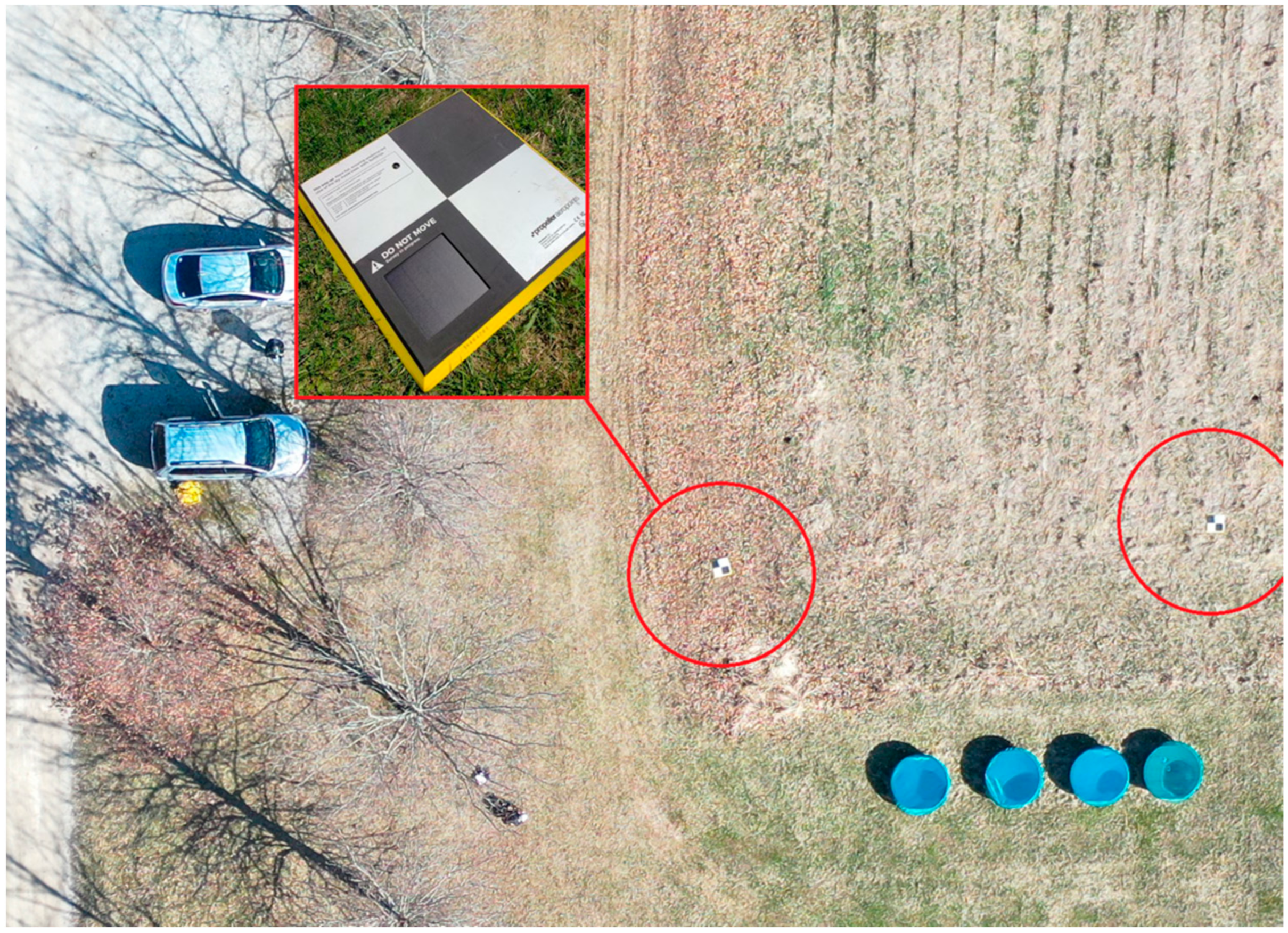
2.2.1. Precision Ground Control Options

Control can be achieved using several methods and technological approaches. If the user is dealing with a forestry application over a small area with a sparse canopy cover, such as harvested areas or tree planation operations, then the imagery can be adjusted using traditional ground control point markers [15]. These markers are often placed with an unobstructed view to the sky, and their precise location is recorded using a survey grade GPS (Figure 3). At odds with using this form of ground control is the reality that forestry is often performed in areas with a dense canopy and in rough terrain, which makes gathering spatial locations at centimeter-level precision difficult, if not impossible.
The increasing popularity and lower cost of Real-time kinematic (RTK) and post-processing kinematic (PPK) technology now present this technology as a viable solution for obtaining spatially representative datasets of forested areas, without the need for placing and recording ground-based GCPs [32]. PPK corrections are made after the flight has concluded and requires a rover log file containing coordinate locations and other pertinent time-of-collection information for each image captured during the flight. While both methods can provide a centimeter-level precision for image georeferencing [33,34], RTK requires a constant signal between the UAS and the base station during flight [35]. This presents an issue particular to forestry applications, where the dense canopy cover can deflect or disrupt this connection and return a spatially erroneous dataset [14]. The advantages of PPK are that the base station can be referenced long after the data collection mission using historical or continually calibrated data, so the potential for a loss of connection is eliminated.
Understanding the potential, limitations, and voids that UAS can encounter allows the user to gather on-demand, highly precise data for forest inventory research. Properly collected UAS data using PPK technology allow for data with a high spatial precision, without negating the inherent advantages of aerial surveys. PPK requires little additional time to prepare for use and post processes in comparison to GCPs [32]. Fewer steps not only create a more efficient workflow, but also one with less potential for error propagation. Furthermore, collecting the position of each image while also minimizing the chance of signal interference by surveying above the canopy and eliminating the need for a live radio link increases the reliability of this technology in densely forested areas. The products for the end-user forestry community hold enormous potential, when PPK-derived data are used in applied research and forest management situations [30]. PPK hardware, such as the Field-of-View Geosnap Pro, can be attached and integrated with a wide variety of after-market sensor payloads [35]. With so many sensor payloads currently on the market, it is important to factor in how the sensor will be used with the end goal in mind [31].

2.2.2. UAS Sensor Payload Types

The most common and inexpensive form of UAS sensor is that which captures imagery in the bandwidths of light visible to our own eye. This type of imagery is commonly referred to in the remote sensing community as RGB imagery for the combination of what we see in the Red, Green, and Blue portions of the visible spectrum [18]. Most sensors on the market today have pixel resolutions between 24 and 36 megapixels, which is more than ample for most UAS applications. Beyond these image pixel resolution considerations, choosing a sensor should also involve an understanding of the image sensor dimensions, along with the sensor field-of-view. The size of the image sensor on UAS platforms tends to be small, and this is why most UAS imagery is referred to as ‘Small Format Aerial Imagery’ [36]. The smaller sensor array means that distortion does occur in the imagery, with most of the distortion occurring near the edges. This distortion is often factored in when the imagery is processed in photogrammetric software, but understanding how sensor size can influence both distortion and the field-of-view (FOV) should be considered in the application. The sensor field-of-view relates not only to the sensor dimensions, but also to the type of lens being used. For a user to change the field-of-view, they must either increase the sensor size or change the lens of the sensor [18].
Most sensors used in mapping applications make use of a fixed focus lens type, which means that they cannot be used to zoom in and out and are used at a specific working distance, which, in the case of mapping with UAS, is the altitude above ground. The field-of-view of any lens gets larger the further away the UAS is from the target, so for UAS mapping, the wider the FOV, the higher the altitude. The focal length of a lens is often used to describe a lens and describes the length of the given lens very well. This information is important, but more important is the field-of-view of that lens. For example, one can purchase a common 35 mm lens and choose from a wide array of fields-of-view, where the field-of-view could range from nearly 100 degrees to as small as under 10 degrees. A wider FOV in forestry mapping operations means that the same area can be covered in a smaller amount of time than a sensor with a narrow FOV [19], which then translates into saving time and money. Therefore, it might be tempting for the user to look at purchasing a lens with the widest FOV possible, but it should be considered that a wide FOV comes at a trade off in terms of distortion moving toward the edge of the image and spectral contamination by capturing the side or bottom of leaves in image capture.
The good news about UAS sensors is that many commercial multi-rotor MS platforms, such as the DJI M600 or M210 multi-rotors, allow the user to easily swap out the sensor payload and even change the lens of the sensor, according to the application at hand [37]. These options should be left open, if the application may vary and does not always call for precise forest and vegetation mapping. The large payload capacity also allows for after-market custom sensor attachments, such as the field-of-view PPK Geosnap and Sony Alpha 6000 sensor to be used in addition to the gimbal mounted sensor payload. If precision is desired in terms of spectral reflectance from the canopy, then attention should be paid to a sensor that has a narrow FOV. Multispectral sensors, such as the MicaSense RedEdge and Altum sensors, have a narrow FOV of 47.8 and 49 degrees, respectively [37]. This narrow FOV allows the sensor to look straight down from above at the canopy, but it also translates into many narrower flight paths when mapping a given area. This means that the area being flown could be larger than the flight time of the multi-rotor platform, or in the case of using a fixed-wing, there could be a need to create a much larger mission area so the wide turn-radius of the aircraft allows for adherence to the especially narrow flight paths. The extra flight paths also mean that the number of images acquired in a mission goes up significantly, which means much more data to store and process. This needs to be considered, especially when dealing with multispectral sensors, where each image taken is actually 5–6 images, each representing its own spectral band. For example, a MicaSense Altum covering an area that took 100 images actually translates into the storage card holding an image for the 6 spectral bands, or 600 3.2 megabyte images. Considering that most mapping missions cover areas that require taking over 1000 images, the data storage and processing needs can quickly become an issue [30]. Fortunately, cloud-based processing and storage options are increasingly becoming cheaper and more readily available for those without existing budgets in place to set up the hardware for processing and storing such large amounts of data.

3. Establishing a UAS Program

When establishing a UAS program with the objective of aerial data collection, there are several steps that must be taken before flight operations can begin. Standard practices, regulations, and procedures must be created in order to ensure the effectiveness of the UAS program [38]. The creation of several standardized systems must be in place before the UAS program can operate efficiently. These systems include:
  • Crew Resource Management (CRM)
  • Safety Management Systems (SMS)
  • Standard Operating Procedure Documents (SOPs)
  • Fleet Management Systems
  • Standardized Scheduling and Communication Systems

3.1. Crew Resource Management (CRM)

Crew resource management refers to the effective use of all resources available to individual flight crews, which are used in order to create safe and efficient operations [39]. A single document can be created and accessed by all flight crews to properly distribute information regarding crew resource management. CRM is necessary, because it allows for standardized practices across all flight crews that are proven to create positive results [39]. A crew resource management document is created, so that all crew members are completely aware of their roles and how they should function as a team within the field. All content in this document must be clearly outlined for the flight crews to follow.

CRM Roles and Document Content

The responsibilities of each flight crew member should be clearly stated in order for operations to go smoothly and ensure no responsibilities are ignored. The recommended crew roles include the remote pilot in command, sensor operator, and visual observer [40]. The crew responsibilities within the preflight checklist must be clear for safe operations.
The remote pilot in command is the member of the flight crew, who is ultimately responsible for the operation and safety of the mission. The PIC’s responsibilities start with the preparation of the aircraft and crew for the mission. This begins with packing for the field, and the PIC will ensure that all equipment and documentation needed for the flight is at hand and that the flight crew is briefed on the mission. This equipment shall include all the components of the UAS platform to be used, the appropriate registration and documentation for the platform, and other documentation needed for the flight, such as the United States Federal Aviation Administration (FAA) exemptions, approval by local authorities to conduct the flight, etc. The crew shall be briefed on their assigned roles within the flight crew and the duties therein. The crew shall also be briefed on the details of the mission, including articles such as the location and directions to the mission site, means of transport, lodging (if applicable), etc. Once in the field, the PIC is responsible for overseeing the setup of the mission area by coordinating with other crew members to complete checklists and prepare for the launch of the mission. Once the aircraft is airborne, the PIC has the sole responsibility of the aircraft and shall always maintain communication with the Visual Observer (VO) during the flight. In summary, the PIC is in charge of the mission and is responsible for all aspects of the mission.
The Systems Officer (SO) will primarily be responsible for ensuring that data are properly collected during flights and the proper storage of data, once they are collected. This includes checking that the sensors aboard any aircraft are properly adjusted for the ensuing flight. The SO must be able to properly transfer data from the SD cards and return the SD cards to their correct storage location.
Visual Observer (VO): The first requirement for this role, as cited by U.S. FAA FAA part 107 regulations, is for the visual observer (VO) to be of sound physical and mental condition for their responsibilities [41]. A VO is also required to perform their work with unaided sight. The visual observer is also responsible for always maintaining sufficient communication with the pilot in command. During the flight, the VO should be ready to notify the pilot in command of any potential hazards that may present a risk of a crash. This should include keeping track of potential obstacles, warning of possible bird strikes, and keeping the ground station area free of anything that could interfere with the operations. The VO should also be able to provide status updates on the positioning and stability of the UAS while it is in flight. Visual observers must also have a deep knowledge of scenarios that may impact the flying conditions, including weather, ground hazards, and airborne hazards. It is also important for the VO to be wary of regulations outlined by CFR 14 part 107. Before the flight, the PIC and VO should communicate with everyone else in the flight crew regarding the roles and responsibilities, potential hazards, emergency procedures, contingency procedures, and operating conditions.
After each crew member becomes familiar with their individual role, it is recommended that they begin training each other and rotating roles. This is done so that all crew members can perform every task necessary in the operations and creates a failsafe for one crew member making a mistake. If one crew member is unable to attend a flight, the others should be able to perform his/her role. Knowing every step of the operations inside and out will only make them more efficient.
However, the crew role descriptions are not the only relevant portion of the CRM document. Again, CRM should provide flight crew members with everything they would need to operate within the field. This may include operational checklists for each role, an in-field vocabulary, in-field communication strategies, and emergency procedures.

3.2. Safety Management Systems (SMS) and General Risk Management

The use of Safety Management Systems is a program-wide approach to managing risk and ensuring the effectiveness of the risk management techniques that are implemented. Safety management systems include mandatory procedures and regulations created for risk management. This document should be constantly updated and growing in order to continuously track and improve upon safety issues. According to the FAA, there are four primary elements that compose a proper safety management system [42].
Safety Policy: The safety policy demonstrates the UAS management staff’s devotion to continually monitoring and improving the safety management systems. The safety policy defines the methods that will be implemented and the process through which these methods will be implemented. The safety policy also clearly illustrates the goals and objective outcomes of the safety management system. Documentation of these policies, methods for employees to report safety issues, and procedures for ensuring employee accountability are also important aspects regarding this component of safety management systems.
Safety Risk Management (SRM): Safety risk management is an official process within the safety management system that is used to recognize hazards, quantify risk, analyze risk, and then reduce and control that risk. Safety risk management can also be a process used to evaluate whether a mission’s risk level is acceptable or unacceptable. While there is risk in every mission, the safety risk management procedure is used to determine whether that risk is worth taking to complete the operation.
Safety Assurance (SA): Safety assurance is the component of SMS that is used to measure the effectiveness of the risk management practices being utilized. This includes defining actual metrics for gathering data to prove whether the created safety procedures work. Safety assurance is used to create a sense of compliance with the safety management systems and also the FAA regulations.
Safety promotion: This component of SMS is primarily concerned with training methods and company culture regarding risk management. Safety promotion activities within the SMS would entail a comprehensive SMS training plan, methods for improving safety culture, and activities for creating safety awareness among employees.
It is important to note how safety risk management and safety assurance impact one another. These two aspects of the safety management system are highly interconnected. The end result of safety risk management is either an acceptable or unacceptable risk. If the risk is accepted, the safety assurance component needs to be immediately implemented to evaluate and quantify how well this risk was handled.
The staff should also be well trained in how to make quick emergency decisions in common situations. These could include accidental take-off, a lost link, emergency landing, etc. Knowing how to deal with these situations before going into the field allows operators to rely on their training, instead of intuition/emotions, when these situations occur. Emergency training eliminates the need for rash decision making in these situations and instead allows the operator to focus on the methods that they were taught before arriving in the field [40].
Table 2 is an example of a common risk management planning chart that is commonly utilized in the aviation industry. This chart can be useful while engaging in evaluating the risk associated with specific missions. While the chart is obviously not a catch-all for risk management and does not guarantee that accidents will not occur, it is useful for standardizing risk evaluation and eliminating biased decision making. The operations falling within the green category can generally be considered very safe. The operations in the yellow category require more thought and discretion, and the operations in red are considered dangerous. If a mission falls within a red or yellow category, it is important to consider what can be done to mitigate this risk so that it can be reevaluated [42].

3.3. Standard Operating Procedure Documents (SOPs)

SOPs are documents that outline standardized methods for using certain equipment or completing specific tasks [43]. They allow best practices to be followed by personnel time and time again to create consistent results. Standard operating procedure documents are useful for creating uniform procedures among individuals and flight crews. SOPs can be used to illustrate how to properly use systems, equipment, sensors, and UAS platforms. The creation of SOPs is also integral for providing comprehensive guides on departmental responsibilities within a UAS program [44].

3.4. UAS Fleet Management

Proper management of UAS platforms and other necessary equipment is imperative for successful missions and quality data collection. Three prominent areas of fleet management include dispatch, equipment management, and maintenance. Dispatch is responsible for preparing aircraft for the field and properly receiving them after missions are completed. Equipment management is necessary for ensuring that items and platforms are properly stored and organized. Maintenance programs are implemented so UAS platforms can function in a proper and safe manner [39].

3.4.1. Dispatch and Equipment Organization

A UAS dispatch team is responsible for ensuring the preparation and organization of equipment for impending flight missions. The UAS dispatch organization is crucial for ensuring that equipment check-in and check-out are properly performed and documented. To track and monitor the use of equipment, proper check-in and check-out procedures must be introduced. The integration of a proper dispatch procedure will also ensure that all equipment is properly returned following a mission. This allows equipment that is lost or damaged to be recorded and monitored. Vehicle check-out and check-in forms can be used to request the use of UAS platforms for daily operations. Incident report forms can also be implemented into dispatch to record anomalies during missions that may affect the equipment. All forms and paperwork should be archived by the dispatch program to coordinate with maintenance, track UAS platform usage, and provide a proof of concept for the creation of dispatch roles. A standard operating procedure for dispatch should be created, and all operators should become incredibly familiar with that document [39].
All UAS fleet equipment should have a documented place to be stored. The documentation of these storage locations is recommended content for a dispatch SOP. Standardized locations allow for the quick location of equipment and decrease the likelihood of items being lost. Equipment labeling is also recommended to properly organize UAS fleet equipment. This can include labeling UAS platforms, UAS transmitters, batteries, and SD cards. Equipment labeling allows staff to be able to quickly identify specific equipment. It is also wise to create workflow documents for specific equipment. These workflows will allow staff to quickly learn the proper methods for using specific equipment [38]. For these workflow documents to be useful, they must be highly organized. It is important to date these documents and make it known when information needs to be updated. Equipment manuals should also be highly organized. The creation of a centralized location for storing data and workflow documents is recommended to maximize accessibility.

3.4.2. Maintenance

Proper maintenance practices are implemented so that UAS platforms and equipment operate properly within the field. Only staff with the proper knowledge and experience should be allowed to perform maintenance on UAS platforms. The maintenance staff should have access to documentation from UAS platform manufacturers and be familiar with practices recommended by these manufacturers. Maintenance personnel should also have access to the flight hour and battery cycle statistics to perform routine maintenance on the aircraft [45]. The UAS equipment maintenance should be intensely documented. Logbooks and maintenance records for all the equipment should be kept. This is important for tracking what steps have already been taken to repair and maintain the equipment. This also allows for accountability in the case of a mistake made by the maintenance personnel. Troubleshooting should also be documented in an incredibly detailed manner [46]. This allows for the isolation of the settings or factors that could be contributing to the issue at hand. It also allows for multiple maintenance personnel to work on the same problem by reading each other’s progress. This troubleshooting documentation also saves time by clearly illustrating which methods have already been exhausted. It is also useful for maintenance staff to keep a list of commonly needed replacement parts and where to purchase them. Parts such as propellers, which are frequently worn down, should be kept on hand and ordered in advance by maintenance staff before they are needed.

3.4.3. Standardized Communications and Scheduling

Missions should be scheduled using one source or online platform that all employees can access and view. Having multiple avenues for scheduling missions results in conflicts and miscommunication. A standardized method for scheduling reduces the likelihood of scheduling mistakes and increases the amount of clarity between flight crews. These accessible schedules not only allow operators to see when and where others are flying, but also what equipment is available to them. This is advantageous because it increases communication between flight crews and allows for these groups to plan and perform flight operations in a more cohesive manner. If missions are cancelled due to weather or other unforeseen circumstances, they should be rescheduled as soon as possible. Communication with other flight crews and management is necessary to properly correct this error.
Similar to scheduling, general out-of-field communication within the UAS program should be standardized. This means that all program communications should take place on one centralized application. The introduction of multiple communication methods can lead to missed information and a lack of clarity between flight crews and different departments [18]. Applications that allow for the creation of multiple communication channels are especially advantageous. Multiple communication channels can allow for the organization of information by department, which reduces the unnecessary information delivered to individuals, but also makes this information centralized and available to everyone if it is needed [47].

4. Mission Planning Considerations

4.1. Adhering to FAA Laws and Regulations

It is incredibly important to understand that most countries require a remote pilot license if UAS are to be flown for any sort of monetary compensation. Within the United States, this is the CFR 14 Part 107 Remote Pilots License. This license is acquired through passing a written test regarding safe operations, airspace regulations, aviation weather, and general aviation knowledge. Part 107 of the code of federal regulations outlines the regulations that govern professional drone operations. These regulations are designed to prevent the unsafe operation of UAS and prevent incidents, such as injury, crashes, and property damage (Table 3).

Airspace Authorization

Class Bravo, Charlie, Delta, and Echo airspaces all require ATC authorization to operate within them. LAANC is known as the Low-Altitude and Notification Capability that is compatible with many desktop and mobile mission planning apps. LAANC is usually able to provide rapid approval for airspace authorization from over 500 FAA facilities and over 700 airports. Some more complex operations that require the bending of part 107 rules may require a COA or certificate of waiver authorization from the FAA [41].

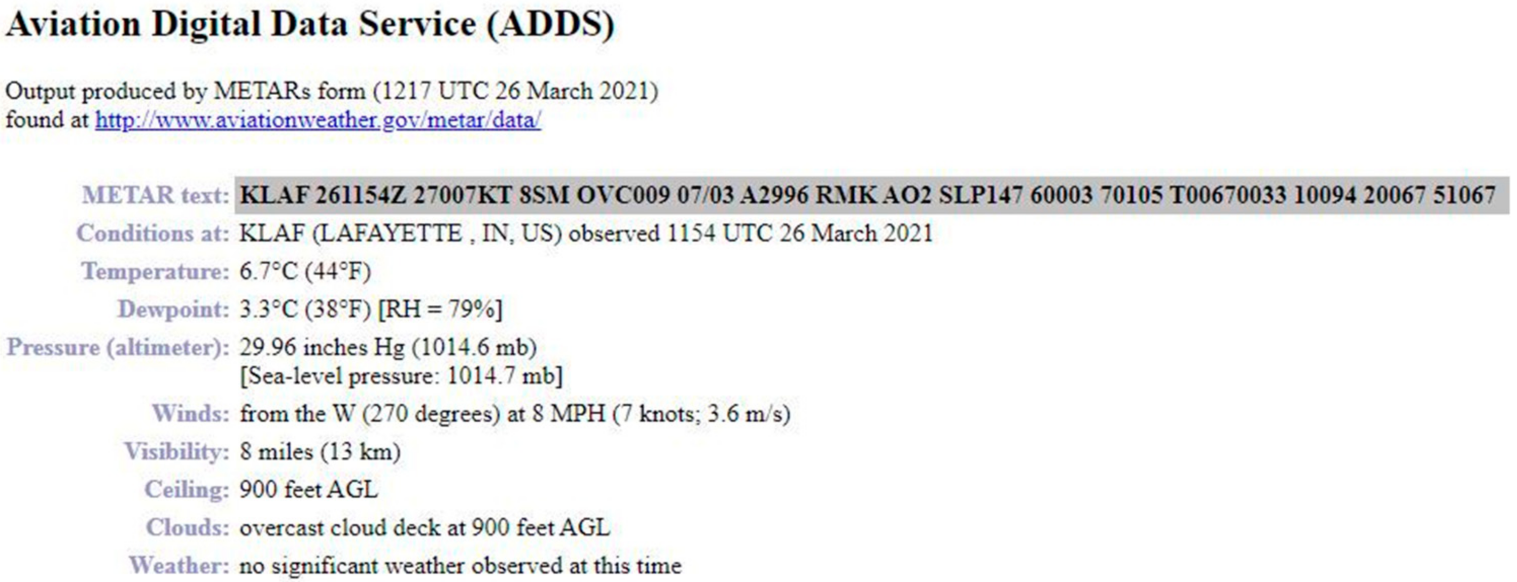
4.2. Weather Limitations

A list of weather limitations should be available and well known to all pilots. A laminated copy of these limitations should be kept within the hard case of the vehicle. This would include temperature, precipitation, and wind. The operation of a platform during these hazardous conditions could result in time wasted, damage to the aircraft, or a crash. Low and freezing temperatures are proven to drastically reduce or limit aircraft battery life [48]. Regarding precipitation, unless otherwise specified by the manufacturer, one should avoid getting UAS platforms wet at all costs. Moisture can cause the sensitive electronics within the UAS to malfunction or induce permanent damage. High winds have the potential to sway an aircraft from its flight path, cause crashes, negatively affect landings, reduce battery life, and reduce the data collection quality. Arriving to the field early in the morning for operations can assist in avoiding overly windy conditions. Aircraft manufacturers will also provide limitations regarding an aircraft’s ability to perform in the wind. An anemometer can be a useful piece of equipment for measuring wind speed in the field. Wind and weather conditions should be checked frequently 24 h in advance, as well as shortly before the mission. The METAR information should be recorded within the flight metadata for later reference (Figure 4). METAR is a French acronym that translates to “routine aviation routine weather report”. METARs are commonly used as a standard weather report for crewed flight applications. Besides a review of the METAR report, the UAS crew should look at the local weather conditions at the site being flown. Mobile device applications, such as Windy and Wunderground, are excellent for providing information on local wind speeds and directions.

4.3. Mission Planning Software

Similar to mission scheduling methods, mission planning software needs to be standardized. All flight crews should be assigned the same mission planning software. Allowing multiple flight crews to use different mission planning software is not efficient and will negatively impact the consistency of the data collected. Mission planning software should be carefully selected to best fit the needs of the project at hand. Mission planning and fleet management applications are especially useful for mission planning and operator evaluation. The software allows managers to create flight plans for their employees and enables the same manager to review these flights with useful statistics. The application automatically logs flight times, as well as other important data. This all-in-one approach to mission planning software can make planning operations much more organized. It may be beneficial to use an application with multiple capabilities, instead of using multiple applications for mission planning, flying, and record keeping.

4.4. Transportation

It is important to establish methods for transportation at least 24 h in advance, before a mission. If a flight crew is scrambling to find transportation methods before a mission, they may be unorganized and flustered before leaving and upon arriving to the field. Proper methods for acquiring transportation should be well known by all crew members. It may be wise to assign a specific crew member the responsibility of acquiring transportation in order to ensure that this task is completed. It is important to keep records of the mileage used for company vehicles for the purpose of financial documentation. Logbooks should be kept within each vehicle and updated at the end of every working day.

4.5. Area of Operations

It is important to make area maps and other important location information available to flight crews, so they can operate as safely and as efficiently as possible in the field. Area or terrain maps can be beneficial in helping the crew members navigate to and from the jobsite effectively. Differences in terrain and other abnormalities also have the potential to negatively affect the quality of UAS data, so all staff should be extremely familiar with the land they are working on.
Airspace maps are necessary in order to inform operators of any regulations or notices to airmen for the airspace they are operating under. Depending on the airspace, an operator may have to apply for a certificate of waiver authorization or LAANC authorization in order to operate at high altitudes or in restricted airspace [41].

Common Hazard Information

Information about potential hazards or distractions within the field should be kept and regularly updated for the purpose of mission planning.
Common manned aviation flight paths: When a manned aircraft approaches the flight area, it can sometimes cause panic for operators. These emotions come from several unknown factors, including the aircraft’s altitude and the direction from which the aircraft is coming from. Keeping records of common flight paths over the area give operators more information to confidently handle the approach of a manned aircraft. For example, if a visual observer hears a manned aircraft approaching but cannot determine its direction, they will have an idea of where to look. If the manned aircraft usually approaches the flight area from the southeast, for example, this specific direction could be checked quickly and frequently. The ability to estimate flight altitudes is also important, because low-flying manned aircraft can sometimes result in the temporary grounding of the UAS platform for safety reasons.
Bird population information: A bird strike on an unmanned aircraft has the potential to cause a crash, cause permanent airframe damage, or create a safety hazard for personnel on the ground. Bird population information can provide comprehensive details useful for reducing the likelihood of a bird strike occurring. Important questions may be:
a.
Are there large flocks of birds frequently inhabiting this area?
b.
Are there large potentially aggressive birds of prey in the area?
c.
Will migration patterns affect this flight?
d.
Have there been issues with birds in this area before?
Tree population height information: The maximum tree height is useful for determining the flight altitude. According to CFR 14 Part 107, a UAS operator is able to fly above the 400 ft AGL altitude limit if avoiding obstacles. There should be a substantial amount of clearance between the aircraft and the tallest outliers within the flight path.
Objects/areas that commonly create magnetic field interference: Large metal objects, powerlines, and large concrete slabs are some examples of some common fixtures that can create magnetic interference issues. This interference can cause UAS flight controllers to malfunction, which can result in disaster [48]. The locations of objects thought to be causing interference should be documented. There are tools that can be used in the field, including spectrometers and mobile apps, in order to detect and measure interference [31].
Wildlife and animal hazards: Encounters with any sort of wild animal can be incredibly distracting for operators during the flight, especially if this animal is aggressive. Plans and training should be put in place so that operators are mentally prepared for these situations beforehand. Keeping a record of the animals within the area is also useful for keeping UAS pilots informed about their surroundings.
Obstacle Awareness Information: It is useful to keep a list of potential flight hazard locations, because this allows operators to enter the field fully prepared to deal with these obstacles. When the locations of these obstacles are known and documented, it is easier for flight crews to adapt their flight plans and manage risk effectively. The standardization of how to deal with these obstacles is also useful, because in the event that flight plans are effectively altered for a specific obstacle, they can be used again later, instead of having to repeatedly solve the same issue.

5. Field Operations

5.1. Data Collection Strategies

When conducting a mission, it is important to identify environmental factors that could affect the data quality and to understand how to adjust data collection methods accordingly. The time of day, weather conditions, and terrain are all prominent factors to be aware of, and often the cornerstone of these considerations is lighting. Many sensors come equipped with an “auto” mode, which calculates the optimal settings for the given environment. However, these auto settings may sometimes compromise the image quality, which is why it is important to understand the implications of lighting and the sensors’ settings.
Regarding RGB imagery, the three main elements for achieving the proper lighting or exposure are: ISO, shutter speed, and aperture (Table 4). ISO is the sensors’ sensitivity level of light. Lower ISOs require more light but typically produce sharper images. The acceptable ISO is usually in the range of 100–800, but it depends on the quality of the sensor and the data quality requirements. The shutter speed refers to the duration of time that the sensor is exposed to light. High shutter speeds help capture the subject clearly while the UAS is in motion but also require more lighting. Aperture is the size of the opening in the lens that allows light in. Lower aperture numbers allow more light but reduce the depth of field or how sharp the foreground of an image is, compared to the background. Each of these settings are important to consider in collecting sharp, well-exposed images.
If the settings in auto mode are not producing the desired image quality, manual or partially manual modes, such as shutter priority, should be considered. These modes constrain some settings to a fixed value, while others can be automatically calculated while the flight is in progress. In general, it is important to understand the features and limitations of the sensors and what they imply for a given environment. Understanding how to tune the settings to the needs of the mission is imperative in obtaining high-quality data. Finally, understanding how the environment and these settings can affect the data quality is a continuous learning process, which is why it is also important to keep notes on the sensor settings and environmental conditions for each dataset.

5.2. Field Notes and Documentation

Proper documentation on field activities and events is extremely useful for the creation of a successful UAS program. Field notes and reports should create a comprehensive narrative of the daily operations, which can be presented to management. Field notes and reports also justify the necessity of certain tasks and behaviors within the field to those uninformed of UAS activities. This documentation can also be useful for training materials and allows the flight crews to continuously build upon previous operations. In the event of an accident, this record keeping is also useful for determining the cause and creating methods for what can be done differently in the future. Field notes can include but are not limited to metadata, notes on the surroundings, notes on the terrain, details about the flight crew, details about the equipment, the weather conditions, the tasks completed, the challenges encountered, and details on the mistakes that may have occurred.

5.3. Equipment Checkpoints

Equipment checkpoints are an unglamorous, and often overlooked, aspect of a fail-safe UAS operation. These checkpoints are designed to prevent the loss of equipment and/or to check for damaged equipment between flights. All equipment should be inspected at each of these points. The idea behind inspecting in between flights is that sometimes vibration or movement in the flight can affect the equipment, leading it to malfunction [49]. This can result in a crash or the loss of data collection. The equipment can also be damaged and lost during transportation and packing/unpacking. Again, this can result in a loss of data or damage to the aircraft.
  • Before leaving dispatch
  • Upon arrival to the operations site
  • Between flights
  • Before packing/leaving site
  • Upon returning to the dispatch area

5.4. Pre-Flight Checklists

One standardized pre- and post-flight checklist should be created for every individual UAS platform and associated sensor payload. The use of one pre-flight checklist allows for the same tasks to be followed by each flight crew. This standardization creates uniformity among the tasks performed by each individual flight crew [39]. Crews should always be looking for ways to improve upon the pre-flight checklist for respective vehicles. Adding steps that may be overlooked can result in more efficient operations. Revisions to the pre-flight checklist should be made explicitly available to all flight crews. It is convenient to keep a record of what tasks are added to the checklist and for what reason to justify these changes. While old pre-flight checklist versions should be kept for the purpose of documentation, it should be made obvious which checklist is the most current.
It is recommended that crew members challenge one and other to double check that certain tasks and responsibilities are completed. This should be done in a friendly and non-personal way. This method of checking and challenging crew members is an extra failsafe that can be implemented to improve the likelihood that a pre-flight checklist is followed perfectly [49].

5.5. In-Field Communications

During operations, information needs to be communicated clearly and quickly. For information to be clearly understood by all flight crew members, standardized terms must be created (Table 5). Standard phrases should be created for: aircraft orientation, specific checklist steps, aircraft status updates, directions, and emergencies.
This is not a comprehensive list of all communication phrases that require standardization. When a crew resource management plan is created, a list of standardized phrases must be created. This vocabulary should be continually updated. New flight crew members should be required to learn this vocabulary as part of their training. Announcing the actions completed during the pre-flight stage allows all flight crew members to be completely informed regarding which steps of the checklist have been completed.

6. Conclusions

Unmanned Aerial Systems are no longer a novel concept and present themselves as a valid remote sensing tool in a wide variety of forestry applications. These platforms can gather imagery over forested areas at spatial and temporal resolutions never before imagined. That said, the role of UAS in any forest operation should always be considered as one tool among many in the forester’s toolbox for engaging in forest management practices. While many technological limitations have been overcome in recent years, such as improved batteries for longer flight times and PPK GPS for a high precision, legal restrictions remain, along with the need to treat UAS operations in the same manner that one would treat data collection with a manned aircraft. Careful consideration should be given to the development of a UAS fleet regarding the number of and type of aircraft, understanding the differences between fixed-wing and multi-rotor aircraft. Equal consideration should be given to the sensor payload, as this device is what is ultimately being used to lower the overhead costs and improve efficiencies. Once a UAS fleet has been developed, it is especially important to have a trained crew operate the aircraft and to have a series of protocols and policies in place to ensure that the data are collected in a safe and effective manner. Finally, by adhering to a series of data collection strategies, one can ensure that the quality of the data matches the needs of the operation. The material presented in this technical report represents years of lessons learned through trial and error in the field, yet these approaches are constantly being refined. The best practices mentioned here will likely change as policies change, restrictions are lifted, and the technology continues to improve.

Author Contributions

Conceptualizationn C.C. and J.H.; Original draft preparation, C.C., J.G. and J.H.; Literature Review and Citations, A.C. and Z.M.; Review and Editing, J.H.; Figures and Tables, C.C. All authors have read and agreed to the published version of the manuscript.

Funding

No internal or external funds supported this research. The research was conducted as part of an undergraduate research endeavor.

Data Availability Statement

No data analysis went into this systemic review paper.

Conflicts of Interest

The authors declare no conflict of interest. No external or internal funding had a role in the writing of the manuscript.

References

  1. Frayer, W.E.; Furnival, G.M. Forest Survey Sampling Designs: A History. J. For. 1999, 97, 4–10. [Google Scholar] [CrossRef]
  2. Mckendry, J.; Eastman, R. Applications of GIS in Forestry: A Review. 2021. Available online: www.nrac.wvu.edu/classes/for326/GISInForestryReviewPaper.pdf (accessed on 31 March 2021).
  3. The History of geographic information systems: Perspectives from the pioneers. Choice Rev. Online 1998, 36, 36–2183. [CrossRef]
  4. Manfreda, S.; McCabe, M.F.; Miller, P.E.; Lucas, R.; Pajuelo Madrigal, V.; Mallinis, G.; Ben-Dor, E.; Helman, D.; Estes, L.; Ciraolo, G.; et al. On the Use of Unmanned Aerial Systems for Environmental Monitoring. Remote Sens. 2018, 10, 641. [Google Scholar] [CrossRef] [Green Version]
  5. Anderson, K.; Gaston, K.J. Lightweight unmanned aerial vehicles will revolutionize spatial ecology. Front. Ecol. Environ. 2013, 11, 138–146. [Google Scholar] [CrossRef] [Green Version]
  6. Watts, A.C.; Ambrosia, V.G.; Hinkley, E.A. Unmanned Aircraft Systems in Remote Sensing and Scientific Research: Classification and Considerations of Use. Remote Sens. 2012, 4, 1671–1692. [Google Scholar] [CrossRef] [Green Version]
  7. Homainejad, N.; Rizos, C. Application of Multiple Categories of Unmanned Aircraft Systems (UAS) in Different Airspaces for Bushfire Monitoring and Response. ISPRS Int. Arch. Photogramm. Remote Sens. Spat. Inf. Sci. 2015, XL-1/W4, 55–60. [Google Scholar] [CrossRef] [Green Version]
  8. Fraser, B.T.; Congalton, R.G. Issues in Unmanned Aerial Systems (UAS) Data Collection of Complex Forest Environments. Remote Sens. 2018, 10, 908. [Google Scholar] [CrossRef] [Green Version]
  9. Fernández-Guisuraga, J.M.; Sanz-Ablanedo, E.; Suárez-Seoane, S.; Calvo, L. Using Unmanned Aerial Vehicles in Postfire Vegetation Survey Campaigns through Large and Heterogeneous Areas: Opportunities and Challenges. Sensors 2018, 18, 586. [Google Scholar] [CrossRef] [PubMed] [Green Version]
  10. Gillan, J.K.; Karl, J.W.; Elaksher, A.; Duniway, M.C. Fine-Resolution Repeat Topographic Surveying of Dryland Landscapes Using UAS-Based Structure-from-Motion Photogrammetry: Assessing Accuracy and Precision against Traditional Ground-Based Erosion Measurements. Remote Sens. 2017, 9, 437. [Google Scholar] [CrossRef] [Green Version]
  11. Gini, R.; Passoni, D.; Pinto, L.; Sona, G. Use of Unmanned Aerial Systems for multispectral survey and tree classification: A test in a park area of northern Italy. Eur. J. Remote Sens. 2014, 47, 251–269. [Google Scholar] [CrossRef]
  12. Gini, R.; Sona, G.; Ronchetti, G.; Passoni, D.; Pinto, L. Improving Tree Species Classification Using UAS Multispectral Images and Texture Measures. ISPRS Int. J. Geo-Inf. 2018, 7, 315. [Google Scholar] [CrossRef] [Green Version]
  13. Guerra-Hernández, J.; González-Ferreiro, E.; Monleón, V.J.; Faias, S.P.; Tomé, M.; Díaz-Varela, R.A. Use of Multi-Temporal UAV-Derived Imagery for Estimating Individual Tree Growth in Pinus pinea Stands. Forests 2017, 8, 300. [Google Scholar] [CrossRef]
  14. Tomaštík, J.; Mokroš, M.; Saloň, Š.; Chudý, F.; Tunák, D. Accuracy of Photogrammetric UAV-Based Point Clouds under Conditions of Partially-Open Forest Canopy. Forests 2017, 8, 151. [Google Scholar] [CrossRef] [Green Version]
  15. Tomaštík, J.; Mokroš, M.; Surový, P.; Grznárová, A.; Merganič, J. UAV RTK/PPK Method—An Optimal Solution for Mapping Inaccessible Forested Areas? Remote Sens. 2019, 11, 721. [Google Scholar] [CrossRef] [Green Version]
  16. Harwin, S.; Lucieer, A. Assessing the Accuracy of Georeferenced Point Clouds Produced via Multi-View Stereopsis from Unmanned Aerial Vehicle (UAV) Imagery. Remote Sens. 2012, 4, 1573–1599. [Google Scholar] [CrossRef] [Green Version]
  17. Zhang, H.; Aldana Jague, E.; Clapuyt, F.; Wilken, F.; Vanacker, V.; Oost, K. Evaluating the Potential of PPK Direct Georeferencing for UAV-SfM Photogrammetry and Precise Topographic Mapping. Earth Surf. Dyn. Discuss. 2019, 7, 807–827. [Google Scholar] [CrossRef] [Green Version]
  18. Gupta, S.G.; Ghonge, M.; Jawandhiya, P.M. Review of Unmanned Aircraft System (UAS). SSRN Electron. J. 2013. [Google Scholar] [CrossRef]
  19. Pádua, L.; Vanko, J.; Hruška, J.; Adão, T.; Sousa, J.J.; Peres, E.; Morais, R. UAS, sensors, and data processing in agroforestry: A review towards practical applications. Int. J. Remote Sens. 2017, 38, 2349–2391. [Google Scholar] [CrossRef]
  20. Myers, D.; Ross, C.M.; Liu, B. A review of unmanned aircraft system (UAS) applications for agriculture. In Proceedings of the 2015 ASABE Annual International Meeting, New Orleans, LA, USA, 26–29 July 2015; p. 1. [Google Scholar]
  21. Hassler, S.C.; Baysal-Gurel, F. Unmanned Aircraft System (UAS) Technology and Applications in Agriculture. Agronomy 2019, 9, 618. [Google Scholar] [CrossRef] [Green Version]
  22. Boon, M.A.; Drijfhout, A.P.; Tesfamichael, S. Comparison of a Fixed-Wing and Multi-Rotor UAV for Environmental Mapping Applications: A Case Study. ISPRS Int. Arch. Photogramm. Remote Sens. Spat. Inf. Sci. 2017, XLII-2/W6, 47–54. [Google Scholar] [CrossRef] [Green Version]
  23. Tahar, K.N.; Ahmad, A. An evaluation on fixed wing and multi-rotor UAV images using photogrammetric image processing. Int. J. Comput. Inf. Eng. 2013, 7, 48–52. [Google Scholar]
  24. González-Rocha, J.; De Wekker, S.F.J.; Ross, S.D.; Woolsey, C.A. Wind Profiling in the Lower Atmosphere from Wind-Induced Perturbations to Multirotor UAS. Sensors 2020, 20, 1341. [Google Scholar] [CrossRef] [PubMed] [Green Version]
  25. DJI. Matrice 600 Pro Product Information. Available online: dji.com/matrice600-pro/info (accessed on 31 March 2021).
  26. Aerospace Ltd. Bramor ppX. Available online: https://www.c-astral.com/en/unmanned-systems/bramor-ppx (accessed on 21 March 2021).
  27. Arterburn, D.R.; Duling, C.T.; Goli, N.R. Ground Collision Severity Standards for UAS Operating in the National Airspace System (NAS). In Proceedings of the 17th AIAA Aviation Technology, Integration, and Operations Conference, Denver, CO, USA, 5–9 June 2017; p. 3778. [Google Scholar]
  28. Ristorto, G.; Mazzetto, F.; Guglieri, G.; Quagliotti, F.G.R. Monitoring performances and cost estimation of multirotor Unmanned Aerial Systems in precision farming. In Proceedings of the 2015 International Conference on Unmanned Aircraft Systems (ICUAS), Denver, CO, USA, 9–12 June 2015; pp. 502–509. [Google Scholar]
  29. Ozdemir, U.; Aktas, Y.O.; Vuruskan, A.; Dereli, Y.; Tarhan, A.F.; Demirbag, K.; Erdem, A.; Kalaycioglu, G.D.; Ozkol, I.; Inalhan, G. Design of a Commercial Hybrid VTOL UAV System. J. Intell. Robot. Syst. 2014, 74, 371–393. [Google Scholar] [CrossRef]
  30. Tang, L.; Shao, G. Drone remote sensing for forestry research and practices. J. For. Res. 2015, 26, 791–797. [Google Scholar] [CrossRef]
  31. Goodbody, T.R.; Coops, N.C.; Marshall, P.L.; Tompalski, P.; Crawford, P. Unmanned aerial systems for precision forest inventory purposes: A review and case study. For. Chron. 2017, 93, 71–81. [Google Scholar] [CrossRef] [Green Version]
  32. Miller, Z.M.; Hupy, D.J.P.; Chandrasekaran, A.; Shao, G.; Fei, S. Application of post-processing kinematic methods with UAS remote sensing in forest ecosystems. J. For. 2021, fvab021. [Google Scholar] [CrossRef]
  33. Stöcker, C.; Nex, F.; Koeva, M.; Gerke, M. Quality Assessment of Combined IMU/GNSS Data for Direct Georeferencing in the Context of UAV-Based Mapping. ISPRS Int. Arch. Photogramm. Remote Sens. Spat. Inf. Sci. 2017, 42, 355–361. [Google Scholar] [CrossRef] [Green Version]
  34. Wiącek, P.; Pyka, K. The Test Field for UAV Accuracy Assessments. ISPRS Int. Arch. Photogramm. Remote Sens. Spat. Inf. Sci. 2019, 4212, 67–73. [Google Scholar] [CrossRef] [Green Version]
  35. Bakuła, M.; Oszczak, S.; Pelc-Mieczkowska, R. Performance of RTK Positioning in Forest Conditions: Case Study. J. Surv. Eng. 2009, 135, 125–130. [Google Scholar] [CrossRef]
  36. Aber, J.S.; Marzolff, I.; Ries, J.B. Chapter 1: Introduction to Small-Format Aerial Photography. In Small-Format Aerial Photography and UAS Imagery; Elsevier: New York, NY, USA, 2010; pp. 1–13. [Google Scholar] [CrossRef]
  37. DJI. Zenmuse X7–Product Information: Specs. 2021. Available online: https://www.dji.com/cn/zenmuse-x7/info (accessed on 21 March 2021).
  38. Lercel, D.J.; Hupy, J.P. Developing a Competency Learning Model for Students of Unmanned Aerial Systems. Coll. Aviat. Rev. Int. 2020, 38, 38. [Google Scholar] [CrossRef]
  39. Kanki, B.G.; Anca, J.; Chidester, T.R. Crew Resource Management; Academic Press: Cambridge, MA, USA, 2019. [Google Scholar]
  40. Weldon, W.T.; Hupy, J. Investigating Methods for Integrating Unmanned Aerial Systems in Search and Rescue Operations. Drones 2020, 4, 38. [Google Scholar] [CrossRef]
  41. FAA. 14 CFR–Part 107: Small Unmanned Aerial Systems. Available online: https://www.ecfr.gov/cgi-bin/text-idx?SID=795f3720e106147f41212aef340f0d11&mc=true&node=pt14.2.107&rgn=div5 (accessed on 8 April 2021).
  42. FAA. AC 150/5200-37—Introduction to Safety Management Systems (SMS) for Airport Operators. Available online: https://www.faa.gov/documentLibrary/media/Advisory_Circular/AC_150_5200-37.pdf (accessed on 8 April 2021).
  43. FAA. Standard Operating Procedures (SOP). Available online: https://www.faa.gov/airports/resources/sops/ (accessed on 8 April 2021).
  44. Fang, S.X.; O’Young, S.; Rolland, L. Development of Small UAS Beyond-Visual-Line-of-Sight (BVLOS) Flight Operations: System Requirements and Procedures. Drones 2018, 2, 13. [Google Scholar] [CrossRef] [Green Version]
  45. Di Gironimo, G.; Di Martino, C.; Lanzotti, A.; Marzano, A.; Russo, G. Improving MTM-UAS to predetermine automotive maintenance times. Int. J. Interact. Des. Manuf. (IJIDeM) 2012, 6, 265–273. [Google Scholar] [CrossRef] [Green Version]
  46. Hu, J.; Fan, T.; Han, L.; Xu, W.; Wu, J. Research on UAS Safety and Security using System Thinking. In Proceedings of the 2020 3rd International Conference on Unmanned Systems (ICUS), Harbin, China, 27–28 November 2020; pp. 178–183. [Google Scholar]
  47. Wargo, C.A.; Church, G.C.; Glaneueski, J.; Strout, M. Unmanned Aircraft Systems (UAS) research and future analysis. In Proceedings of the 2014 IEEE Aerospace Conference, Big Sky, MT, USA, 1–8 March 2014; pp. 1–16. [Google Scholar]
  48. Ayele, Y.Z.; Ashraf, B. Preliminary Hazard Analysis for UAV-Assisted Bridge Inspection. Urban Transport XXVI 2020, 200, 171. [Google Scholar] [CrossRef]
  49. FAA. Safety Management Systems (SMS). Available online: https://www.faa.gov/about/initiatives/sms/ (accessed on 8 April 2021).
Figure 1. The M600 on a landing pad.
Forests 12 00957 g001
Figure 2. C-Astral Bramor Fixed-Wing Launching Mechanism.
Forests 12 00957 g002
Figure 3. Aeropoint ground control point (GCP) markers (Outlined in Red) being utilized in a UAS data collection mission.
Forests 12 00957 g003
Figure 4. Example METAR Aviation Weather Report from KLAF.
Forests 12 00957 g004
Table 1. Comparative assessment of the multi-rotor and fixed-wing aircraft platforms.
Multi-Rotor UAS AdvantagesFixed-Wing UAS Advantages
Simple control schemeLonger and faster flights
Ability to hover in placeSafer flights at high altitudes
Vertical takeoff and landingHigher resistance to adverse weather
Affordable and accessibleCan be easier to maintain
Multi-Rotor UAS DisadvantagesFixed-Wing UAS Disadvantages
Shorter flight timeComplex takeoff and landing operations
Higher battery demandsRequire more space to operate safely
Rotor blades are dangerousComplex mission planning
Multi-Rotors Are Beneficial forFixed-Wing UAS Are Beneficial for
Smaller flight areasLarger flight areas, high-altitude missions
Less experienced flight crewsExperienced flight crews
Smaller flight crewsLarger flight crews
Tight takeoff and landing operationsSpacious takeoff and landing locations
Table 2. Risk management planning chart.
Risk Probability RatingRisk Severity Rating
A CatastrophicB HazardousC MajorD MinorE Negligible
5 Frequent5A5B5C5D5E
4 Occasional4A4B4C4D4E
3 Remote3A3B3C3D3E
2 Improbable2A2B2C2D2E
1 Extremely Improbable1A1B1C1D1E
Table 3. Common Part 107 Laws.
Common Part 107 Regulations
Strict avoidance of manned aircraft
Refraining from operating UAS in a generally negligent manner
Refraining from operating beyond the visual line of sight (VLOS)
Refraining from flying over persons not involved in the flight operation
Minimum weather visibility: 3 statute miles
Maximum flight altitude: 400 ft above ground level (AGL)
UAS must weigh less than 55 lbs.
UAS must be registered with the FAA and visibly labeled with the registration number
Cannot fly before sunset and after sunrise
Maximum flight is speed is 100 mph
Table 4. Ambient Light vs. Camera Settings.
Shutter SpeedISOAperture
Low LightLow speed
(High shutter interval number)
High sensitivity
(High ISO number)
More open
(Low f/stop number)
High LightHigh speed
(Low shutter interval number)
Low sensitivity
(Low ISO number)
Less open
(High f/stop number)
Table 5. Examples of communications that require standards.
Options for Positions and DirectionsAircraft Conditions
Degrees: 0, 90, 180, 270, etc.Line of sight status
Clock Positions, 3 O’clock, 6 O’clock, etc.GPS/Sensor Connections
Cardinal Directions: North, South, etc.Aircraft armed, taking off, landing
Publisher’s Note: MDPI stays neutral with regard to jurisdictional claims in published maps and institutional affiliations.

