
Effect of Multi-Element Microalloying on the Structure and Properties of High Chromium Cast Iron
Abstract
:
1. Introduction
2. Materials and Methods
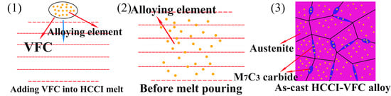
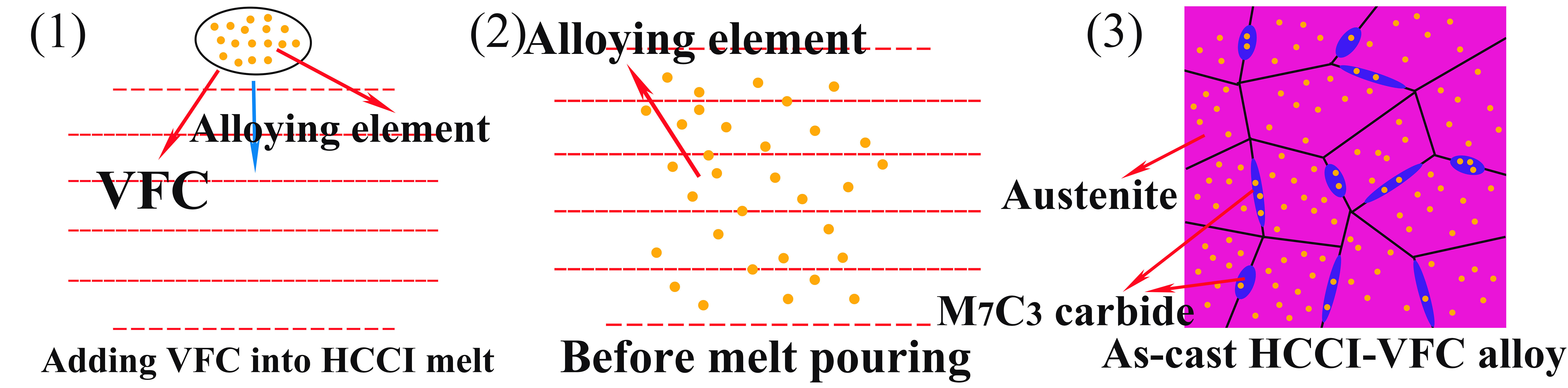
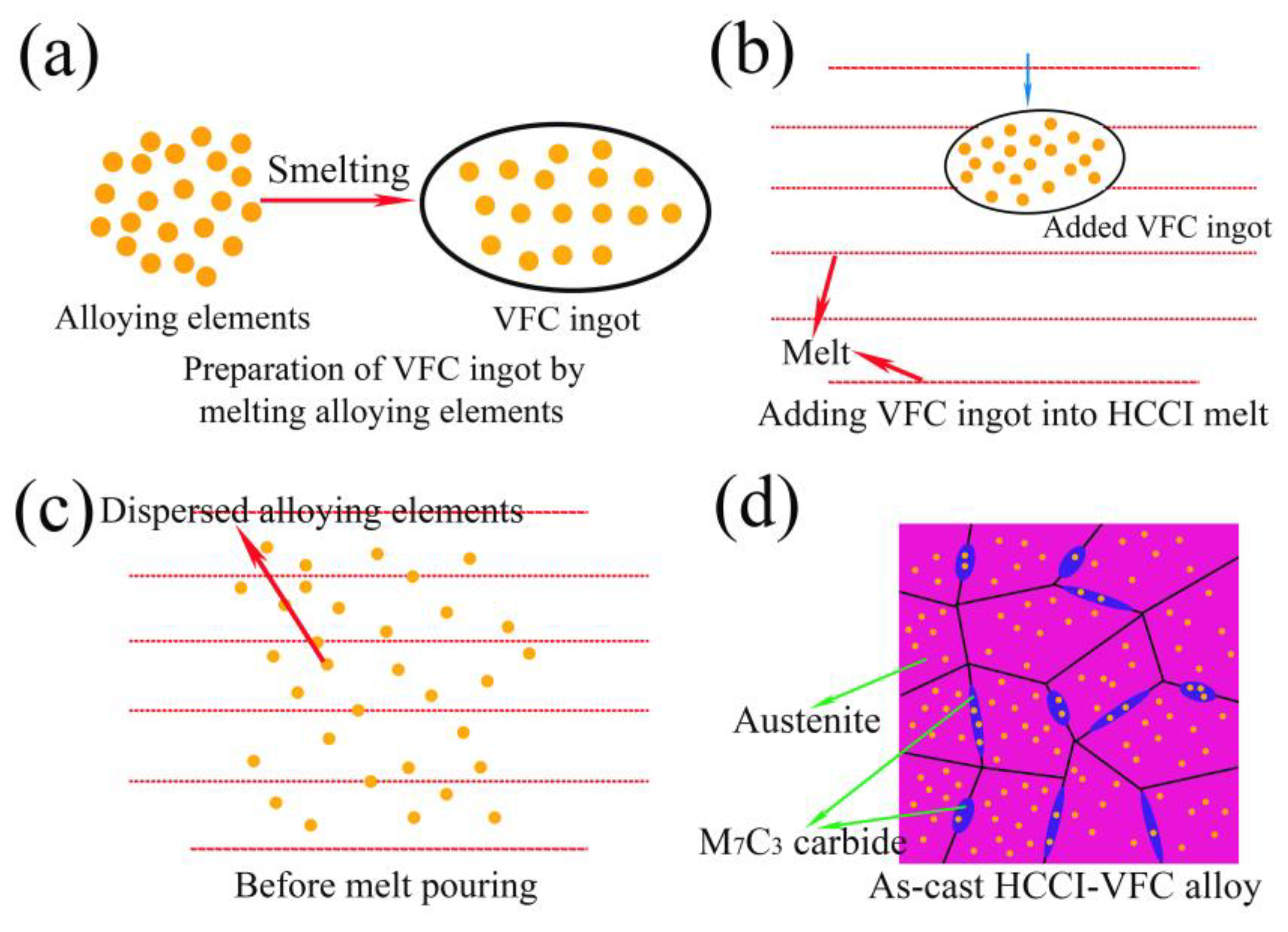
2.1. Alloy Preparation
2.2. Structural and Mechanical Property Test
3. Results and Discussion
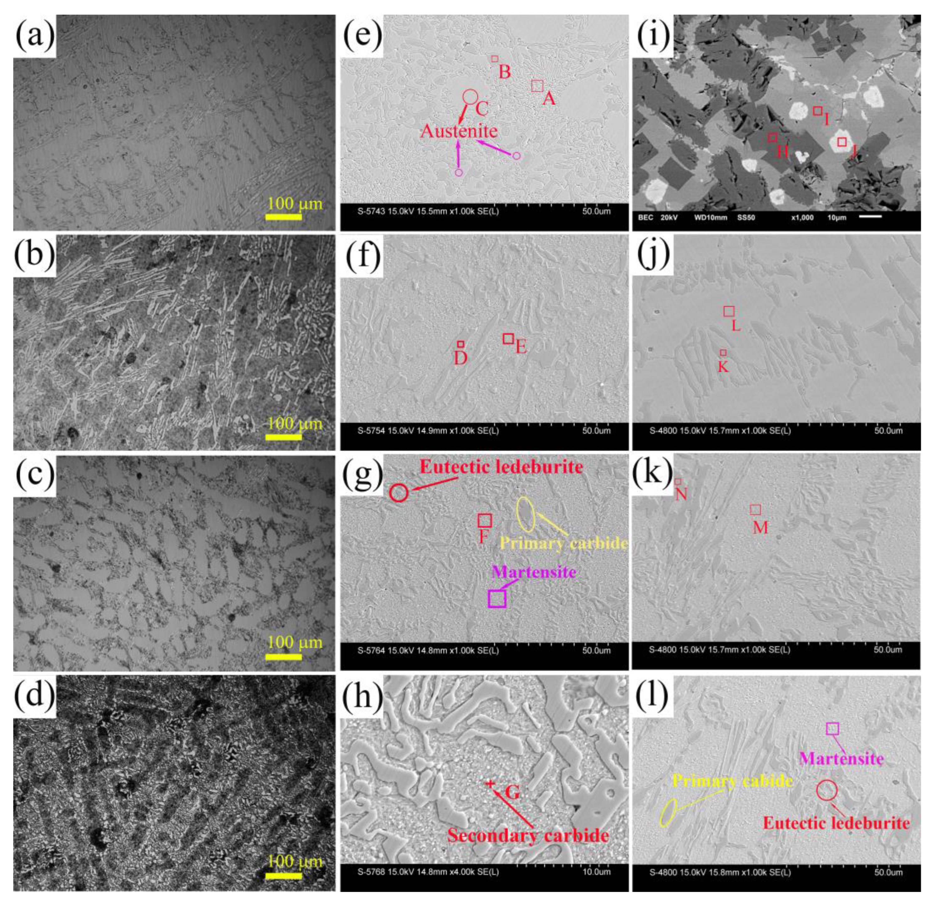
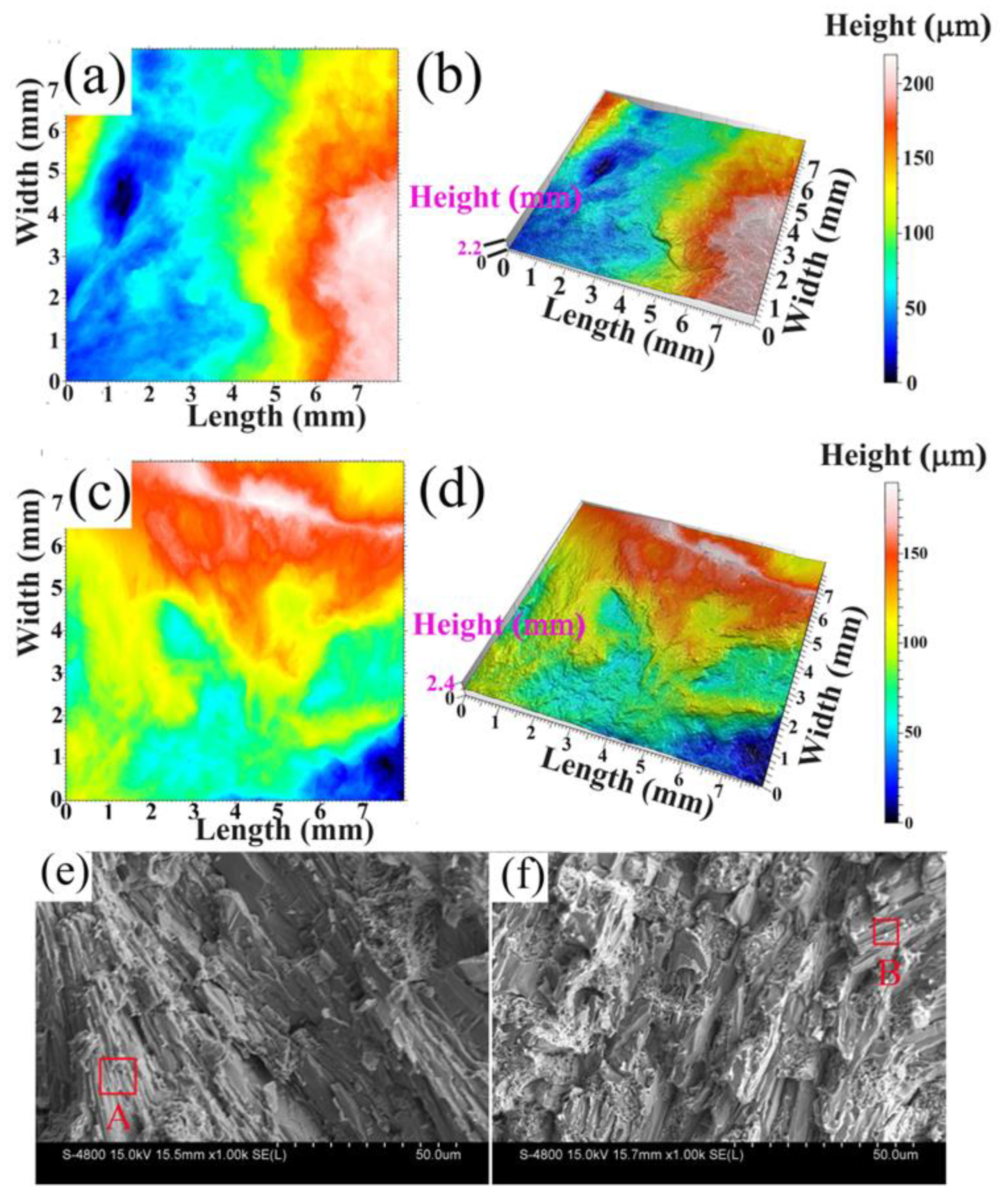
3.1. Microstructure
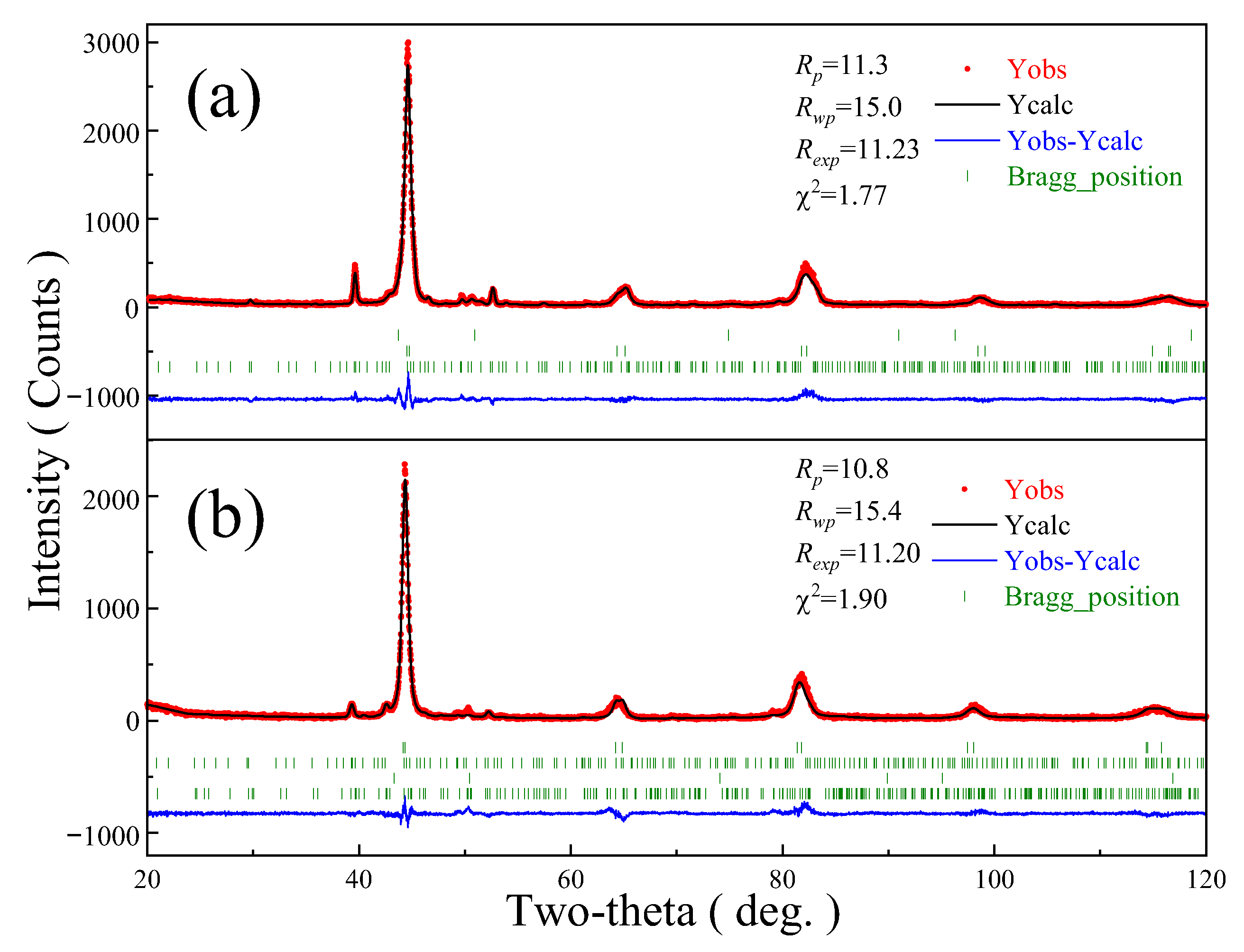
3.2. Phase Transformation
3.3. Alloying Effect on Mechanical Properties
3.3.1. Hardness
3.3.2. Toughness
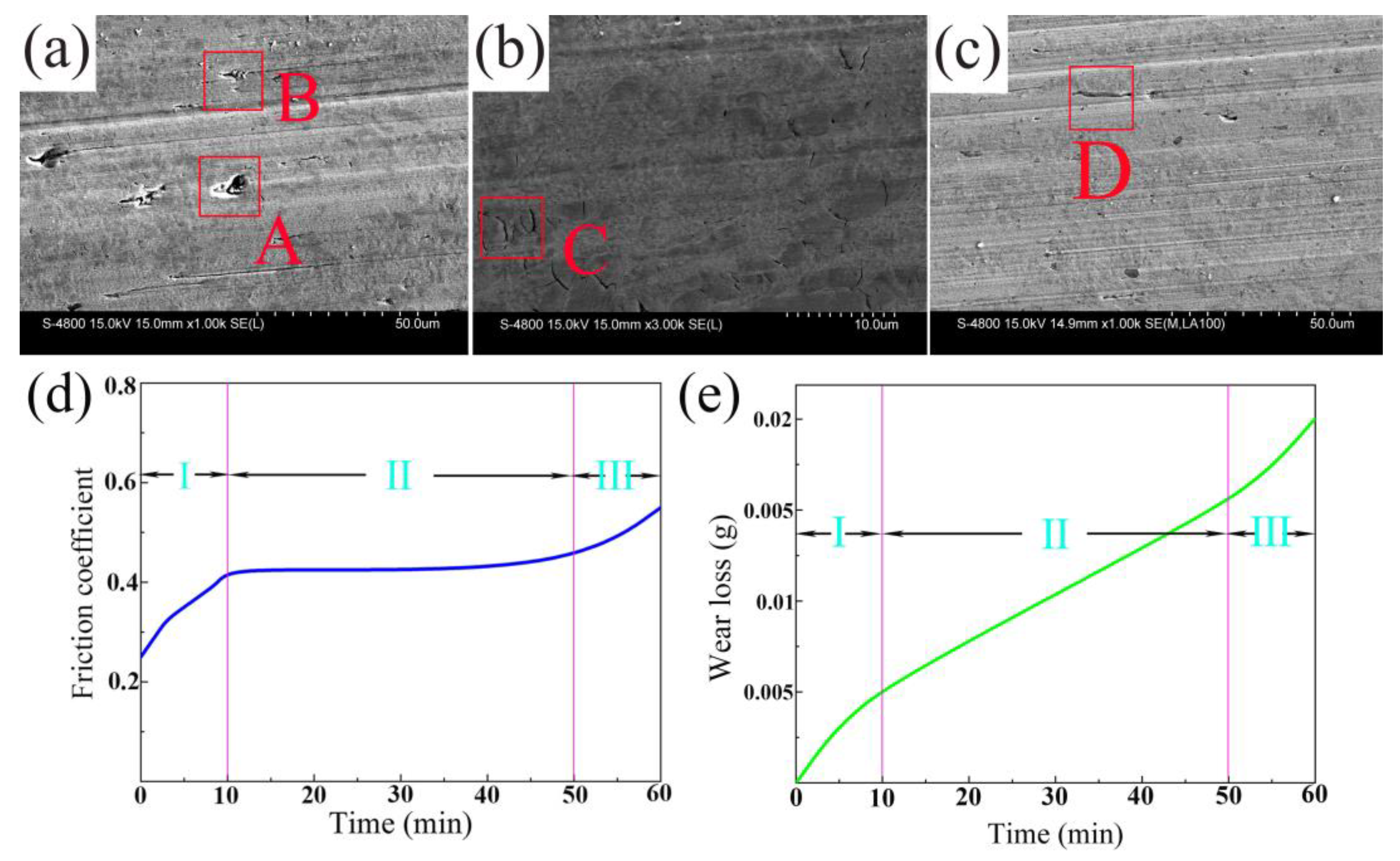
3.3.3. Wear
4. Conclusions
Author Contributions
Funding
Institutional Review Board Statement
Informed Consent Statement
Data Availability Statement
Conflicts of Interest
References
- Jain, A.S.; Chang, H.W.; Tang, X.H.; Hinckley, B.; Zhang, M.X. Refinement of primary carbides in hypereutectic high-chromium cast irons: A review. J. Mater. Sci. 2020, 56, 999–1038. [Google Scholar] [CrossRef]
- Siekaniec, D.; Kopycinski, D.; Tyrala, E.; Guzik, E.; Szczesny, A. Optimisation of Solidification Structure and Properties of Hypoeutectic Chromium Cast Iron. Materials 2022, 15, 6243. [Google Scholar] [CrossRef] [PubMed]
- Hadji, A.; Bouhamla, K.; Maouche, H. Improving wear properties of high-chromium cast Iron by manganese alloying. Int. J. Metalcast. 2016, 10, 43–55. [Google Scholar] [CrossRef]
- Filipovic, M.; Kamberovic, Z.; Korac, M. Solidification of high chromium white cast iron alloyed with vanadium. Mater. Trans. 2011, 52, 386–390. [Google Scholar] [CrossRef]
- Bedolla-Jacuinde, A.; Guerra, F.V.; Mejía, I.; Zuno-Silva, J.; Rainforth, M. Abrasive wear of V–Nb–Ti alloyed high-chromium white irons. Wear 2015, 332–333, 1006–1011. [Google Scholar] [CrossRef]
- Kana, A.Z.V.; Krutis, V. Effect of alloying elements on properties and structure of high chromium cast irons. Arch. Metall. Mater. 2018, 63, 609–614. [Google Scholar]
- Zhou, Y.; Yang, Y.; Yang, J.; Hao, F.; Li, D.; Ren, X.; Yang, Q. Effect of Ti additive on (Cr, Fe)7C3 carbide in arc surfacing layer and its refined mechanism. Appl. Surf. 2012, 258, 6653–6659. [Google Scholar] [CrossRef]
- Penagos, J.J.; Pereira, J.I.; Machado, P.C.; Albertin, E.; Sinatora, A. Synergetic effect of niobium and molybdenum on abrasion resistance of high chromium cast irons. Wear 2017, 376–377, 983–992. [Google Scholar] [CrossRef]
- Kopyciński, D.; Siekaniec, D.; Szczęsny, A.; Guzik, E.; Nowak, A. The effect of Fe-Ti inoculation on solidification, structure and mechanical properties of high chromium cast iron. Arch. Metall. Mater. 2017, 62, 2183–2187. [Google Scholar] [CrossRef]
- Maja, M.E.; Maruma, M.G.; Mampuru, L.A. Effect of niobium on the solidification structure and properties of hypoeutectic high-chromium white cast irons. J. S. Afr. Inst. Min. Metall. 2016, 116, 981–986. [Google Scholar] [CrossRef]
- Arnoldo, B.J.; Guerra, F.; Mejia, I.; Vera, U. Niobium additions to a 15%Cr–3%C white iron and its effects on the microstructure and on abrasive wear behavior. Metals 2019, 9, 1321. [Google Scholar]
- Zhou, X.; Li, G.; Shen, X.; Liu, Y. Tensile strength improvement of martensitic ODS steels with Zr and Hf additions. Mat. Sci. Engi. A 2022, 829, 142071. [Google Scholar] [CrossRef]
- Yang, Y.; Tan, L.; Bei, H.; Busby, J.T. Thermodynamic modeling and experimental study of the Fe–Cr–Zr system. J. Nucl. Mater. 2013, 441, 190–202. [Google Scholar] [CrossRef]
- Lei, J.W.; Wu, K.M.; Li, Y.; Hou, T.P.; Xie, X.; Misra, R.D.K. Effects of Zr addition on microstructure and toughness of simulated CGHAZ in high-strength low-alloy steels. J. Iron Steel Res. Int. 2019, 26, 1117–1125. [Google Scholar] [CrossRef]
- Zeng, W.; Zhou, M.; Yang, M.; Qiu, R. Effect of Zr on the microstructure and mechanical properties of 12Cr ferritic/martensitic steels. Fusion Eng. Des. 2022, 177, 113084. [Google Scholar] [CrossRef]
- Xing, J.D.; Gao, Y.M.; Wang, E.Z. Effect of phase stability on the wear resistance of white cast iron at 800 °C. Wear 2002, 252, 755–760. [Google Scholar] [CrossRef]
- Purba, R.H.; Shimizu, K.; Kusumoto, K.; Gaqi, Y.; Todaka, T. Effect of boron addition on three-body abrasive wear characteristics of high chromium based multi-component white cast iron. Mater. Chem. Phys. 2022, 275, 125–136. [Google Scholar] [CrossRef]
- You, M.A.; Xiulan, L.I.; Liu, Y.G.; Zhou, S.Y. Microstructure and properties of Ti-Nb-V-Mo alloyed high chromium cast iron. Natl. Acad. Sci. Lett. 2013, 36, 839–844. [Google Scholar]
- Gong, L.; Fu, H.; Zhi, X. Corrosion wear of hypereutectic high chromium cast iron: A review. Metals 2023, 13, 308. [Google Scholar] [CrossRef]
- Zhi, X.H.; Xing, J.D.; Gao, Y.M.; Fu, H.G.; Peng, J.Y.; Xiao, B. Effect of heat treatment on microstructure and mechanical properties of a Ti-bearing hypereutectic high chromium white cast iron. Mater. Sci. Eng. A 2007, 487, 171–179. [Google Scholar] [CrossRef]
- Liu, Q.; Zhang, H.; Wang, Q.; Nakajima, K. Effect of heat treatment on microstructure and mechanical properties of Ti-alloyed hypereutectic high chromium cast iron. ISIJ Int. 2012, 52, 2288–2294. [Google Scholar] [CrossRef]
- Chen, Z.; Guo, Q.; Fu, H.; Zhi, X. Effect of heat treatment on microstructure and properties of modified hypereutectic high chromium cast iron. Mater. Test. 2022, 64, 33–54. [Google Scholar] [CrossRef]
- Wiengmoon, A.; Chairuangsri, T.; Chomsang, N.; Poolthong, N.; Pearce, J.T.H. Effects of heat treatment on hardness and dry wear properties of a semi-solid processed Fe-27wt%Cr–2.9wt%C cast Iron. J. Mater. Sci. Technol. 2008, 24, 330–334. [Google Scholar]
- Zhang, D.; Hou, T.P.; Liang, X.; Zheng, P.; Zheng, Y.H.; Lin, H.F.; Wu, K.M. The structural, magnetic, electronic, and mechanical properties of orthogonal/hexagonal MC (M = Fe and Cr) carbides from first-principles calculations. Vacuum 2022, 203, 111–125. [Google Scholar] [CrossRef]
- Yangzhen, L.; Yehua, J.; Rong, Z. First-principles study on stability and mechanical properties of Cr7C3. Rare Metal Mat. Eng. 2014, 43, 2903–2907. [Google Scholar] [CrossRef]


| Element | Fe | Cr | Si | Mn | Mo | Ni | V | Ti | Nb | Zr | B | C | Possible Phases |
|---|---|---|---|---|---|---|---|---|---|---|---|---|---|
| A | 24.9 | 27.6 | 0.2 | 1.2 | 0 | 0.2 | 0 | 0 | 0 | 0 | 0 | 45.9 | M7C3 |
| B | 24 | 26 | 1.1 | 1.1 | 0.2 | 0.7 | 0 | 0 | 0 | 0 | 46.9 | 0 | M7C3 |
| C | 58.1 | 9.1 | 0.8 | 0.8 | 0 | 1.1 | 0 | 0 | 0 | 0 | 0 | 30.1 | A |
| D | 24.2 | 28.6 | 0 | 1.4 | 0.3 | 0.8 | 0 | 0 | 0 | 0 | 0 | 44.7 | M7C3 |
| E | 50.9 | 8.5 | 0.9 | 1.3 | 0 | 0.9 | 0 | 0 | 0 | 0 | 0 | 37.5 | M |
| F | 52.3 | 8.3 | 0.7 | 1.4 | 0 | 1 | 0 | 0 | 0 | 0 | 0 | 36.3 | M |
| G | 17.41 | 4.56 | 0.22 | 0.45 | 0.12 | 0.26 | 0.28 | 0.16 | 0 | 0 | 50.75 | 25.72 | M7C3 |
| H | 0.7 | 0 | 0 | 0 | 0 | 0 | 68.8 | 3.9 | 1.5 | 0.1 | 0 | 25.0 | (V, M)2C |
| I | 36.2 | 0 | 0 | 0 | 0 | 0 | 54.0 | 0.5 | 0.9 | 0.1 | 8.3 | 0 | V(Fe, M) |
| J | 0.6 | 0 | 0 | 0 | 0 | 0 | 3.4 | 11.1 | 1.5 | 29.9 | 35.3 | 18.2 | (Zr, M)(C, B) |
| K | 9.4 | 11.9 | 0.3 | 0.5 | 0 | 0.2 | 0.5 | 0.1 | 0.1 | 0 | 44.9 | 32.1 | M7C3 |
| L | 24.5 | 3.8 | 0.3 | 0.4 | 0 | 0.1 | 0.1 | 0 | 0 | 0.1 | 16.2 | 54.5 | A |
| M | 23.5 | 3.7 | 0.2 | 0.4 | 0 | 0.2 | 0.2 | 0.1 | 0 | 0.1 | 19.8 | 51.8 | M |
| N | 10.1 | 11.9 | 0.2 | 0.6 | 0.1 | 0.2 | 0.6 | 0.1 | 0.1 | 0 | 45.9 | 30.2 | M7C3 |
| Phase/System/SG | Parameters | HCCI | HCCI-VFC |
|---|---|---|---|
| Martensite | a (nm) | 0.286250(13) | 0.289869(17) |
| /Tetragonal | c (nm) | 0.289249(20) | 0.287309(18) |
| /I4/mmm (139) | V (×10−3 nm3) | 23.7 | 24.1 |
| Content (wt%) | 70.7 | 82.5 | |
| Austenite | a (nm) | 0.35829(7) | 0.3617(2) |
| /Cubic | V (×10−3 nm3) | 45.9 | 47.3 |
| /Fmm (225) | Content (wt%) | 6.0 | 0.9 |
| M7C3 | a (nm) | — | 0.45332(9) |
| /Orthogonal | b (nm) | — | 0.7014(3) |
| /Pnma (62) | c (nm) | — | 1.189(2) |
| V (×10−3 nm3) | — | 378.2 | |
| Content (wt%) | — | 7.9 | |
| M7C3 | a (nm) | 1.39084(7) | 1.4008(2) |
| /Hexagonal | c (nm) | 0.45028(7) | 0.454385(0) |
| /P63mc (186) | V (×10−3 nm3) | 754.3 | 772.1 |
| Content (wt%) | 23.3 | 8.7 |
| Sample | Alloy Hardness (HRC) | Matrix Hardness (HV) | ||||
|---|---|---|---|---|---|---|
| As-Cast | As-Quenched | Tempered | As-Cast | As-Quenched | Tempered | |
| HCCI | 48.6 ± 0.2 | 58.3 ± 0.4 | 60.9 ± 0.3 | 430.7 ± 4.1 | 690.3 ± 7.3 | 713.4 ± 5.4 |
| HCCI-VFC | 49.3 ± 0.6 | 59.6 ± 0.3 | 63.4 ± 0.2 | 464.8 ± 4.7 | 736.7 ± 7.4 | 763.2 ± 5.6 |
| Increased by (%) | 1.4 | 2.2 | 4.1 | 7.9 | 6.7 | 7.0 |
| Sample | Impact Toughness (J/cm2) | Composition of Impact Fracture | |||
|---|---|---|---|---|---|
| Fiber Zone Ratio (%) | Radiation Zone Ratio (%) | Shear Lip Zone Ratio (%) | Fracture Height (mm) | ||
| HCCI | 7.1 | 55.1 | 8.9 | 36.0 | 2.2 |
| HCCI-VFC | 8.3 | 33.6 | 28.3 | 38.1 | 2.4 |
| Increased by (%) | 16.9 | -39.0 | 218.0 | 5.8 | 9.1 |
Disclaimer/Publisher’s Note: The statements, opinions and data contained in all publications are solely those of the individual author(s) and contributor(s) and not of MDPI and/or the editor(s). MDPI and/or the editor(s) disclaim responsibility for any injury to people or property resulting from any ideas, methods, instructions or products referred to in the content. |
© 2023 by the authors. Licensee MDPI, Basel, Switzerland. This article is an open access article distributed under the terms and conditions of the Creative Commons Attribution (CC BY) license (https://creativecommons.org/licenses/by/4.0/).
Share and Cite
Liu, T.; Sun, J.; Xiao, Z.; He, J.; Shi, W.; Cui, C. Effect of Multi-Element Microalloying on the Structure and Properties of High Chromium Cast Iron. Materials 2023, 16, 3292. https://doi.org/10.3390/ma16093292
Liu T, Sun J, Xiao Z, He J, Shi W, Cui C. Effect of Multi-Element Microalloying on the Structure and Properties of High Chromium Cast Iron. Materials. 2023; 16(9):3292. https://doi.org/10.3390/ma16093292
Chicago/Turabian StyleLiu, Tao, Jibing Sun, Zhixia Xiao, Jun He, Weidong Shi, and Chunxiang Cui. 2023. "Effect of Multi-Element Microalloying on the Structure and Properties of High Chromium Cast Iron" Materials 16, no. 9: 3292. https://doi.org/10.3390/ma16093292