
Improved Tensile and Bond Properties through Novel Rod Constructions Based on the Braiding Technique for Non-Metallic Concrete Reinforcements
 ,
,  , , , ,
Abstract
:1. Introduction
2. Materials and Methods
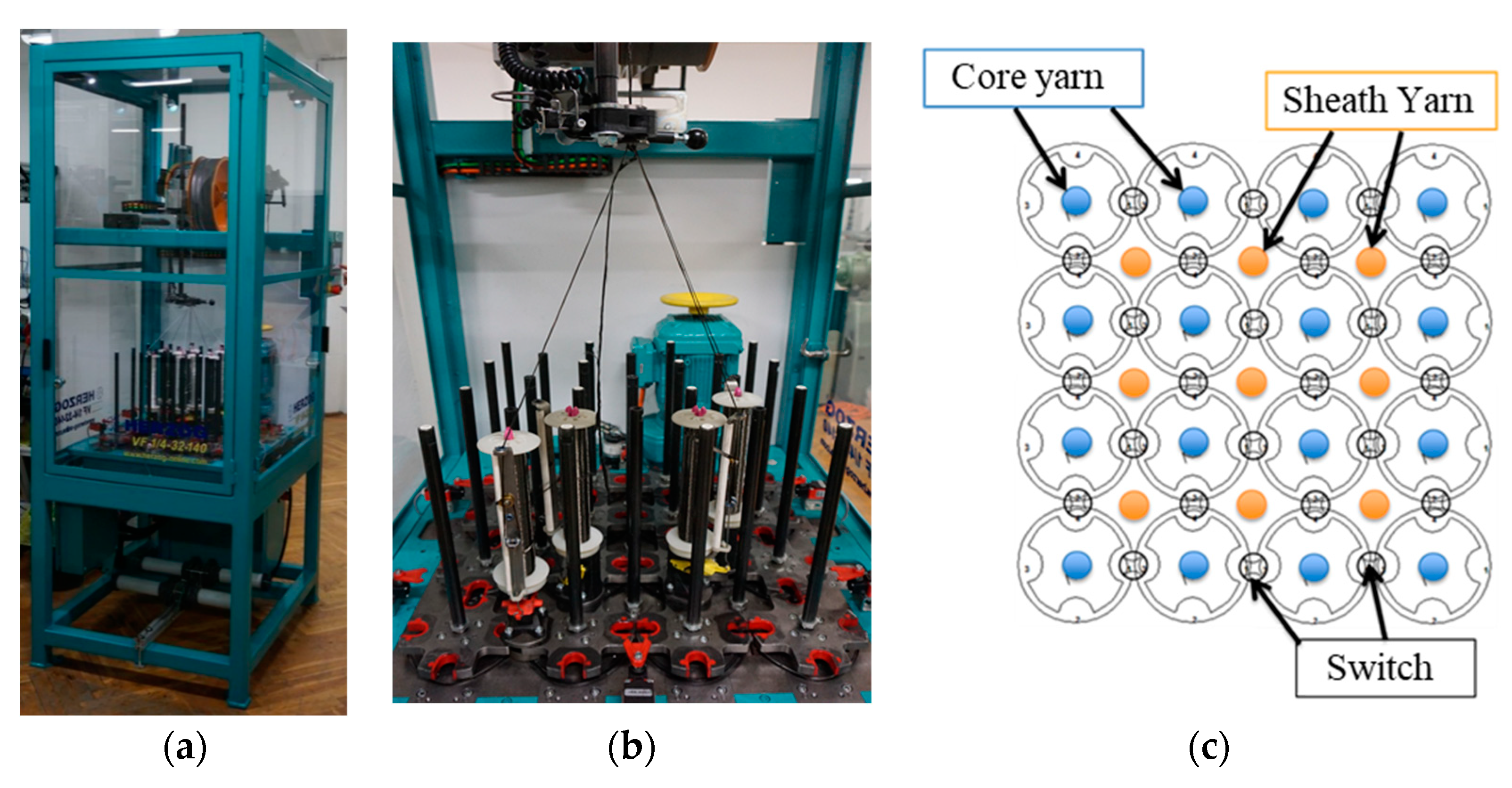
2.1. Braided Rods Composed of Carbon Fiber Heavy Tows
- 4 × 4 impellers to “park” several bobbins;
- Central control of the impellers;
- Up to 32 clappers and 24 pneumatic switching points;
- Clappers with closed ceramic yarn guides;
- 9 core inlet tubes Ø 8 mm between the impellers for core yarns;
- 16 drilled paddle wheel pillars for standing threads.
- Optimization of the bobbin design;
- Optimization of the deflection rollers with regard to surface properties and geometry;
- Optimization of the yarn tension compensation.
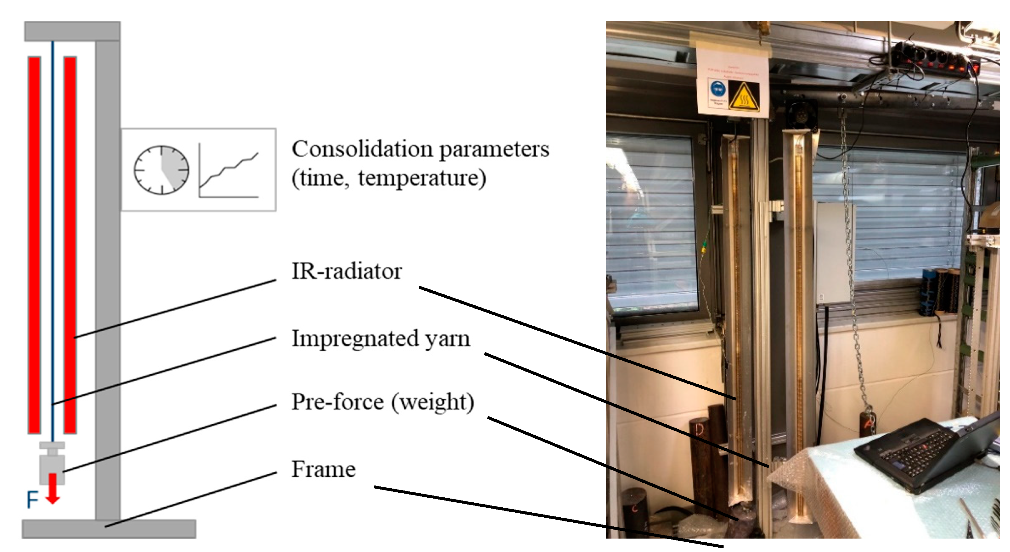
2.2. Impregnation and Consolidation
2.3. Concrete Matrix
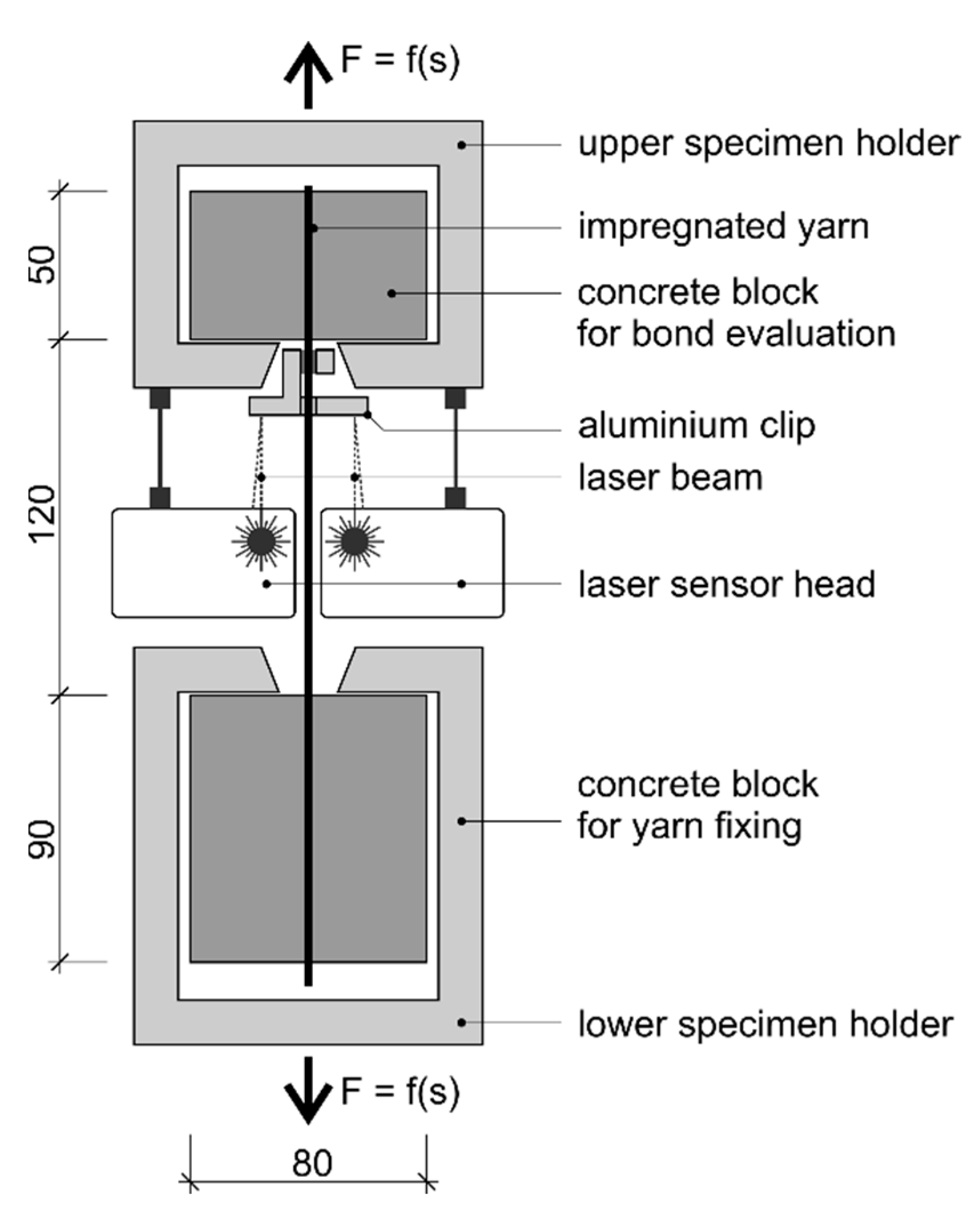
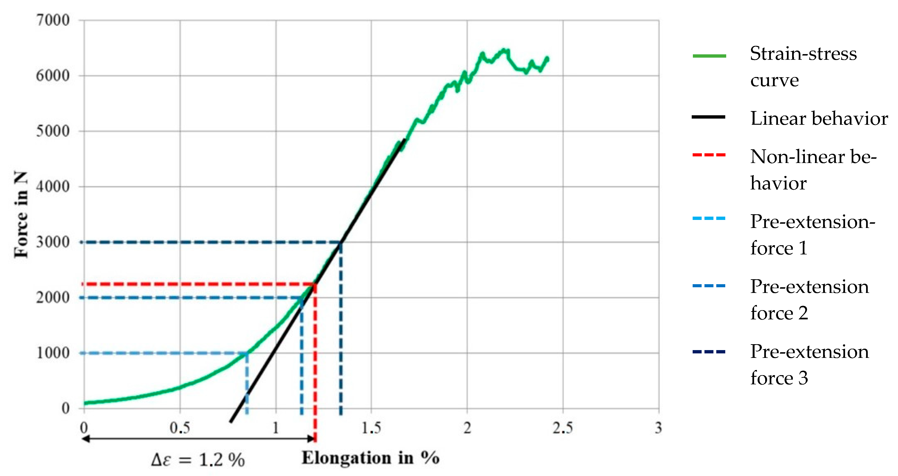
2.4. Characterization of the Rods’ Tensile Properties and Bond Behavior in Concrete as Well as Tensile Properties of the Composite
2.5. Specimens Manufacturing
3. Results and Discussions
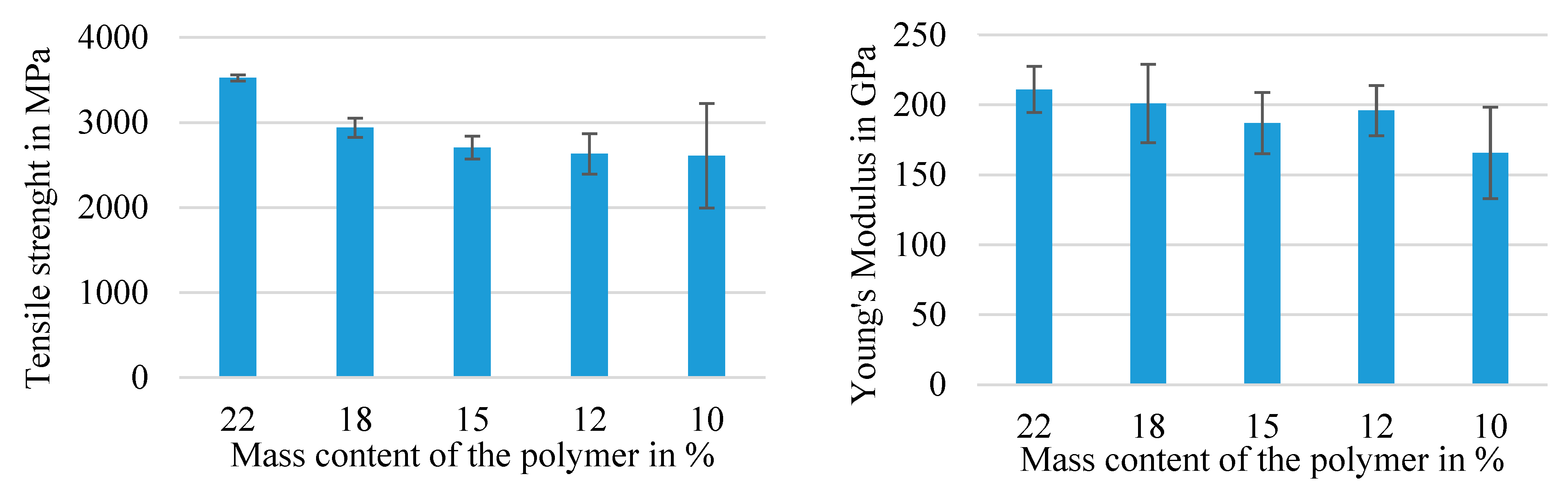
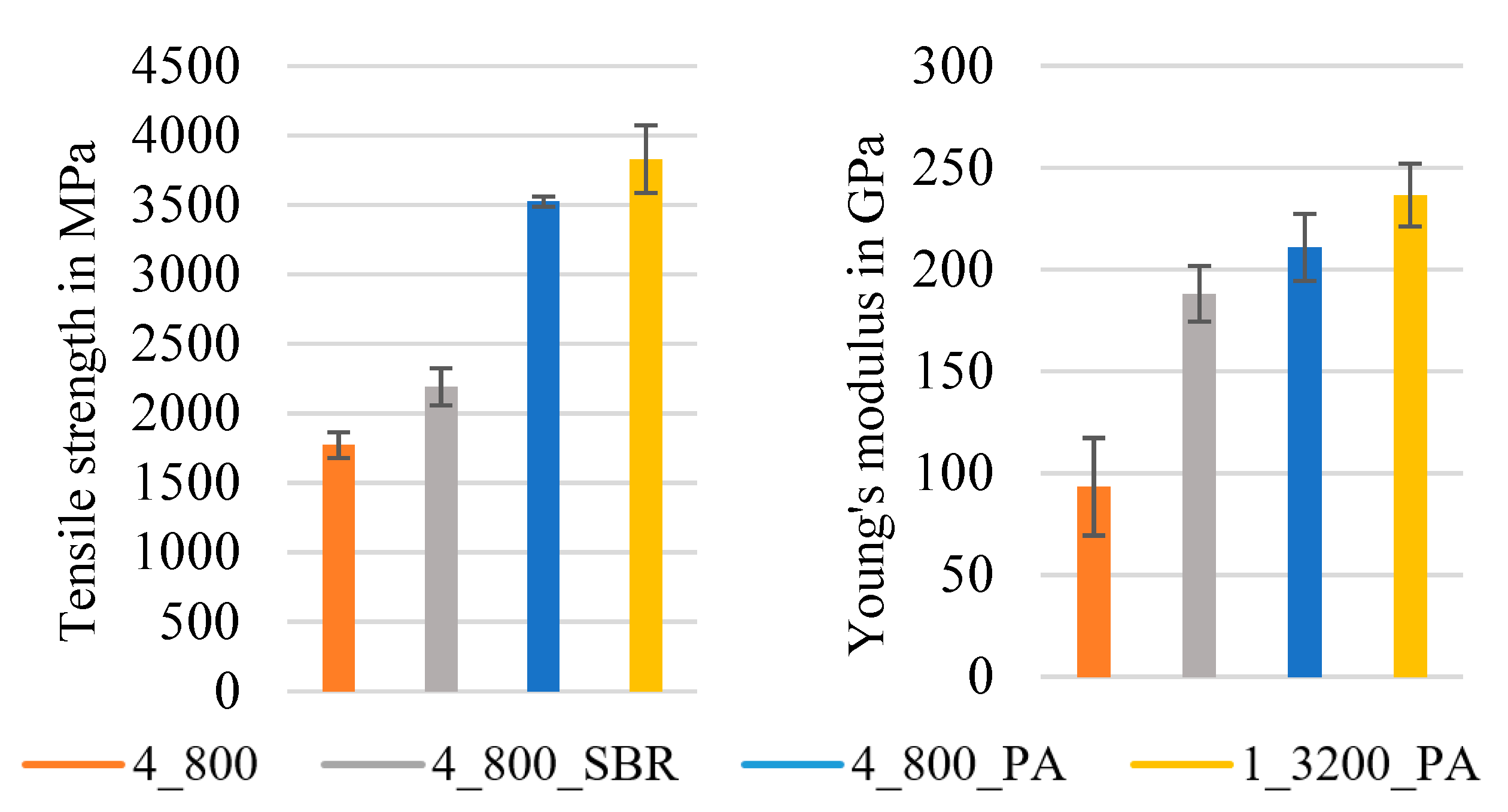
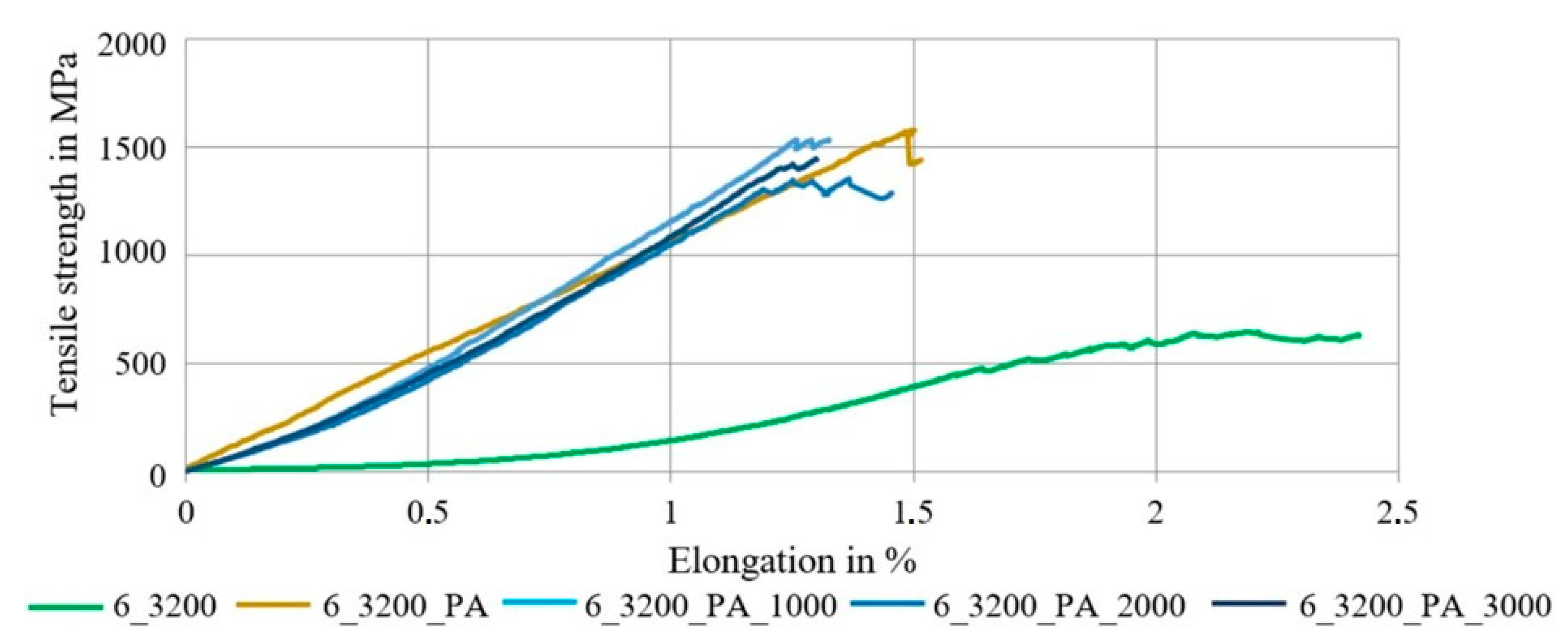
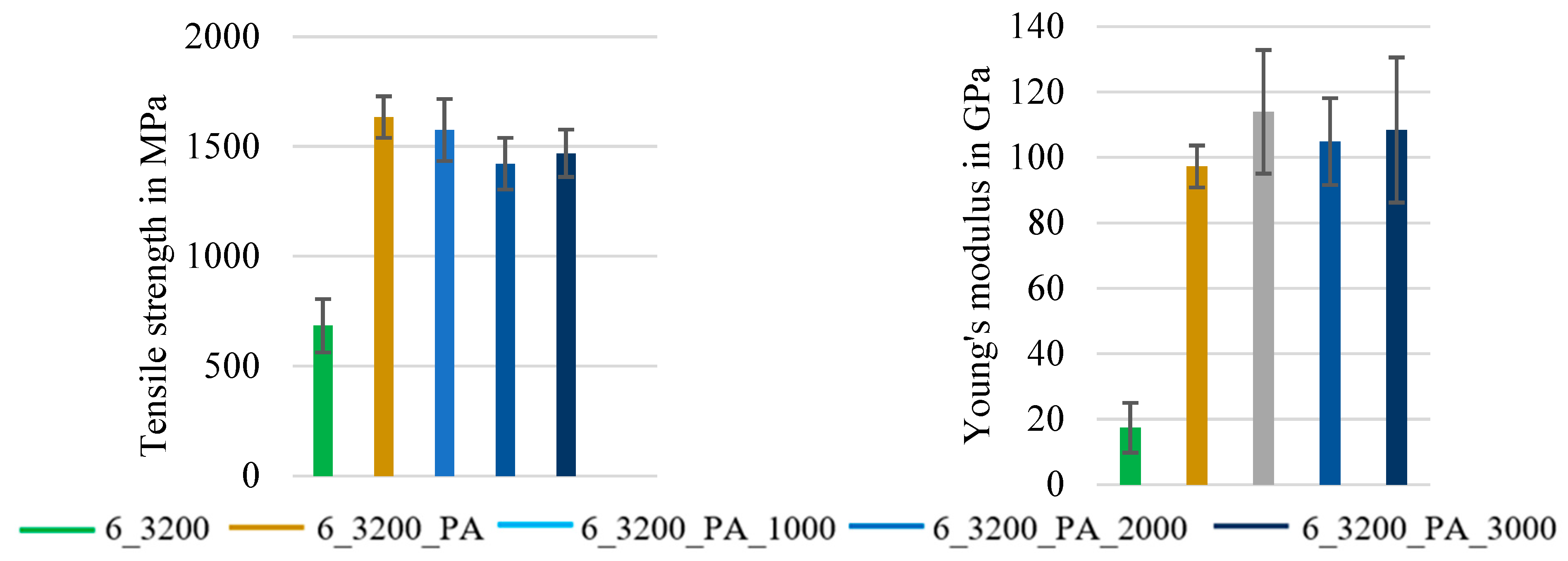
3.1. Tensile Properties
3.2. Micrographic Analysis
3.3. Tensile Properties of Concrete-Embedded Braided Rods
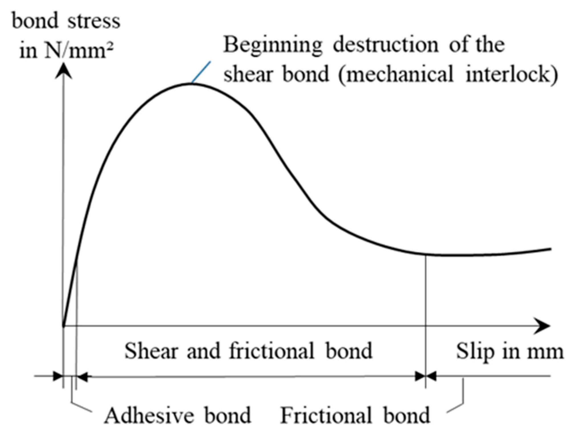
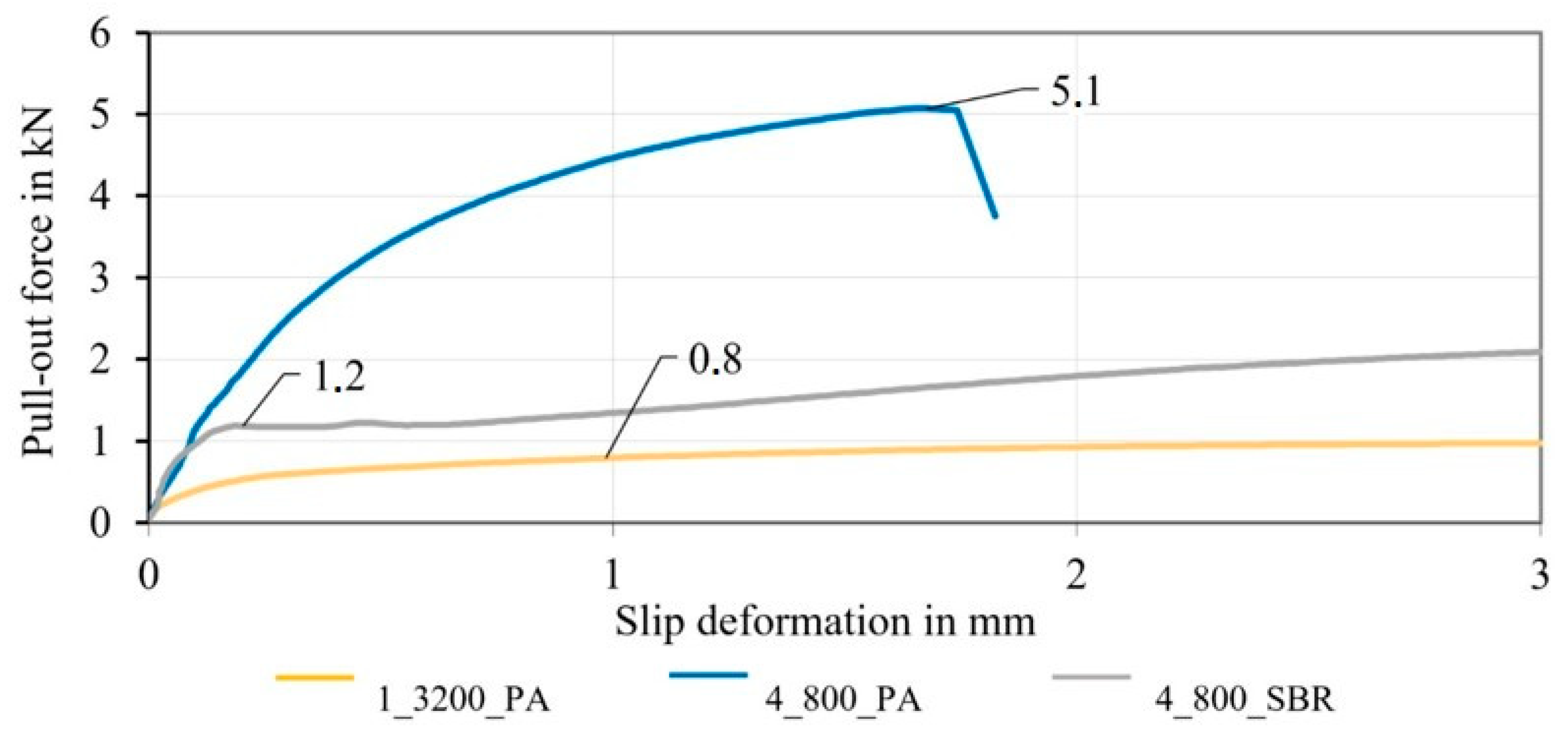
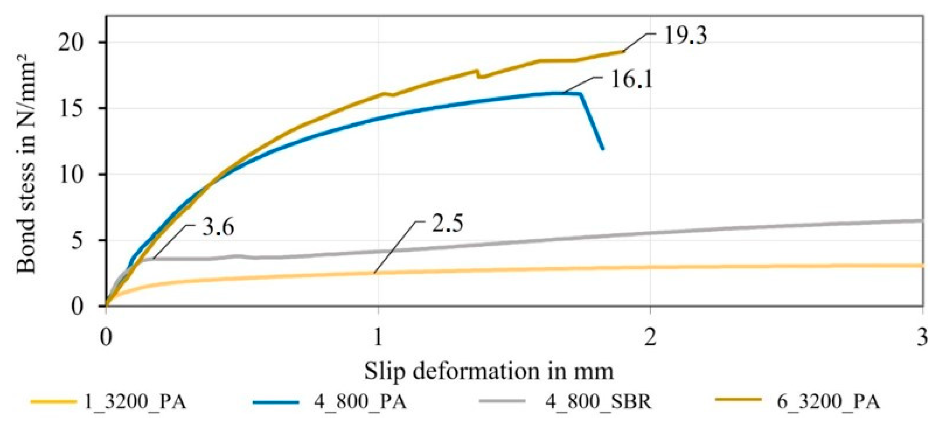
3.4. Bond Properties
4. Conclusions
5. Outlook
Author Contributions
Funding
Institutional Review Board Statement
Informed Consent Statement
Data Availability Statement
Conflicts of Interest
References
- Witsch, K. Klimakiller Beton: So will die Zementbranche Klimaneutral Werden. Handelsblatt 25 November 2020. Available online: https://www.handelsblatt.com/unternehmen/energie/klimaschutz-klimakiller-beton-so-will-die-deutsche-zementindustrie-co2-neutral-werden-/26652040.html (accessed on 29 April 2022).
- vdz gGmbH: CO2 Capturing in Cement Production. Available online: https://www.vdz-online.de/fileadmin/Forschung/01_Ruppert_2019_08_22_CO2_capturing_in_cement_production_EN.pdf (accessed on 22 September 2022).
- Seifert, W.; Lieboldt, M. Ressourcenverbrauch im globalen Stahlbetonbau und Potenziale der Carbonbetonbauweise. Beton Stahlbetonbau 2020, 115, 469–478. [Google Scholar] [CrossRef]
- Friese, D.; Scheurer, M.; Hahn, L.; Gries, T.; Cherif, C. Textile reinforcement structures for concrete construction applications—A review. J. Compos. Mater. 2022, 56, 002199832211271. [Google Scholar] [CrossRef]
- Hahn, L.; Rittner, S.; Nuss, D.; Ashir, M.; Cherif, C. Development of Methods to Improve the Mechanical Performance of Coated Grid-Like Non-Crimp Fabrics for Construction Applications. Fibres Text. East. Eur. 2019, 27, 51–58. [Google Scholar] [CrossRef]
- Hahn, L. Entwicklung einer In-situ-Beschichtungs- und Trocknungstechnologie für multiaxiale Gelegestrukturen mit hohem Leistungsvermögen. Ph.D. Thesis, Technische Universität Dresden, Dresden, Germany, 2020. [Google Scholar]
- Jesse, F. Tragverhalten von Filamentgarnen in zementgebundener Matrix. Ph.D. Thesis, Technische Universität Dresden, Dresden, Germany, 2004. [Google Scholar]
- Kruppke, I.; Butler, M.; Schneider, K.; Hund, R.-D.; Mechtcherine, V.; Cherif, C. Carbon Fibre Reinforced Concrete: Dependency of Bond Strength on Tg of Yarn Impregnating Polymer. Mater. Sci. Appl. 2019, 10, 328–348. [Google Scholar] [CrossRef] [Green Version]
- Curbach, M.; May, S.; Egbert, M.; Schumann, A.; Schütze, E.; Wagner, E. Verstärken mit Carbonbeton. In BetonKalender 2022; John Wiley & Sons, Ltd: Hoboken, NJ, USA, 2022; pp. 761–804. [Google Scholar]
- Köckritz, U. In-Situ-Polymerbeschichtung zur Strukturstabilisierung offener nähgewirkter Gelege. Ph.D. Thesis, Technische Universität Dresden, Dresden, Germany, 2007. [Google Scholar]
- Curbach, M.; Hauptenbuchner, B.; Ortlepp, R.; Weiland, S. Textilbewehrter Beton zur Verstärkung eines Hyparschalentragwerks in Schweinfurt. Beton Stahlbetonbau 2007, 102, 353–361. [Google Scholar] [CrossRef]
- Hegger, J.; Kulas, C.; Horstmann, M. Realization of TRC Façades with Impregnated AR-Glass Textiles. Polym. Concr. 2011, 466, 121–130. [Google Scholar] [CrossRef]
- Schütze, E.; Curbach, M. Zur experimentellen Charakterisierung des Verbundverhaltens von Carbonbeton mit Spalten als maßgeblichem Versagensmechanismus/Experimental characterisation of the bond behaviour of carbon reinforced concrete with concrete splitting as significant failure mode. Bauingenieur 2019, 94, 133–141. [Google Scholar] [CrossRef]
- Lorenz, E. Endverankerung und Übergreifung textiler Bewehrungen in Betonmatrices. Ph.D. Thesis, Fakultät Bauingenieurwesen, Dresden, Germany, 2014. [Google Scholar]
- Bielak, J.; Spelter, A.; Will, N.; Claßen, M. Verankerungsverhalten textiler Bewehrungen in dünnen Betonbauteilen. Beton Stahlbetonbau 2018, 113, 515–524. [Google Scholar] [CrossRef]
- Preinstorfer, P.; Kromoser, B.; Kollegger, J. Kategorisierung des Verbundverhaltens von Textilbeton/Categorisation of the bond behaviour of textile reinforced concrete. Bauingenieur 2019, 94, 416–424. [Google Scholar] [CrossRef]
- Banholzer, B. Bond Behaviour of a Multi-Filament Yarn Embedded in a Cementitious Matrix. Ph.D. Thesis, RWTH Aachen University, Aachen, Germany, 2004. [Google Scholar]
- Penzel, P.; May, M.; Hahn, L.; Cherif, C.; Curbach, M.; Mechtcherine, V. Tetrahedral Profiled Carbon Rovings for Concrete Reinforcements. Text. Mater. 2022, 333, 173–182. [Google Scholar] [CrossRef]
- Li, Y.; Bielak, J.; Hegger, J.; Chudoba, R. An incremental inverse analysis procedure for identification of bond-slip laws in composites applied to textile reinforced concrete. Compos. Part B Eng. 2018, 137, 111–122. [Google Scholar] [CrossRef]
- Waldmann, M.; Rittner, S.; Cherif, C. DE 10 2017 107 948 A1. Bewehrungsstab zum Einbringen in eine Betonmatrix Sowie Dessen Herstellungsverfahren, ein Bewehrungssystem aus Mehreren Bewehrungsstäben Sowie ein Betonbauteil. 12.04.17. Available online: https://patentscope.wipo.int/search/de/detail.jsf?docId=WO2018189345 (accessed on 27 February 2023).
- Penzel, P.; May, M.; Hahn, L.; Scheerer, S.; Michler, H.; Butler, M.; Waldmann, M.; Curbach, M.; Cherif, C.; Mechtcherine, V. Bond Modification of Carbon Rovings through Profiling. Materials 2022, 15, 5581. [Google Scholar] [CrossRef] [PubMed]
- Böhm, R.; Thieme, M.; Wohlfahrt, D.; Wolz, D.; Richter, B.; Jäger, H. Reinforcement Systems for Carbon Concrete Composites Based on Low-Cost Carbon Fibers. Fibers 2018, 6, 56. [Google Scholar] [CrossRef] [Green Version]
- Schumann, A.; May, M.; Schladitz, F.; Scheerer, S.; Curbach, M. Carbonstäbe im Bauwesen. Beton Stahlbetonbau 2020, 115, 962–971. [Google Scholar] [CrossRef]
- Schumann, A. Experimentelle Untersuchungen des Verbundverhaltens von Carbonstäben in Betonmatrices. Ph.D. Thesis, Technische Universität Dresden, Institut für Massivbau, Dresden, Germany, 2020. [Google Scholar]
- Kolkmann, A.; Wulfhorst, B. Garnstrukturen für den Einsatz in textilbewehrtem Beton (Lehrstuhl für Textilmaschinenbau und Institut für Textiltechnik). Available online: http://publications.rwth-aachen.de/record/102203 (accessed on 27 February 2023).
- Kolkmann, A. Methoden zur Verbesserung des Inneren und äußeren Verbundes Technischer Garne zur Bewehrung zementgebundener Matrices. Ph.D. Thesis, RWTH Aachen University, Aachen, Germany, 2008. [Google Scholar]
- CARBOCON GMBH: CARBOrefit®—Verfahren zur Verstärkung von Stahlbeton mit Carbonbeton: Allgemein bauaufsichtliche Zulassung/Allgemeine Bauartgenehmigung. 2021. Available online: https://cloud.carborefit.de/index.php/s/PgMiAwyYMTz8Gse?dir=undefined&path=%2FCARBOrefit%C2%AE%20Zulassung&openfile=27808 (accessed on 27 February 2023).
- Schneider, K.; Michel, A.; Liebscher, M.; Mechtcherine, V. Verbundverhalten mineralisch gebundener und polymergebundener Bewehrungsstrukturen aus Carbonfasern bei Temperaturen bis 500 °C. Beton Stahlbetonbau 2018, 113, 886–894. [Google Scholar] [CrossRef]
- Teijin Limited. Teijin Carbon Europe GmbH: Tenax Filament: YarnProduct Datasheet; Teijin Limited: Tokyo, Japan, 2020. [Google Scholar]
- ISO 3341:2000-05; Textilglas-Garne-Bestimmung der Reißkraft und Bruchdehnung. Beuth Publishing Din: Berling, Germany.
- CHT Germany GmbH: TECOSIT CC 1000: Technical Datasheet; CHT Germany GmbH: Tübingen, Germany, 2022.
- Lefatex Chemie GmbH: Lefasol VL 90. Technical Datasheet; Lefatex Chemie GmbH: Brüggen, Germany, 2017.
- DIN EN 196-1:2016; Prüfverfahren für Zement-Teil 1: Bestimmung der Festigkeit. Beuth Publishing Din: Berling, Germany.
- DIN EN ISO 10618:2004-11; Kohlenstofffasern—Bestimmung des Zugverhaltens von harzimprägnierten Garnen. Beuth Publishing Din: Berling, Germany.


| Topic | State of the Art | References |
|---|---|---|
| Basic properties of carbon-reinforced concrete (CRC) | Use of carbon filament yarns with smooth surface structure; use of warp knitted grid-like structures with low rod count; high tensile properties; minimal structural elongation for initial load transfer with concrete matrix | [4,5,7,9,10,11,12,27] |
| Bond properties of CRC | Mainly adhesive bond; no dominant form fit or shear bond; yarn pull-out due to insufficient bonding properties; increased bond lengths for load transfer | [8,13,14,15,16,17,18,19,21,22,23,24,28] |
| Profiled textile reinforcement structures | Modified yarn structure by twisting and cabling; increased inner bond by fiber friction; no sufficient outer bond; surface profiling of thick rebars through additive/subtractive methods, reduced shear resistance and material efficiency; profiling through reshaping with defined bond properties | [18,20,21,23,25,26] |
| Properties of the Carbon Fiber Heavy Tows | ||||||
|---|---|---|---|---|---|---|
| Product Name | Filaments in k | Count in Tex | Density in g/cm³ | Area in mm² | Tensile Strength in MPa | Young’s Modulus in Gpa |
| Tenax®-E HTS45 E23 | 12 | 800 | 1.77 | 0.45 | 1632 | 219 |
| Tenax®-E STS40 E23 | 48 | 3200 | 1.77 | 1.81 | 1687 | 232 |
| Overview of Dry Braided Rod | |||||
|---|---|---|---|---|---|
| Rod Type | Sample Designation | Count in Tex | Braiding Structure | Pitch Length in mm | Illustration |
| Braided rod | 4_800 | 4 × 800 | 4-strand flat braid | 120 |  |
| 6_3200 | 6 × 3200 | 6-strand flat braid | 120 |  | |
| Overview of the Impregnation Agents | ||||
|---|---|---|---|---|
| Product Name | Characteristics | Base Material | Solid Content in % | Linking Temperature in °C |
| TECOSIT CC 1000 (CHT Germany GmbH) | Aqueous polymer dispersion | Polyacrylate (PA) | 47 ± 1 | 160 |
| Lefasol VL 90 (Lefatex Chemie GmbH) | Styrene-butadiene dispersion | Styrene-butadiene rubber (SBR) | 50 ± 1 | 130–160 |
| Overview of Samples with Impregnation | |||||
|---|---|---|---|---|---|
| Material Type | Sample Designation | Rod Count in tex | Impregnation Agent | Polymer Content in Mass % | Pre-Extension Force in N |
| Impregnated roving as reference | |||||
| Impregnated roving | 1_3200_PA | 1 × 3200 | PA | ~22 | 2 |
| Impregnated braided rods with low count | |||||
| Impregnated braided rod | Variation in impregnation agent | ||||
| 4_800_SBR | 4 × 800 | SBR | ~22 | 2 | |
| 4_800_PA | 4 × 800 | PA | ~22 | 2 | |
| Variation in solid content | |||||
| 4_800_PA_18 | 4 × 800 | PA | ~18 | 2 | |
| 4_800_PA_15 | 4 × 800 | PA | ~15 | 2 | |
| 4_800_PA_12 | 4 × 800 | PA | ~12 | 2 | |
| 4_800_PA_10 | 4 × 800 | PA | ~10 | 2 | |
| Impregnated braided rods with high count | |||||
| Impregnated braided rod | 6_3200_PA | 6 × 3200 | PA | ~22 | 20 |
| Variation in Pre-Extension force | |||||
| 6_3200_PA_1000 | 6 × 3200 | PA | ~22 | 1000 | |
| 6_3200_PA_2000 | 6 × 3200 | PA | ~22 | 2000 | |
| 6_3200_PA_3000 | 6 × 3200 | PA | ~22 | 3000 | |
| Overview of Braided Rods | ||
|---|---|---|
| Sample Designation | Rod Count in Tex | Illustration |
| 1_3200_PA | 1 × 3200 |  |
| 4_800_PA | 4 × 800 |  |
| 6_3200_PA | 6 × 3200 |  |
| Characteristics of the Concrete Matrix | |||
|---|---|---|---|
| Product Name | Maximum Grain Size in mm | Compressive Strength in MPa | Flexural Strength in MPa |
| BMK 45-220-2 [21] | 2 | ≥105 | ≥11.5 |
| TF 10 CARBOrefit® fine concrete [27] | 1 | ≥80 | ≥6 |
| Micrographic Analysis and Geometry Parameters of Different Reinforcement Rods | |||
|---|---|---|---|
| Rod Type | Properties | Values | Illustration |
| 1_3200_PA | Total rod count in tex | 3200 |  |
| Comparable diameter in mm | 2.0 | ||
| Circumference in mm | 6.3 | ||
| Polymer content in mass.-% | ~22 | ||
| 4_800_PA | Total rod count in tex | 3200 |  |
| Comparable diameter in mm | 2.0 | ||
| Circumference in mm | 6.3 | ||
| Polymer content in mass.-% | ~22 | ||
| 6_3200_PA | Total rod count in tex | 19,200 |  |
| Comparable diameter in mm | 4.5 | ||
| Circumference in mm | 14.1 | ||
| Polymer content in mass.-% | ~22 | ||
| Computer-Supported Micrographic Analysis | ||
|---|---|---|
| Real Microsection | Components | Colored Microsection |
 | ||
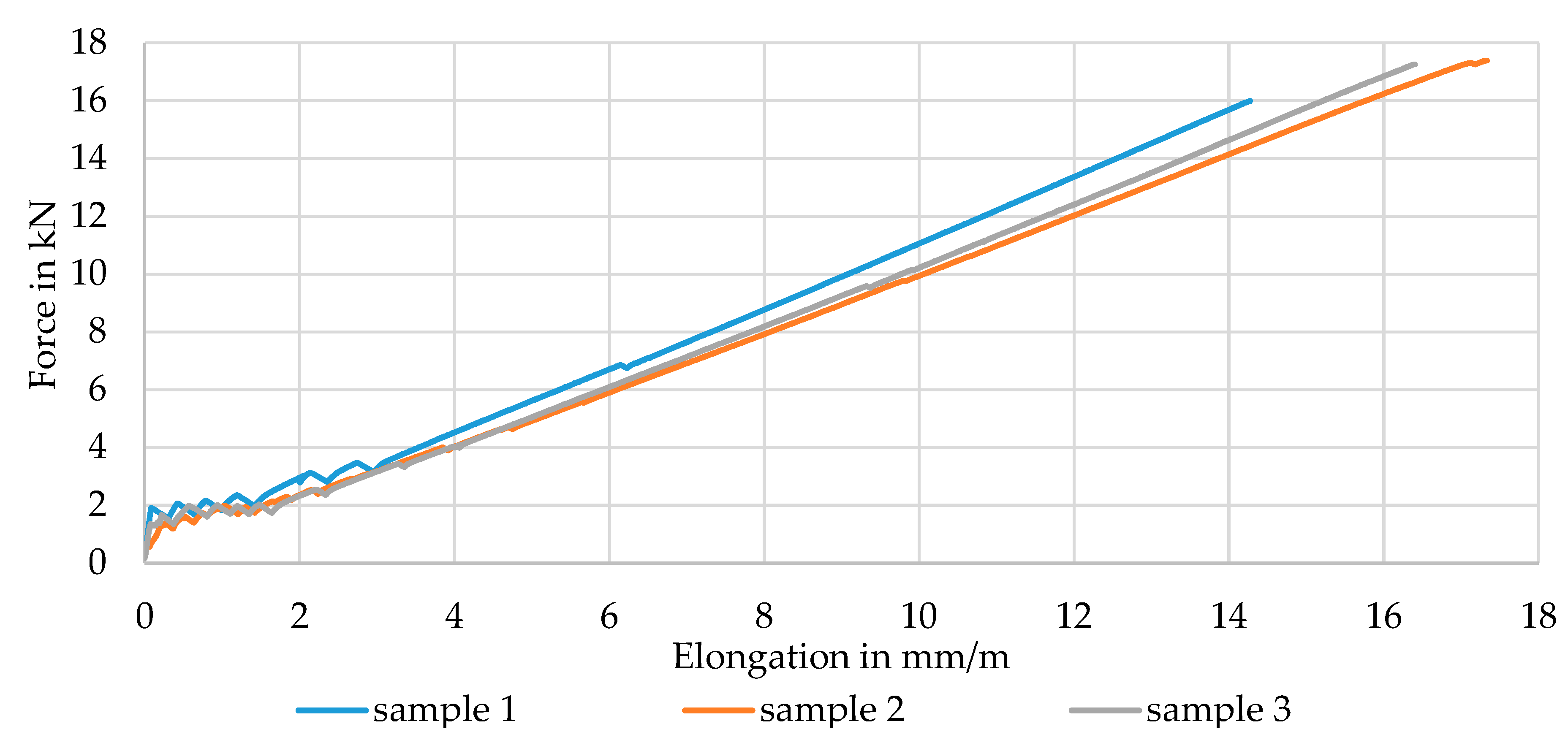
| Sample | First Crack in kN | Crack- Count | Splitting/ Cracking | Longitudinal Crack | Failure Force in kN | Tensile Strength in MPa | Failure Pattern |
|---|---|---|---|---|---|---|---|
| 1 | 1.91 | 7 | Cracking at failure | at failure | 16.00 | 2946 | complete spalling |
| 2 | 1.37 | 9 | 17.40 | 3204 | |||
| 3 | 1.49 | 9 | 17.27 | 3174 | |||
| Mean | 1.59 | 8 | 16.89 | 3110 |
Disclaimer/Publisher’s Note: The statements, opinions and data contained in all publications are solely those of the individual author(s) and contributor(s) and not of MDPI and/or the editor(s). MDPI and/or the editor(s) disclaim responsibility for any injury to people or property resulting from any ideas, methods, instructions or products referred to in the content. |
© 2023 by the authors. Licensee MDPI, Basel, Switzerland. This article is an open access article distributed under the terms and conditions of the Creative Commons Attribution (CC BY) license (https://creativecommons.org/licenses/by/4.0/).
Share and Cite
Abdkader, A.; Penzel, P.; Friese, D.; Overberg, M.; Hahn, L.; Butler, M.; Mechtcherine, V.; Cherif, C. Improved Tensile and Bond Properties through Novel Rod Constructions Based on the Braiding Technique for Non-Metallic Concrete Reinforcements. Materials 2023, 16, 2459. https://doi.org/10.3390/ma16062459
Abdkader A, Penzel P, Friese D, Overberg M, Hahn L, Butler M, Mechtcherine V, Cherif C. Improved Tensile and Bond Properties through Novel Rod Constructions Based on the Braiding Technique for Non-Metallic Concrete Reinforcements. Materials. 2023; 16(6):2459. https://doi.org/10.3390/ma16062459
Chicago/Turabian StyleAbdkader, Anwar, Paul Penzel, Danny Friese, Matthias Overberg, Lars Hahn, Marko Butler, Viktor Mechtcherine, and Chokri Cherif. 2023. "Improved Tensile and Bond Properties through Novel Rod Constructions Based on the Braiding Technique for Non-Metallic Concrete Reinforcements" Materials 16, no. 6: 2459. https://doi.org/10.3390/ma16062459