
Mechanical and Surface Characteristics of Selective Laser Melting-Manufactured Dental Prostheses in Different Processing Stages
 , , , and
Abstract
:1. Introduction
2. Materials and Methods
2.1. Materials and Technologies Used
- -
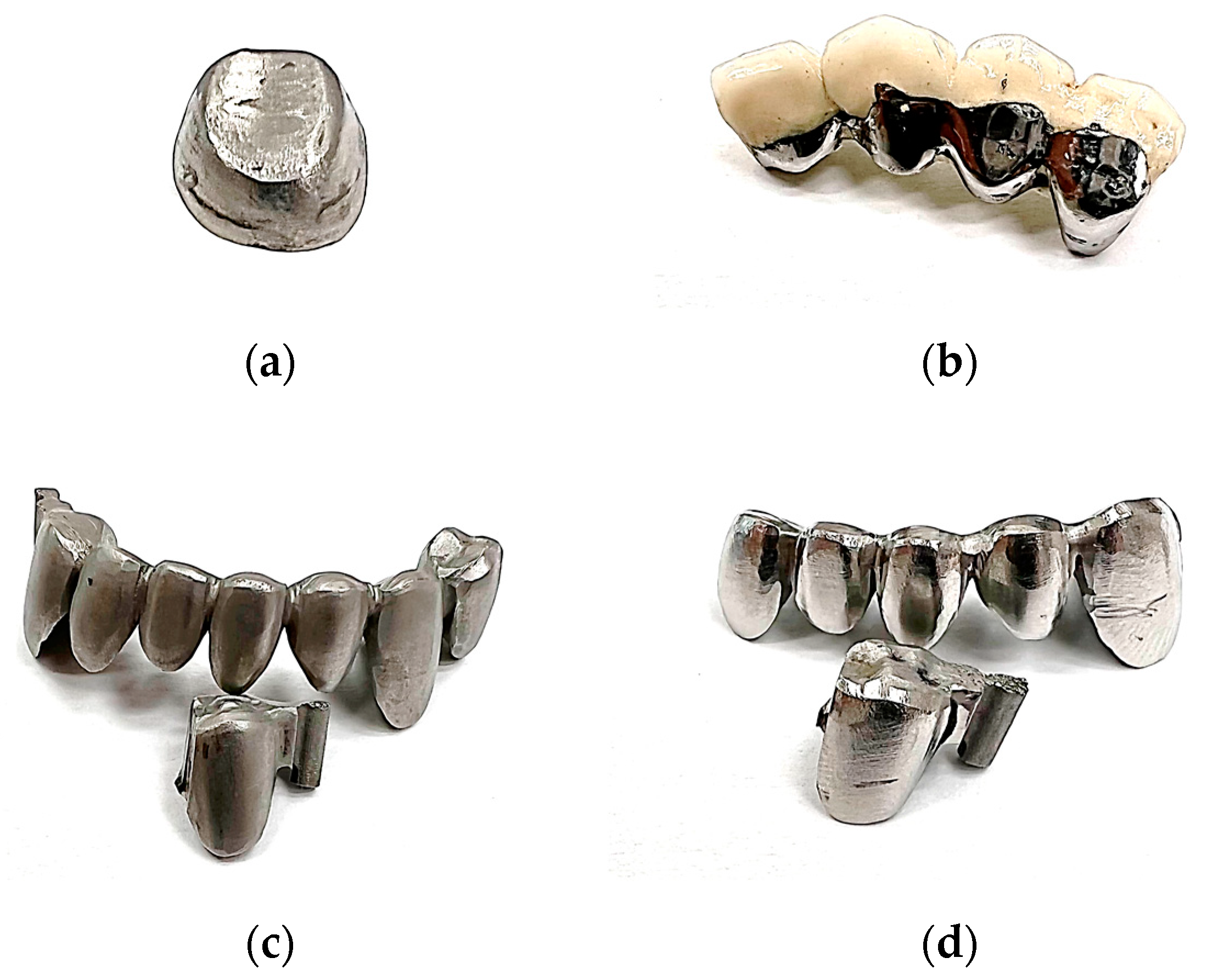
- Dental crown made by SLM from a Ni-Cr alloy in a preliminary finished state (Figure 1a).
- -
- The mechanical substructure made of a Co-Cr alloy within a metal–ceramic prosthesis, the post-processing state is in polishing conditions and it is practically ready for functional use (Figure 1b).
- -
- Complex prosthesis consisting of several dental structures made by SLM from a Co-Cr alloy in a preliminary finished state. For the mechanical tests, a unitary specimen was used that was sectioned from the entire prosthesis in order not to affect the compliance of the samples and fix them better on the experimental stand platform (Figure 1c).
- -
- Complex prosthesis consisting of several dental structures made by SLM of a Co-Cr alloy in a polished state. For the same reasons as in the case of the finished Co-Cr prosthesis, a unitary specimen of the dental structure was used, which was sectioned from the entire prosthesis (Figure 1d).

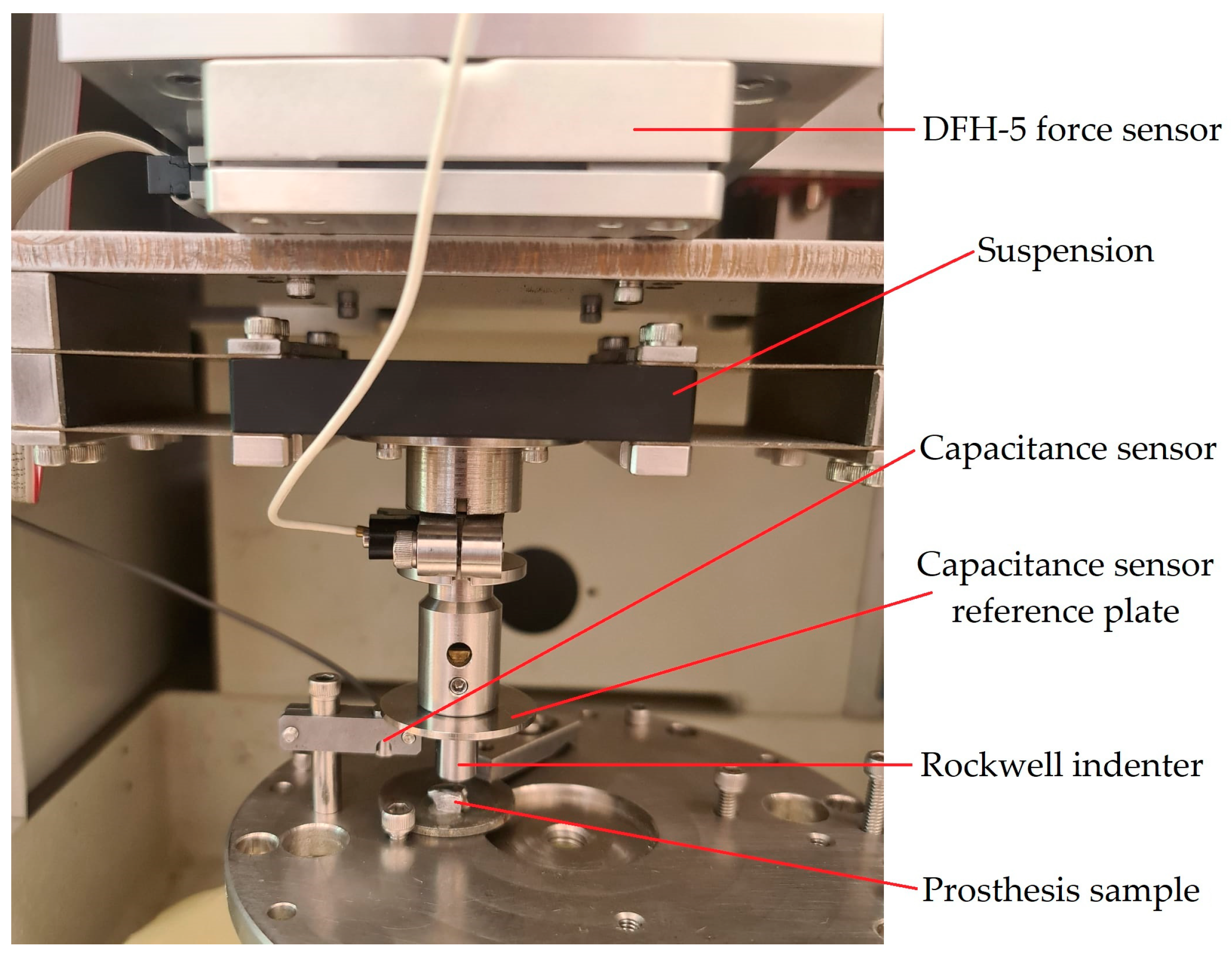
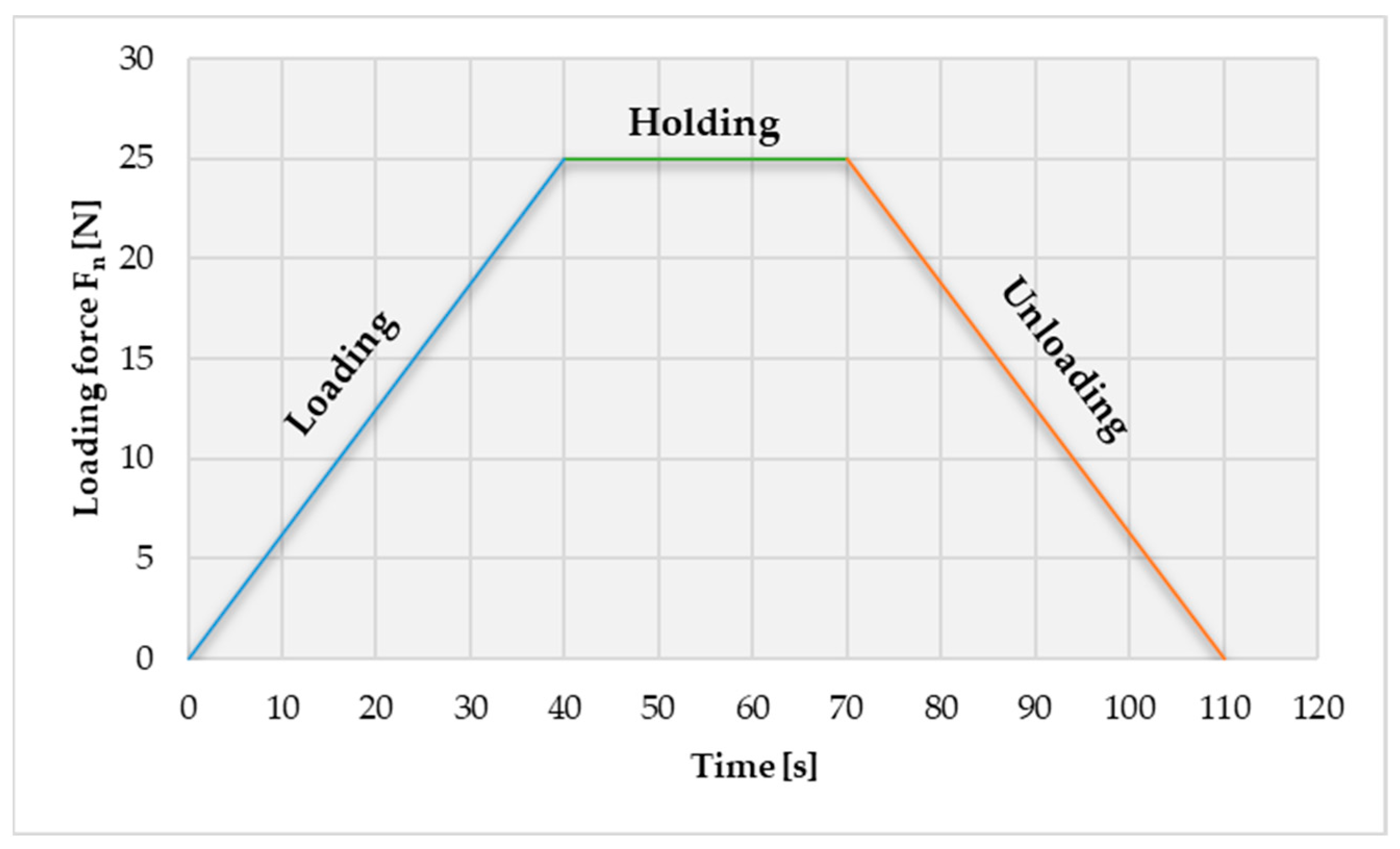
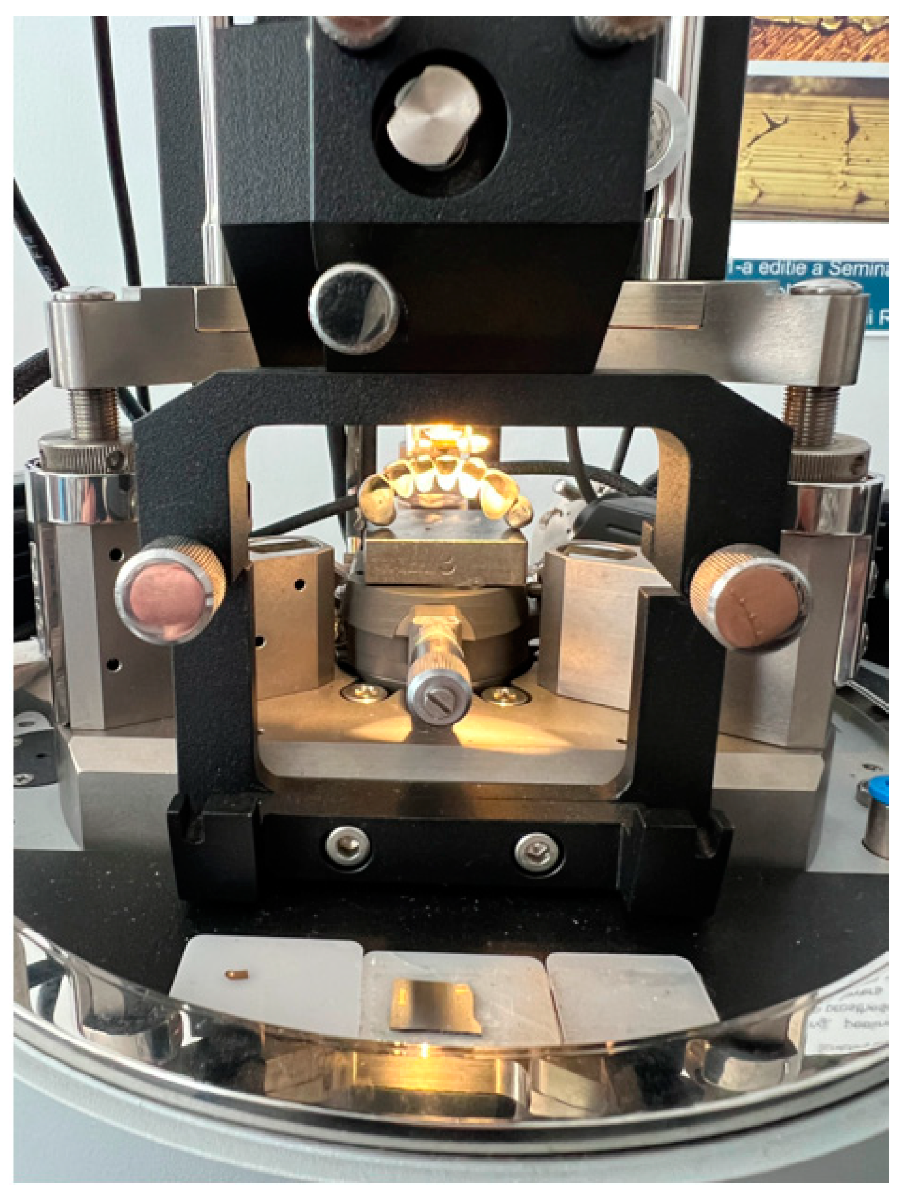
2.2. Indentation Test of Dental Prostheses
2.3. Surface Characteristics Measurement of Dental Prostheses
3. Results
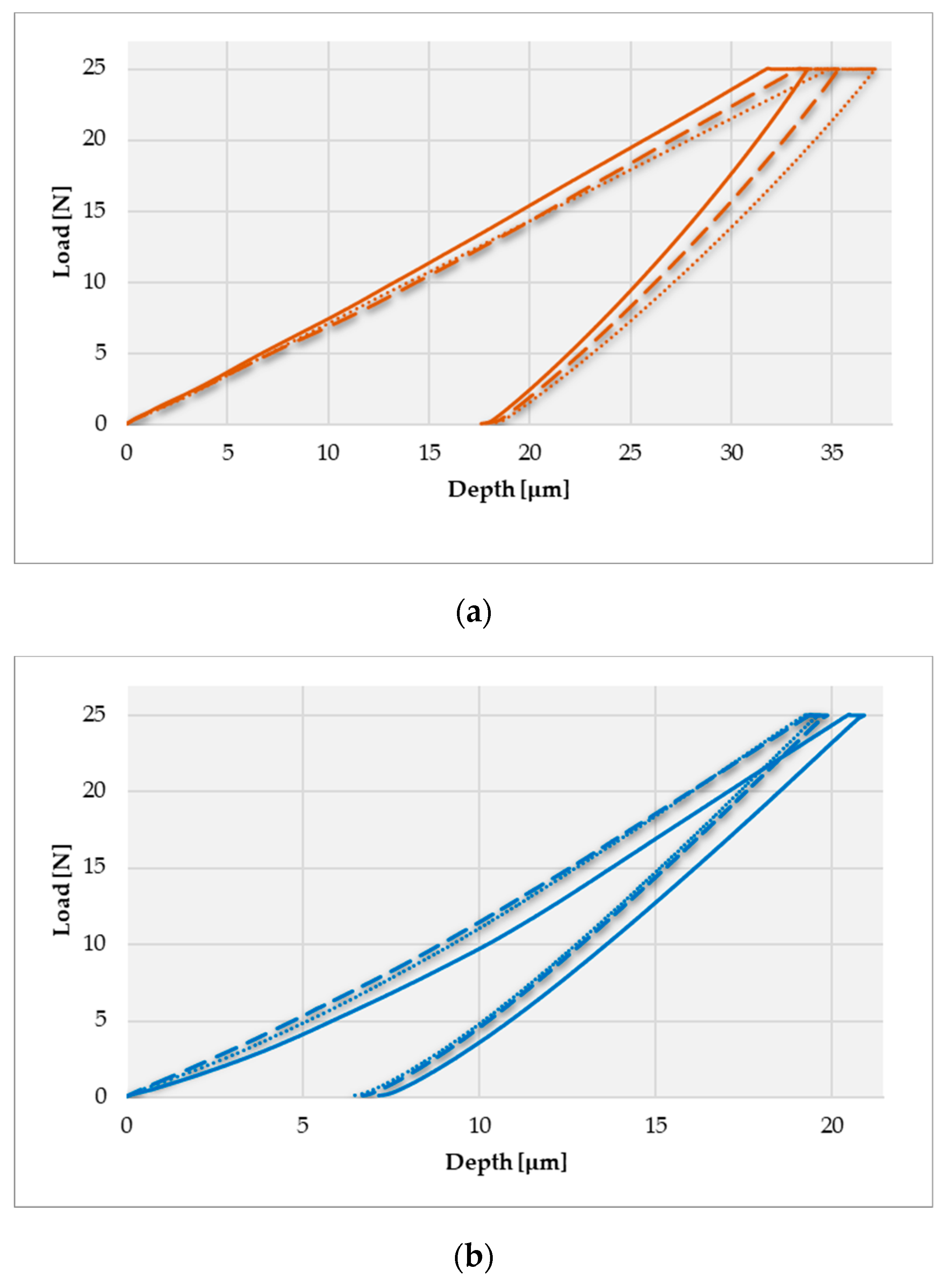
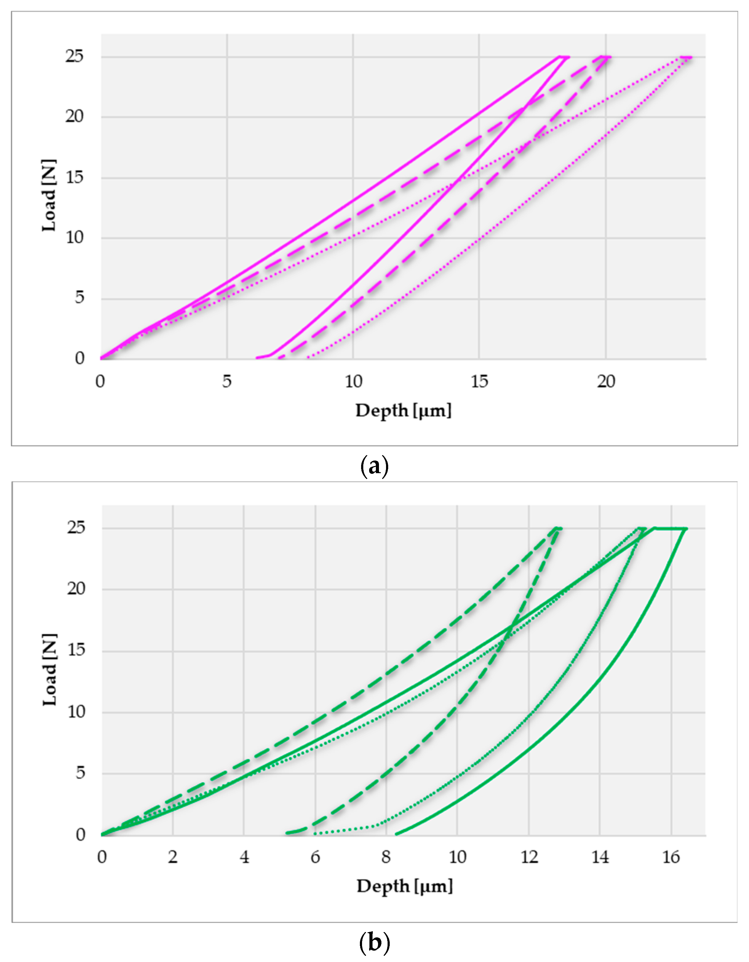
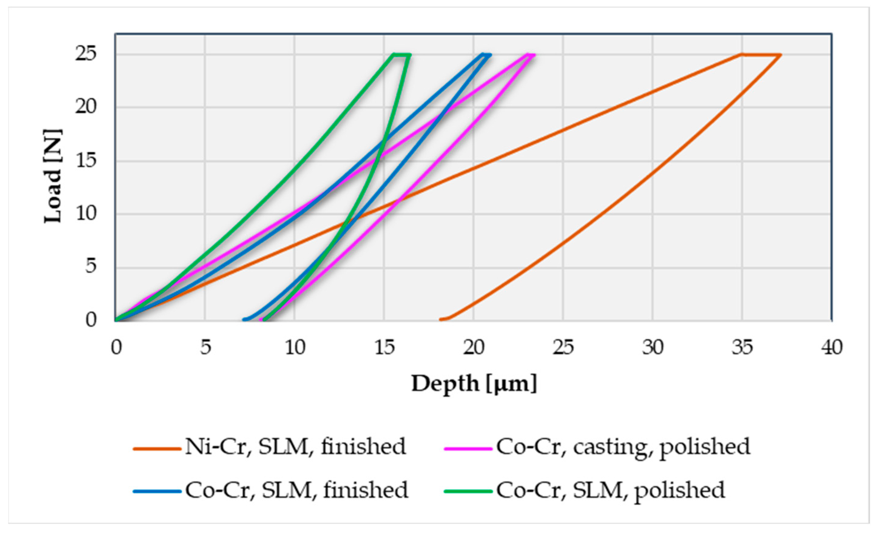
3.1. Results of the Mechanical Characteristics of Dental Prostheses Obtained after an Indentation Test
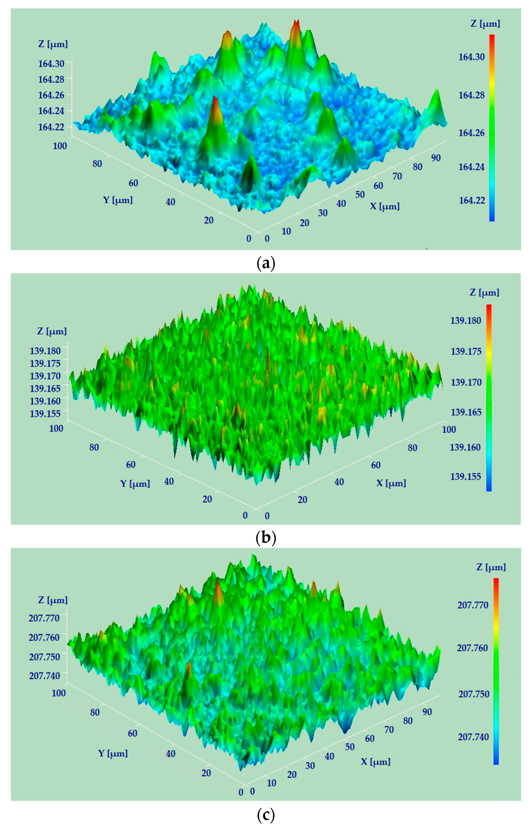
3.2. Microtopography and Zonal Nano-Roughness Results of Dental Prostheses Obtained by AFM
4. Discussions
4.1. Mechanical Characteristics
4.2. Microtopography and Zonal Nano-Roughness
5. Conclusions
- -
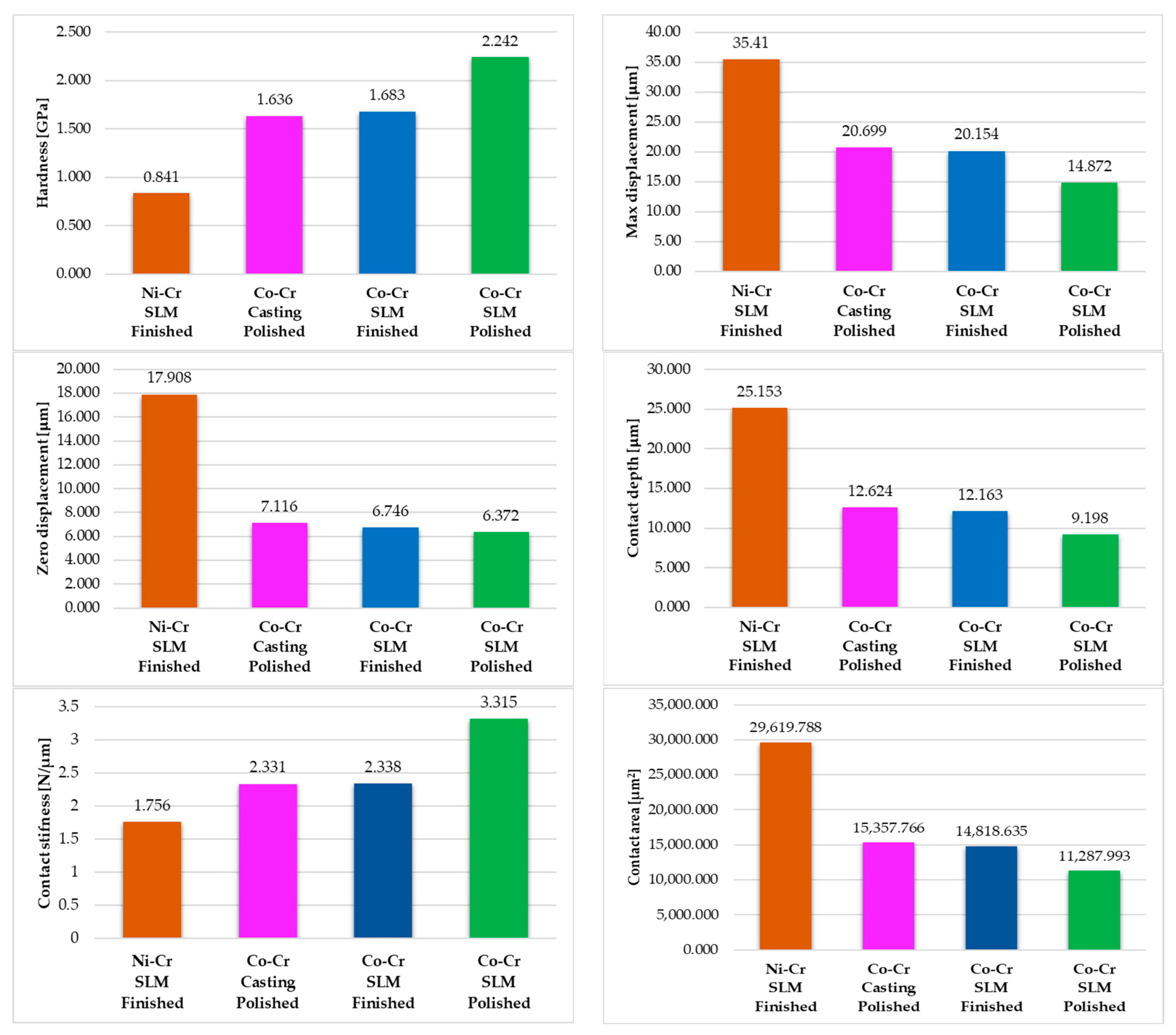
- Considering the same technology (SLM) and the same degree of finishing, compared to the Ni-Cr prosthesis, the Co-Cr one had a twice higher average indentation hardness and a contact stiffness over 33% higher. The Co-Cr prosthesis was also harder to deform than the Ni-Cr one.
- -
- Considering the same degree of finishing and almost the same material (Co-Cr alloy), the prosthesis realized via SLM has a 37% higher indentation hardness and more than 42% higher contact stiffness than the prosthesis obtained by casting. Also, the indentation deformations are much smaller in the case of the prosthesis made by SLM than in the case of the prosthesis obtained by casting.
- -
- The best mechanical properties and the greatest resistance to deformation after indentation tests were obtained in the case of the polished SLM dental prosthesis. The preliminarily finished SLM dental prosthesis has mechanical properties comparable to the polished one made by casting.
- -
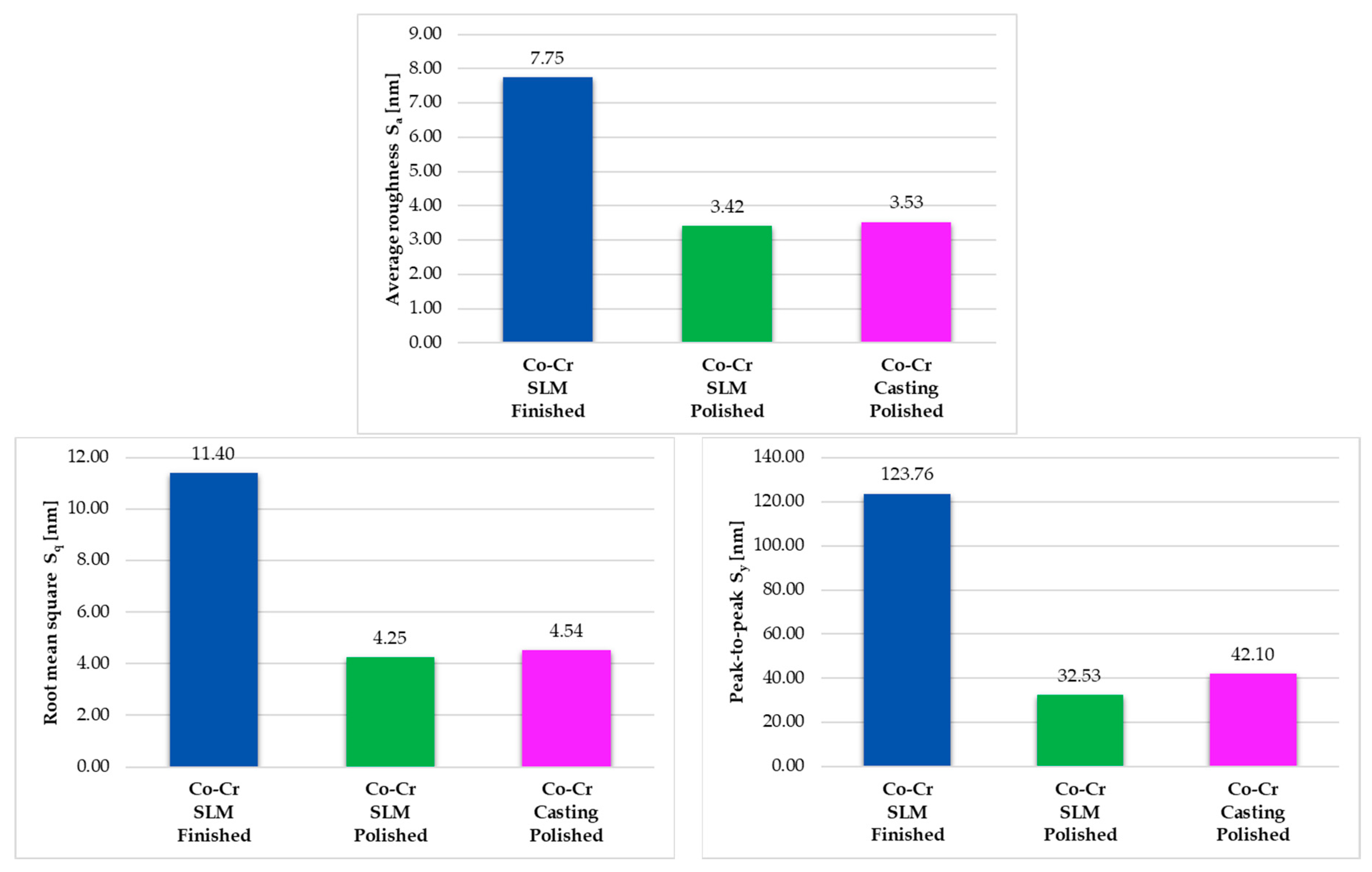
- Both in the case of the mechanical properties and especially in the case of the condition of the surfaces, the major impact that the post-processing operations of dental prostheses have on these characteristics was shown. After polishing the dental prosthesis made by SLM, a significantly higher average indentation hardness was obtained compared to the results obtained for the preliminarily finished SLM dental prosthesis (2.242 GPa compared to 1.683 GPa) with a greater contact stiffness (3.315 N/μm compared to 2.338 N/μm). Also, the polishing of the prosthesis led to an increase in resistance to deformation; for example, an average maximum displacement of 14.872 μm was obtained for the polished sample compared to an average maximum displacement of 20.154 μm for the preliminarily finished sample. The effects of polishing were even more evident for the average values determined for the microscale roughness parameters: in the case of the polished SLM dental prosthesis, the average roughness improved more than twice, the RMS parameter more than 2.5 times, and the distance between the extremities of the irregularities decreased almost 4 times compared to preliminarily finished SLM dental prosthesis.
- -
- The roughness parameters are not significantly influenced by the method of obtaining the dental prostheses after applying the same degree of post-processing. Obviously, the differences appear when moving to a higher degree of finishing.
- -
- Surface roughness plays a decisive role in durability and mechanical properties, but also in avoiding possible problems of biological nature; therefore, the use of appropriate post-processing operations for dental prostheses is very important.
Author Contributions
Funding
Institutional Review Board Statement
Informed Consent Statement
Data Availability Statement
Acknowledgments
Conflicts of Interest
References
- Moraru, E.; Dontu, O.; Petre, A.; Vaireanu, D.; Constantinescu, F.; Besnea, D. Some technological particularities on the execution of dental prostheses realized by selective laser deposition. J. Optoelectron. Adv. Mater. 2018, 20, 208–213. [Google Scholar]
- Moraru, E. Research on the Realization of Dental Prostheses by Selective Laser Deposition and Other Additive Technologies. Ph.D. Thesis, Politehnica University of Bucharest, Bucharest, Romania, 2021. (In Romanian). [Google Scholar]
- Singh, D.D.; Mahender, T.; Reddy, A.R. Powder bed fusion process: A brief review. Mater. Today Proc. 2021, 46, 350–355. [Google Scholar] [CrossRef]
- Lupone, F.; Padovano, E.; Casamento, F.; Badini, C. Process phenomena and material properties in selective laser sintering of polymers: A review. Materials 2021, 15, 183. [Google Scholar] [CrossRef]
- Nandy, J.; Sarangi, H.; Sahoo, S. A review on direct metal laser sintering: Process features and microstructure modeling. Lasers Manuf. Mater. Process. 2019, 6, 280–316. [Google Scholar] [CrossRef]
- Sefene, E.M. State-of-the-art of selective laser melting process: A comprehensive review. J. Manuf. Syst. 2022, 63, 250–274. [Google Scholar] [CrossRef]
- Sharma, S.K.; Singh, A.K.; Mishra, R.K.; Shukla, A.K.; Sharma, C. Processing Techniques, Microstructural and Mechanical Properties of Additive Manufactured 316L Stainless Steel. J. Inst. Eng. India Ser. D 2023, 1–14. [Google Scholar] [CrossRef]
- Wenext, DMLS vs SLM—What Is’ the Difference? Available online: https://www.wenext.com/blog/3D-Printing/dmls-vs-slm (accessed on 30 July 2023).
- Xometry, DMLS vs. SLM: Differences and Comparison. Available online: https://www.xometry.com/resources/3d-printing/dmls-vs-slm-3d-printing/ (accessed on 30 July 2023).
- Körner, C. Additive manufacturing of metallic components by selective electron beam melting—A review. Int. Mater. Rev. 2016, 61, 361–377. [Google Scholar] [CrossRef]
- Svetlizky, D.; Das, M.; Zheng, B.; Vyatskikh, A.L.; Bose, S.; Bandyopadhyay, A.; Schoenung, J.M.; Lavernia, E.J.; Eliaz, N. Directed energy deposition (DED) additive manufacturing: Physical characteristics, defects, challenges and applications. Mater. Today 2021, 49, 271–295. [Google Scholar] [CrossRef]
- Babuska, T.F.; Krick, B.A.; Susan, D.F.; Kustas, A.B. Comparison of powder bed fusion and directed energy deposition for tailoring mechanical properties of traditionally brittle alloys. Manuf. Lett. 2021, 28, 30–34. [Google Scholar] [CrossRef]
- Pesode, P.; Barve, S. Additive manufacturing of metallic biomaterials and its biocompatibility. Mater. Today Proc. 2022; in press. [Google Scholar] [CrossRef]
- Wu, M.; Dong, X.; Qu, Y.; Yan, J.; Li, N. Analysis of microstructure and fatigue of cast versus selective laser-melted dental Co-Cr alloy. J. Prosthet. Dent. 2022, 128, 218.e1–218.e7. [Google Scholar]
- Yun, C.S.; Hanawa, T.; Hong, M.H.; Min, B.K.; Kwon, T.Y. Biocompatibility of Ni–Cr alloys, with the same composition, prepared by two new digital manufacturing techniques. Mater. Lett. 2021, 305, 130761. [Google Scholar] [CrossRef]
- Gajera, H.; Shah, D.; Pancholi, N. Effect of SLM process parameters on hardness and microstructure of stainless steel 316 material. Mater. Today Proc. 2022, 50, 1653–1659. [Google Scholar]
- Özsoy, K. Examining mechanical properties of profiles manufactured aluminium extrusion dies using powder bed fusion. Measurement 2021, 177, 109266. [Google Scholar] [CrossRef]
- Korium, M.S.; Roozbahani, H.; Alizadeh, M.; Perepelkina, S.; Handroos, H. Direct metal laser sintering of precious metals for jewelry applications: Process parameter selection and microstructure analysis. IEEE Access 2021, 9, 126530–126540. [Google Scholar] [CrossRef]
- Enneti, R.K.; Morgan, R.; Atre, S.V. Effect of process parameters on the Selective Laser Melting (SLM) of tungsten. Int. J. Refract. Met. Hard Mater. 2018, 71, 315–319. [Google Scholar] [CrossRef]
- Al-Rubaie, K.S.; Melotti, S.; Rabelo, A.; Paiva, J.M.; Elbestawi, M.A.; Veldhuis, S.C. Machinability of SLM-produced Ti6Al4V titanium alloy parts. J. Manuf. Process. 2020, 57, 768–786. [Google Scholar] [CrossRef]
- Pilipović, A.; Brajlih, T.; Drstvenšek, I. Influence of processing parameters on tensile properties of SLS polymer product. Polymers 2018, 10, 1208. [Google Scholar] [CrossRef]
- Idriss, A.I.; Li, J.; Wang, Y.; Guo, Y.; Elfaki, E.A.; Adam, S.A. Selective laser sintering (SLS) and post-processing of prosopis chilensis/polyethersulfone composite (PCPC). Materials 2020, 13, 3034. [Google Scholar] [CrossRef]
- Wu, S.; Yang, L.; Wang, C.; Yan, C.; Shi, Y. Si/SiC ceramic lattices with a triply periodic minimal surface structure prepared by laser powder bed fusion. Addit. Manuf. 2022, 56, 102910. [Google Scholar] [CrossRef]
- Yap, C.Y.; Chua, C.K.; Dong, Z.L.; Liu, Z.H.; Zhang, D.Q.; Loh, L.E.; Sing, S.L. Review of selective laser melting: Materials and applications. Appl. Phys. Rev. 2015, 2, 041101. [Google Scholar] [CrossRef]
- Javaid, M.; Haleem, A. Current status and applications of additive manufacturing in dentistry: A literature-based review. J. Oral Biol. Craniofac. Res. 2019, 9, 179–185. [Google Scholar] [CrossRef] [PubMed]
- Aufa, A.N.; Hassan, M.Z.; Ismail, Z. Recent advances in Ti-6Al-4V additively manufactured by selective laser melting for biomedical implants: Prospect development. J. Alloys Compd. 2022, 896, 163072. [Google Scholar] [CrossRef]
- Gao, B.; Zhao, H.; Peng, L.; Sun, Z. A review of research progress in selective laser melting (SLM). Micromachines 2022, 14, 57. [Google Scholar] [CrossRef]
- Blakey-Milner, B.; Gradl, P.; Snedden, G.; Brooks, M.; Pitot, J.; Lopez, E.; Leary, M.; Berto, F.; Du Plessis, A. Metal additive manufacturing in aerospace: A review. Mater. Des. 2021, 209, 110008. [Google Scholar] [CrossRef]
- Charles, A.; Hofer, A.; Elkaseer, A.; Scholz, S.G. Additive Manufacturing in the Automotive Industry and the Potential for Driving the Green and Electric Transition. In Sustainable Design and Manufacturing; Scholz, S.G., Howlett, R.J., Setchi, R., Eds.; Smart Innovation, Systems and Technologies; Springer: Singapore, 2022; Volume 262. [Google Scholar]
- Zito, D.; Carlotto, A.; Loggi, A.; Sbornicchia, P.; Maggian, D.; Progold, S.A. Optimization of SLM technology main parameters in the production of gold and platinum jewelry. In Proceedings of the Santa Fe Symposium on Jewelry Manufacturing Technology, Albuquerque, NM, USA, 18–21 May 2014; Met-Chem Research. Volume 47, pp. 439–470. [Google Scholar]
- Salmi, M. Additive manufacturing processes in medical applications. Materials 2021, 14, 191. [Google Scholar] [CrossRef]
- Cortis, G.; Mileti, I.; Nalli, F.; Palermo, E.; Cortese, L. Additive manufacturing structural redesign of hip prostheses for stress-shielding reduction and improved functionality and safety. Mech. Mater. 2022, 165, 104173. [Google Scholar] [CrossRef]
- Ni, J.; Liu, F.; Yang, G.; Lee, G.H.; Chung, S.M.; Lee, I.S.; Chen, C. 3D-printed Ti6Al4V femoral component of knee: Improvements in wear and biological properties by AIP TiN and TiCrN coating. J. Mater. Res. Technol. 2021, 14, 2322–2332. [Google Scholar] [CrossRef]
- Sharma, N.; Ostas, D.; Rotar, H.; Brantner, P.; Thieringer, F.M. Design and additive manufacturing of a biomimetic customized cranial implant based on voronoi diagram. Front. Physiol. 2021, 12, 647923. [Google Scholar] [CrossRef]
- Yang, H.J.; Oh, J.H. Reconstruction of Mandibular Contour Defect Using Patient-Specific Titanium Implant Manufactured by Selective Laser Melting Method. J. Craniofac. Surg. 2022, 33, 2055. [Google Scholar] [CrossRef]
- Nahata, S.; Ozdoganlar, O.B. Feasibility of metal additive manufacturing for fabricating custom surgical instrumentation for hip and knee implants. Procedia Manuf. 2019, 34, 772–779. [Google Scholar] [CrossRef]
- Munir, K.; Biesiekierski, A.; Wen, C.; Li, Y. Powder metallurgy in manufacturing of medical devices. In Metallic Biomaterials Processing and Medical Device Manufacturing; Woodhead Publishing: Sawston, UK, 2020; pp. 159–190. [Google Scholar]
- Oliveira, T.T.; Reis, A.C. Fabrication of dental implants by the additive manufacturing method: A systematic review. J. Prosthet. Dent. 2019, 122, 270–274. [Google Scholar] [CrossRef]
- SLM Solutions, SLM Medical and Dental Applications. Available online: https://www.slm-solutions.com/industries/healthcare/ (accessed on 1 August 2023).
- Lesyk, D.; Martinez, S.; Mordyuk, B.; Dzhemelinskyi, V.; Lamikiz, A. Surface Finishing of Complexly Shaped Parts Fabricated by Selective Laser Melting. In Advanced Manufacturing Processes; Tonkonogyi, V., Ivanov, V., Trojanowska, J., Oborskyi, G., Edl, M., Kuric, I., Pavlenko, I., Dasic, P., Eds.; Lecture Notes in Mechanical Engineering; Springer: Cham, Switzerland, 2019. [Google Scholar]
- Boban, J.; Ahmed, A.; Jithinraj, E.K.; Rahman, M.A.; Rahman, M. Polishing of additive manufactured metallic components: Retrospect on existing methods and future prospects. Int. J. Adv. Manuf. Technol. 2022, 121, 83–125. [Google Scholar] [CrossRef]
- Baicheng, Z.; Xiaohua, L.; Jiaming, B.; Junfeng, G.; Pan, W.; Chen-nan, S.; Muiling, N.; Guojun, Q.; Jun, W. Study of selective laser melting (SLM) Inconel 718 part surface improvement by electrochemical polishing. Mater. Des. 2017, 116, 531–537. [Google Scholar] [CrossRef]
- Rashid, H. The effect of surface roughness on ceramics used in dentistry: A review of literature. Eur. J. Dent. 2014, 8, 571–579. [Google Scholar] [CrossRef] [PubMed]
- Velioglu, N.; Akova, T.; Ozkomur, A. Effects of hard thin-film coatings on adhesion of early colonizer bacteria over titanium surfaces. Implant Dent. 2016, 25, 114–121. [Google Scholar] [CrossRef]
- Øilo, M.; Nesse, H.; Lundberg, O.J.; Gjerdet, N.R. Mechanical properties of cobalt-chromium 3-unit fixed dental prostheses fabricated by casting, milling, and additive manufacturing. J. Prosthet. Dent. 2018, 120, 156-e1. [Google Scholar] [CrossRef] [PubMed]
- Zhou, Y.; Li, N.; Yan, J.; Zeng, Q. Comparative analysis of the microstructures and mechanical properties of Co-Cr dental alloys fabricated by different methods. J. Prosthet. Dent. 2018, 120, 617–623. [Google Scholar] [CrossRef]
- Han, X.; Sawada, T.; Schille, C.; Schweizer, E.; Scheideler, L.; Geis-Gerstorfer, J.; Rupp, F.; Spintzyk, S. Comparative analysis of mechanical properties and metal-ceramic bond strength of Co-Cr dental alloy fabricated by different manufacturing processes. Materials 2018, 11, 1801. [Google Scholar] [CrossRef]
- Baciu, E.R.; Cimpoeșu, R.; Vițalariu, A.; Baciu, C.; Cimpoeșu, N.; Sodor, A.; Zegan, G.; Murariu, A. Surface analysis of 3D (SLM) Co–Cr–W dental metallic materials. Appl. Sci. 2020, 11, 255. [Google Scholar] [CrossRef]
- Shu, T.; Zhang, Y.; Sun, G.; Pan, Y.; He, G.; Cheng, Y.; Li, A.; Pei, D. Enhanced osseointegration by the hierarchical micro-nano topography on selective laser melting Ti-6Al-4V dental implants. Front. Bioeng. Biotechnol. 2021, 8, 621601. [Google Scholar] [CrossRef]
- Moraru, E.; Dontu, G.O.; Cananau, S.; Stanescu, V.A. Approaches and Processing Technologies for Medical Devices: Considerations from Micro- and Macroscale Perspectives. In International Conference on Reliable Systems Engineering (ICoRSE)—2023; Cioboată, D.D., Ed.; Lecture Notes in Networks and Systems; Springer: Cham, Switzerland, 2023; Volume 762. [Google Scholar]
- Tarcolea, M.; Hancu, V.; Miculescu, F.; Smatrea, O.; Coman, C.; Comaneanu, R.M.; Ormenisan, A. Research on microstructural and chemical inhomogeneity in cast metal crowns made of CoCrMoW alloy. Rev. Chim. 2015, 66, 1143. [Google Scholar]
- Branzei, M.; Pencea, I.; Matei, A.A.; Sfat, C.E.; Antoniac, I.V.; Turcu, R.N.; Manoliu, V. Influence of high temperature exposure on the adhesion of a micro-composite refractory enamel to a Ni–18Cr–12W superalloy. J. Adhes. Sci. Technol. 2017, 31, 2555–2570. [Google Scholar] [CrossRef]
- ISO 14577-1:2015; Metallic Materials—Instrumented Indentation Test for Hardness and Materials Parameters—Part 1: Test Method. ISO: Geneve, Switzerland, 2015.
- Xia, F.; Youcef-Toumi, K. Advanced Atomic Force Microscopy Modes for Biomedical Research. Biosensors 2022, 12, 1116. [Google Scholar] [CrossRef] [PubMed]
- Badita, L.L.; Gheorghe, G.I. Orthopaedic prosthetic systems topographically characterized at nanometric scale. Adv. Mater. Res. 2014, 837, 675–681. [Google Scholar] [CrossRef]
- Evident Olympus, Surface Roughness Measurement. Areal Method (Areal Roughness) Parameters. Available online: https://www.olympus-ims.com/en/metrology/surface-roughness-measurement-portal/ (accessed on 31 August 2023).
- Keyence, Area Roughness Parameter. Available online: https://www.keyence.com/ss/products/microscope/roughness/surface/parameters.jsp (accessed on 31 August 2023).


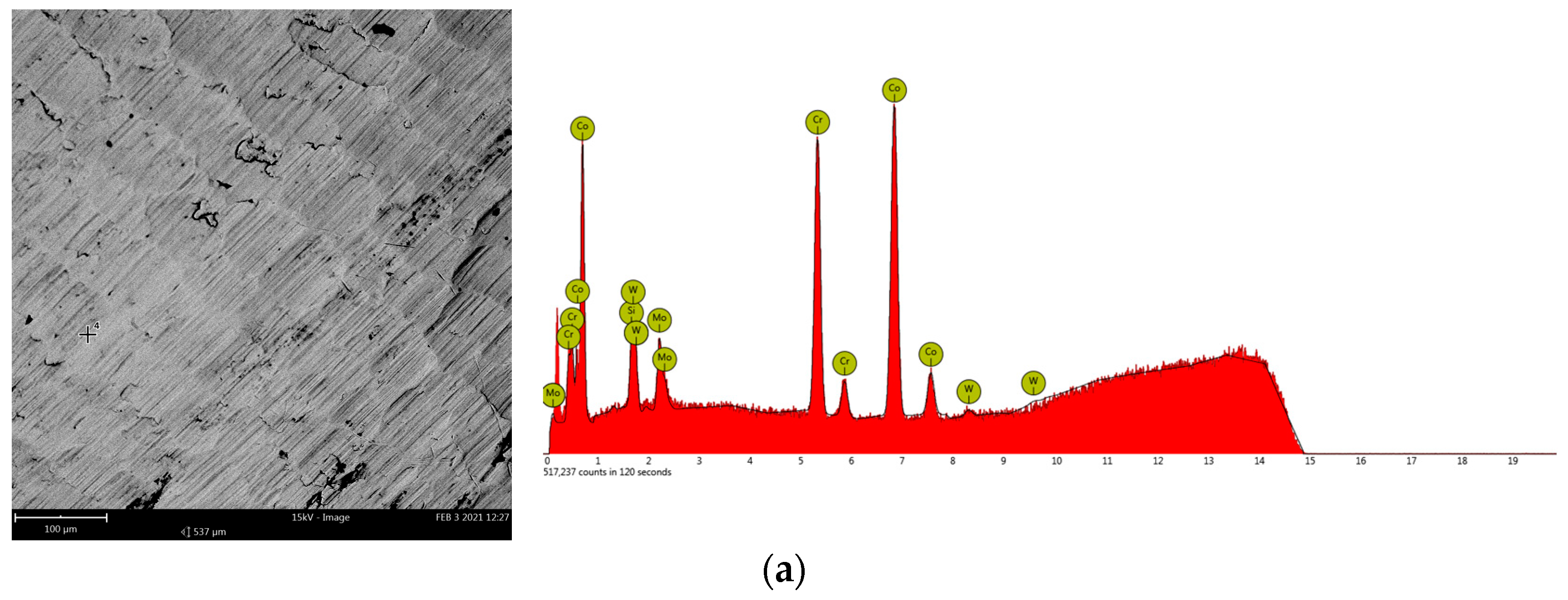
| Co | Cr | W | Mo | Si | |
|---|---|---|---|---|---|
| at% | 54.49 ± 1.44 | 26.15 ± 0.49 | 9.29 ± 1.54 | 4.86 ± 0.33 | 5.21 ± 0.44 |
| wt% | 46.65 ± 2.57 | 19.75 ± 0.92 | 24.71 ± 3.45 | 6.76 ± 0.40 | 2.13 ± 0.20 |
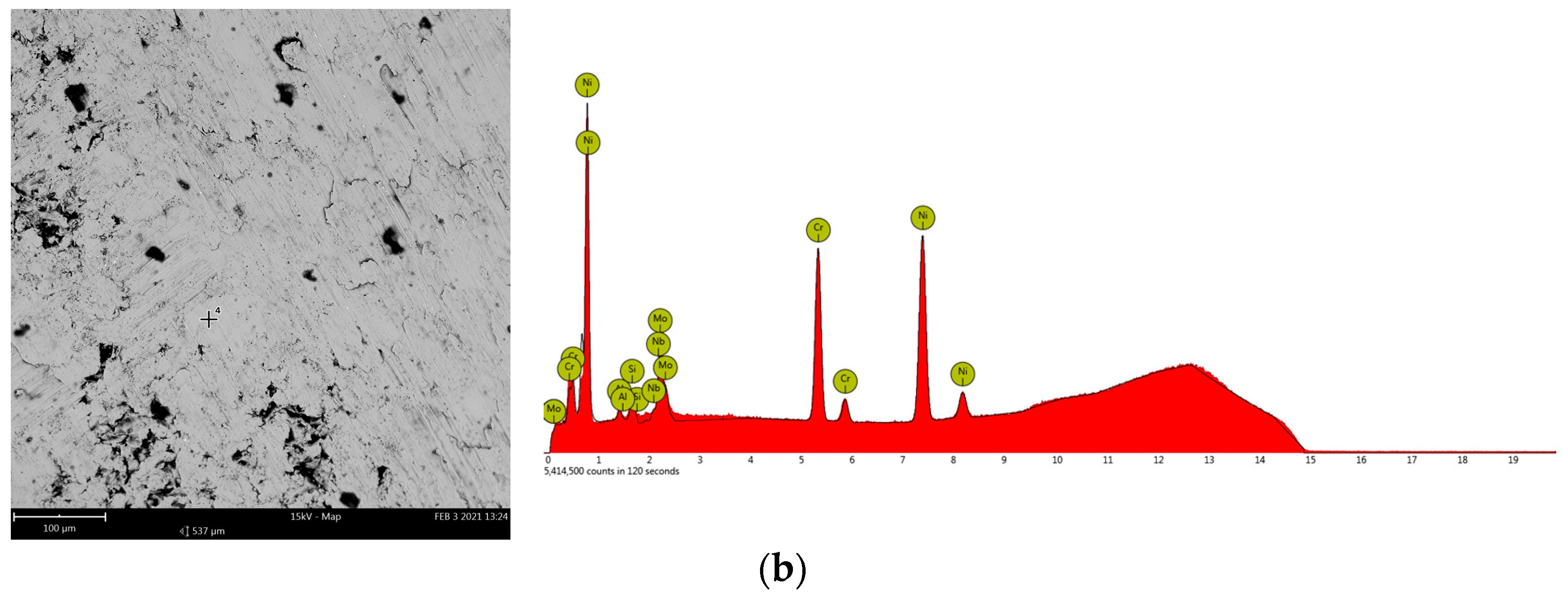
| Ni | Cr | Mo | Si | Nb | Al | |
|---|---|---|---|---|---|---|
| at% | 63.90 ± 1.76 | 25.74 ± 0.66 | 6.30 ± 1.15 | 2.61 ± 0.71 | 0.82 ± 0.24 | 0.63 ± 0.44 |
| wt% | 64.02 ± 2.11 | 22.85 ± 0.63 | 10.30 ± 1.85 | 1.25 ± 0.33 | 1.29 ± 0.38 | 0.29 ± 0.20 |
| Property | Material | Ni-Cr | Co-Cr | Co-Cr | Co-Cr |
|---|---|---|---|---|---|
| Method | SLM | Casting | SLM | SLM | |
| Post-Process | Finished | Polished | Finished | Polished | |
25/40/30/40 | 1 | 0.866 | 1.824 | 1.607 | 1.892 |
| 2 | 0.843 | 1.648 | 1.7 | 2.581 | |
| 3 | 0.815 | 1.437 | 1.741 | 2.252 | |
| Average | 0.841 | 1.636 | 1.683 | 2.242 | |
| Max. displ. [μm] | 1 | 33.789 | 18.542 | 20.921 | 16.433 |
| 2 | 35.316 | 20.177 | 19.875 | 12.906 | |
| 3 | 37.13 | 23.378 | 19.665 | 15.278 | |
| Average | 35.41 | 20.699 | 20.154 | 14.872 | |
| Zero displ. [μm] | 1 | 17.759 | 6.193 | 7.147 | 8.279 |
| 2 | 17.828 | 7.077 | 6.682 | 4.953 | |
| 3 | 18.138 | 8.077 | 6.41 | 5.883 | |
| Average | 17.908 | 7.116 | 6.746 | 6.372 | |
| Contact depth [μm] | 1 | 24.369 | 11.177 | 12.74 | 10.763 |
| 2 | 25.079 | 12.405 | 12.02 | 7.829 | |
| 3 | 26.012 | 14.289 | 11.728 | 9.001 | |
| Average | 25.153 | 12.624 | 12.163 | 9.198 | |
| Contact stiffness [N/μm] | 1 | 1.903 | 2.536 | 2.283 | 3.293 |
| 2 | 1.752 | 2.403 | 2.378 | 3.678 | |
| 3 | 1.613 | 2.053 | 2.353 | 2.975 | |
| Average | 1.756 | 2.331 | 2.338 | 3.315 | |
| Contact area [μm2] | 1 | 28,757.482 | 13,653.115 | 15,500.097 | 13,161.51 |
| 2 | 29,539.568 | 15,105.065 | 14,650.44 | 9646.015 | |
| 3 | 30,562.315 | 17,315.117 | 14,305.369 | 11,056.454 | |
| Average | 29,619.788 | 15,357.766 | 14,818.635 | 11,287.993 |
| Parameter | Material | Co-Cr | Co-Cr | Co-Cr |
|---|---|---|---|---|
| Method | SLM | SLM | Casting | |
| Post-Process | Finished | Polished | Polished | |
| Average roughness Sa (nm) | 1 | 6.81 | 4.53 | 3.37 |
| 2 | 9.80 | 2.78 | 3.72 | |
| 3 | 6.64 | 2.95 | 3.50 | |
| Average | 7.75 | 3.42 | 3.53 | |
| Root-mean-square Sq (nm) | 1 | 9.68 | 5.62 | 4.30 |
| 2 | 15.06 | 3.46 | 4.81 | |
| 3 | 9.47 | 3.67 | 4.50 | |
| Average | 11.40 | 4.25 | 4.54 | |
| Peak-to-peak Sy (nm) | 1 | 94.03 | 38.09 | 38.32 |
| 2 | 183.23 | 30.94 | 45.41 | |
| 3 | 94.03 | 28.56 | 42.57 | |
| Average | 123.76 | 32.53 | 42.10 |
Disclaimer/Publisher’s Note: The statements, opinions and data contained in all publications are solely those of the individual author(s) and contributor(s) and not of MDPI and/or the editor(s). MDPI and/or the editor(s) disclaim responsibility for any injury to people or property resulting from any ideas, methods, instructions or products referred to in the content. |
© 2023 by the authors. Licensee MDPI, Basel, Switzerland. This article is an open access article distributed under the terms and conditions of the Creative Commons Attribution (CC BY) license (https://creativecommons.org/licenses/by/4.0/).
Share and Cite
Moraru, E.; Stoica, A.-M.; Donțu, O.; Cănănău, S.; Stoica, N.-A.; Constantin, V.; Cioboată, D.-D.; Bădiță-Voicu, L.-L. Mechanical and Surface Characteristics of Selective Laser Melting-Manufactured Dental Prostheses in Different Processing Stages. Materials 2023, 16, 6141. https://doi.org/10.3390/ma16186141
Moraru E, Stoica A-M, Donțu O, Cănănău S, Stoica N-A, Constantin V, Cioboată D-D, Bădiță-Voicu L-L. Mechanical and Surface Characteristics of Selective Laser Melting-Manufactured Dental Prostheses in Different Processing Stages. Materials. 2023; 16(18):6141. https://doi.org/10.3390/ma16186141
Chicago/Turabian StyleMoraru, Edgar, Alina-Maria Stoica, Octavian Donțu, Sorin Cănănău, Nicolae-Alexandru Stoica, Victor Constantin, Daniela-Doina Cioboată, and Liliana-Laura Bădiță-Voicu. 2023. "Mechanical and Surface Characteristics of Selective Laser Melting-Manufactured Dental Prostheses in Different Processing Stages" Materials 16, no. 18: 6141. https://doi.org/10.3390/ma16186141