
Microstructural Evolution, Mechanical Properties and Tribological Behavior of B4C-Reinforced Ti In Situ Composites Produced by Laser Powder Bed Fusion


 and
and 
Abstract
:1. Introduction
2. Experiments
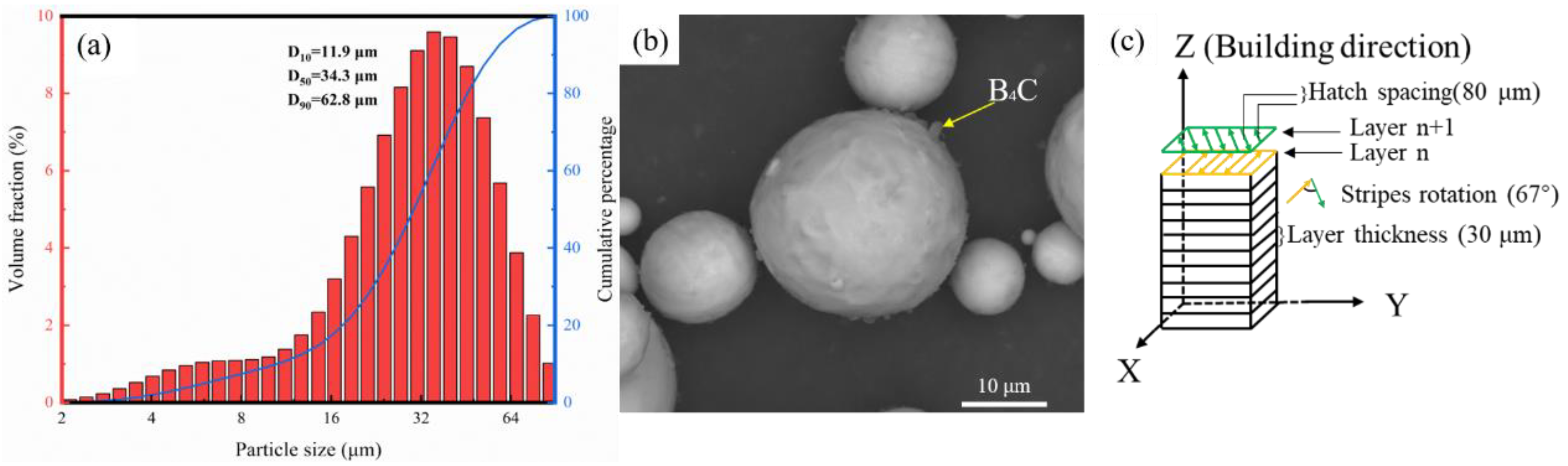
2.1. Powder Preparation
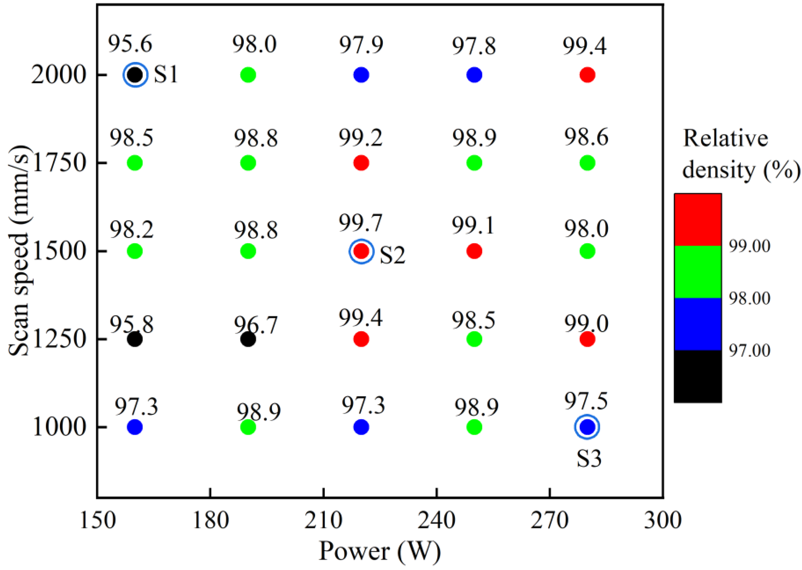
2.2. LPBF Process
2.3. Microstructural Characterization
2.4. Mechanical and Tribological Tests
3. Results
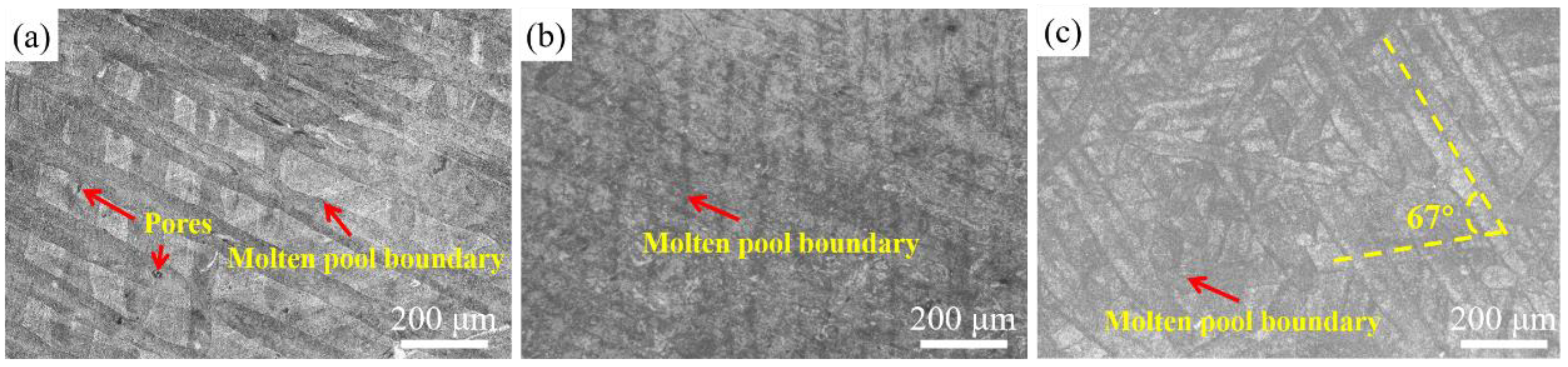
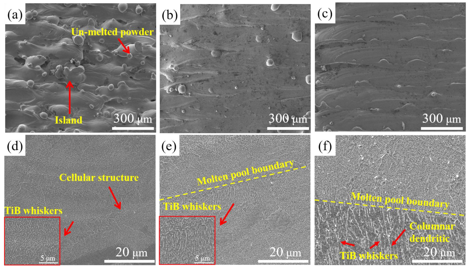
3.1. Microstructure
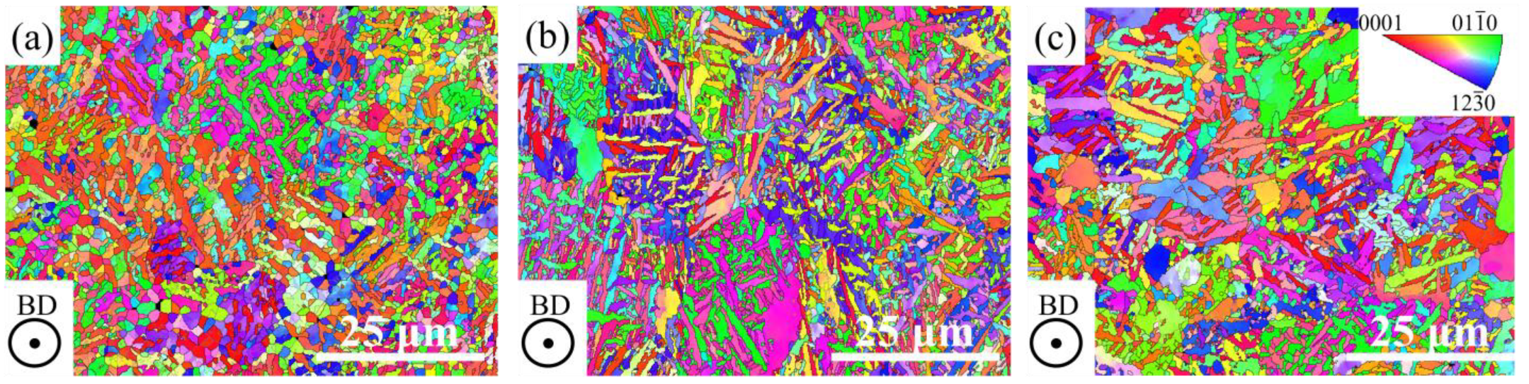
3.2. EBSD Characterization
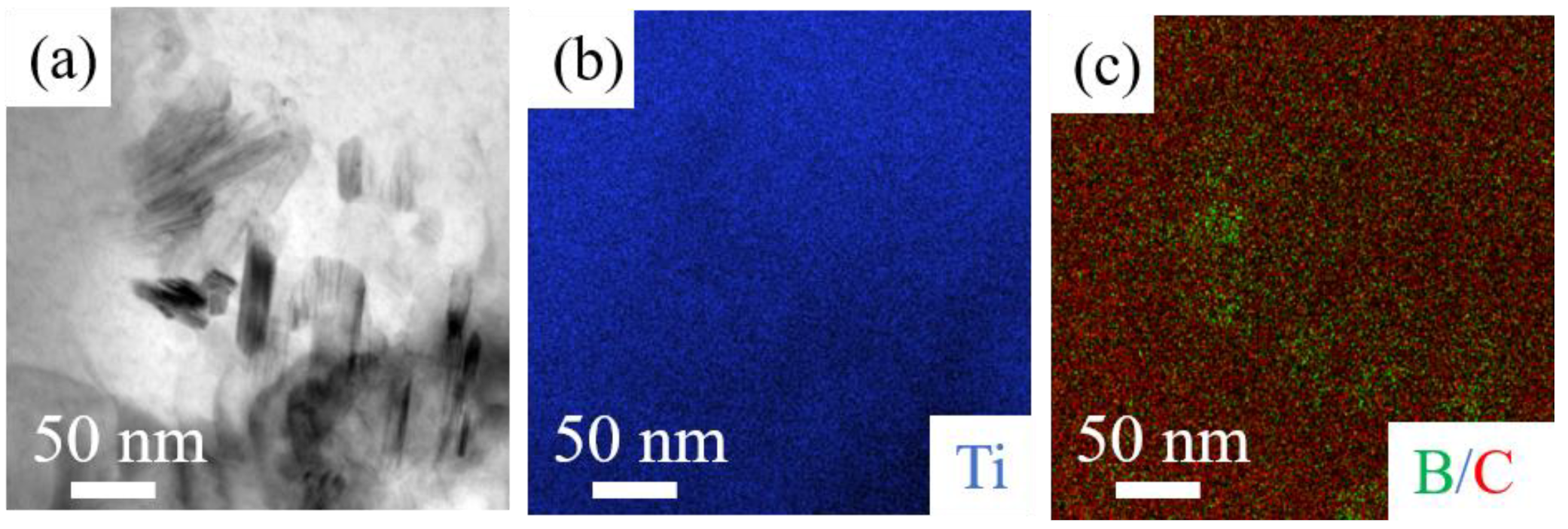
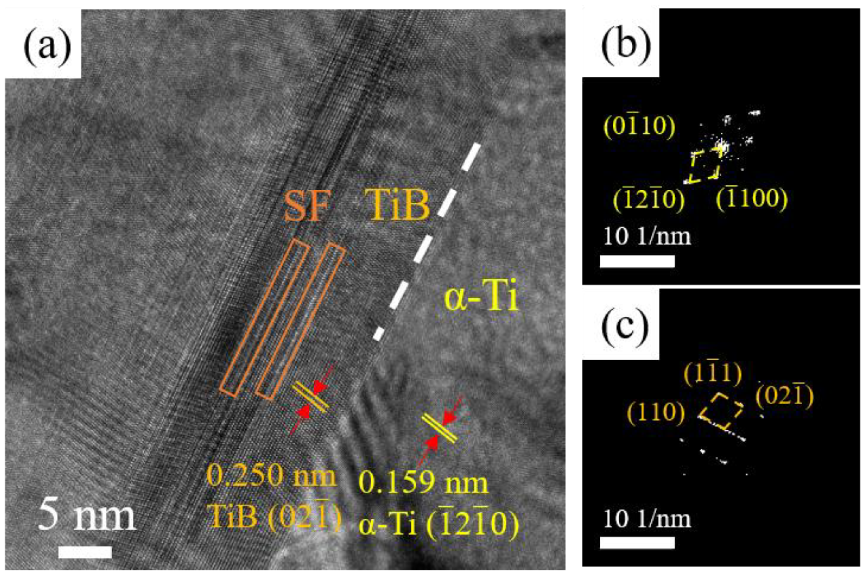
3.3. TEM Analysis
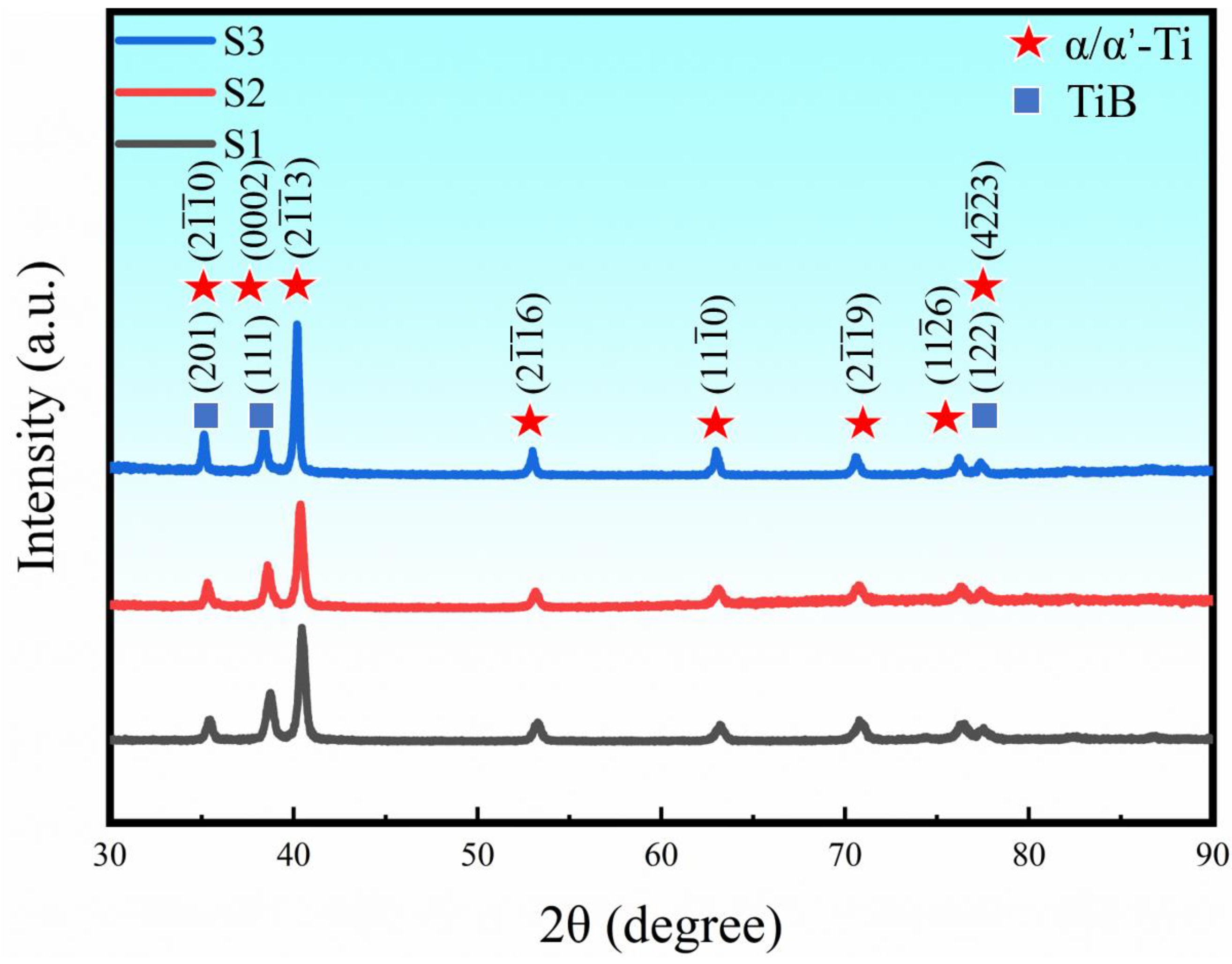
3.4. Phase Identification
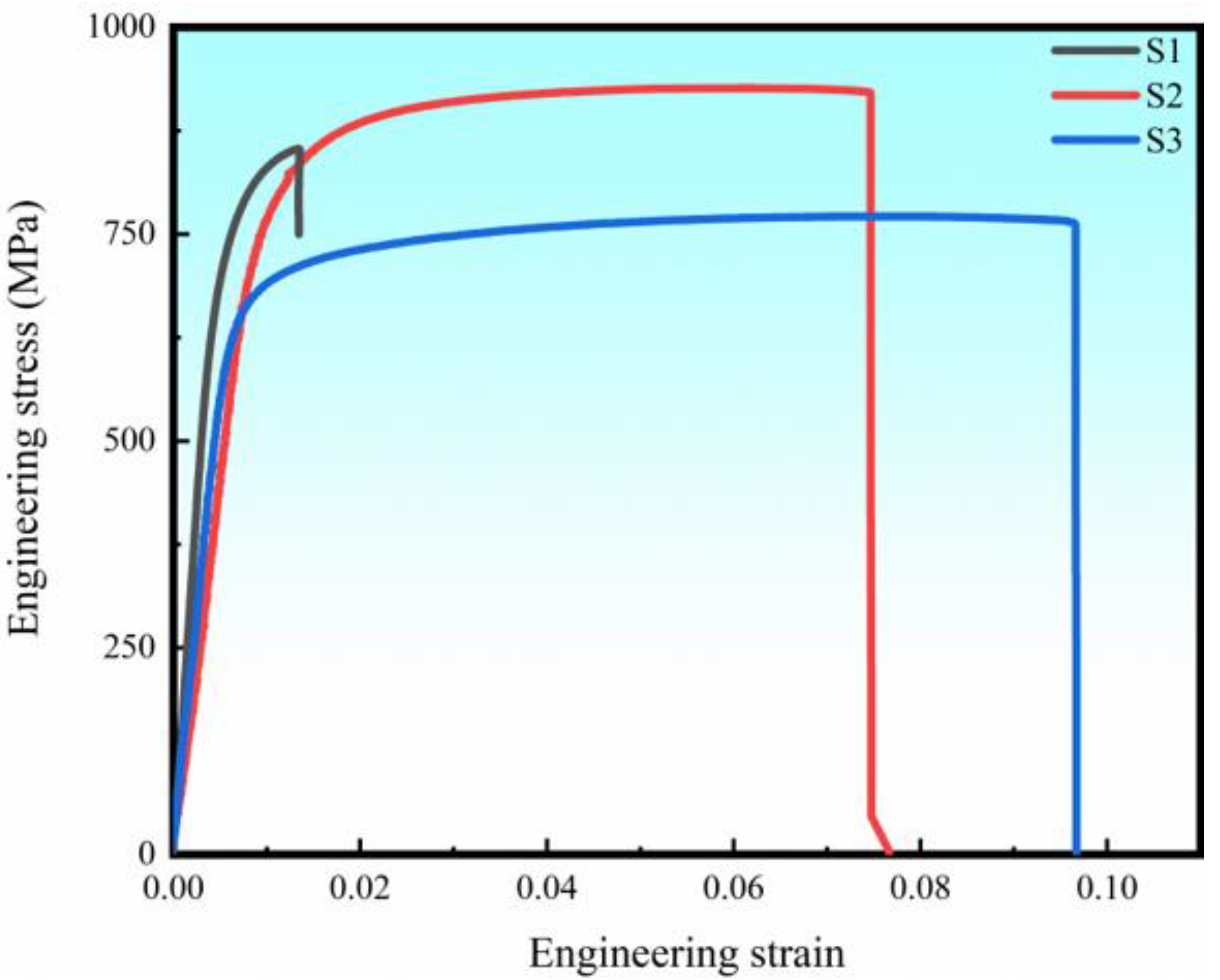
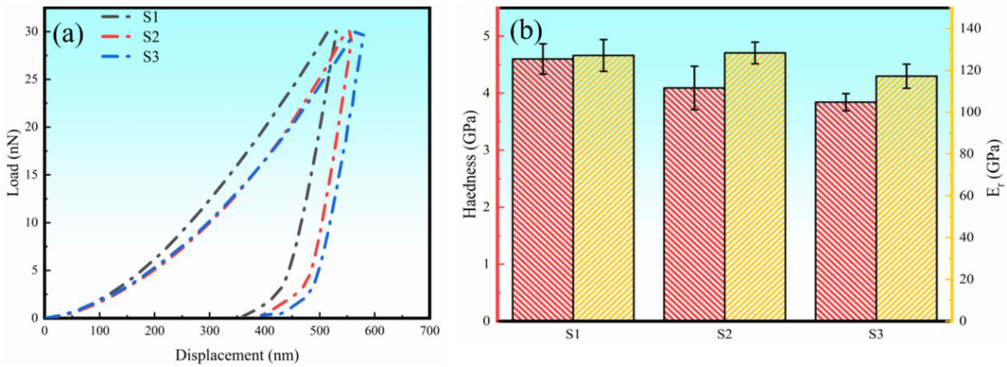
3.5. Mechanical Properties
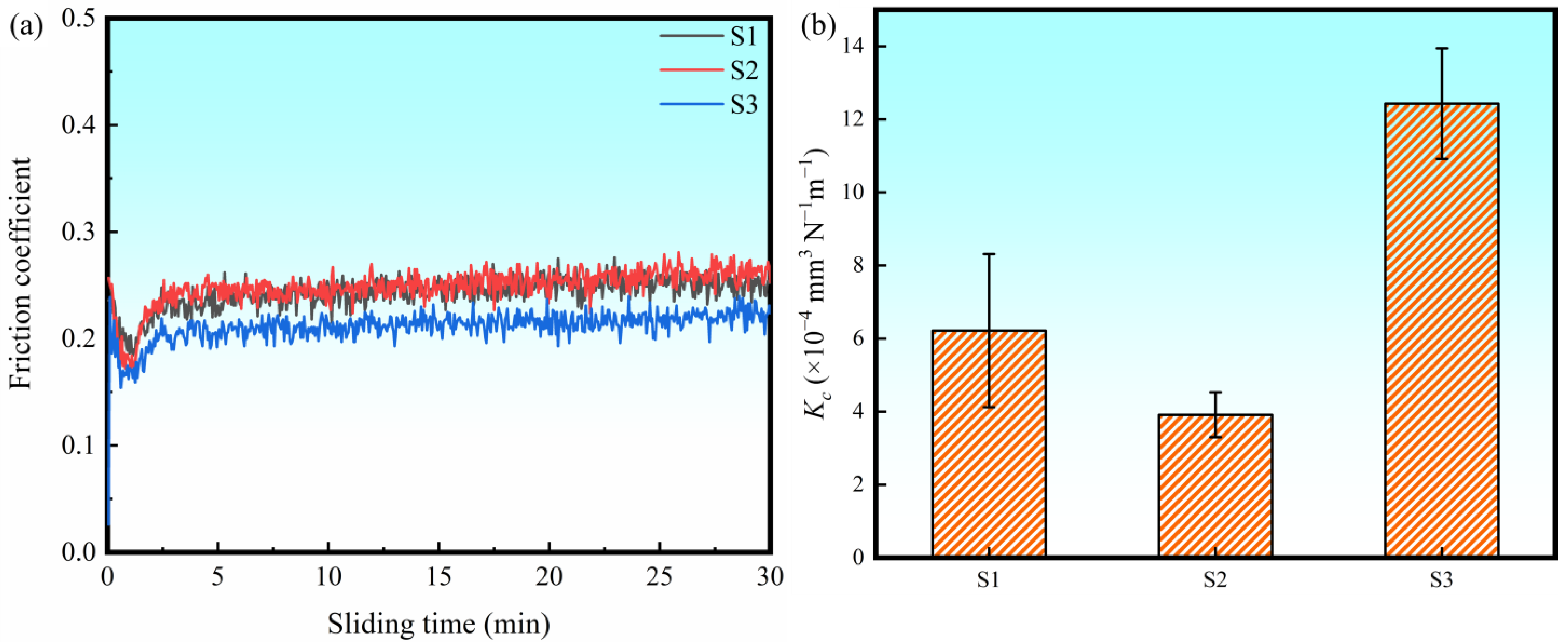
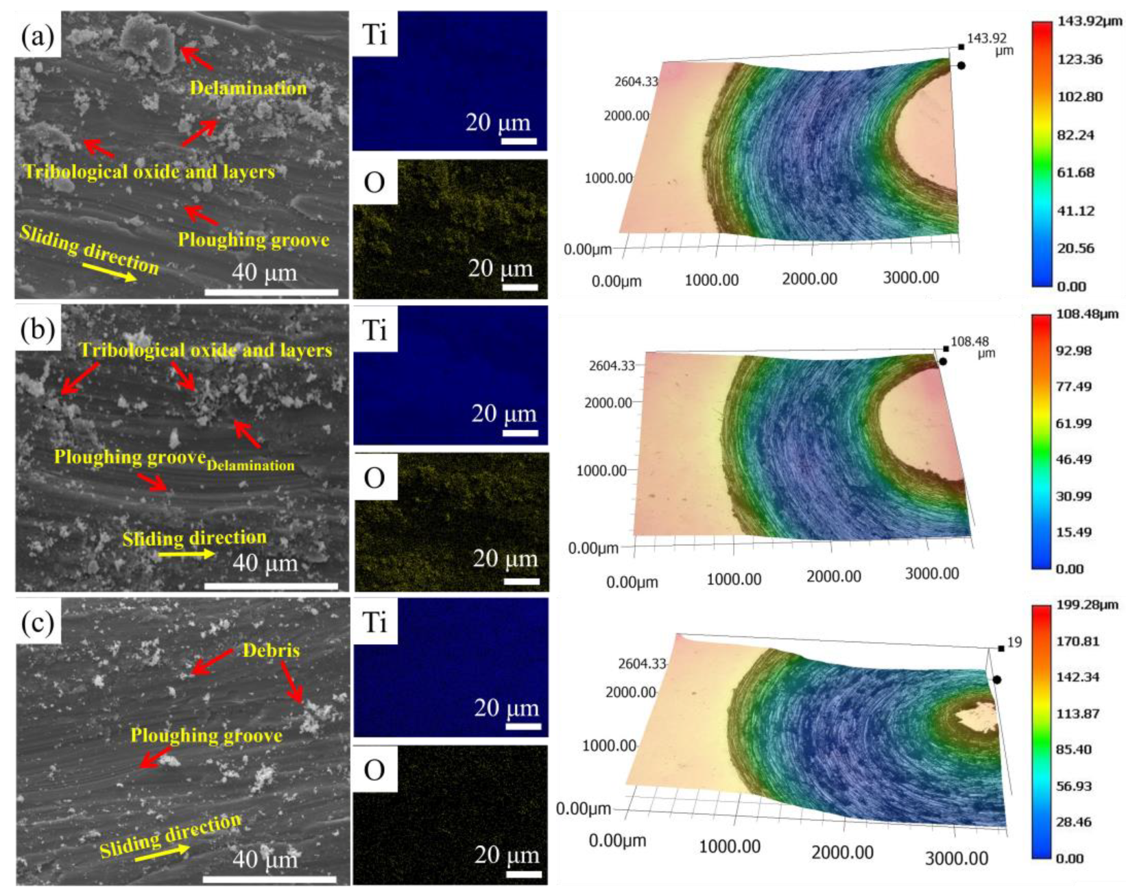
3.6. Tribological Behavior
4. Discussion
4.1. Microstructural Evolution
4.2. Mechanical Properties Analysis
4.3. Tribological Behavior Analysis
5. Conclusions
Author Contributions
Funding
Institutional Review Board Statement
Informed Consent Statement
Data Availability Statement
Acknowledgments
Conflicts of Interest
References
- Zhang, J.; Song, B.; Cai, C.; Zhang, L.; Shi, Y. Tailorable microstructure and mechanical properties of selective laser melted TiB/Ti–6Al–4V composite by heat treatment. Adv. Powder Mater. 2022, 1, 100010. [Google Scholar] [CrossRef]
- Zhang, Z.; Chen, J.; He, G.; Yang, G. Fatigue and Mechanical Behavior of Ti-6Al-4V Alloy with CrN and TiN Coating Deposited by Magnetic Filtered Cathodic Vacuum Arc Process. Coatings 2019, 9, 689. [Google Scholar] [CrossRef] [Green Version]
- Ali, T.; Wang, L.; Cheng, X.; Gu, D.; Zhou, Z.; Min, X. The effect of TiC on microstructure and mechanical properties of Ti-5553 beta phase titanium alloy. Mater. Des. 2022, 214, 110395. [Google Scholar] [CrossRef]
- Zhang, W. A review of tribological properties for boron carbide ceramics. Prog. Mater. Sci. 2021, 116, 100718. [Google Scholar] [CrossRef]
- Chand, S.; Chandrasekhar, P.; Sarangi, R.; Nayak, R. Influence of B4C particles on processing and strengthening mechanisms in aluminum metal matrix composites-a review. Mater. Today Proc. 2019, 18, 5356–5363. [Google Scholar] [CrossRef]
- Soy, U.; Demir, A.; Findik, F. Friction and wear behaviors of Al-SiC-B4C composites produced by pressure infiltration method. Ind. Lubr. Tribol. 2011, 63, 387–393. [Google Scholar] [CrossRef]
- Sousa, L.; Alves, A.; Guedes, A.; Toptan, F. Corrosion and tribocorrosion behaviour of Ti-B4C composites processed by conventional sintering and hot-pressing technique. J. Alloys Compd. 2021, 885, 161109. [Google Scholar] [CrossRef]
- Han, C.; Babicheva, R.; Chua, J.D.Q.; Ramamurty, U.; Tor, S.B.; Sun, C.-N.; Zhou, K. Microstructure and mechanical properties of (TiB+ TiC)/Ti composites fabricated in situ via selective laser melting of Ti and B4C powders. Addit. Manuf. 2020, 36, 101466. [Google Scholar] [CrossRef]
- Ren, Y.; Wu, H.; Agbedor, S.-O.; Lu, Y.; Zhang, Y.; Fang, Q.; Li, J.; Tian, Y.; Baker, I. Microstructure, mechanical and tribological properties of a Ti-5Cu alloy and a B4C/Ti-5Cu in situ composite fabricated by laser powder bed fusion. Mater. Charact. 2022, 192, 112217. [Google Scholar] [CrossRef]
- Zhang, Z.; Qin, J.; Zhang, Z.; Chen, Y.; Lu, W.; Zhang, D. Microstructure effect on mechanical properties of in situ synthesized titanium matrix composites reinforced with TiB and La2O3. Mater. Lett. 2010, 64, 361–363. [Google Scholar] [CrossRef]
- Yu, H.L.; Zhang, W.; Wang, H.M.; Ji, X.C.; Song, Z.Y.; Li, X.Y.; Xu, B.S. In-situ synthesis of TiC/Ti composite coating by high frequency induction cladding. J. Alloys Compd. 2017, 701, 244–255. [Google Scholar] [CrossRef] [Green Version]
- Li, S.; Kondoh, K.; Imai, H.; Chen, B.; Jia, L.; Umeda, J.; Fu, Y. Strengthening behavior of in situ-synthesized (TiC–TiB)/Ti composites by powder metallurgy and hot extrusion. Mater. Des. 2016, 95, 127–132. [Google Scholar] [CrossRef]
- Zhang, M.; Yuan, T.; Li, R. Effect of spark plasma sintering on microstructure and friction characteristics of boron carbide. J. Micromechanics Mol. Phys. 2018, 3, 1750014. [Google Scholar] [CrossRef]
- Sabahi Namini, A.; Delbari, S.A.; Nayebi, B.; Shahedi Asl, M.; Parvizi, S. Effect of B4C content on sintering behavior, microstructure and mechanical properties of Ti-based composites fabricated via spark plasma sintering. Mater. Chem. Phys. 2020, 251, 123087. [Google Scholar] [CrossRef]
- Banoth, R.; Sarkar, R.; Bhattacharjee, A.; Nandy, T.K.; Nageswara Rao, G.V.S. Effect of boron and carbon addition on microstructure and mechanical properties of metastable beta titanium alloys. Mater. Des. 2015, 67, 50–63. [Google Scholar] [CrossRef]
- Sun, J.E.; Zhang, B.; Qu, X. High strength Al alloy development for laser powder bed fusion. J. Micromechanics Mol. Phys. 2021, 6, 2141001. [Google Scholar] [CrossRef]
- Zhang, T.; Liu, C.-T. Design of titanium alloys by additive manufacturing: A critical review. Adv. Powder Mater. 2021, 1, 100014. [Google Scholar] [CrossRef]
- Chowdhury, S.; Yadaiah, N.; Prakash, C.; Ramakrishna, S.; Dixit, S.; Gupta, L.R.; Buddhi, D. Laser powder bed fusion: A state-of-the-art review of the technology, materials, properties & defects, and numerical modelling. J. Mater. Res. Technol. 2022, 20, 2109–2172. [Google Scholar] [CrossRef]
- Luo, X.; Song, T.; Wang, F.; Lu, H.; Kang, L.; Ma, H.; Li, D.; Gebert, A.; Yang, C. Phase selection-oriented mechanical properties tailoring for β-type TiNbZrTaSi alloy fabricated by laser powder bed fusion. Adv. Powder Mater. 2023, 2, 100118. [Google Scholar] [CrossRef]
- Gu, D.; Shi, X.; Poprawe, R.; Bourell, D.L.; Setchi, R.; Zhu, J. Material-structure-performance integrated laser-metal additive manufacturing. Science 2021, 372, eabg1487. [Google Scholar] [CrossRef]
- Zhang, D.; Qiu, D.; Gibson, M.A.; Zheng, Y.; Fraser, H.L.; StJohn, D.H.; Easton, M.A. Additive manufacturing of ultrafine-grained high-strength titanium alloys. Nature 2019, 576, 91–95. [Google Scholar] [CrossRef] [PubMed]
- Yadroitsev, I.; Krakhmalev, P.; Yadroitsava, I. Titanium alloys manufactured by in situ alloying during laser powder bed fusion. JOM 2017, 69, 2725–2730. [Google Scholar] [CrossRef]
- Tan, C.; Ma, W.; Deng, C.; Zhang, D.; Zhou, K. Additive manufacturing SiC-reinforced maraging steel: Parameter optimisation, microstructure and properties. Adv. Powder Mater. 2023, 2, 100076. [Google Scholar] [CrossRef]
- Yavari, R.; Smoqi, Z.; Riensche, A.; Bevans, B.; Kobir, H.; Mendoza, H.; Song, H.; Cole, K.; Rao, P. Part-scale thermal simulation of laser powder bed fusion using graph theory: Effect of thermal history on porosity, microstructure evolution, and recoater crash. Mater. Des. 2021, 204, 109685. [Google Scholar] [CrossRef]
- Zhang, J.; Yuan, W.; Song, B.; Yin, S.; Wang, X.; Wei, Q.; Shi, Y. Towards understanding metallurgical defect formation of selective laser melted wrought aluminum alloys. Adv. Powder Mater. 2022, 1, 100035. [Google Scholar] [CrossRef]
- Wang, D.; Yang, Y.; Wang, Y.; Yang, L.; Wang, H.; Yang, S. Introduction to the Special Issue on Design and Simulation in AdditiveManufacturing. Comput. Model. Eng. Sci. 2021, 126, 1–4. [Google Scholar] [CrossRef]
- Huang, S.; Narayan, R.L.; Tan, J.H.K.; Sing, S.L.; Yeong, W.Y. Resolving the porosity-unmelted inclusion dilemma during in-situ alloying of Ti34Nb via laser powder bed fusion. Acta Mater. 2021, 204, 116522. [Google Scholar] [CrossRef]
- Wu, H.; Ren, J.; Huang, Q.; Zai, X.; Liu, L.; Chen, C.; Liu, S.; Yang, X.; Li, R. Effect of laser parameters on microstructure, metallurgical defects and property of AlSi10Mg printed by selective laser melting. J. Micromechanics Mol. Phys. 2017, 2, 1750017. [Google Scholar] [CrossRef]
- Buhairi, M.A.; Foudzi, F.M.; Jamhari, F.I.; Sulong, A.B.; Radzuan, N.A.M.; Muhamad, N.; Mohamed, I.F.; Azman, A.H.; Harun, W.S.W.; Al-Furjan, M.S.H. Review on volumetric energy density: Influence on morphology and mechanical properties of Ti6Al4V manufactured via laser powder bed fusion. Prog. Addit. Manuf. 2023, 8, 265–283. [Google Scholar] [CrossRef]
- Wu, H.; Ren, Y.; Ren, J.; Liang, L.; Li, R.; Fang, Q.; Cai, A.; Shan, Q.; Tian, Y.; Baker, I. Selective laser melted AlSi10Mg alloy under melting mode transition: Microstructure evolution, nanomechanical behaviors and tensile properties. J. Alloys Compd. 2021, 873, 159823. [Google Scholar] [CrossRef]
- Liu, W.; Chen, C.; Shuai, S.; Zhao, R.; Liu, L.; Wang, X.; Hu, T.; Xuan, W.; Li, C.; Yu, J.; et al. Study of pore defect and mechanical properties in selective laser melted Ti6Al4V alloy based on X-ray computed tomography. Mater. Sci. Eng. A 2020, 797, 139981. [Google Scholar] [CrossRef]
- Traxel, K.D.; Bandyopadhyay, A. Selective laser melting of Ti6Al4V-B4C-BN in situ reactive composites. J. Mater. Res. Technol. 2022, 18, 2654–2671. [Google Scholar] [CrossRef]
- Wang, J.; Zhu, R.; Liu, Y.; Zhang, L. Understanding melt pool characteristics in laser powder bed fusion: An overview of single- and multi-track melt pools for process optimization. Adv. Powder Mater. 2023, 2, 100137. [Google Scholar] [CrossRef]
- Kooi, B.J.; Pei, Y.T.; De Hosson, J.T.M. The evolution of microstructure in a laser clad TiB–Ti composite coating. Acta Mater. 2003, 51, 831–845. [Google Scholar] [CrossRef]
- De Barros, M.I.; Rats, D.; Vandenbulcke, L.; Farges, G. Influence of internal diffusion barriers on carbon diffusion in pure titanium and Ti–6Al–4V during diamond deposition. Diamond Relat. Mater. 1999, 8, 1022–1032. [Google Scholar] [CrossRef]
- Kværndrup, F.B.; Somers, M.A.J.; Christiansen, T.L. Extreme Expansion and Reversible Hydrogen Solubility in h.c.p. Titanium Stabilized by Colossal Interstitial Alloying. Metall. Mater. Trans. A 2021, 52, 4997–5003. [Google Scholar] [CrossRef]
- Peter Rogl, H.B.; Duschanek, H. Materials Science International Team. Calculated Isopleth from Ti to ‘B4C’: Datasheet from MSI Eureka in SpringerMaterials; MSI, Materials Science International Services GmbH: Stuttgart, Germany, 2004; Available online: https://materials.springer.com/msi/phase-diagram/docs/sm_msi_r_10_011050_03_full_LnkDia11 (accessed on 19 June 2022).
- Hasib, M.T.; Ostergaard, H.E.; Liu, Q.; Li, X.; Kruzic, J.J. Tensile and fatigue crack growth behavior of commercially pure titanium produced by laser powder bed fusion additive manufacturing. Addit. Manuf. 2021, 45, 102027. [Google Scholar] [CrossRef]
- Liu, H.; Wang, H.; Ren, L.; Qiu, D.; Yang, K. Antibacterial copper-bearing titanium alloy prepared by laser powder bed fusion for superior mechanical performance. J. Mater. Sci. Technol. 2023, 132, 100–109. [Google Scholar] [CrossRef]
- Issariyapat, A.; Kariya, S.; Shitara, K.; Umeda, J.; Kondoh, K. Solute-induced near-isotropic performance of laser powder bed fusion manufactured pure titanium. Addit. Manuf. 2022, 56, 102907. [Google Scholar] [CrossRef]
- Attar, H.; Bermingham, M.J.; Ehtemam-Haghighi, S.; Dehghan-Manshadi, A.; Kent, D.; Dargusch, M.S. Evaluation of the mechanical and wear properties of titanium produced by three different additive manufacturing methods for biomedical application. Mater. Sci. Eng. A 2019, 760, 339–345. [Google Scholar] [CrossRef]
- Okazaki, Y.; Ishino, A. Microstructures and Mechanical Properties of Laser-Sintered Commercially Pure Ti and Ti-6Al-4V Alloy for Dental Applications. Materials 2020, 13, 609. [Google Scholar] [CrossRef] [Green Version]
- Wei, M.; Yu, H.; Song, Z.; Yin, Y.; Zhou, X.; Wang, H.; Ji, X.; Li, X.; Shi, P.; Zhang, W. Microstructural evolution, mechanical properties and wear behavior of in-situ TiC-reinforced Ti matrix composite coating by induction cladding. Surf. Coat. Technol. 2021, 412, 127048. [Google Scholar] [CrossRef]
- Zheng, B.; Dong, F.; Yuan, X.; Zhang, Y.; Huang, H.; Zuo, X.; Luo, L.; Wang, L.; Su, Y.; Wang, X.; et al. Evaluation on tribological characteristics of (TiC+TiB)/Ti–6Al–4V composite in the range from 25 °C to 600 °C. Wear 2020, 450–451, 203256. [Google Scholar] [CrossRef]
- Miller, R. Physical properties of liquid metals. In Liquid Metals Handbook; U.S. Government Publishing Office: Washington, DC, USA, 1952; Volume 38. [Google Scholar]
- Nogi, K.; Ogino, K.; McLean, A.; Miller, W.A. The temperature coefficient of the surface tension of pure liquid metals. Metall. Trans. B 1986, 17, 163–170. [Google Scholar] [CrossRef]
- Gäumann, M.; Bezençon, C.; Canalis, P.; Kurz, W. Single-crystal laser deposition of superalloys: Processing–microstructure maps. Acta Mater. 2001, 49, 1051–1062. [Google Scholar] [CrossRef]
- Hu, Y.; Cong, W.; Wang, X.; Li, Y.; Ning, F.; Wang, H. Laser deposition-additive manufacturing of TiB-Ti composites with novel three-dimensional quasi-continuous network microstructure: Effects on strengthening and toughening. Compos. Part B 2018, 133, 91–100. [Google Scholar] [CrossRef]
- Wang, J.; Guo, X.; Qin, J.; Zhang, D.; Lu, W. Microstructure and mechanical properties of investment casted titanium matrix composites with B4C additions. Mater. Sci. Eng. A 2015, 628, 366–373. [Google Scholar] [CrossRef]
- Huang, L.; Kong, F.; Chen, Y.; Xiao, S. Microstructure and tensile properties of Ti–6Al–4V–0.1B alloys of direct rolling in the near β phase region. Mater. Sci. Eng. A 2013, 560, 140–147. [Google Scholar] [CrossRef]
- Ren, Y.; Wu, H.; Liu, B.; Shan, Q.; Guo, S.; Jiao, Z.; Baker, I. A novel L12-strengthened AlCoCuFeNi high-entropy alloy with both high hardness and good corrosion resistance. Mater. Lett. 2023, 331, 133339. [Google Scholar] [CrossRef]
- Scheu, C.; Stergar, E.; Schober, M.; Cha, L.; Clemens, H.; Bartels, A.; Schimansky, F.P.; Cerezo, A. High carbon solubility in a γ-TiAl-based Ti–45Al–5Nb–0.5C alloy and its effect on hardening. Acta Mater. 2009, 57, 1504–1511. [Google Scholar] [CrossRef] [Green Version]
- Fan, Z.; Miodownik, A.P.; Chandrasekaran, L.; Ward-Close, M. The Young’s moduli of in situ Ti/TiB composites obtained by rapid solidification processing. J. Mater. Sci. 1994, 29, 1127–1134. [Google Scholar] [CrossRef]
- Liu, J.; Sun, Q.; Zhou, C.a.; Wang, X.; Li, H.; Guo, K.; Sun, J. Achieving Ti6Al4V alloys with both high strength and ductility via selective laser melting. Mater. Sci. Eng. A 2019, 766, 138319. [Google Scholar] [CrossRef]
- Sarkar, S.; Kumar, C.S.; Nath, A.K. Effects of heat treatment and build orientations on the fatigue life of selective laser melted 15-5 PH stainless steel. Mater. Sci. Eng. A 2019, 755, 235–245. [Google Scholar] [CrossRef]
- Yang, Y.; Ren, Y.; Tian, Y.; Li, K.; Zhang, W.; Shan, Q.; Tian, Y.; Huang, Q.; Wu, H. Microstructure and properties of FeCoCrNiMoSix high-entropy alloys fabricated by spark plasma sintering. J. Alloys Compd. 2021, 884, 161070. [Google Scholar] [CrossRef]
- Deshpande, P.K.; Lin, R.Y. Wear resistance of WC particle reinforced copper matrix composites and the effect of porosity. Mater. Sci. Eng. A 2006, 418, 137–145. [Google Scholar] [CrossRef]


| Unalloyed Ti Powder | H | C | N | O | Ti |
|---|---|---|---|---|---|
| Chemical composition (wt.%) | 0.006 | 0.007 | 0.023 | 0.098 | Bal. |
| Specimen | P (W) | v (mm/s) | h (μm) | t (μm) | VED (J/mm3) |
|---|---|---|---|---|---|
| S1 | 160 | 2000 | 30 | 80 | 33 |
| S2 | 220 | 1500 | 30 | 80 | 61 |
| S3 | 280 | 1000 | 30 | 80 | 117 |
| Sample | Condition | YS (MPa) | UTS (MPa) | ε (%) | Reference |
|---|---|---|---|---|---|
| S1 | LPBF | 768 | 821 | 1.7 | This work |
| S2 | LPBF | 738 | 951 | 6.3 | This work |
| S3 | LPBF | 664 | 771 | 7.4 | This work |
| Ti | LPBF | 521 | 607 | 10.4 | [38] |
| Ti | LPBF | 590 | 665 | 19 | [39] |
| Ti | LPBF | 407 | 469 | 14.7 | [40] |
| Ti | LPBF | 420 | 510 | 18 | [41] |
| Ti | Wrought | 317 | 481 | 28.9 | [38] |
| Ti | Cast | 351 | 466 | 30 | [42] |
Disclaimer/Publisher’s Note: The statements, opinions and data contained in all publications are solely those of the individual author(s) and contributor(s) and not of MDPI and/or the editor(s). MDPI and/or the editor(s) disclaim responsibility for any injury to people or property resulting from any ideas, methods, instructions or products referred to in the content. |
© 2023 by the authors. Licensee MDPI, Basel, Switzerland. This article is an open access article distributed under the terms and conditions of the Creative Commons Attribution (CC BY) license (https://creativecommons.org/licenses/by/4.0/).
Share and Cite
Du, J.; Ren, Y.; Liu, X.; Xu, F.; Wang, X.; Zhou, R.; Baker, I.; Wu, H. Microstructural Evolution, Mechanical Properties and Tribological Behavior of B4C-Reinforced Ti In Situ Composites Produced by Laser Powder Bed Fusion. Materials 2023, 16, 4890. https://doi.org/10.3390/ma16134890
Du J, Ren Y, Liu X, Xu F, Wang X, Zhou R, Baker I, Wu H. Microstructural Evolution, Mechanical Properties and Tribological Behavior of B4C-Reinforced Ti In Situ Composites Produced by Laser Powder Bed Fusion. Materials. 2023; 16(13):4890. https://doi.org/10.3390/ma16134890
Chicago/Turabian StyleDu, Jingguang, Yaojia Ren, Xinyan Liu, Feng Xu, Xiaoteng Wang, Runhua Zhou, Ian Baker, and Hong Wu. 2023. "Microstructural Evolution, Mechanical Properties and Tribological Behavior of B4C-Reinforced Ti In Situ Composites Produced by Laser Powder Bed Fusion" Materials 16, no. 13: 4890. https://doi.org/10.3390/ma16134890