Review

From Mo–Si–B to Mo–Ti–Si–B Alloys: A Short Review

1
School of Aerospace Engineering, Huazhong University of Science and Technology, 1037 Luoyu Road, Wuhan 430074, China
2
State Key Lab of Materials Processing and Die & Mould Technology, School of Materials Science and Engineering, Huazhong University of Science and Technology, 1037 Luoyu Road, Wuhan 430074, China
3
Research Institute of Huazhong University of Science and Technology in Shenzhen, Shenzhen 518057, China
4
State Key Laboratory for Mechanical Behavior of Materials, Xi’an Jiaotong University, Xi’an 710049, China
*
Author to whom correspondence should be addressed.
Materials 2023, 16(1), 3; https://doi.org/10.3390/ma16010003
Submission received: 7 October 2022 / Revised: 4 November 2022 / Accepted: 11 December 2022 / Published: 20 December 2022
(This article belongs to the Special Issue Alloys and Composites: Structural and Functional Applications)

Abstract

:
Mo–Si–B alloys have attracted considerable research interest during the last several decades due to their high melting points, excellent high-temperature strength and relatively good oxidation resistance. However, insufficient room-temperature fracture toughness and high-temperature oxidation resistance restrain their further application. Generally, a sufficient volume fraction of BCC-Mo solid-solution phase, providing the ductility, and a high Si content, responsible for the formation of passive oxide scales, is difficult to achieve simultaneously in this ternary system. Recently, macroalloying of Ti has been proposed to establish a novel phase equilibrium with a combination of enough BCC phase and intermetallic compounds that contain a large amount of Si. In this article, the development history from the ternary Mo–Si–B to the quaternary Mo–Ti–Si–B system was reviewed. It was found that the constitution phases could be easily tailored by changing the Ti content. In this regard, better performance of mechanical properties and oxidation resistance can be obtained through proper alloy design. In-depth understanding of the advantages of the quaternary alloys over their ternary ancestors may contribute to bringing about a new concept in designing novel ultra-high-temperature structural materials.

1. Introduction

Elevating the operating temperatures of aircraft engines and land-based power plants is one of the greatest challenges for the rapid development of modern industry. For a long period, the progress in high-temperature technology has largely relied on Ni-based superalloys that possess an amazing combination of toughness, high-temperature creep resistance and corrosion resistance [1,2,3]. In the ultra-high-temperature range where jet engines work, turbine blades have to be protected by thermal barrier coatings (TBCs) [4] and cooling systems due to the limited melting point of Ni-based superalloys. In this case, efficiency losses inevitably generated are attributed to the cooling approaches [1]. Therefore, the development of new structural materials is no doubt essential to solve the trade-off between increased operating temperature and efficiency losses in advanced jet turbine engines.
Refractory metals and their silicides, mainly based on Nb and Mo, are promising candidates for the next generation of ultra-high-temperature applications, benefiting from their high melting points [5,6,7,8,9]. For example, in situ Mo–Si–B composites have attracted considerable scientific research interest since the 1990s due to their high thermal stability and excellent high-temperature creep resistance [10,11,12,13,14,15]. The most commonly studied Mo–Si–B system is composed of BCC-Mo-rich solid solution (BCC-Moss, where the subscript “ss” refers to the initials of the solid solution) as a ductile phase and another two intermetallic strengthening phases, i.e., Mo3Si (A15) and Mo5SiB2 (T2) [16]. These alloys show balanced mechanical properties from a reasonable microstructural design [17]. Figure 1 shows the Mo-rich portion of the 1600 °C isotherm of the Mo-Si-B phase diagram [16]. Although the BCC phase is significantly responsible for the ductility of the alloys, its volatile oxidation product of MoO3 always leads to a rapid mass loss upon high-temperature oxidation [18,19]. In addition, catastrophic oxidation of an entire breakdown of the bulk materials, usually called the “pest” phenomenon, often occurs during intermediate-temperature oxidation [19]. In order to obtain a better oxidation resistance without sacrificing the fracture toughness of the alloys, high Si and B contents and a considerable volume fraction of the BCC phase are simultaneously needed in Mo–Si–B alloys. In fact, it is impossible to achieve this requirement on the basis of the Mo–Si–B ternary phase diagram [16]. Once excess Si is added, large amounts of intermetallic phases have the chance to form and impair the fracture toughness of the alloy. Therefore, fourth-element alloying is desired and the chemical composition, phase constitution and microstructure should be carefully designed for these alloys. Recently, efforts have been made for the microstructural optimization of these alloys. Series of alloying elements have been tested and it was fortunately found that macroalloying of Ti could help achieve a novel phase equilibrium with both an adequate ductile BCC phase and a high Si concentration [20,21,22,23,24]. As a result, the alloys can possess a better balance between the room-temperature fracture toughness and high-temperature oxidation resistance. These findings opened a new door to alloy design and its application in the future.
In this review, the history of the development from Mo–Si–B to the novel Mo–Ti–Si–B-based alloys will be summarized. The alloy design strategy, including the phase equilibria and microstructure, will be analyzed. Mechanical properties, such as high-temperature strength, creep behavior and room-temperature fracture toughness, will be discussed. In addition, the oxidation behavior from intermediate to high temperatures will also be addressed. The authors hope that the present review might provide useful information for materials scientists and contribute to the progress of these novel ultra-high-temperature materials.

2. Why Use Mo–Ti–Si–B Alloys?

In a common Mo–Si–B alloy, the BCC phase is the only agent contributing to the room-temperature toughness. The other two intermetallic phases, A15 and T2, present the alloy with excellent strength and high-temperature creep resistance. It should be mentioned that the T2 phase is much more oxidation-resistant than A15 due to its B atoms. The existence of B favors the formation of a more passive film, called borosilicate (SiO2·B2O3), compared with the monolithic SiO2. It has been reported that with an increasing B content, the viscosity of SiO2 glass decreases drastically [25]. The borosilicate can spread out on the specimen surface through viscosity flow and protect the substrate [26,27]. Therefore, a combination of the ductile phase (BCC solid solution) and the oxidation-resistant strengthening phase (T2 compound) is preferred in Mo–Si–B alloys.
In order to enlarge the BCC+T2 two-phase region, the effects of fourth-element alloying on the phase stability of the Mo–Si–B ternary alloys has been examined over the years, mainly focused on the refractory metal substitution of Mo [20,21]. For instance, the addition of Cr provides the possibility of establishing a BCC((Mo,Cr)ss)+T2((Mo,Cr)5SiB2) two-phase field [20]. More significantly, Nb had been chosen to enlarge the compositional span of BCC+T2 two-phase fields on the basis that a stable BCC(Nbss)+T2(Nb5SiB2) duplex region can reside in a relatively wider composition range [20]. A BCC((Mo,Nb)ss)+T1((Mo,Nb)5Si3)+T2((Mo,Nb)5SiB2) three-phase eutectic microstructure could be further obtained, exhibiting an organized interwoven morphology through directional solidification (see Figure 2) [22].
Although the BCC((Mo,Nb)ss) phase and the intermetallics (T1 and T2) might play similar roles as γ and γ′ in Ni-based superalloys, respectively, the low interface energy of γ/γ′ is difficult to achieve in Mo–Nb–Si–B alloys [1]. Moreover, the most depressing outcome is the degraded oxidation resistance with Nb addition. Regardless of the fact that the oxidation product of Nb5O3 is not as volatile as MoO3, substitution of Nb for Mo drastically decreases the oxidation resistance of Mo-only intermetallic phases [28,29]. These quaternary alloys usually undergo rapid catastrophic oxidation (pest) at the intermediate temperature at ~800 °C [28].
Most recently, TiC-added Mo–Si–B alloys were designed by Miyamoto et al. [30]. Besides BCC and T2 phases, BCC+TiC, BCC+T2+TiC, BCC+T2+Mo2C and BCC+T2+TiC+Mo2C eutectics were formed [30]. Figure 3 shows the microstructure of some typical TiC-added Mo–Si–B alloys after annealing at 1800 °C for 24 h [31]. The primary phases can vary from TiC to T2 and to BCC with slight changes in Si, B and TiC contents.
In these alloys, TiC can act as an excellent strengthening phase not only due to its high strength and high melting points, but also its low density. It should also be mentioned that the primary TiC tends to precipitate in priority to the BCC+TiC eutectic due to the high melting point of TiC (3140 °C), which is much higher than that of pure Mo (2623 °C). As a result, the continuity of the BCC matrix is highly facilitated in these TiC-added Mo–Si–B alloys. In fact, it has been reported that the fracture toughness increases with a higher volume fraction of the toughening phase but decreases when its scale decreases [17]. Therefore, a continuous BCC matrix is always favored to improve the fracture toughness of Mo–Si–B alloys [17]. Moreover, the fractographic results of river patterns on the fracture surface of the TiC phase suggest an extra-toughening mechanism compared with the T2 phase, which shows a flat and smooth fracture surface [31]. In this view, besides the strengthening effect of TiC, the as-cast structure of a continuous BCC matrix highly contributes to the ductility of these alloys. The TiC-added Mo–Si–B alloys exhibit superior mechanical properties, including high room-temperature toughness and good high-temperature creep resistance [31,32,33,34,35]. However, in order to suppress the formation of extra (boro)silicides and reserve enough BCC phase to ensure its adequate toughness, high Si content, which is responsible for excellent oxidation resistance, is not permitted in these alloys. In consequence, the trade-off between mechanical properties and oxidation resistance still remains unsolved.
Therefore, one important task to balance the mechanical properties and oxidation resistance is to preserve as much BCC phase as we can and simultaneously increase the Si content. In this case, oxidation resistance can be improved since SiO2-based passive films will more easily form assisted by the high Si content, and the fracture toughness is able to be guaranteed due to sufficient BCC phase. To realize this goal, alloying elements that can stabilize the BCC phase are preferred. Dimiduk and Perepezko [8] summarized some commonly used transition elements that dissolve within the three base phases (BCC, T2, A15) in a ternary Mo–Si–B alloy or that introduce new phases existing in higher-order spaces. Impressively, they pointed out that Ti, Zr, Hf, V, Nb, Ta, Cr and W could act as BCC stabilizers for Mo–Si–B alloys. Among these alloying elements, Ti became the most satisfactory one not only due to its relatively low density but also due to the formation of a D88-structured Ti5Si3 phase upon macroalloying [23,36,37]. The D88 phase has a high melting point of 2130 °C and a low density of 4.32 g/cm3 [38]. Besides its high values of hardness and elastic modulus, the creep strength of this D88 compound is much higher than that of other structural intermetallics with cubic or hexagonal crystal structures, such as NiAl, FeAl or Ti3Al [38]. In addition, D88-Ti5Si3 possesses good oxidation resistance without pesting [39,40]. For the above reasons, the incorporation of the D88 phase into Mo–Si–B alloys may contribute to a better comprehensive performance. In other words, quaternary Mo–Ti–Si–B alloys should be superior compared with their ternary ancestors (Mo–Si–B alloys). The lattice structure data of some typical compounds in Mo–Ti–Si–B alloys can be found in Table A1 in the Appendix A.

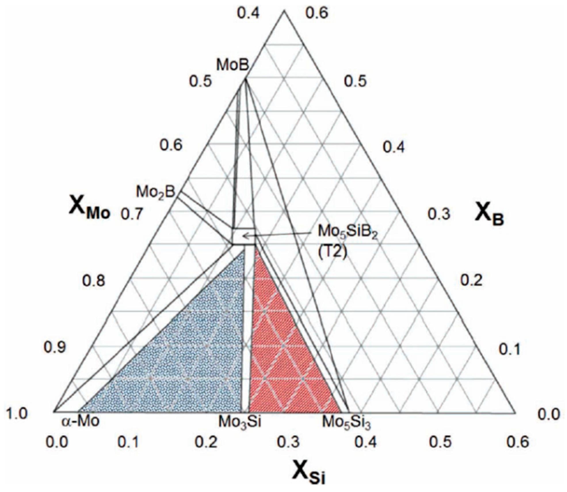
3. Microstructure of Mo–Ti–Si–B Alloy Systems

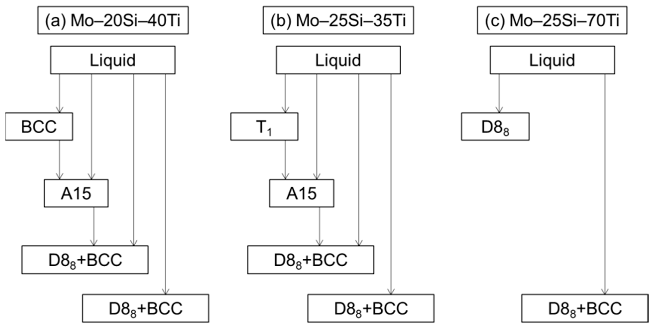
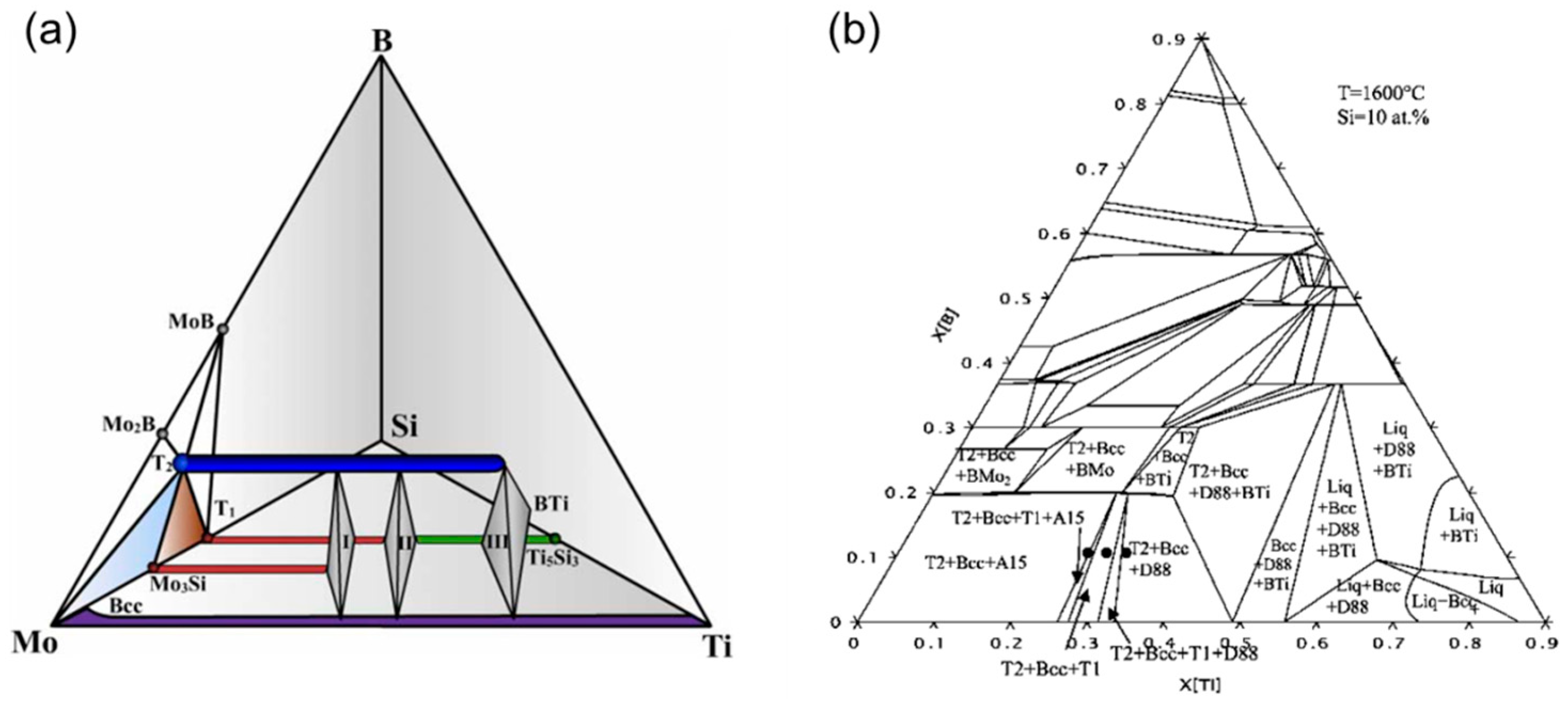
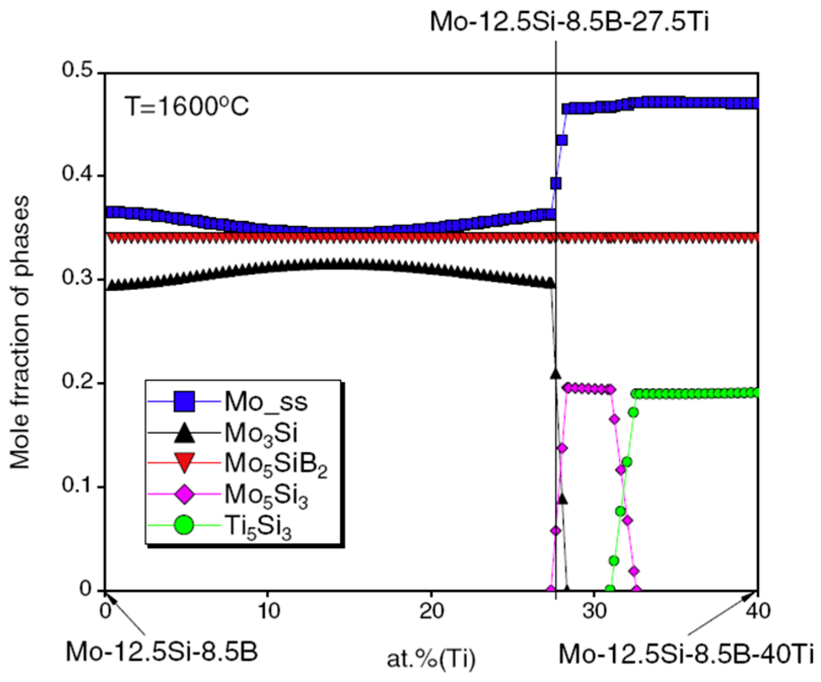
3.1. Thermal Dynamic Calculation

The phase constitution of Mo–Ti–Si–B systems has been systematically investigated during the past 20 years [36,37,41,42]. In order to gain better understanding of this quaternary alloy, the thermodynamic description of the ternary Mo–Ti–Si system was firstly studied with the combination of CALPHAD (Calculation of Phase Diagram) approaches and experimental observation [41]. Typical solidification sequences were determined for the metal-rich Mo–20Si–40Ti, Mo–25Si–35Ti and Mo–25Si–70Ti alloys (at.%). For Mo–20Si–40Ti, the primary phase during solidification is BCC((Mo,Si,Ti)ss). After that, the A15 phase forms through the peritectic ridge of L+(Mo,Si,Ti)ss→(Mo,Ti)3Si and is then partially decomposed by the reaction of L+(Mo,Ti)3Si→(Ti,Mo)5Si3(D88)+(Mo,Si,Ti)ss. Finally, the eutectic microstructure arises via L→(Ti,Mo)5Si3+(Mo,Si,Ti)ss. For Mo–25Si–35Ti, the primary phase is (Mo,Ti)5Si3(T1). Then the peritectic ridge of L+ (Mo,Ti)5Si3→(Mo,Ti)3Si takes place and the rest of the solidification path is the same as that of Mo–20Si–40Ti. These alloys are thereby composed of BCC, A15 and D88 phases. However, for Mo–25Si–70Ti, the primary phase becomes D88 and then the (Ti,Mo)5Si3+(Mo,Si,Ti)ss eutectic forms. No A15 comes out. (The version and principle calculation parameters can be found in Ref. [41]). Figure 4 illustrates a brief flow chart of the solidification sequence for these three alloys. It is suggested that with more Mo atoms replaced by Ti atoms in the metal-rich Mo–Ti–Si system, one of the base phases of A15 in traditional Mo–Si–B alloys would be gradually substituted by the D88 phase.
Based on the above results, multiphase equilibria in the metal-rich region of Mo–Ti–Si–B system were carefully investigated [36,37]. The key alloys, based on the constituent phases of BCC, T2, T1, D88 and A15, were selected with the guidance of the phase diagram calculated from thermodynamic modeling using the commercially available software package Pandat (Version 7). Figure 5a [36] demonstrates the calculated Mo–Ti–Si–B isothermal tetrahedron at 1600 °C, but only the phase relationships involving BCC, T2, T1, D88 and A15 are schematically shown considering the current focused interests. The widths of two horizontal lines represent two narrow single-phase zones of T2 (dark blue) and BCC (purple).
Here I, II and III represent three four-phase regions of BCC+A15+T2+T1, BCC+T2+T1+D88 and BCC+T2+D88+BTi. Spaces between these regions are four different three-phase windows, i.e., A15+T2+T1 and BCC+A15+T2 on the left side of Region I, BCC+T2+T1 between Region I and Region II, and BCC+T2+D88 between Region II and Region III. Figure 5b [36] manifests the slice of 10 at.% Si taken from the tetrahedron in Figure 5a. The above three-phase windows, except for the A15+T2+T1 that does not include the ductile BCC phase, can be clearly distinguished at the Mo-rich corner. It should be noted that the three-phase equilibrium of BCC+T2+T1 is much narrower than the other two windows. It is also revealed that this three-phase equilibrium is more stable at low temperatures than it is at high temperatures. Therefore, if the target microstructure is BCC+T2+T1, the compositional requirement will be strict and the desired alloy has less tolerance at high temperatures than at low temperatures. Recall that in the view of microstructure optimization for the Mo–Ti–Si–B alloys, the multi-phase equilibria of BCC+T2+A15, BCC+T2+T1, BCC+T2+D88, BCC+T2+A15+T1 and BCC+T2+T1+D88 are combinations of both the ductile BCC phase and the strengthening intermetallic compounds, which is promising for the improved mechanical properties. For instance, Mo–37.5Ti–18Si–9B locates in the BCC+T2+D88 field whereas Mo–28.5Ti–18Si–9B and Mo–32.5Ti–18Si–9B do so in the fields of BCC+T2+A15+T1 and BCC+T2+T1+D88, respectively (at.%) [37]. Additionally, the microstructures based on the three-phase equilibria of BCC+T2+T1 and BCC+T2+D88 are expected to afford better oxidation resistance than those on BCC+A15+T2 due to a higher Si concentration. In other words, macroalloying of Ti stabilizes the BCC phase to the high Si content, where the A15 phase can be totally suppressed as in the Mo–Ti–Si system.
The effects of macroalloyed Ti on the phase equilibria of Mo–Ti–Si–B alloys are further studied focused on the ones with the Si and B contents of 12.5Si–8.5B and 9Si–8B (at.%) [42,43]. For instance, Figure 6 demonstrates the calculated mole fractions of constituent phases in (79 − x)Mo–xTi–12.5Si–8.5B (0 ≤ x ≤ 40, at.%) at 1600 °C [42]. It is clearly seen that with increasing Ti content, the phase equilibrium of this alloy changes in the sequence of “BCC+A15+T2”, “BCC+A15+T2+T1”, “BCC+T2+T1”, “BCC+T2+T1+D88” and “BCC+T2+D88”. In addition, a considerable number of Ti atoms can be dissolved into the BCC, A15, T1 and T2 phases. The phase equilibrium of the 9Si–8B alloy has a similar tendency that is not shown here. Apparently, Ti content acts as one of the most crucial parameters for the microstructure development in the Mo–Ti–Si–B quaternary systems. With this guidance, the target phase constitution, or the desired microstructure, may be successfully tailored.

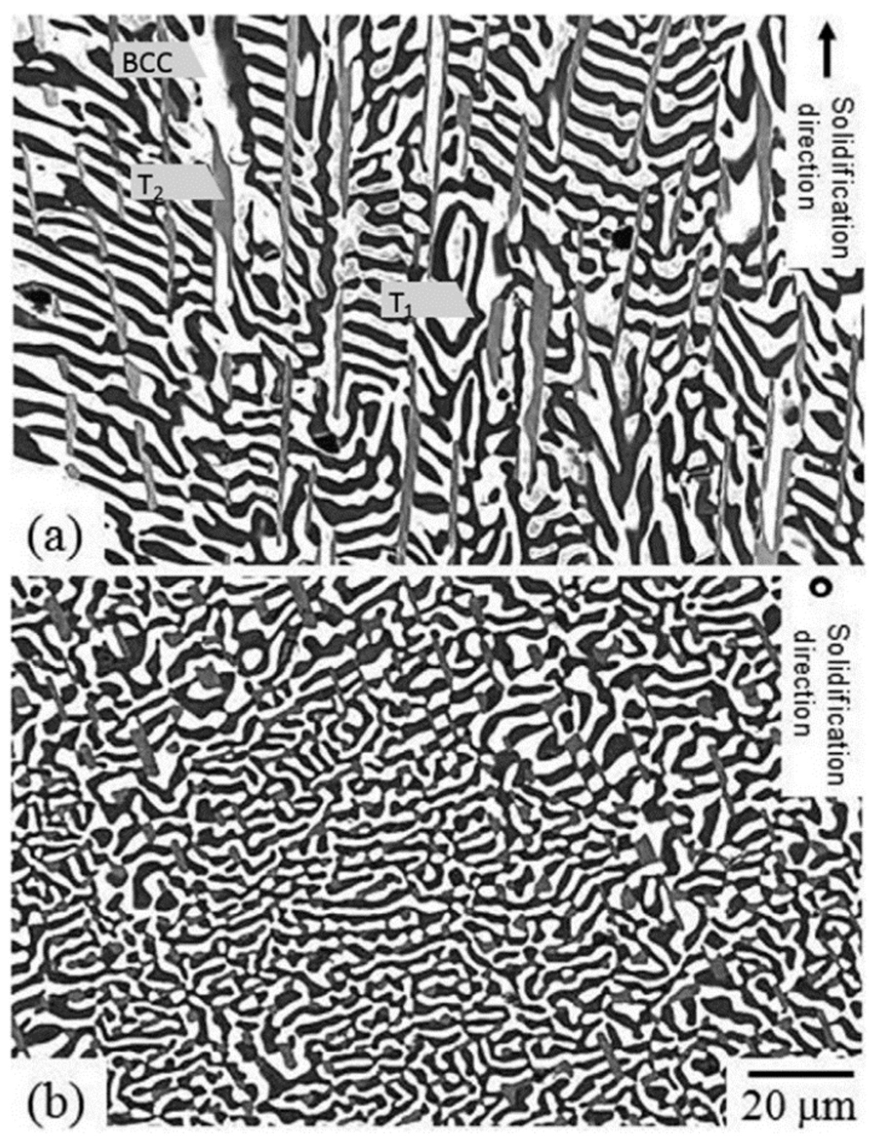
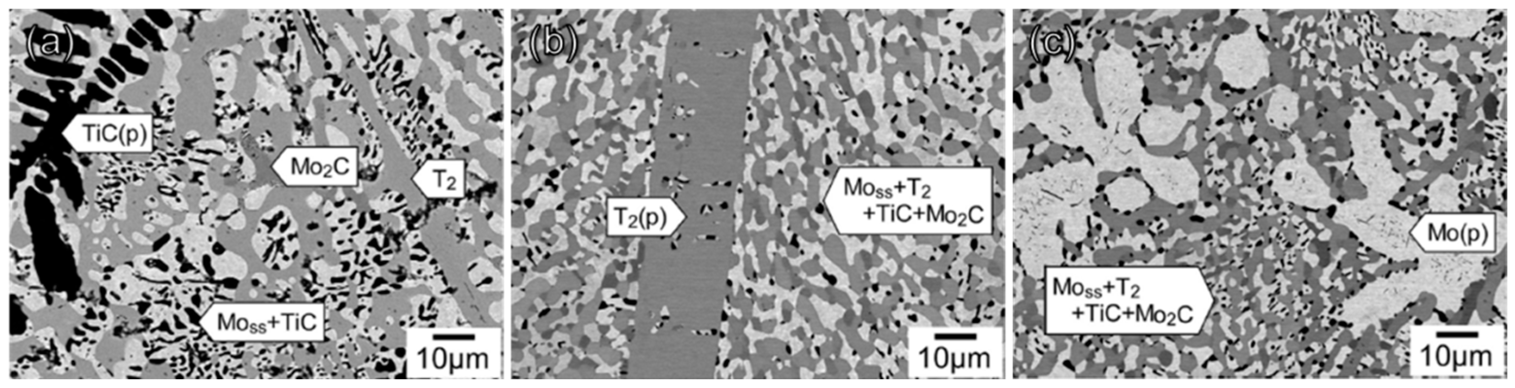
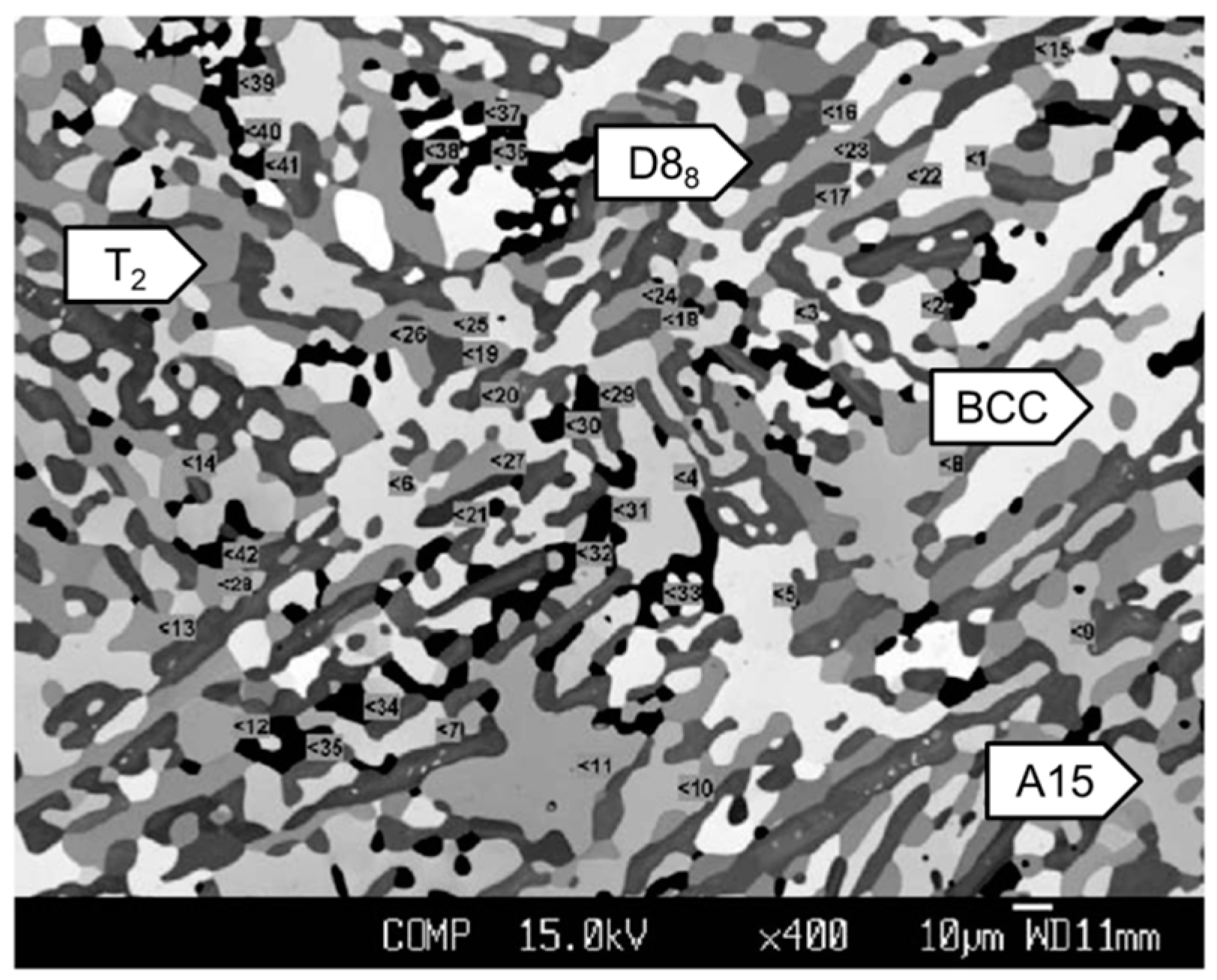
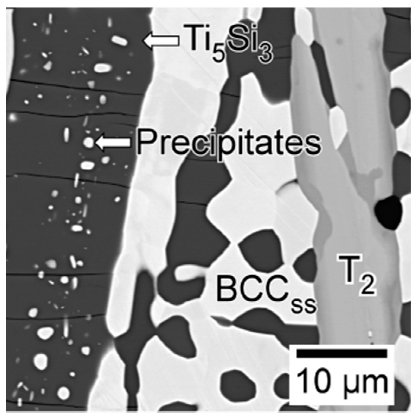
3.2. Experimental Characterization

In order to obtain the BCC-containing Mo–Ti–Si–B alloys, two kinds of alloys with the compositions of Mo–27.5Ti–12.5Si–8.5B and Mo–29Ti–9Si–8B (at.%) were designed and prepared based on the thermodynamic calculation [42,43]. They should possess the phase equilibria of BCC+A15+T2+T1 and BCC+T2+T1, respectively, if the thermodynamic prediction holds true. These alloys were obtained by arc-melting and annealed at 1600 °C for 150 h in vacuum to reach phase equilibrium. Figure 7 [42] shows the representative microstructure of the annealed Mo–27.5Ti–12.5Si–8.5B, where the white, light grey, dark grey and black phases in these SEM-BSE images refer to the BCC, A15, T2 and D88 phases, respectively. A similar microstructure had been found for Mo–29Ti–9Si–8B, except for the absence of A15 [43].
Contrary to the thermodynamic predictions as stated in Section 3.1, the desired T1 phase appeared in neither of the alloys [43]. Instead, a small amount of the D88 phase was observed in both of them. The reason for the discrepancy between the calculation and the experimental results has not been clarified yet, but the strong thermal stability of the D88 phase may give it the chance to form in the alloys. It should be mentioned that as predicted by thermodynamic calculation, the high solubility of Ti in every phase was observed, which led to a density reduction of nearly 18% as compared with the reference Mo–Si–B alloy [44]. The density reduction is one of the most attractive advantages for the macroalloying of Ti over other BCC stabilizers [23].
For microstructure optimization, the composition dependence of the phase constitution of the alloys was further studied. Before the detailed study on Mo–Ti–Si–B quaternary alloys, the Mo–Ti–Si system was first analyzed. In order to reduce the lateral dimensions of constituent phases, which is required for a better oxidation resistance [26], the eutectic and eutectoid Mo–Ti–Si alloys were designed and studied by Schliephake et al. [45]. These two alloys were composed of BCC+D88 and BCC+D88+T1, respectively. The alloy compositions were selected based on the simulation results, especially focusing on two distinct reactions of (1) L→BCC+D88 and (2) A15→BCC+T1. In their study, the composition of the eutectic alloy was decided to be Mo–52.8Ti–20.0Si whereas that of the eutectoid one was Mo–34Ti–21Si (at.%). Regarding these two alloys as references, Obert et al. [46] further studied the other two metal-rich Mo–Ti–Si alloys with tailored eutectic-eutectoid microstructures comprising minor volume fractions of primary solidified BCC. For the eutectic structure, it seems that both phases presented as laterally expanded interconnecting networks, which is not possible to assign to the matrix-forming phase [47]. In addition, all of these alloys possess fine-scaled microstructures.
Except for the formation of the T2 phase, microstructure evolution in the Mo–Ti–Si–B quaternary alloys with increasing Ti content does not seem to make much difference compared with that of Mo–Ti–Si alloys. Zhao et al. [48] designed and investigated three kinds of cast Mo–Ti–Si–B alloys, i.e., Mo–20Ti–20Si–10B, Mo–30Ti–20Si–10B and Mo–40Ti–20Si–10B (at.%). These alloys contained the same Si and the same B contents while having a trade-off between Mo and Ti. Phase constitution of the as-cast microstructure varied from BCC+D88+T2+T1+A15, to BCC+D88+T2+A15, and to BCC+D88+T2 with increasing Ti concentration. The situation slightly changed after high-temperature annealing (1600 °C for 24 h). Figure 8 [48] presents the microstructures of the annealed alloys.
It should be noted that the T1 phase vanished in the Mo–20Ti–20Si–10B alloy and apparent microstructure coarsening took place in the eutectic structure for all alloys. Figure 8d, which summarizes the volume fractions of constituent phases in these alloys, expresses an overall trend that the volume fractions of the BCC phase and D88 phase increase with increasing Ti concentration whereas that of the A15 phase has the opposite tendency. This result brings us the good news that even for the complex quaternary system, the phase constitution and volume fraction of each phase can be easily tailored by varying the Ti content. According to the criterion for microstructure optimization as discussed above, the Mo–40Ti–20Si–10B alloy of BCC+D88+T2 may have the most promising properties among the three compositions regarding the existence of enough BCC phase and the absence of low-Si A15 phase. In this regard, under the conditions of a well-designed alloy system, an appropriate microstructure can be achieved for the Mo–Ti–Si–B quaternary system.
It is the formation of the D88 phase in Mo–Ti–Si–B alloys that makes them different from their Mo–Si–B counterparts. High strength, low density and superior oxidation resistance of the D88 phase can no doubt give the alloy better high-temperature performance [38,39,40,49,50]. The intrinsic brittleness of intermetallic compounds, however, becomes the next challenge for these D88-containing alloys. In these alloys, the primary D88 grains are always largely elongated along the solidification direction due to a preferential growth along the c-axis [35]. Since it is a highly ordered phase, it has high susceptibility to crack formation. Microcracks are often observed across the longitudinal directions of these alloys [35]. According to previous studies [38], these microcracks should be initiated by the local density of microvoids, residual stress fields and the anisotropy of the linear coefficient of thermal expansion (CTE). The CTE of D88-Ti5Si3 is 5.058 × 10⁻⁶ K−1 along the a-axis and 22.197 × 10⁻⁶ K−1 along the c-axis [51], yielding a thermal expansion anisotropy of ∼4.4 at room temperature. The cooling process leads to the anisotropic shrinkage of this phase, and gives rise to microcracking perpendicular to its a-axis. Recall that the D88-Ti5Si3 compound in the Mo–Ti–Si–B system is always off-stoichiometric with a considerable amount of Mo dissolved. Upon annealing, Mo-rich BCC particles can precipitate within the primary D88 grains by the diffusion of supersaturated Mo atoms [35,48,52,53]. The BCC precipitates (see Figure 9 [53]) are promising for enhancing the toughness of the alloy by inhibiting the propagation of microcracks within the D88 matrix.
Hatakeyama et al. [53] analyzed the orientation relationship between BCC precipitates and the D88 matrix of the Mo–50Ti–14Si–6C–6B (at.%) alloy (see Figure 10). They found that the faceted interfaces between BCC and D88 meet an edge-to-edge [54] matching that produces low energy and are stochastically favored during solid-state precipitation. Thanks to these thermally stabilized BCC precipitates and their low-energy interfaces, the toughness of these alloys may be improved by the crack bridging or crack deflection mechanisms if the size and distribution of the precipitates are carefully tailored through an appropriate annealing process.

4. Properties of the Mo–Ti–Si–B Alloy System

4.1. Mechanical Properties

As one of the representative phases in the Mo–Ti–Si–B system, the deformation behavior of the D88 grains plays a significant role in the mechanical properties. Umakoshi and Nakashima [55] investigated the high-temperature deformation behavior of Ti5Si3 single crystals several decades ago. It was found that the yield stress had strong orientation dependence and numerous twins were observed in the deformed specimens since the deformation of Ti5Si3 crystals was mainly controlled by twinning with a { 10 1 ¯ 2 } 10 1 ¯ 1 ¯ system. After that, Kishida et al. [56] carefully studied the plastic deformation mechanism of this D88 phase. It was proved that prismatic slip, pyramidal slip and twinning, depending on the loading axis, were operative at temperatures above 1300 °C.
In the multiphase Mo–Ti–Si–B-based alloys, despite its off-stoichiometry, the D88 phase is deformable at high temperatures. Generally, these alloys exhibit excellent high-temperature strength. Zhao et al. [35] investigated the compressive deformation behavior of the D88-containing Mo–30Ti–17Si–10C–5B (at.%) alloy at 1500 °C, and found it impressive that the ultimate compressive strength of this alloy could exceed 500 MPa. In addition, this alloy possessed good deformability at high temperatures and macrocracks were hardly seen on the specimen surface even if the total plastic strain (true strain) reached 79%. Figure 11 [35] manifests the Inverse Pole Figure (IPF) maps of the BCC ((a,b)), D88 ((c,d)) and T2 ((e,f)) phases before ((a,c,e)) and after ((b,d,f)) high-temperature compression tests.
It was revealed that both the BCC and D88 phases displayed some ductility at this testing temperature. Recall that the ductile-brittle transition temperature (DBTT) of the D88 is about 1200 °C [57]. In this regard, the dynamic recovery and recrystallization can easily take place, not only in BCC but also in D88 during deformation at 1500 °C. As it can be seen in Figure 11b,d, numerous grain boundaries were generated within the isolated BCC and D88 phases. In contrast, The DBTT of T2 is approximately 1500 °C [57], which reaches the same level as the testing temperature. Therefore, the T2 phase could still act as the strengthening phase without dynamic recrystallization, which was responsible for the excellent high-temperature strength of the alloy.
As for high-temperature structural materials, enhancing the high-temperature creep resistance of these novel Mo–Ti–Si–B alloys is one of the most crucial issues in their engineering application. Schliephake et al. [43] tested the compressive creep behavior at 1200 °C and 1300 °C of two Mo–Ti–Si–B alloys (Mo–27.5Ti–12.5Si–8.5B and Mo–29Ti–9Si–8B, at.%) for the first time. Rather than the pronounced microstructural changes during creep such as rafting in single crystalline Ni-based superalloys, it was found that the aforementioned two alloys possessed relatively stable microstructures and near-steady-state creep conditions. The stress exponents appeared to be between 3 and 3.5, indicating a dislocation climb-controlling creep mechanism for both of the alloys. It should be mentioned that the strain rate of monolithic Ti5Si3 at 1200 °C was reported to be approximately 10−6 s−1 at 100 MPa with a stress exponent of 3 [38]. Since the strain rate of pure Ti5Si3 is two orders of magnitude higher than that of the multiphase Mo–Ti–Si–B alloys, the D88 phase is believed to participate in the creep process. The activation energy of Mo–29Ti–9Si–8B was estimated to be comparable to that of Mo self-diffusion, suggesting that bulk diffusion of Mo atoms in the BCC phase might play the major role in creep deformation of the alloy. Hereafter, Azim et al. [58] further studied the creep behavior of several Mo–Ti–Si–B alloys with different phase constitutions in the temperature range of 1100 °C–1300 °C. Unlike the T2 phase, which hardly crept at the testing temperature, the intermetallic phases of A15 and D88 could be deformed during creep, in which many dislocations were observed after the tests. Most recently, Hatakeyama et al. [34] tested the Mo–28Ti–14Si–6B–6C (at.%) alloy at 1200 °C–1300 °C and 100 MPa–300 MPa. Based on the experimental data, they yielded the apparent activation energy of this alloy at 300 MPa to be 639 kJ/mol. Since this value was close to the activation energy of the monolithic D88 compound (620 kJ/mol–640 kJ/mol [59]), a significant contribution from the D88 phase to the creep deformation of the alloys can be understood. Comparison has been made for the creep behavior at 1200 °C between this alloy and other common high-temperature materials. Figure 12 [34] summarized the minimum creep rate of different alloy systems as a function of density-normalized applied stress, indicating the excellent creep resistance of this Mo–28Ti–14Si–6B–6C alloy.
Note that the testing temperature (1200 °C) approaches the solvus temperature of the γ′ phase in a single-crystal Ni-based superalloy CMSX-4; the creep strength of CMSX-4 is markedly inferior to those of the Mo–Si–B- or Mo–Ti–Si–B-based alloys [60]. Moreover, good news comes that the newly developed Mo–Ti–Si–B or TiC-added Mo–Ti–Si–B alloys manifested superior creep resistance to that of the well-studied traditional Mo–Si–B alloys, partially attributed to the solid-solution strengthening by larger amounts of solute elements in the BCC phase.
Hatakeyama et al. [34] also briefly investigated the room-temperature fracture toughness of the above TiC-added Mo–Ti–Si–B alloy, which was determined to be (12.8 ± 1.2) MPa (m)1/2 according to their three-point bending tests. It was also proved that the Si content in the BCC phase, which could be easily adjusted by varying the annealing temperature, played a significant role in the fracture toughness of the alloy. Generally, a lower Si content results in a better fracture toughness for alloys with identical volume fractions of constituent phases.

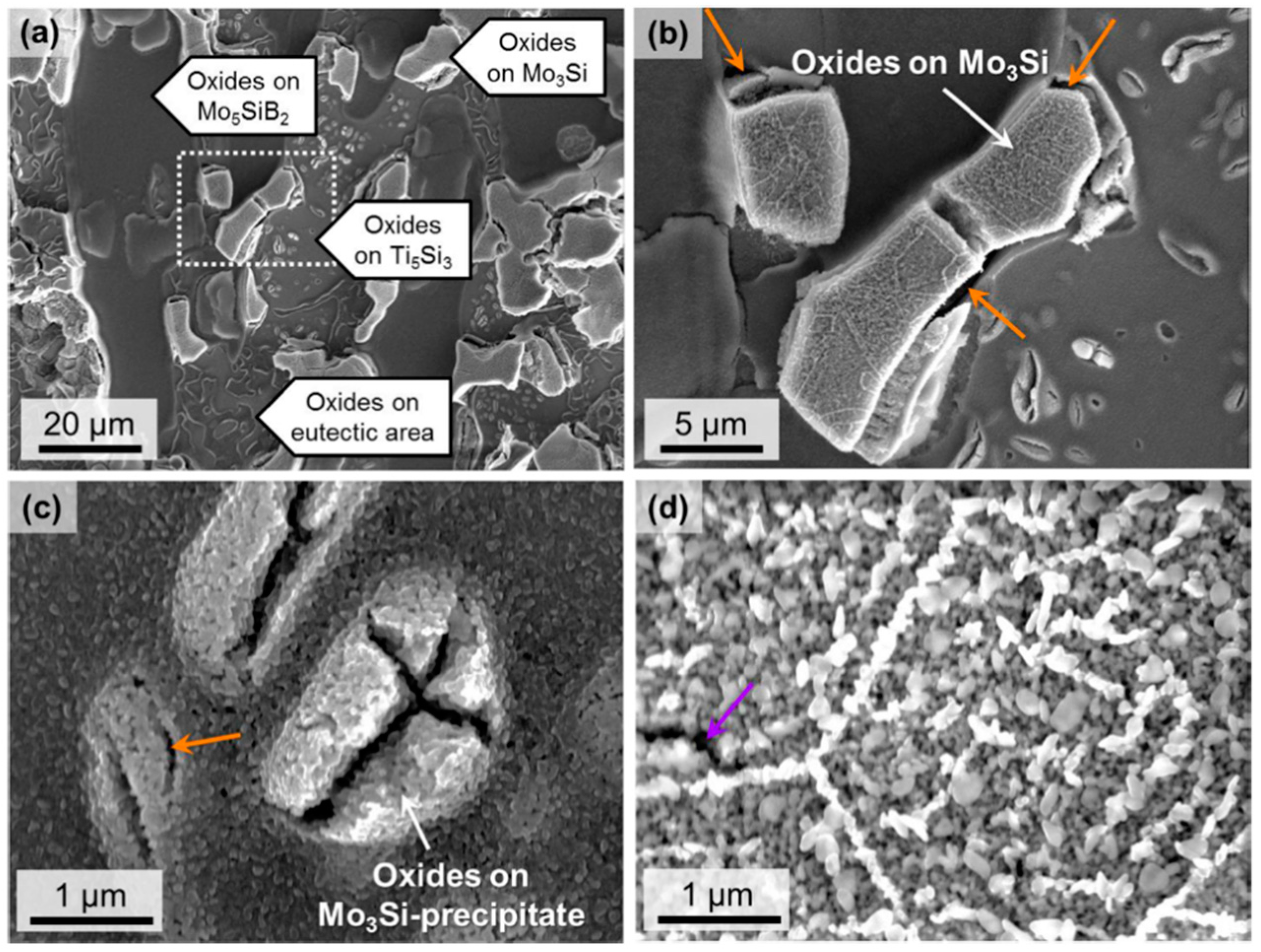
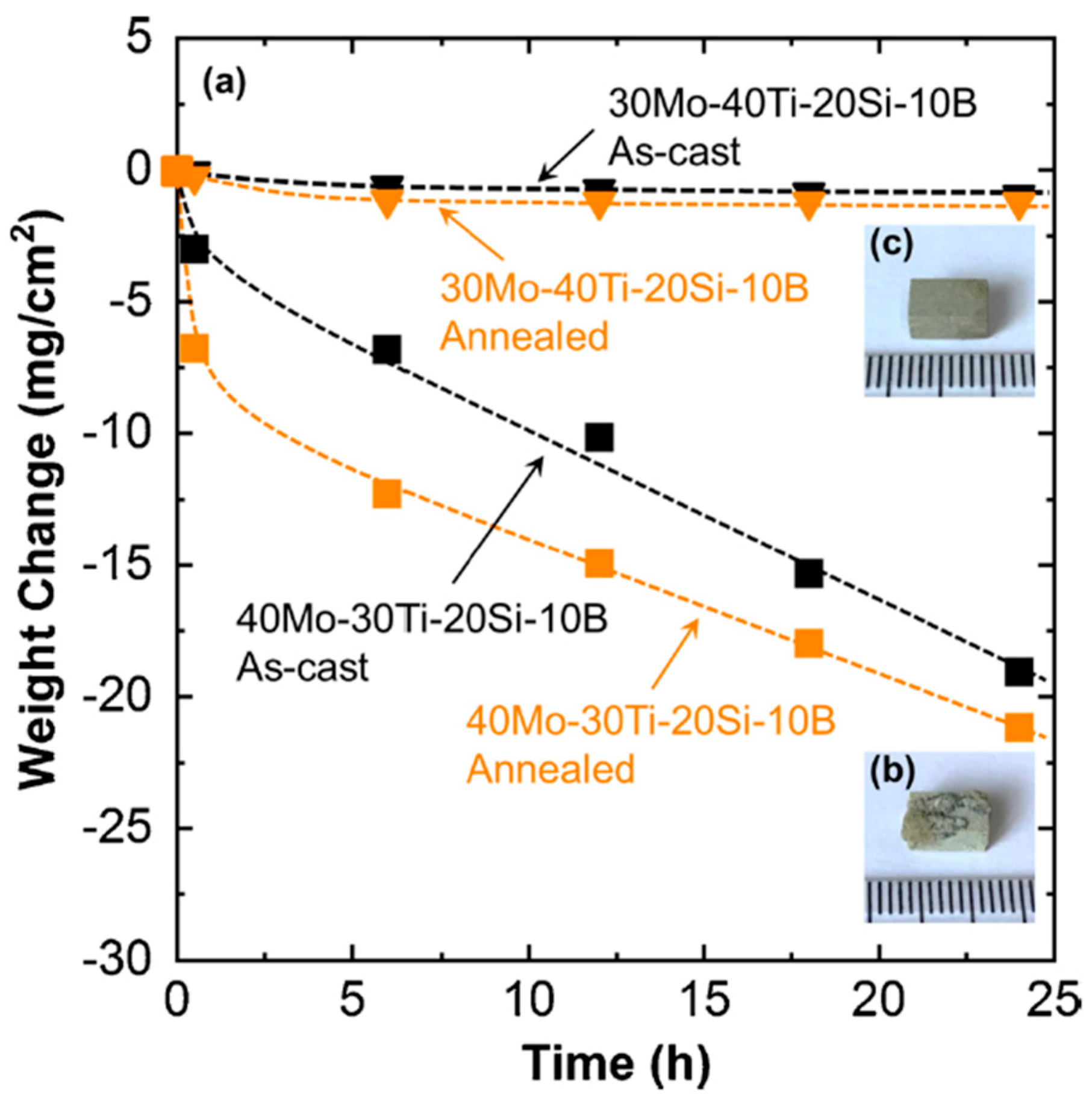
4.2. Oxidation Behavior

As it is widely understood, refractory metal-based alloys and composites always suffer from poor oxidation resistance at elevated and high temperatures because of the volatile oxidation products from the refractory metal elements. The novel Mo–Ti–Si–B alloys contain a considerable amount of Mo, whose main product, MoO3, starts to severely volatilize at 750 °C [61]. The suppression of the vitalization of MoO3 should be a crucial issue for the enhancement of the oxidation resistance of these alloys. The first report concerning the oxidation behavior of Mo–Ti–Si–B alloys was presented by Azim et al. [62] around 10 years ago. They tested the oxidation behavior of Mo–29Ti–9Si–8B and Mo–27.5Ti–12.5Si–8B (at.%) alloys in the temperature range between 820 °C and 1300 °C. It was revealed that the oxidation kinetics became totally different at intermediate and high temperatures, and both of the alloys showed rapid mass loss at 820 °C and 1000 °C [62].
Pest degradation occurred at an intermediate temperature range (below 1000 °C), indicated by the rapid mass loss upon oxidation. This is similar to the oxidation behavior of some molybdenum silicides [63,64] and the Mo–Si–B ternary alloys [19,65]. Fortunately, the oxidation resistance at higher temperatures (above 1000 °C) seems not to be disappointing. The oxidation scale formed at high temperatures is reported to be composed of four layers, i.e., an outermost TiO2-predominant layer, a duplex layer composed of crystalline-TiO2 and amorphous-SiO2, an interlayer mainly consisting of MoO2 and an inner oxidation zone after long-time oxidation. A significant reduction in the initial evaporation rate of MoO3 was realized in these quaternary alloys beyond 1000 °C compared with the referring Mo–Si–B alloys. After that, Nan et al. [66] further analyzed the oxidation kinetics of a TiC-added Mo–Ti–Si–B alloy with the nominal composition of Mo–37Ti–17Si–5B–10C (at.%) during oxidation from 700 °C to 1100 °C. Except for a short-term weight gain before switching to weight loss at 700 °C, the specimens exhibited continuous weight loss at all the other testing temperatures, and the most rapid weight-loss rate appeared at 800 °C as a result of the troublesome pest phenomenon (see Figure 13 [66]). At 900 °C and 1000 °C, the weight loss could be fitted to parabolic rate kinetics with the rate of 0.49 mg2/cm4/h and 3.51 mg2/cm4/h, respectively [66].
According to the aforementioned results, it is reasonable to reach the common-sense conclusion that the suppression of pest degradation should be the next task for developing novel Mo–Ti–Si–B-based alloys. To gain a better understanding of the pest phenomenon, especially the influence of phase constitution and alloy composition on it, Schliephake et al. [45] tested the BCC+D88 alloy (eutectic alloy) of Mo–52.8Ti–20Si and the BCC+D88+T1 alloy (eutectoid alloy) of Mo–34Ti–21Si (at.%) under isothermal and cyclic oxidation conditions. It was impressive that the eutectic alloy was pest-resistant, successfully protected by a homogeneous layer of a mixture of TiO2 and SiO2. In contrast, the eutectoid one experienced catastrophic degradation and was completely oxidized. It should be mentioned that the amount of non-protective BCC phase was almost equivalent in these two alloys, and the lateral dimension of the BCC phase was even smaller in the catastrophically failed eutectoid one. In their opinion, the volume fraction of BCC phase and its size scale were not decisive in the formation of protective oxide scale. After that, Obert et al. [46] further studied the oxidation behavior of several D88-containing Mo–Ti–Si systems, which should be helpful when it comes to the more complex Mo–Ti–Si–B quaternary system. They proposed that the threshold for the pest-resistant alloys lay in a nominal Ti content of minimum 43 at.% and an average Ti content in BCC of minimum 35 at.%. Then, they proved that the Ti content was one of the most significant influencing factors contributing to the intermediate-temperature oxidation resistance [47]. Moreover, Lu et al. [67] pointed out that the D88-containing alloys could achieve good oxidation resistance at up to 900 °C benefiting from the self-healing ability where the amorphous SiO2 seals the clearances between the TiO2 grains.
Phase constitution and phase equilibria, which also largely rely on the Ti content, are no doubt more complicated in Mo–Ti–Si–B alloys. Zhao et al. [48] carefully studied the series of Mo–(70 − x)Ti–20Si–10B (x = 20, 30, 40; at.%) quaternary alloys with different phase constitutions as discussed in above mentioned section. It was interesting to find that the A15 phase manifested the worst oxidation resistance especially at the initial stage of oxidation at 800 °C; its oxidation products were full of microcracks and were totally porous (see Figure 14 [48]).
The pest degradation often occurs in alloys containing a considerable amount of the A15 phase. In these alloys, the swelling of the oxide products with porous structure is one of the main reasons leading to the pest phenomenon. In addition, due to its porous nature, oxygen can easily penetrate through the scale and give rise to a thick and high-oxygen-containing internal zone. As a result, catastrophic degradation rapidly proceeds. Fortunately, pest phenomenon can be successfully prevented if the volume fraction of A15 phase is suppressed. For the A15-free Mo–Ti–Si–B alloy, of course with a high Ti content, a thin and stable passive film can form and protect the specimens, resulting in a negligible mass loss during long-term oxidation at 800 °C (see Figure 15 [48]). Therefore, it is the high Ti content accompanied by the simple phase constitution (BCC+D88+T2) that brings about the pest-resistant novel Mo–Ti–Si–B alloys [48,52].
The oxidation resistance of the alloys can be further enhanced through alloying. For instance, Al and Cr are proven to be effective to improve the oxidation resistance of D88-incorporated Mo–Ti–Si–B, TiC-added Mo–Ti–Si–B and other Mo-based alloys [27,68,69,70]. The passive effect is mainly attributed to the formation of Cr2(MoO4)3 and Al2(MoO4)3 complex oxides at intermediate temperatures and Cr2O3 and Al2O3 at high temperatures. In particular, it should be noted that the replacement of Cr (at least up to 10 at.%) for Mo hardly changes the phase constitution of the alloys [69], allowing it to preserve the advantages in the microstructure and thereby in the mechanical properties. That is to say, the presence of a high-volume fraction of the BCC phase, which contributes to the fracture toughness, is feasible in these Cr-added alloys. Besides Al and Cr, microalloying of rare earth elements might also make sense. In previous studies, it was revealed that the addition of Y, La and Ce could result in the improved oxidation resistance of Mo–Si–B and Nb–Si alloys [71,72,73,74,75,76]. Since minor addition of rare earth elements usually brings about remarkable outcomes, the simultaneous optimization of microstructure and oxidation resistance of the newly developed Mo–Ti–Si–B-based alloys, we believe, will also be realized by the rare earth element modification.

5. Outlook

For a long time, the coexistence of a high volume fraction of BCC phase and intermetallic compounds of high Si content was seldom possible in traditional ternary Mo–Si–B alloys, making it difficult to adjust their mechanical properties and oxidation resistance simultaneously. According to the description and analysis stated above, it is reasonable to understand that macroalloying of Ti into a Mo–Si–B system can give it a better balance between the ductile phase (BCC solid solution) and the intermetallic strengthening phases (such as T2 and D88 compounds). In the newly developed Mo–Ti–Si–B quaternary alloys, a larger volume fraction of BCC phase can be preserved even if the alloy possesses a high Si content. Moreover, the microstructure and phase equilibria can be easily tailored by varying the Ti concentration. Further optimization for the improved performance of high-temperature creep resistance, room-temperature fracture toughness and intermediate-to-high temperature oxidation resistance should be continuously focused on. The following aspects can be addressed.
  • Multi-element alloying. The BCC phase that suffers from the worst oxidation resistance should be further modified by alloying. The ductility of the alloys may also be improved through microalloying.
  • Innovation of alloy preparation process. Besides the traditional arc-melting and powder metallurgy, additive manufacturing should be tested to study the formability of this in situ compound.
  • Preparation of environmental barrier coatings. Environmental barrier coatings often act as one of the most effective methods to improve the corrosion resistance of high-temperature materials. New types of coatings should be developed for novel alloys.
In this regard, we believe that novel ultra-high-temperature structural materials beyond Ni-based or Mo–Si–B-based alloys will come to the stage in the near future.

Author Contributions

Conceptualization, M.Z. (Mi Zhao) and W.G.; formal analysis, Y.G.; resources, W.Y.; data curation, M.Z. (Mi Zhao), Y.G. and M.Z. (Mengyuan Zhu); writing—original draft preparation, M.Z. (Mi Zhao); writing—review and editing, W.G.; supervision, S.W. and Y.Y.; project administration, S.W. and Y.Y.; funding acquisition, W.G. All authors have read and agreed to the published version of the manuscript.

Funding

This research was funded by National Nature Science Foundation of China (No. 52201075, 52101138), Natural Science Foundation of Hubei Province (2022CFB614), Guangdong Basic and Applied Basic Research Foundation (No. 2020A1515110531, No. 2022A1515011227), Shenzhen Science and Technology Program (No. JCYJ20220530160813032), State Key Laboratory for Mechanical Behavior of Materials (No. 20202205), State Key Laboratory of Materials Processing and Die & Mold Technology, Huazhong University of Science and Technology (No. P2021-021) and State Key Lab of Advanced Metals and Materials (No. 2020-Z01).

Acknowledgments

This work was supported by the Project supported by National Nature Science Foundation of China (No. 52201075, 52101138), Natural Science Foundation of Hubei Province (2022CFB614), Guangdong Basic and Applied Basic Research Foundation (No. 2020A1515110531, No. 2022A1515011227), Shenzhen Science and Technology Program (No. JCYJ20220530160813032), State Key Laboratory for Mechanical Behavior of Materials (No. 20202205), State Key Laboratory of Materials Processing and Die & Mold Technology, Huazhong University of Science and Technology (No. P2021-021) and State Key Lab of Advanced Metals and Materials (No. 2020-Z01). M. Zhao is also grateful to K. Yoshimi of Tohoku University for his encouragement and instructive advice.

Conflicts of Interest

The authors declare no conflict of interest.

Appendix A

The lattice structure data of some typical compounds and their abbreviations are listed in Table A1.
Table A1. Crystal data for some intermetallic compounds.
Stoichiometric FormulaAbbreviations of Compound NameCrystal StructureStructure and Space Group
Mo3SiA15CubicPm3n
Mo5SiB2T2TetragonalI4/mcm
Mo5Si3T1TetragonalI4/mcm
Ti5Si3D88HexagonalI4/mcm
TiC/CubicFm 3 ¯ m

References

  1. Perepezko, J.H. The hotter the engine, the better. Science 2009, 326, 1068–1069. [Google Scholar] [CrossRef]
  2. Zhao, J.-C.; Westbrook, J.H. Ultrahigh-temperature materials for jet engines. MRS Bull. 2003, 28, 622–630. [Google Scholar] [CrossRef] [Green Version]
  3. Liu, L.; Zhang, J.; Ai, C. Nickel-based superalloys. Encycl. Mater. Met. Alloys 2022, 1, 294–304. [Google Scholar]
  4. Padture, N.P.; Gell, M.; Jordan, E.H. Thermal barrier coatings for gas-turbine engine applications. Science 2002, 296, 280–284. [Google Scholar] [CrossRef]
  5. Bewlay, B.P.; Jackson, M.R.; Lipsitt, H.A. The balance of mechanical and environmental properties of a multielement niobium-niobium silicide-based in situ composite. Metall. Mater. Trans. A 1996, 27, 3801–3808. [Google Scholar] [CrossRef]
  6. Bewlay, B.P.; Jackson, M.R.; Zhao, J.-C.; Subramanian, P.R. A review of very-high-temperature Nb-silicide-based composites. Metall. Mater. Trans. A 2003, 34, 2043–2052. [Google Scholar] [CrossRef]
  7. Schneibel, J.H.; Liu, C.T.; Easton, D.S.; Carmichael, C.A. Microstructure and mechanical properties of Mo–Mo3Si–Mo5SiB2 silicides. Mater. Sci. Eng. A 1999, 261, 78–83. [Google Scholar] [CrossRef]
  8. Dimiduk, D.M.; Perepezko, J.H. Mo–Si–B alloys: Developing a revolutionary turbine-engine material. MRS Bull. 2003, 28, 639–645. [Google Scholar] [CrossRef]
  9. Tsakiropoulos, P. Alloys for application at ultra-high temperatures: Nb-silicide in situ composites Challenges, breakthroughs and opportunities. Prog. Mater. Sci. 2022, 123, 100714. [Google Scholar] [CrossRef]
  10. Zhang, L.; Huang, Y.; Lin, J. Research status on ultra-high-temperature structural intermetallics of Mo–Si–B ternary system. J. Nanjing Univ. Aeronaut. Astronaut. 2016, 48, 1–9. [Google Scholar]
  11. Jain, P.; Kumar, K.S. Tensile creep of Mo–Si–B alloys. Acta Mater. 2010, 58, 2124–2142. [Google Scholar] [CrossRef]
  12. Hasemann, G.; Bogomol, I.; Schliephake, D.; Loboda, P.I.; Krüger, M. Microstructure and creep properties of a near-eutectic directionally solidified multiphase Mo–Si–B alloy. Intermetallics 2014, 48, 28–33. [Google Scholar] [CrossRef]
  13. Supatarawanich, V.; Johnson, D.R.; Liu, C.T. Oxidation behavior of multiphase Mo–Si–B alloys. Intermetallics 2004, 12, 721–725. [Google Scholar] [CrossRef]
  14. Helmick, D.A.; Meier, G.H.; Pettit, F.S. The development of protective borosilicate layers on a Mo–3Si–1B (Weight Percent) alloy. Metall. Mater. Trans. A 2005, 36, 3371–3383. [Google Scholar] [CrossRef]
  15. Jéhanno, P.; Böning, M.; Kestler, H.; Heilmaier, M.; Saage, H.; Krüger, M. Molybdenum alloys for high temperature applications in air. Powder Metall. 2008, 51, 99–102. [Google Scholar] [CrossRef]
  16. Lemberg, J.A.; Ritchie, R.O. Mo–Si–B alloys for ultrahigh-temperature structural applications. Adv. Mater. 2012, 24, 3445–3480. [Google Scholar] [CrossRef]
  17. Schneibel, J.H.; Kramer, M.J.; Easton, D.S. A Mo–Si–B intermetallic alloy with a continuous α-Mo matrix. Scr. Mater. 2002, 46, 217–221. [Google Scholar] [CrossRef]
  18. Meyer, M.K.; Thom, A.J.; Akinc, M. Oxide scale formation and isothermal oxidation behavior of Mo–Si–B intermetallics at 600–1000 °C. Intermetallics 1999, 7, 153–162. [Google Scholar] [CrossRef]
  19. Parthasarathy, T.A.; Mendiratta, M.G.; Dimiduk, D.M. Oxidation mechanisms in Mo-reinforced Mo5SiB2(T2)–Mo3Si alloys. Acta Mater. 2002, 50, 1857–1868. [Google Scholar] [CrossRef]
  20. Sakidja, R.; Myers, J.; Kim, S.; Perepezko, J.H. The effect of refractory metal substitution on the stability of Mo(ss) + T2 two-phase field in the Mo–Si–B system. Int. J. Refract. Met. Hard Mater. 2000, 18, 193–204. [Google Scholar] [CrossRef]
  21. Ito, K.; Kumagai, M.; Hayashi, T.; Yamaguchi, M. Room temperature fracture toughness and high temperature strength of T2/Moss and (Mo,Nb)ss/T1/T2 eutectic alloys in the Mo–Si–B system. Scr. Mater. 2003, 49, 285–290. [Google Scholar] [CrossRef]
  22. Takata, N.; Sekido, N.; Takeyama, M.; Perepezko, J.H.; Follett-Figueroa, M.; Zhang, C. Solidification of Bcc/T1/T2 three-phase microstructure in Mo–Nb–Si–B alloys. Intermetallics 2016, 72, 1–8. [Google Scholar] [CrossRef]
  23. Sakidja, R.; Perepezko, J.H. Alloying and microstructure stability in the high-temperature Mo–Si–B system. J. Nucl. Mater. 2007, 366, 407–416. [Google Scholar] [CrossRef]
  24. Galetz, M.C.; Ulrich, A.S.; Hasemann, G.; Krüger, M. Refractory metal-based high entropy silicide-borides: The future of materials beyond MoSiB? Intermetallics 2022, 148, 107620. [Google Scholar] [CrossRef]
  25. Yoshimi, K.; Nakatani, S.; Suda, T.; Hanada, S.; Habazaki, H. Oxidation behavior of Mo5SiB2-based alloy at elevated temperatures. Intermetallics 2002, 10, 407–414. [Google Scholar] [CrossRef]
  26. Rioult, F.A.; Imhoff, S.D.; Sakidja, R.; Perepezko, J.H. Transient oxidation of Mo–Si–B alloys: Effect of the microstructure size scale. Acta Mater. 2009, 57, 4600–4613. [Google Scholar] [CrossRef]
  27. Zhao, M.; Xu, B.; Shao, Y.; Liang, J.; Wu, S.; Yan, Y. Oxidation behavior of Moss–Ti5Si3–T2 composites at intermediate and high temperatures. Intermetallics 2020, 118, 106702. [Google Scholar]
  28. Liu, Y.; Kramer, M.J.; Thom, A.J.; Akinc, M. Oxidation behavior of multiphase Nb-Mo-Si-B intermetallics. Metall. Mater. Trans. A. 2005, 36, 601–607. [Google Scholar] [CrossRef]
  29. Behrani, V.; Thom, A.J.; Kramer, M.J.; Akinc, M. Microstructure and oxidation behavior of Nb–Mo–Si–B alloys. Intermetallics 2006, 14, 24–32. [Google Scholar] [CrossRef]
  30. Miyamoto, S.; Yoshimi, K.; Ha, S.-H.; Kaneko, T.; Nakamura, J.; Sato, T.; Maruyama, K.; Tu, R.; Goto, T. Phase equilibria, microstructure, and high-temperature strength of TiC-added Mo–Si–B alloys. Metall. Mater. Trans. A 2014, 45, 1112–1123. [Google Scholar] [CrossRef]
  31. Moriyama, T.; Yoshimi, K.; Zhao, M.; Masnou, T.; Yokoyama, T.; Nakamura, J.; Katsui, H.; Goto, T. Room-temperature fracture toughness of MoSiBTiC alloys. Intermetallics 2017, 84, 92–102. [Google Scholar] [CrossRef]
  32. Yoshimi, K.; Nakamura, J.; Kanekon, D.; Yamamoto, S.; Maruyama, K.; Katsui, H.; Goto, T. High-temperature compressive properties of TiC-added Mo–Si–B alloys. JOM 2014, 66, 1930–1938. [Google Scholar] [CrossRef]
  33. Kamata, S.Y.; Kanekon, D.; Lu, Y.; Sekido, N.; Maruyama, K.; Eggeler, G.; Yoshimi, K. Ultrahigh-temperature tensile creep of TiC-reinforced Mo–Si–B based alloy. Sci. Rep. 2018, 8, 10487. [Google Scholar] [CrossRef] [PubMed]
  34. Hatakeyama, T.; Kauffmann, A.; Obert, S.; Gombola, C.; Heilmaier, M.; Yoshimi, K. Oxidation resistance, creep strength and room-temperature fracture toughness of Mo–28Ti–14Si–6C–6B alloy. Materialia 2021, 16, 101108. [Google Scholar] [CrossRef]
  35. Zhao, M.; Nakayama, S.; Hatakeyama, T.; Nakamura, J.; Yoshimi, K. Microstructure, high-temperature deformability and oxidation resistance of a Ti5Si3-containing multiphase MoSiBTiC alloy. Intermetallics 2017, 90, 169–179. [Google Scholar] [CrossRef]
  36. Yang, Y.; Chang, Y.A.; Tan, L.; Cao, W. Multiphase equilibria in the metal-rich region of the Mo–Ti–Si–B system: Thermodynamic prediction and experimental validation. Acta Mater. 2005, 53, 1711–1720. [Google Scholar] [CrossRef]
  37. Yang, Y.; Bewlay, B.P.; Chen, S.; Chang, Y.A. Application of phase diagram calculations to development of new ultra-high temperature structural materials. Trans. Nonferrous Met. Soc. China 2007, 17, 1396–1404. [Google Scholar] [CrossRef]
  38. Rosenkranz, R.; Frommeyer, G.; Smarsly, W. Microstructure and properties of high melting point intermetallic Ti5Si3 and TiSi2 compounds. Mater. Sci. Eng. A 1992, 152, 288–294. [Google Scholar] [CrossRef]
  39. Taniguchi, S.; Minamida, T.; Shibata, T. Oxidation behaviour of Ti5Si3 at temperatures between 1400 and 1700 K. Mater. Sci. Forum. 1997, 251–254, 227–234. [Google Scholar] [CrossRef]
  40. Williams, J.J.; Akinc, M. Oxidation resistance of Ti5Si3 and Ti5Si3Zx at 1000 °C. Oxid. Met. 2002, 58, 57–71. [Google Scholar] [CrossRef]
  41. Yang, Y.; Chang, Y.A.; Tan, L.; Du, Y. Experimental investigation and thermodynamic descriptions of the Mo–Si–Ti system. Mater. Sci. Eng. A 2003, 361, 281–293. [Google Scholar] [CrossRef]
  42. Yang, Y.; Bei, H.; Chen, S.; George, E.P.; Tiley, J.; Chang, Y.A. Effects of Ti, Zr, and Hf on the phase stability of Mo_ss + Mo3Si + Mo5SiB2 alloys at 1600 °C. Acta Mater. 2010, 58, 541–548. [Google Scholar] [CrossRef]
  43. Schliephake, D.; Azim, M.; Klinski-Wetzel, K.V.; Gorr, B.; Christ, H.-J.; Bei, H.; George, E.P.; Heilmaier, M. High-temperature creep and oxidation behavior of Mo–Si–B alloys with high Ti contents. Metall. Mater. Trans. A 2014, 45, 1102–1111. [Google Scholar] [CrossRef]
  44. Jéhanno, P.; Heilmaier, M.; Kestler, H. Characterization of an industrially processed Mo-based silicide alloy. Intermetallics 2004, 12, 1005–1009. [Google Scholar] [CrossRef]
  45. Schliephake, D.; Kauffmann, A.; Cong, X.; Gombola, C.; Azim, M.; Gorr, B.; Christ, H.-J.; Heilmaier, M. Constitution, oxidation and creep of eutectic and eutectoid Mo-Si-Ti alloys. Intermetallics 2019, 104, 133–142. [Google Scholar] [CrossRef]
  46. Obert, S.; Kauffmann, A.; Heilmaier, M. Characterisation of the oxidation and creep behaviour of novel Mo-Si-Ti alloys. Acta Mater. 2020, 184, 132–142. [Google Scholar] [CrossRef]
  47. Obert, S.; Kauffmann, A.; Seils, S.; Schellert, S.; Weber, M.; Gorr, B.; Christ, H.-J.; Heilmaier, M. On the chemical and microstructural requirements for the pesting-resistance of Mo–Si–Ti alloys. J. Mater. Res. Technol. 2020, 9, 8556–8567. [Google Scholar] [CrossRef]
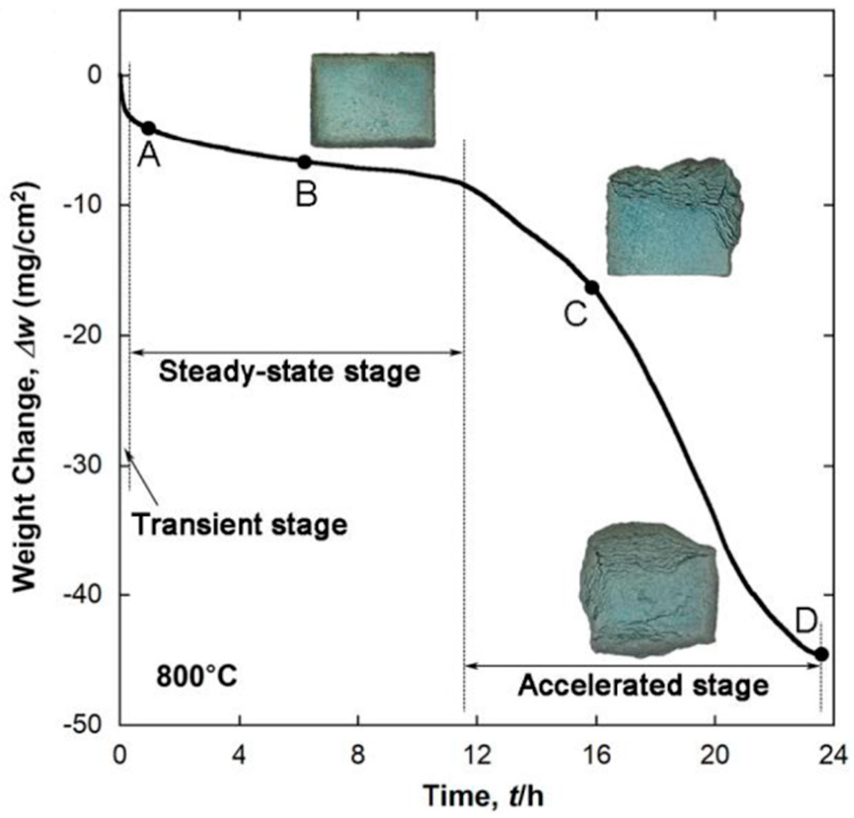
  48. Zhao, M.; Xu, B.; Shao, Y.; Zhu, Y.; Wu, J.; Wu, S.; Yan, Y. Microstructure and oxidation mechanism of multiphase Mo–Ti–Si–B alloys at 800 °C. Corros. Sci. 2021, 187, 109518. [Google Scholar] [CrossRef]
  49. Zhang, L.; Wu, J. Ti5Si3 and Ti5Si3-based alloys: Alloying behavior, microstructure and mechanical property evaluation. Acta Mater. 1998, 46, 3535–3546. [Google Scholar]
  50. Tang, Z.; Williams, J.J.; Thom, A.J.; Akinc, M. High temperature oxidation behavior of Ti5Si3-based intermetallics. Intermetallics 2008, 16, 1118–1124. [Google Scholar] [CrossRef]
  51. Zhang, L.; Wu, J. Thermal expansion and elastic moduli of the silicide based intermetallic alloys Ti5Si3(X) and Nb5Si3. Scr. Mater. 1998, 38, 307–313. [Google Scholar] [CrossRef]
  52. Hatakeyama, T.; Ida, S.; Sekido, N.; Yoshimi, K. Significant improvement of the oxidation resistance of MoSiBTiC-based multiphase alloys by Ti enrichment. Corros. Sci. 2020, 176, 108937. [Google Scholar] [CrossRef]
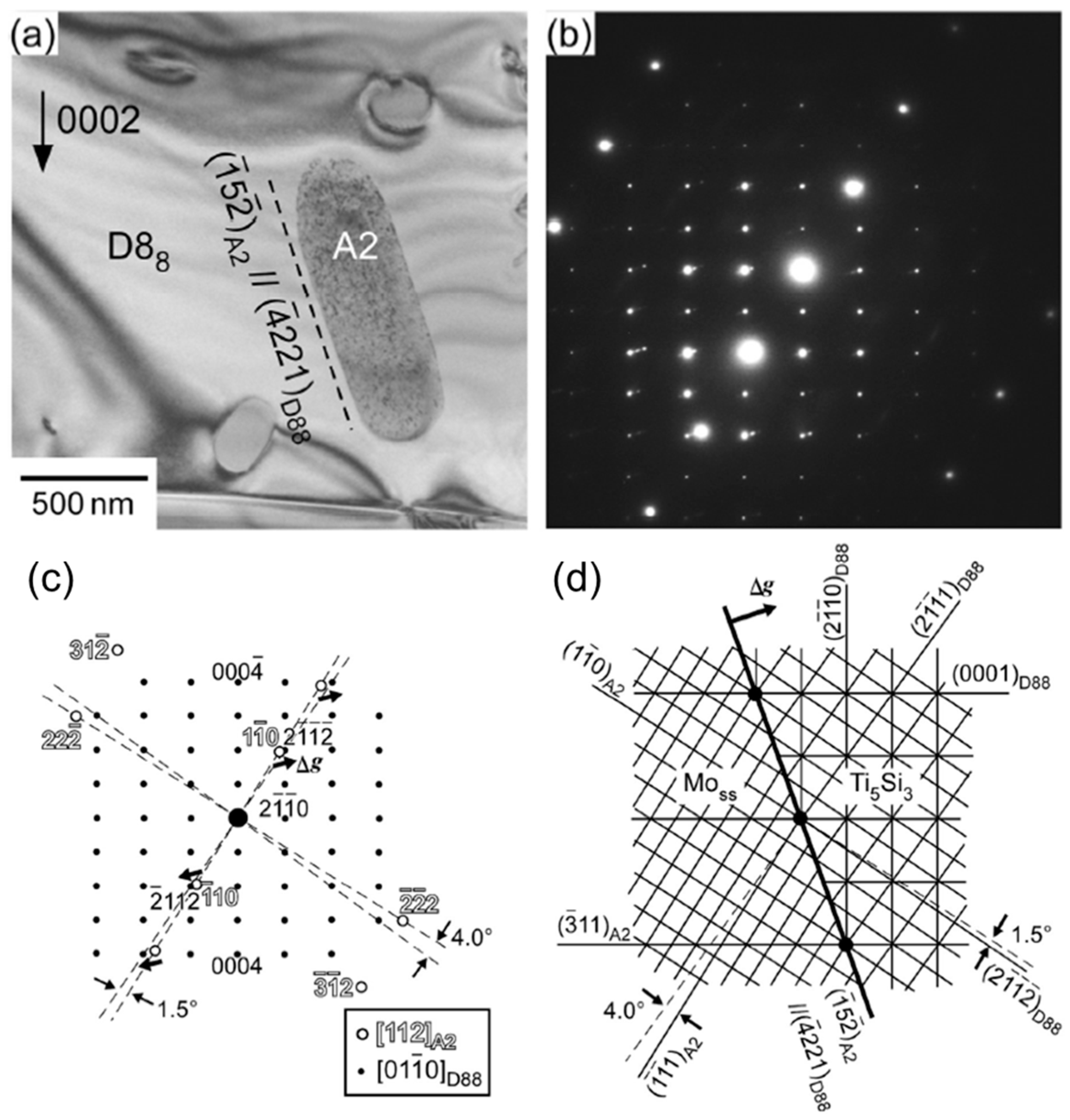
  53. Hatakeyama, T.; Sekido, N.; Kimura, Y.; Yoshimi, K. Orientation relationship between bcc precipitates and Ti5Si3 matrix in Mo–Si–B–Ti–C quinary alloys. Intermetallics 2020, 124, 106863. [Google Scholar] [CrossRef]
  54. Zhang, M.X.; Kelly, P.M. Edge-to-edge matching model for predicting orientation relationships and habit planes—The improvements. Scr. Mater. 2005, 52, 963–968. [Google Scholar] [CrossRef]
  55. Umakoshi, Y.; Nakashima, T. High temperature deformation of Ti5Si3 single crystals with D88 structure. Scr. Metall. Mater. 1994, 30, 1431–1436. [Google Scholar] [CrossRef]
  56. Kishida, K.; Fujiwara, M.; Adachi, H.; Tanaka, K.; Inui, H. Plastic deformation of single crystals of Ti5Si3 with the hexagonal D88 structure. Acta Mater. 2010, 58, 846–857. [Google Scholar] [CrossRef] [Green Version]
  57. Mitra, R. Mechanical behavior and oxidation resistance of structure silicides. Int. Mater. Rev. 2006, 51, 13–64. [Google Scholar] [CrossRef]
  58. Azim, M.A.; Schliephake, D.; Hochmuth, C.; Gorr, B.; Christ, H.-J.; Glatzel, U.; Heilmaier, M. Creep resistance and oxidation behavior of novel Mo–Si–B–Ti alloys. JOM 2015, 67, 2621–2628. [Google Scholar] [CrossRef]
  59. Sadananda, K.; Feng, C.R.; Mitra, R.; Deevi, S.C. Creep and fatigue properties of high temperature silicides and their composites. Mater. Sci. Eng. A 1999, 261, 223–238. [Google Scholar] [CrossRef]
  60. Heilmaier, M.; Krüger, M.; Saage, H.; Rösler, J.; Mukherji, D.; Glatzel, U.; Völkl, R.; Hüttner, R.; Eggeler, G.; Somsen, C.; et al. Metallic materials for structural applications beyond nickel-based superalloys. JOM 2009, 61, 61–67. [Google Scholar] [CrossRef]
  61. Meyer, M.; Kramer, M.; Akinc, M. Boron-doped molybdenum silicides. Adv. Mater. 1996, 8, 85–88. [Google Scholar] [CrossRef]
  62. Azim, M.A.; Burk, S.; Gorr, B.; Christ, H.-J.; Schliephake, D.; Heilmaier, M.; Bornemann, R.; Bolívar, P.H. Effect of Ti (Macro-) alloying on the high-temperature oxidation behavior of ternary Mo–Si–B alloys at 820–1300 °C. Oxid. Met. 2013, 80, 231–242. [Google Scholar] [CrossRef]
  63. Chou, T.C.; Nieh, T.G. Mechanism of MoSi2 pest during low temeprature oxidation. J. Mater. Res. 1993, 8, 214–226. [Google Scholar] [CrossRef]
  64. Meschter, P.J. Low-temperature oxidation of molybdenum disilicide. Metall. Trans. A 1992, 23, 1763. [Google Scholar] [CrossRef]
  65. Pan, K.; Yang, Y.; Wei, S.; Wu, H.; Dong, Z.; Wu, Y.; Wang, S.; Zhang, L.; Lin, J.; Mao, X. Oxidation behavior of Mo-Si-B alloys at medium-to-high temperatures. J. Mater. Sci. Technol. 2021, 60, 113–127. [Google Scholar] [CrossRef]
  66. Nan, X.; Zhao, M.; Lu, Y.; Sekido, N.; Yoshimi, K. High-temperature oxidation behavior of a Ti5Si3-incorporated MoSiBTiC alloy. Intermetallics 2020, 125, 106895. [Google Scholar] [CrossRef]
  67. Lu, Q.; Hao, Y.; Wang, Y.; Feng, P.; Fan, J. Microstructural evolution and high-temperature oxidation mechanisms of a Ti-Mo-Si composite. Corros. Sci. 2019, 161, 108180. [Google Scholar] [CrossRef]
  68. Nan, X.; Hatakeyama, T.; Ida, S.; Sekido, N.; Yoshimi, K. Effect of Cr and Al alloying on the oxidation resistance of a Ti5Si3-incorporated MoSiBTiC alloy. High Temp. Mater. Process. 2021, 40, 204–213. [Google Scholar] [CrossRef]
  69. Hatakeyama, T.; Sekido, N.; Yoshimi, K. Effect of Cr addition on microstructure and oxidation resistance of a Ti5Si3-containing MoSiBTiC alloy. Corros. Sci. 2020, 166, 108418. [Google Scholar] [CrossRef]
  70. Hinrichs, F.; Kauffman, A.; Tirunilai, A.S.; Schliephake, D.; Beichert, B.; Winkens, G.; Beck, K.; Ulrich, A.S.; Galetz, M.C.; Long, Z.; et al. A novel nitridation- and pesting-resistant Cr-Si-Mo alloy. Corros. Sci. 2022, 207, 110566. [Google Scholar] [CrossRef]
  71. Das, J.; Mitra, R.; Roy, S.K. Effect of Ce addition on the oxidation behaviour of Mo–Si–B–Al ultrafine composites at 1100 °C. Scr. Mater. 2011, 64, 486–489. [Google Scholar] [CrossRef]
  72. Das, J.; Mitra, R.; Roy, S.K. Oxidation behaviour of Mo-Si-B-(Al,Ce) ultrafine-eutectic dendrite composites in the temperature range of 500–700 °C. Intermetallics 2011, 19, 1–8. [Google Scholar] [CrossRef]
  73. Burk, S.; Gorr, B.; Krüger, M.; Heilmaier, M.; Christ, H.-J. Oxidation behavior of Mo-Si-B-(X) alloys: Macro- and microalloying (X = Cr, Zr, La2O3). JOM 2011, 63, 32–36. [Google Scholar] [CrossRef]
  74. Das, J.; Roy, B.; Kumar, N.K.; Mitra, R. High temperature oxidation response of Al/Ce doped Mo-Si-B composites. Intermetallics 2017, 83, 101–109. [Google Scholar] [CrossRef]
  75. Yang, T.; Guo, X. Oxidation behavior of Zr-Y alloyed Mo-Si-B based alloys. Int. J. Refract Hard Met. 2020, 88, 105200. [Google Scholar] [CrossRef]
  76. Guo, Y.; Jia, L.; Zhang, H.; Zhang, F.; Zhang, H. Enhancing the oxidation resistance of Nb-Si based alloys by yttrium addition. Intermetallics 2018, 101, 165–172. [Google Scholar] [CrossRef]
Figure 1. Diagram showing the Mo-rich portion of the 1600 °C isotherm of the Mo–Si–B phase [16].
Materials 16 00003 g001
Figure 2. SEM-BSE images of the directionally solidified Mo–32.6Nb–19.5Si–4.7B (at.%) alloy: (a) longitudinal cross-section; (b) transversal cross-section [22]. (a,b) share the same scale bar.
Materials 16 00003 g002
Figure 3. SEM-BSE images of microstructures for (a) Mo–5.0Si–10.0B–10.0Ti–10.0C; (b) Mo–6.7Si–13.3B–7.5Ti–7.5C; (c) Mo-5.0Si–10.0B–7.5Ti–7.5C (at.%) alloys after heat treatment at 1800 °C for 24 h [31].
Materials 16 00003 g003
Figure 4. Brief flow chart of the solidification sequence for (a) Mo–20Si–40Ti, (b) Mo–25Si–35Ti and (c) Mo–25Si–70Ti alloys (at.%).
Materials 16 00003 g004
Figure 5. (a) Schematic isothermal tetrahedron displaying the phase relationships among BCC, T2, A15, T1 and D88 on the metal-rich side of the Mo–Ti–Si–B quaternary system at 1600 °C; (b) Isothermal section of Mo–Ti–Si–B at 1600 °C with Si = 10 at.% [36].
Materials 16 00003 g005
Figure 6. Calculated mole fractions of phases in (79 − x)Mo–xTi–12.5Si–8.5B (at.%) at 1600 °C as a function of Ti content [42].
Materials 16 00003 g006
Figure 7. BSE image of the microstructure of the Mo–12.5Si–8.5B–27.5Ti (at.%) alloy after annealing at 1600 °C for 150 h, showing BCC (bright), A15 (gray), T2 (darker gray) and D88 (black) phases [42].
Materials 16 00003 g007
Figure 8. Microstructure of (a) Mo–20Ti–20Si–10B, (b) Mo–30Ti–20Si–10B and (c) Mo–40Ti–20Si–10B alloys after annealing at 1600 °C for 24 h. The inserts are high-magnification images in dashed squares of the corresponding alloys. (d) Experimental measured volume fractions of constituent phases in (70 − x)Mo–xTi–20Si–10B (at.%) alloys (20 ≤ x ≤ 40) [48].
Materials 16 00003 g008
Figure 9. Microstructure of Mo–50Ti–14Si–6C–6B (at.%) alloy annealed at 1500 °C for 24 h [53].
Materials 16 00003 g009
Figure 10. (a) A bright-field image; (b) corresponding diffraction pattern; (c) a key diagram of the diffraction pattern and (d) a schematic of the corresponding two-dimensional lattice plane matching for the BCC precipitates and the D88 matrix of the Mo–50Ti–14Si–6C–6B (at.%) alloy [53].
Materials 16 00003 g010
Figure 11. IPF maps of the main constitution phases (a,c,e) before and (b,d,f) after high-temperature deformation [35].
Materials 16 00003 g011
Figure 12. Double logarithmic plot of the minimum creep rate against applied stress at 1200 °C and 300 MPa of Mo–Ti–Si–B-based alloys compared with those of other Mo–Si–B alloys and the single-crystalline Ni-based superalloy CMSX-4 [34].
Materials 16 00003 g012
Figure 13. Isothermal oxidation curve of the Mo–30Ti–17Si–5B–10C (at.%) alloy oxidized at 800 °C, along with the appearance of the oxidized specimens [66].
Materials 16 00003 g013
Figure 14. (a) Surface morphology of Mo–30Ti–20Si–10B (at.%) oxidized at 800 °C for 5 min. (b) is the enlarged image of the dashed square in (a). (c) shows the appearance of A15 precipitates within D88 after oxidation. (d) is a high-resolution image of surface oxides on primary A15 [48]. All of them are SEM-SE images.
Materials 16 00003 g014
Figure 15. (a) Specific weight change of Mo–30Ti–20Si–10B and Mo–40Ti–20Si–10B (at.%) alloys oxidized at 800 °C. Black points refer to the data of as-cast alloys and orange ones refer to annealed alloys. (b,c) are the respective micrographs of the annealed specimens after oxidization at 800 °C for 24 h [48].
Materials 16 00003 g015
Disclaimer/Publisher’s Note: The statements, opinions and data contained in all publications are solely those of the individual author(s) and contributor(s) and not of MDPI and/or the editor(s). MDPI and/or the editor(s) disclaim responsibility for any injury to people or property resulting from any ideas, methods, instructions or products referred to in the content.

