
Factors Influencing the Properties of Extrusion-Based 3D-Printed Alkali-Activated Fly Ash-Slag Mortar

Abstract
:1. Introduction
2. Experimental Program
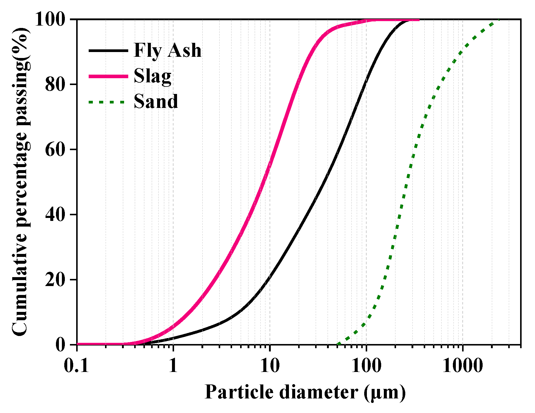
2.1. Raw Materials and Sample Preparation
2.2. Rheological Tests for AAFS Mortar
2.2.1. Dynamic Test
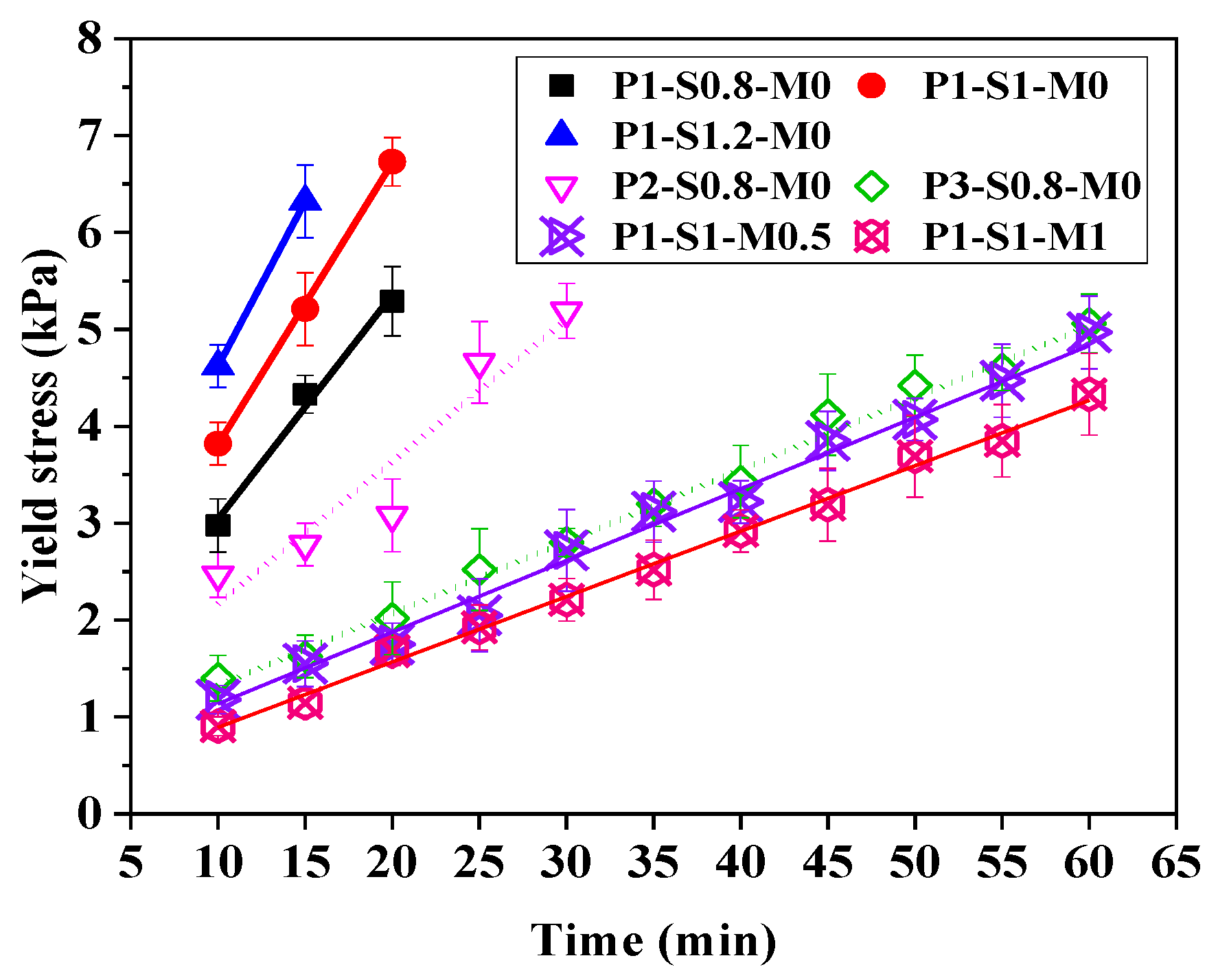
2.2.2. Static Test
2.3. Printability Tests
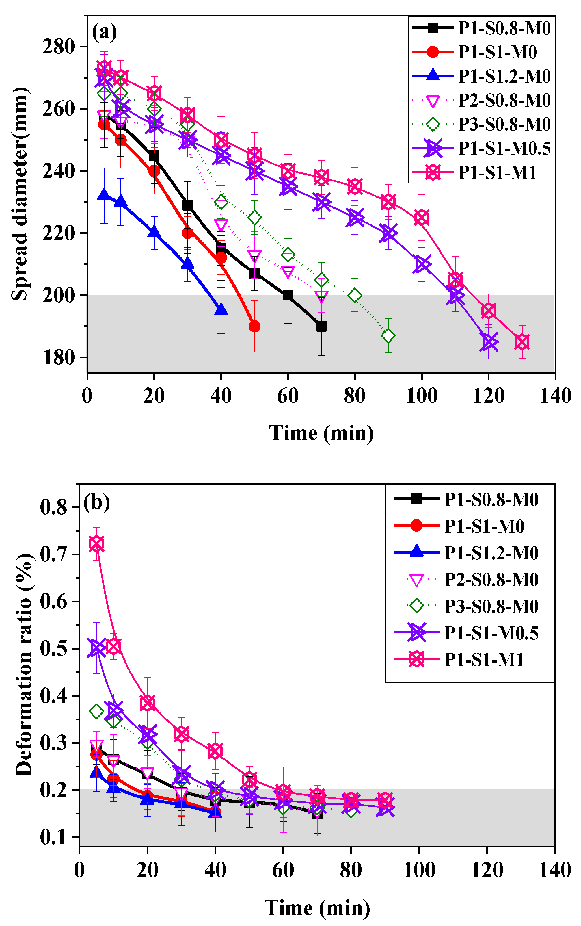
2.3.1. Flow Table Test
2.3.2. Buildability Test
2.4. Preparation of 3D-AAFS Mortar Specimen
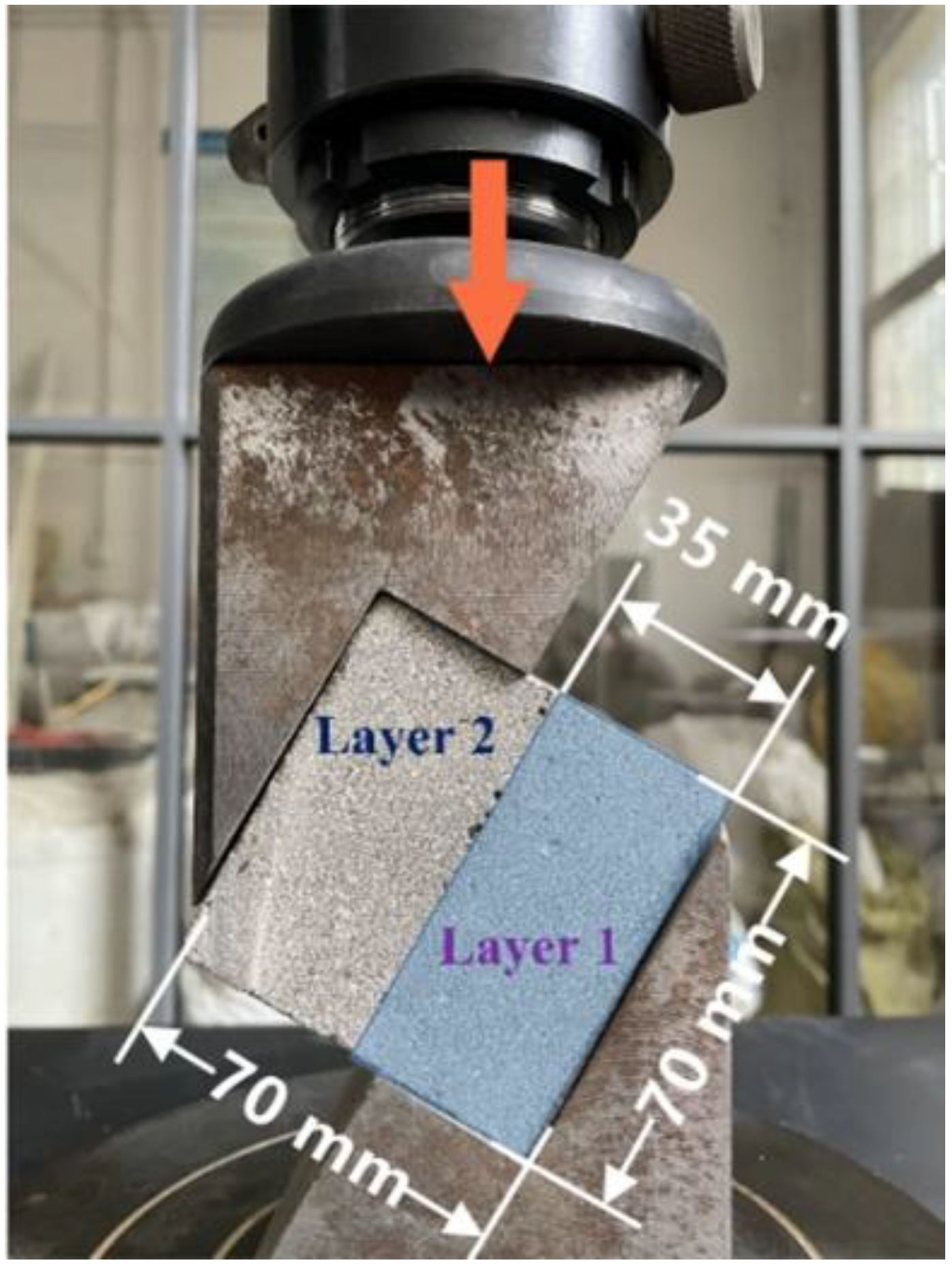
2.5. Interlayer Bond Strength Test
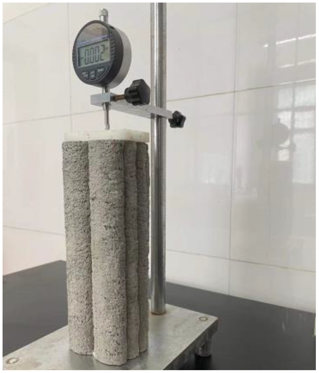
2.6. Drying Shrinkage
3. Results and Discussion
3.1. Rheological Behavior
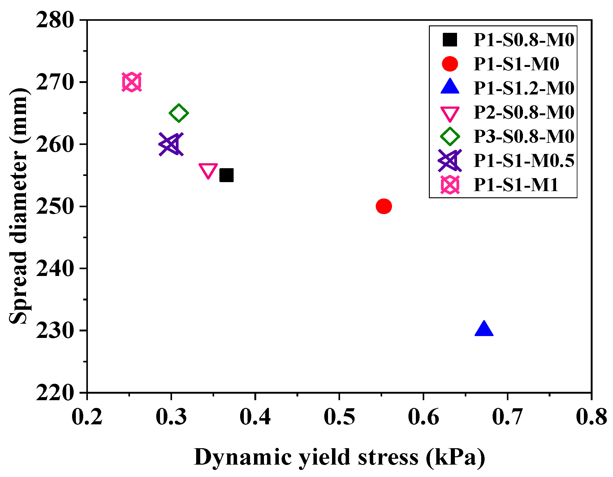
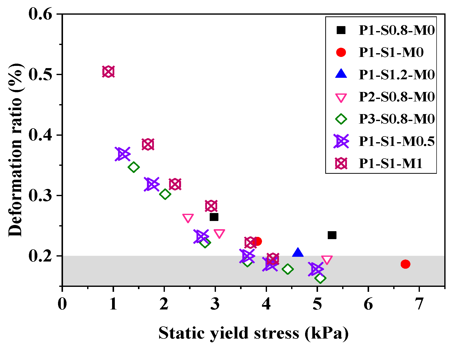
3.2. Printability
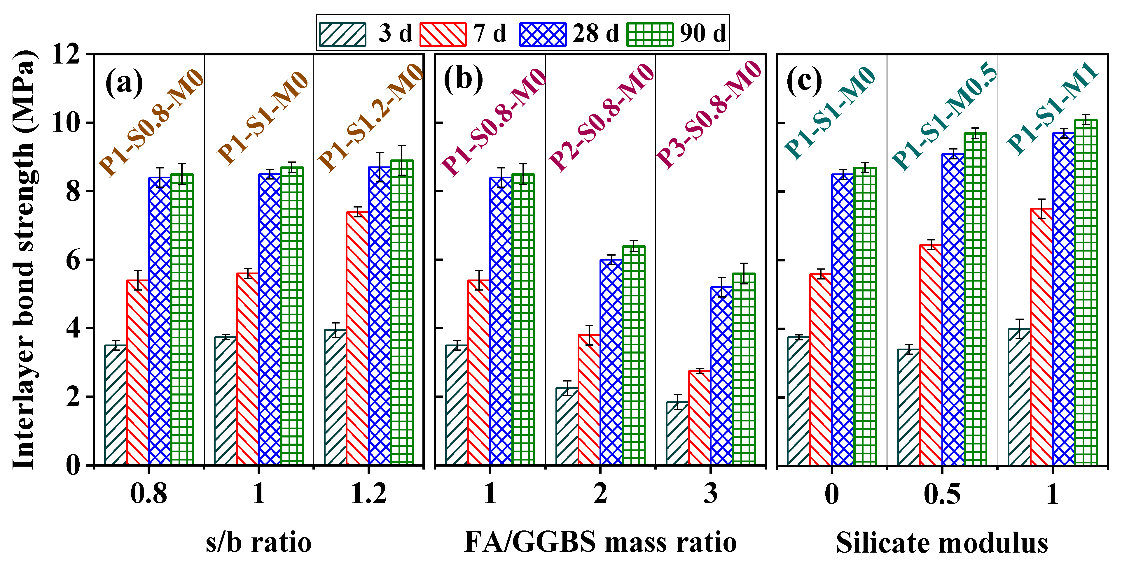
3.3. Interlayer Bond Strength
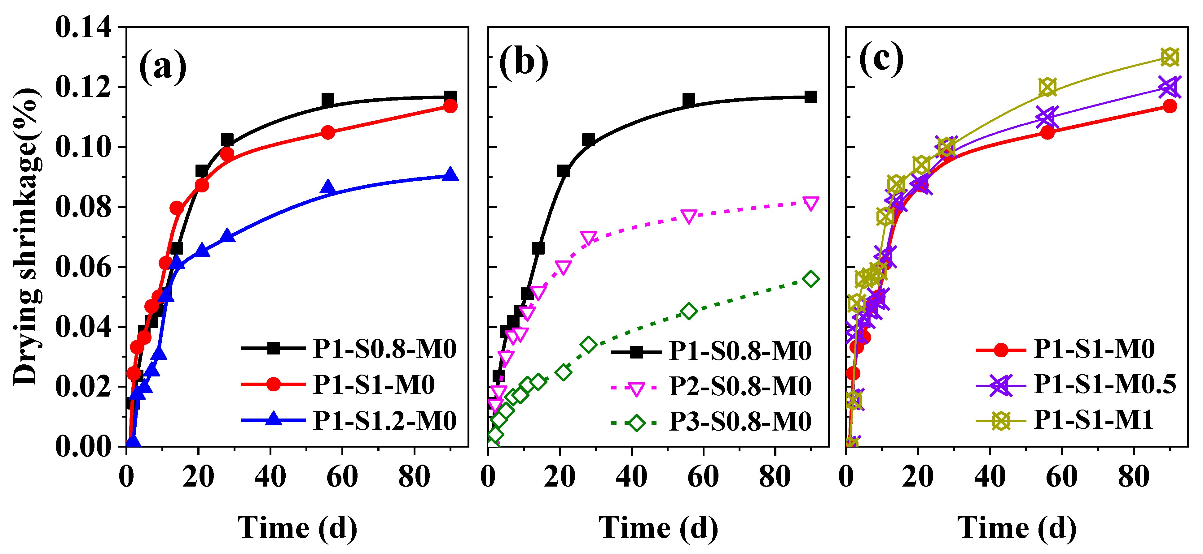
3.4. Drying Shrinkage
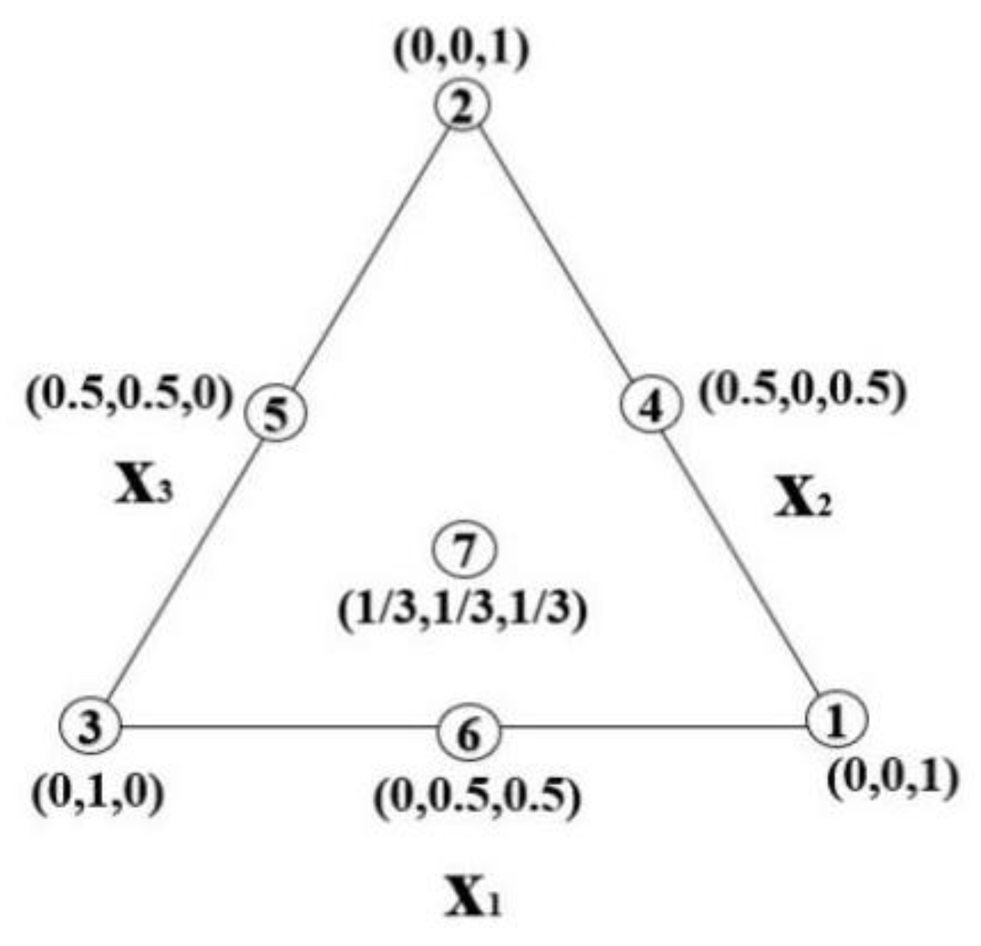
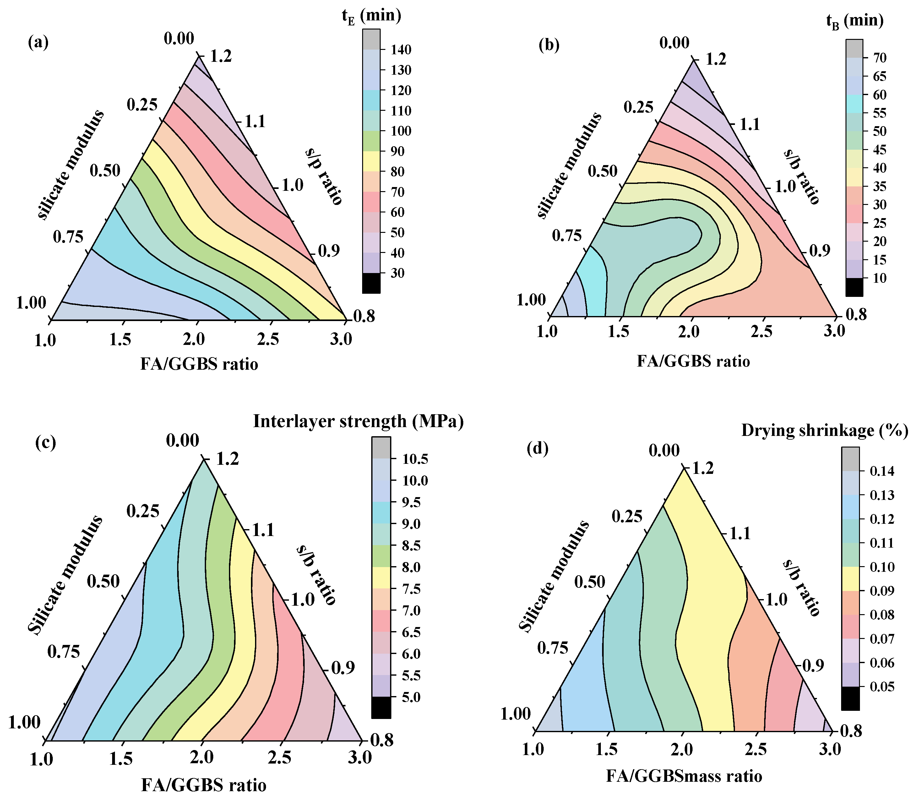
3.5. Mixture Design of 3D-AAFS Mortar Using the Simplex Centroid Design Method
4. Conclusions
- (1)
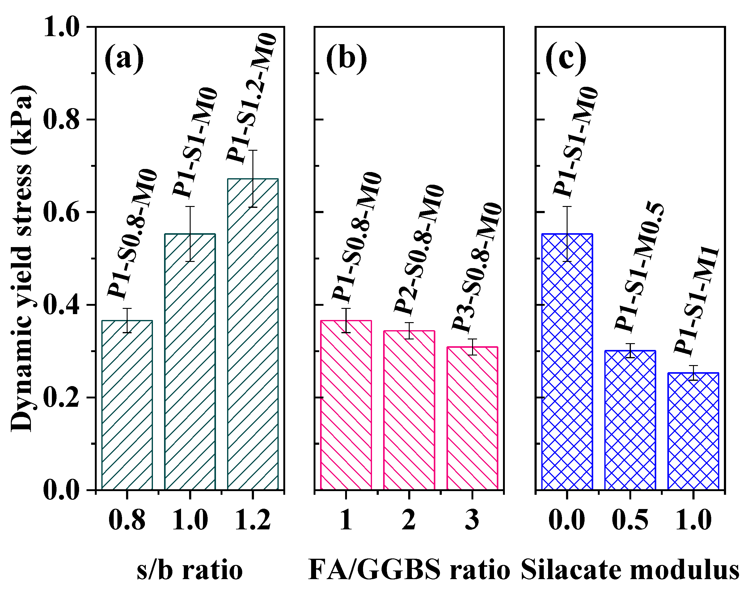
- The composition of alkali-activated fly ash/slag (AAFS) mortar exerts a tremendous influence on the printability of AAFS mortar, which relates closely to the rheological properties. The printability of AAFS mortar relates closely to the rheological properties. The increase in the s/b ratio enlarges the dynamic yield stress and accelerates the structural buildup of mortar, resulting in a faster loss rate of extrudability and a quicker growth rate of buildability. Conversely, increasing the FA/GGBS mass ratio or the silicate modulus reduces both the dynamic yield stress and structuration rate, which extends the duration time of extrudability and slows down the development of buildability. The printability of AAFS mortar is most sensitive to the silicate modulus of the activator.
- (2)
- The hardened-state properties of 3D-printed AAFS mortar also depend on its mix proportion. Increasing the s/b ratio is conducive to improving the interlayer bond strength and diminishing the drying shrinkage. The rise in the FA/GGBS mass ratio weakens the interlayer bond strength and reduces the drying shrinkage. The use of an activator with a larger silicate modulus is beneficial to the interlayer bond strength, but it causes a slightly larger drying shrinkage.
- (3)
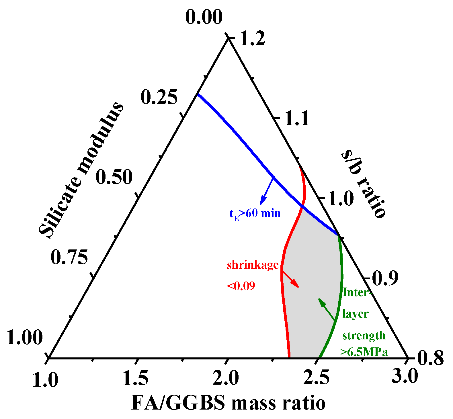
- A simple centroid design method was developed for mix proportioning of extrusion-based 3D-printed AAFS mortar for the first time, which took printability, interlayer bond strength, and drying shrinkage into consideration at the same time. By restricting the fresh-state and hardened-state requirements, the optimum mix proportion of 3D-AAFS mortar can be obtained using this method.
Author Contributions
Funding
Institutional Review Board Statement
Informed Consent Statement
Data Availability Statement
Conflicts of Interest
References
- DePalma, K.; Walluk, M.; Murtaugh, A.; Hilton, J.; McConky, S.; Hilton, B. Assessment of 3D printing using fused deposition modeling and selective laser sintering for a circular economy. J. Clean. Prod. 2020, 264, 121567. [Google Scholar] [CrossRef]
- Peeters, B.; Kiratli, N.; Semeijn, J. A barrier analysis for distributed recycling of 3D printing waste: Taking the maker movement perspective. J. Clean. Prod. 2019, 241, 118313. [Google Scholar] [CrossRef]
- Goulas, A.; Harris, R.A.; Friel, R. Additive manufacturing of physical assets by using ceramic multicomponent extra-terrestrial materials. Addit. Manuf. 2016, 10, 36–42. [Google Scholar] [CrossRef] [Green Version]
- Powell, D.; Rennie, A.E.; Geekie, L.; Burns, N. Understanding powder degradation in metal additive manufacturing to allow the upcycling of recycled powders. J. Clean. Prod. 2020, 268, 122077. [Google Scholar] [CrossRef]
- Govindharaj, M.; Roopavath, U.K.; Rath, S.N. Valorization of discarded Marine Eel fish skin for collagen extraction as a 3D printable blue biomaterial for tissue engineering. J. Clean. Prod. 2019, 230, 412–419. [Google Scholar] [CrossRef]
- Giudice, F.; Barbagallo, R.; Fargione, G. A Design for Additive Manufacturing approach based on process energy efficiency: Electron beam melted components. J. Clean. Prod. 2020, 290, 125185. [Google Scholar] [CrossRef]
- Meurisse, A.; Makaya, A.; Willsch, C.; Sperl, M. Solar 3D printing of lunar regolith. Acta Astronaut. 2018, 152, 800–810. [Google Scholar] [CrossRef]
- Alhumayani, H.; Gomaa, M.; Soebarto, V.; Jabi, W. Environmental assessment of large-scale 3D printing in construction: A comparative study between cob and concrete. J. Clean. Prod. 2020, 270, 122463. [Google Scholar] [CrossRef]
- Weng, Y.; Li, M.; Ruan, S.; Wong, T.N.; Tan, M.J.; Yeong, K.L.O.; Qian, S. Comparative economic, environmental and productivity assessment of a concrete bathroom unit fabricated through 3D printing and a precast approach. J. Clean. Prod. 2020, 261, 121245. [Google Scholar] [CrossRef]
- Panda, B.; Unluer, C.; Tan, M.-J. Extrusion and rheology characterization of geopolymer nanocomposites used in 3D printing. Compos. Part B Eng. 2019, 176, 107290. [Google Scholar] [CrossRef]
- Panda, B.; Singh, G.B.; Unluer, C.; Tan, M.-J. Synthesis and characterization of one-part geopolymers for extrusion based 3D concrete printing. J. Clean. Prod. 2019, 220, 610–619. [Google Scholar] [CrossRef]
- Han, Y.; Yang, Z.; Ding, T.; Xiao, J. Environmental and economic assessment on 3D printed buildings with recycled concrete. J. Clean. Prod. 2020, 278, 123884. [Google Scholar] [CrossRef]
- Ngo, T.D.; Kashani, A.; Imbalzano, G.; Nguyen, K.T.Q.; Hui, D. Additive manufacturing (3D printing): A review of materials, methods, applications and challenges. Compos. Part B Eng. 2018, 143, 172–196. [Google Scholar] [CrossRef]
- Chu, S.; Li, L.; Kwan, A. Development of extrudable high strength fiber reinforced concrete incorporating nano calcium carbonate. Addit. Manuf. 2020, 37, 101617. [Google Scholar] [CrossRef]
- Sun, C.; Xiang, J.; Xu, M.; He, Y.; Tong, Z.; Cui, X. 3D extrusion free forming of geopolymer composites: Materials modification and processing optimization. J. Clean. Prod. 2020, 258, 120986. [Google Scholar] [CrossRef]
- Panda, B.; Paul, S.C.; Hui, L.J.; Tay, Y.W.D.; Tan, M.J. Additive manufacturing of geopolymer for sustainable built environment. J. Clean. Prod. 2017, 167, 281–288. [Google Scholar] [CrossRef]
- Le, T.T.; Austin, S.A.; Lim, S.; Buswell, R.A.; Gibb, A.G.F.; Thorpe, T. Mix design and fresh properties for high-performance printing concrete. Mater. Struct. 2012, 45, 1221–1232. [Google Scholar] [CrossRef] [Green Version]
- Sun, J.; Huang, Y.; Aslani, F.; Ma, G. Properties of a double-layer EMW-absorbing structure containing a graded nano-sized absorbent combing extruded and sprayed 3D printing. Constr. Build. Mater. 2020, 261, 120031. [Google Scholar] [CrossRef]
- Maciel, V.G.; Wales, D.J.; Seferin, M.; Sans, V. Environmental performance of 3D-Printing polymerisable ionic liquids. J. Clean. Prod. 2019, 214, 29–40. [Google Scholar] [CrossRef]
- Schutter, G.D.; Lesage, K.; Mechtcherine, V.; Nerella, V.N.; Habert, G.; Agusti-Juan, I. Vision of 3D printing with concrete-technical, economic and environmental potentials. Cem. Concr. Res. 2018, 112, 25–36. [Google Scholar] [CrossRef]
- Xu, J.; Wang, K.; Sheng, H.; Gao, M.; Zhang, S.; Tan, J. Energy efficiency optimization for ecological 3D printing based on adaptive multi-layer customization. J. Clean. Prod. 2019, 245, 118826. [Google Scholar] [CrossRef]
- Asprone, D.; Auricchio, F.; Menna, C.; Mercuri, V. 3D printing of reinforced concrete elements: Technology and design approach. Constr. Build. Mater. 2018, 165, 218–231. [Google Scholar] [CrossRef]
- Mellin, P.; Jönsson, C.; Åkermo, M.; Fernberg, P.; Nordenberg, E.; Brodin, H.; Strondl, A. Nano-sized by-products from metal 3D printing, composite manufacturing and fabric production. J. Clean. Prod. 2016, 139, 1224–1233. [Google Scholar] [CrossRef]
- Sun, J.; Aslani, F.; Lu, J.; Wang, L.; Huang, Y.; Ma, G. Fibre-reinforced lightweight engineered cementitious composites for 3D concrete printing. Ceram. Int. 2021, 47, 27107–27121. [Google Scholar] [CrossRef]
- Buswell, R.; Soar, R.; Gibb, A.; Thorpe, A. Freeform Construction: Mega-scale Rapid Manufacturing for construction. Autom. Constr. 2007, 16, 224–231. [Google Scholar] [CrossRef] [Green Version]
- Perrot, A.; Rangeard, D.; Pierre, A. Structural built-up of cement-based materials used for 3D-printing extrusion techniques. Mater. Struct. 2015, 49, 1213–1220. [Google Scholar] [CrossRef]
- Soltan, D.G.; Li, V.C. A self-reinforced cementitious composite for building-scale 3D printing. Cem. Concr. Compos. 2018, 90, 1–13. [Google Scholar] [CrossRef]
- Paul, S.C.; Tay, Y.W.D.; Panda, B.; Tan, M.J. Fresh and hardened properties of 3D printable cementitious materials for building and construction. Arch. Civ. Mech. Eng. 2018, 18, 311–319. [Google Scholar] [CrossRef]
- Zhang, Y.; Zhang, Y.S.; She, W.; Yang, L.; Lin, G.J.; Yang, Y.G. Rheological and harden properties of the high-thixotropy 3D printing concrete. Constr. Build. Mater. 2019, 201, 278–285. [Google Scholar] [CrossRef]
- Zhang, D.-W.; Wang, D.-M.; Lin, X.-Q.; Zhang, T. The study of the structure rebuilding and yield stress of 3D printing geopolymer pastes. Constr. Build. Mater. 2018, 184, 575–580. [Google Scholar] [CrossRef]
- Ma, G.; Li, Z.; Wang, L. Printable properties of cementitious material containing copper tailings for extrusion based 3D printing. Constr. Build. Mater. 2018, 162, 613–627. [Google Scholar] [CrossRef]
- Zhang, Y.; Zhang, Y.; Liu, G.; Yang, Y.; Wu, M.; Pang, B. Fresh properties of a novel 3D printing concrete ink. Constr. Build. Mater. 2018, 174, 263–271. [Google Scholar] [CrossRef]
- Yuan, Q.; Li, Z.; Zhou, D.; Huang, T.; Huang, H.; Jiao, D.; Shi, C. A feasible method for measuring the buildability of fresh 3D printing mortar. Constr. Build. Mater. 2019, 227, 116600. [Google Scholar] [CrossRef]
- Panda, B.; Tan, M.-J. Experimental study on mix proportion and fresh properties of fly ash based geopolymer for 3D concrete printing. Ceram. Int. 2018, 44, 10258–10265. [Google Scholar] [CrossRef]
- Kazemian, A.; Yuan, X.; Cochran, E.; Khoshnevis, B. Cementitious materials for construction-scale 3D printing: Laboratory testing of fresh printing mixture. Constr. Build. Mater. 2017, 145, 639–647. [Google Scholar] [CrossRef]
- Muthukrishnan, S.; Ramakrishnan, S.; Sanjayan, J. Effect of microwave heating on interlayer bonding and buildability of geopolymer 3D concrete printing. Constr. Build. Mater. 2020, 265, 120786. [Google Scholar] [CrossRef]
- Muthukrishnan, S.; Ramakrishnan, S.; Sanjayan, J. Effect of alkali reactions on the rheology of one-part 3D printable geopolymer concrete. Cem. Concr. Compos. 2020, 116, 103899. [Google Scholar] [CrossRef]
- Nerella, V.; Beigh, M.; Fataei, S.; Mechtcherine, V. Strain-based approach for measuring structural build-up of cement pastes in the context of digital construction. Cem. Concr. Res. 2018, 115, 530–544. [Google Scholar] [CrossRef]
- Shi, C.; Jimenez, A.F.; Palomo, A. New cements for the 21st century: The pursuit of an alternative to Portland cement. Cem. Concr. Res. 2011, 41, 750–763. [Google Scholar] [CrossRef]
- Environment, U.; Scrivener, K.L.; John, V.M.; Gartner, E.M. Eco-efficient cements: Potential economically viable solutions for a low-CO2 cement-based materials industry. Cem. Concr. Res. 2018, 114, 2–26. [Google Scholar] [CrossRef]
- Schneider, M.; Romer, M.; Tschudin, M.; Bolio, H. Sustainable cement production—present and future. Cem. Concr. Res. 2011, 41, 642–650. [Google Scholar] [CrossRef]
- Damtoft, J.S.; Lukasik, J.; Herfort, D.; Sorrentino, D.; Gartner, E.M. Sustainable development and climate change initiatives. Cem. Concr. Res. 2008, 38, 115–127. [Google Scholar] [CrossRef]
- Atiş, C.D.; Bilim, C.; Çelik, Ö.; Karahan, O. Influence of activator on the strength and drying shrinkage of alkali-activated slag mortar. Constr. Build. Mater. 2009, 23, 548–555. [Google Scholar] [CrossRef]
- Kani, E.N.; Allahverdi, A.; Provis, J. Efflorescence control in geopolymer binders based on natural pozzolan. Cem. Concr. Compos. 2012, 34, 25–33. [Google Scholar] [CrossRef]
- Alghamdi, H.; Nair, S.A.; Neithalath, N. Insights into material design, extrusion rheology, and properties of 3D-printable alkali-activated fly ash-based binders. Mater. Des. 2019, 167, 107634. [Google Scholar] [CrossRef]
- Xia, M.; Sanjayan, J. Method of formulating geopolymer for 3D printing for construction applications. Mater. Des. 2016, 110, 382–390. [Google Scholar] [CrossRef]
- Xia, M.; Nematollahi, B.; Sanjayan, J. Printability, accuracy and strength of geopolymer made using powder-based 3D printing for construction applications. Autom. Constr. 2019, 101, 179–189. [Google Scholar] [CrossRef]
- Xia, M.; Sanjayan, J. Methods of enhancing strength of geopolymer produced from powder-based 3D printing process. Mater. Lett. 2018, 227, 281–283. [Google Scholar] [CrossRef]
- Panda, B.; Unluer, C.; Tan, M.J. Investigation of the rheology and strength of geopolymer mixtures for extrusion-based 3D printing. Cem. Concr. Compos. 2018, 94, 307–314. [Google Scholar] [CrossRef]
- Chougan, M.; Ghaffar, S.H.; Jahanzat, M.; Albar, A.; Mujaddedi, N.; Swash, R. The influence of nano-additives in strengthening mechanical performance of 3D printed multi-binder geopolymer composites. Constr. Build. Mater. 2020, 250, 118928. [Google Scholar] [CrossRef]
- Sanjayan, J.G.; Nematollahi, B.; Xia, M.; Marchment, T. Effect of surface moisture on inter-layer strength of 3D printed concrete. Constr. Build. Mater. 2018, 172, 468–475. [Google Scholar] [CrossRef]
- El Sakka, F.; Assaad, J.J.; Hamzeh, F.R.; Nakhoul, C. Thixotropy and interfacial bond strengths of polymer-modified printed mortars. Mater. Struct. 2019, 52, 79. [Google Scholar] [CrossRef]
- Zareiyana, B.; Khoshnevis, B. Interlayer adhesion and strength of structures in Contour Crafting-Effects of aggregate size, extrusion rate, and layer thickness. Autom. Constr. 2017, 81, 112–121. [Google Scholar] [CrossRef]
- Diab, A.; Abd, E.; Mohamed, R. Slant shear bond strength between self compacting concrete and old concrete. Constr. Build. Mater. 2017, 130, 73–82. [Google Scholar] [CrossRef]
- Al-Qutaifi, S.; Nazari, A.; Bagheri, A. Mechanical properties of layered geopolymer structures applicable in concrete 3D-printing. Constr. Build. Mater. 2018, 176, 690–699. [Google Scholar] [CrossRef]
- Nematollahi, B.; Xia, M.; Sanjayan, J.; Vijay, P. Effect of Type of Fiber on Inter-Layer Bond and Flexural Strengths of Extrusion-Based 3D Printed Geopolymer. Mater. Sci. Forum 2018, 939, 155–162. [Google Scholar] [CrossRef]
- Lim, J.H.; Panda, B.; Pham, Q.-C. Improving flexural characteristics of 3D printed geopolymer composites with in-process steel cable reinforcement. Constr. Build. Mater. 2018, 178, 32–41. [Google Scholar] [CrossRef]
- Panda, B.; Paul, S.C.; Mohamed, N.A.N.; Tay, Y.W.D.; Tan, M.J. Measurement of tensile bond strength of 3D printed geopolymer mortar. Measurement 2018, 113, 108–116. [Google Scholar] [CrossRef]
- Collins, F.; Sanjayan, J. Effect of pore size distribution on drying shrinking of alkali-activated slag concrete. Cem. Concr. Res. 2000, 30, 1401–1406. [Google Scholar] [CrossRef]
- Si, R.; Dai, Q.; Guo, S.; Wang, J. Mechanical property, nanopore structure and drying shrinkage of metakaolin-based geopolymer with waste glass powder. J. Clean. Prod. 2019, 242, 118502. [Google Scholar] [CrossRef]
- GB/T 1596-2017; Standard for Fly Ash Used for Cement and Concrete. Ministry of Housing and Urban-Rural Development: Beijing, China, 2017.
- GB/T 18046-2017; Standard for Ground Granulated Blast Furnace Slag Used for Cement, Mortar and Concrete. Ministry of Housing and Urban-Rural Development: Beijing, China, 2017.
- Yuan, Q.; Zhou, D.; Khayat, K.; Feys, D.; Shi, C. On the measurement of evolution of structural build-up of cement paste with time by static yield stress test vs. small amplitude oscillatory shear test. Cem. Concr. Res. 2017, 99, 183–189. [Google Scholar] [CrossRef]
- Roussel, N. Thixotropy model for fresh fluid concretes: Theory, validation and applications. Cem. Concr. Res. 2006, 36, 1797–1806. [Google Scholar] [CrossRef]
- ASTM C230; Standard Specification for Flow Table for Use in Tests of Hydraulic Cement. ASTM International: West Conshohocken, PA, USA, 2003.
- Tay, Y.W.D.; Qian, Y.; Tan, M.-J. Printability region for 3D concrete printing using slump and slump flow test. Compos. Part B Eng. 2019, 174, 106968. [Google Scholar] [CrossRef]
- Chen, Y.; He, S.; Zhang, Y.; Wan, Z.; Çopuroğlu, O.; Schlangen, E. 3D printing of calcined clay-limestone-based cementitious materials. Cem. Concr. Res. 2021, 149, 106553. [Google Scholar] [CrossRef]
- Xu, Y.; Yuan, Q.; Li, Z.; Shi, C.; Wu, Q.; Huang, Y. Correlation of interlayer properties and rheological behaviors of 3DPC with various printing time intervals. Addit. Manuf. 2021, 47, 102327. [Google Scholar] [CrossRef]
- Yao, H.; Xie, Z.; Li, Z.; Huang, C.; Yuan, Q.; Zheng, X. The relationship between the rheological behavior and interlayer bonding properties of 3D printing cementitious materials with the addition of attapulgite. Constr. Build. Mater. 2021, 316, 125809. [Google Scholar] [CrossRef]
- ASTM C157; Standard Test Method for Length Change of Hardened Hydraulic-Cement Mortar and Concrete. ASTM International: West Conshohocken, PA, USA, 2010.
- Jiao, D.; Shi, C.; Yuan, Q.; An, X.; Liu, Y.; Li, H. Effect of constituents on rheological properties of fresh concrete—A review. Cem. Concr. Compos. 2017, 83, 146–159. [Google Scholar] [CrossRef]
- Lu, C.; Zhang, Z.; Shi, C.; Li, N.; Jiao, D.; Yuan, Q. Rheology of alkali-activated materials: A review. Cem. Concr. Compos. 2021, 121, 104061. [Google Scholar] [CrossRef]
- Yuan, Q.; Huang, Y.L.; Huang, T.J.; Yao, H.; Wu, Q.H. Effects of activator on the rheological properties of alkali-activated slag-fly ahs pastes. J. Cent. South Univ. 2022, 29, 282–295. [Google Scholar] [CrossRef]
- Dai, X.; Aydın, S.; Yardımcı, M.Y.; Lesage, K.; De Schutter, G. Effects of activator properties and GGBFS/FA ratio on the structural build-up and rheology of AAC. Cem. Concr. Res. 2020, 138, 106253. [Google Scholar] [CrossRef]
- Puertas, F.; Martinez-Ramirez, S.; Alonso, S.; Vázquez, T. Alkali-activated fly ash/slag cements: Strength behaviour and hydration products. Cem. Concr. Res. 2000, 30, 1625–1632. [Google Scholar] [CrossRef]
- Chi, M.; Huang, R. Binding mechanism and properties of alkali-activated fly ash/slag mortars. Constr. Build. Mater. 2013, 40, 291–298. [Google Scholar] [CrossRef]
- Arbi, K.; Nedeljković, M.; Zuo, Y.; Ye, G. A Review on the Durability of Alkali-Activated Fly Ash/Slag Systems: Advances, Issues, and Perspectives. Ind. Eng. Chem. Res. 2016, 55, 5439–5453. [Google Scholar] [CrossRef] [Green Version]
- Lee, N.; Jang, J.; Lee, H. Shrinkage characteristics of alkali-activated fly ash/slag paste and mortar at early ages. Cem. Concr. Compos. 2014, 53, 239–248. [Google Scholar] [CrossRef]
- Jiao, D.; Shi, C.; Yuan, Q.; An, X.; Liu, Y. Mixture design of concrete using simplex centroid design method. Cem. Concr. Compos. 2018, 89, 76–88. [Google Scholar] [CrossRef]
- Zhang, C.; Nerella, V.N.; Krishna, A.; Wang, S.; Zhang, Y.; Mechtcherine, V.; Banthia, N. Mix design concepts for 3D printable concrete: A review. Cem. Concr. Compos. 2021, 122, 104155. [Google Scholar] [CrossRef]
- Chen, Y.; Jansen, K.; Zhang, H.; Rodriguez, C.R.; Gan, Y.; Copuroglu, O.; Schlangen, E. Effect of printing parameters on interlayer bond strength of 3D printed limestone-calcined clay-based cementitious materials: An experimental and numerical study. Constr. Build. Mater. 2020, 262, 120094. [Google Scholar] [CrossRef]
- Liu, Z.; Wang, Z.; Wang, L.; Zhao, X. Interlayer Bond Strength of 3D Printing Cement Paste by Cross-Bonded Method. J. Chin. Ceram. Soc. 2019, 47, 648–652. [Google Scholar]
- Singh, B.; Rahman, M.; Paswan, R.; Bhattacharyya, S. Effect of activator concentration on the strength, ITZ and drying shrinkage of fly ash/slag geopolymer concrete. Constr. Build. Mater. 2016, 118, 171–179. [Google Scholar] [CrossRef]


| SiO2 | CaO | Al2O3 | Fe2O3 | MgO | SO3 | K2O | Na2O | LOI | |
|---|---|---|---|---|---|---|---|---|---|
| GGBS | 32.84 | 38.92 | 13.33 | 0.30 | 9.67 | 1.47 | 0.83 | 0.24 | 2.4 |
| FA | 59.38 | 2.16 | 29.74 | 3.80 | 1.36 | 0.83 | 0.32 | 0.42 | 1.99 |
| Sample | Mass Fraction (wt.%) | FA/GGBS Mass Ratio | s/b Ratio | Silicate Modulus | Alkali Dosage (Na2O wt.%) | ||
|---|---|---|---|---|---|---|---|
| FA | GGBS | Sand | |||||
| P1-S0.8-M0 | 27.8 | 27.8 | 44.4 | 1 | 0.8 | 0 | 3.5 |
| P1-S1-M0 | 25.0 | 25.0 | 50.0 | 1 | 1.0 | 0 | 3.5 |
| P1-S1.2-M0 | 22.7 | 22.7 | 54.5 | 1 | 1.2 | 0 | 3.5 |
| P2-S0.8-M0 | 37.0 | 18.5 | 44.4 | 2 | 0.8 | 0 | 3.5 |
| P3-S0.8-M0 | 41.7 | 13.9 | 44.4 | 3 | 0.8 | 0 | 3.5 |
| P1-S1-M0.5 | 25.0 | 25.0 | 50.0 | 1 | 1 | 0.5 | 3.5 |
| P1-S1-M1 | 25.0 | 25.0 | 50.0 | 1 | 1 | 1 | 3.5 |
| P1-S0.8-M1 | 27.8 | 27.8 | 44.4 | 1 | 0.8 | 1 | 3.5 |
| P2-S0.8-M0.5 | 37.0 | 18.5 | 44.4 | 2 | 0.8 | 0.5 | 3.5 |
| P2-S1-M0 | 33.3 | 16.7 | 50.0 | 2 | 1 | 0 | 3.5 |
| P1.7-S1.1-M0.3 | 30.0 | 17.6 | 52.4 | 1.7 | 1.1 | 0.3 | 3.5 |
| Sample | ts,0 (kPa) | Athix (kPa/min) | R2 |
|---|---|---|---|
| P1-S0.8-M0 | 0.728 | 0.233 | 0.926 |
| P1-S1-M0 | 1.021 | 0.291 | 0.987 |
| P1-S1.2-M0 | 1.220 | 0.342 | 0.993 |
| P2-S0.8-M0 | 0.704 | 0.147 | 0.914 |
| P3-S0.8-M0 | 0.583 | 0.0742 | 0.991 |
| P1-S1-M0.5 | 0.394 | 0.0739 | 0.979 |
| P1-S1-M1 | 0.218 | 0.0675 | 0.969 |
| tE (min) | tB (min) | |
|---|---|---|
| P1-S0.8-M0 | 60 | 30 |
| P1-S1-M0 | 45 | 15 |
| P1-S1.2-M0 | 35 | 10 |
| P2-S0.8-M0 | 70 | 30 |
| P3-S0.8-M0 | 80 | 35 |
| P1-S1-M0.5 | 110 | 40 |
| P1-S1-M1 | 115 | 60 |
| Number in Figure 11 | Sample | Actual Value of Factors | Linear Substitution of Factors | ||||
|---|---|---|---|---|---|---|---|
| FA/GGBS Ratio (z1) | s/b Ratio (z2) | Ms (z3) | FA/GGBS Ratio (x1) | s/b Ratio (x2) | Ms (x3) | ||
| 1 | P1-S0.8-M1 | 1.0 | 0.8 | 1.0 | 0 | 0 | 1 |
| 2 | P3-S0.8-M0 | 3.0 | 0.8 | 0.0 | 1 | 0 | 0 |
| 3 | P1-S1.2-M0 | 1.0 | 1.2 | 0.0 | 0 | 1 | 0 |
| 4 | P2-S0.8-M0.5 | 2.0 | 0.8 | 0.5 | 0.5 | 0 | 0.5 |
| 5 | P2-S1-M0 | 2.0 | 1.0 | 0.0 | 0.5 | 0.5 | 0 |
| 6 | P1-S1-M0.5 | 1.0 | 1.0 | 0.5 | 0 | 0.5 | 0.5 |
| 7 | P1.7-S1.1-M0.3 | 1.7 | 1.1 | 0.3 | 1/3 | 1/3 | 1/3 |
| No. | Sample | tE (min) | tB (min) | Interlayer Bond Strength at 90 Days (MPa) | Drying Shrinkage at 90 Days (%) |
|---|---|---|---|---|---|
| 1 | P1-S0.8-M1 | 130 | 70 | 10.1 ± 0.07 | 0.135 ± 0.012 |
| 2 | P3-S0.8-M0 | 80 | 35 | 5.6 ± 0.07 | 0.056 ± 0.008 |
| 3 | P1-S1.2-M0 | 35 | 10 | 8.9 ± 0.07 | 0.0904 ± 0.005 |
| 4 | P2-S0.8-M0.5 | 135 | 30 | 7.4 ± 0.07 | 0.107 ± 0.010 |
| 5 | P2-S1-M0 | 55 | 20 | 6.7 ± 0.28 | 0.09 ± 0.006 |
| 6 | P1-S1-M0.5 | 110 | 40 | 9.7 ± 0.14 | 0.12 ± 0.011 |
| 7 | P1.7-S1.1-M0.3 | 80 | 55 | 8.8 ± 0.54 | 0.095 ± 0.008 |
Publisher’s Note: MDPI stays neutral with regard to jurisdictional claims in published maps and institutional affiliations. |
© 2022 by the authors. Licensee MDPI, Basel, Switzerland. This article is an open access article distributed under the terms and conditions of the Creative Commons Attribution (CC BY) license (https://creativecommons.org/licenses/by/4.0/).
Share and Cite
Yuan, Q.; Gao, C.; Huang, T.; Zuo, S.; Yao, H.; Zhang, K.; Huang, Y.; Liu, J. Factors Influencing the Properties of Extrusion-Based 3D-Printed Alkali-Activated Fly Ash-Slag Mortar. Materials 2022, 15, 1969. https://doi.org/10.3390/ma15051969
Yuan Q, Gao C, Huang T, Zuo S, Yao H, Zhang K, Huang Y, Liu J. Factors Influencing the Properties of Extrusion-Based 3D-Printed Alkali-Activated Fly Ash-Slag Mortar. Materials. 2022; 15(5):1969. https://doi.org/10.3390/ma15051969
Chicago/Turabian StyleYuan, Qiang, Chao Gao, Tingjie Huang, Shenghao Zuo, Hao Yao, Kai Zhang, Yanling Huang, and Jing Liu. 2022. "Factors Influencing the Properties of Extrusion-Based 3D-Printed Alkali-Activated Fly Ash-Slag Mortar" Materials 15, no. 5: 1969. https://doi.org/10.3390/ma15051969