
Tensile Performance of Headed Anchors in Steel Fiber Reinforced and Conventional Concrete in Uncracked and Cracked State


Abstract
:1. Introduction
1.1. General
1.2. Failure Load Prediction and Design in Unreinforced Concrete
1.3. Previous Research on Fastenings in SFRC
1.4. Current Design Proposals for Concrete Breakout Failure of Fastenings in SFRC
1.5. Objective of This Article
2. Materials and Methods
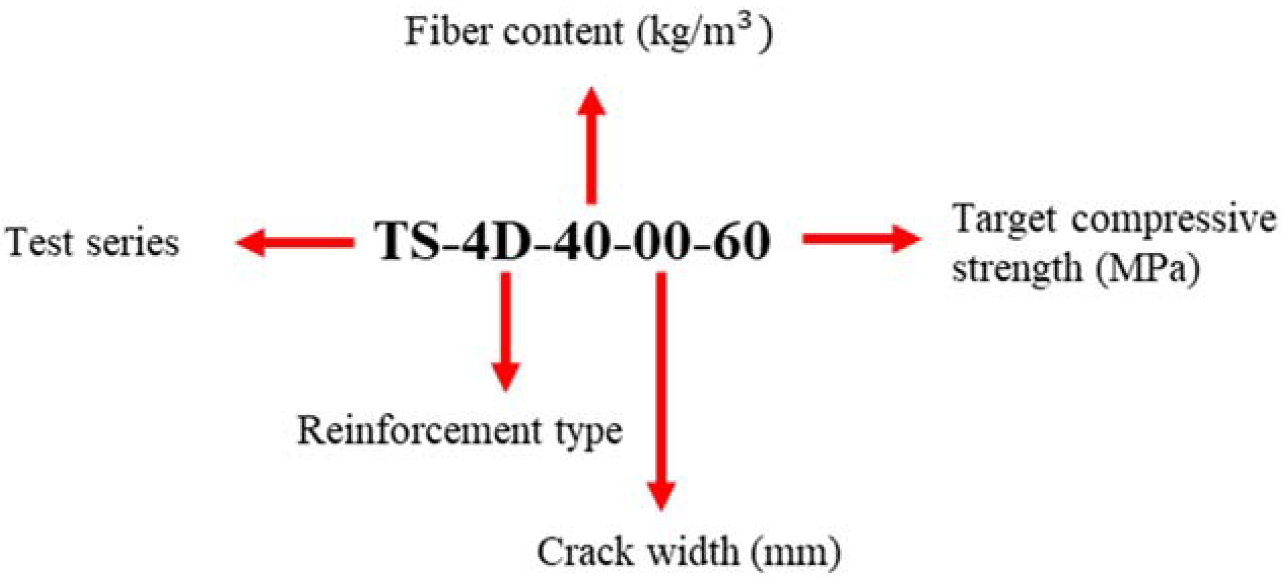
2.1. Overview of Test Program
2.2. Materials
2.2.1. Concrete
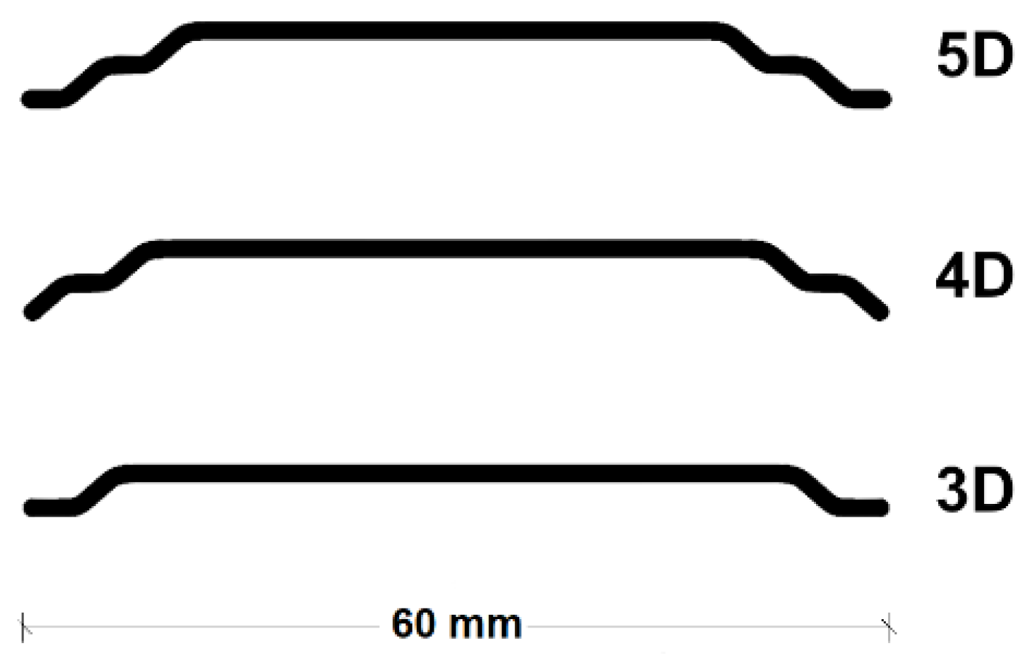
2.2.2. Fibers
2.2.3. Anchors
2.2.4. Material Testing
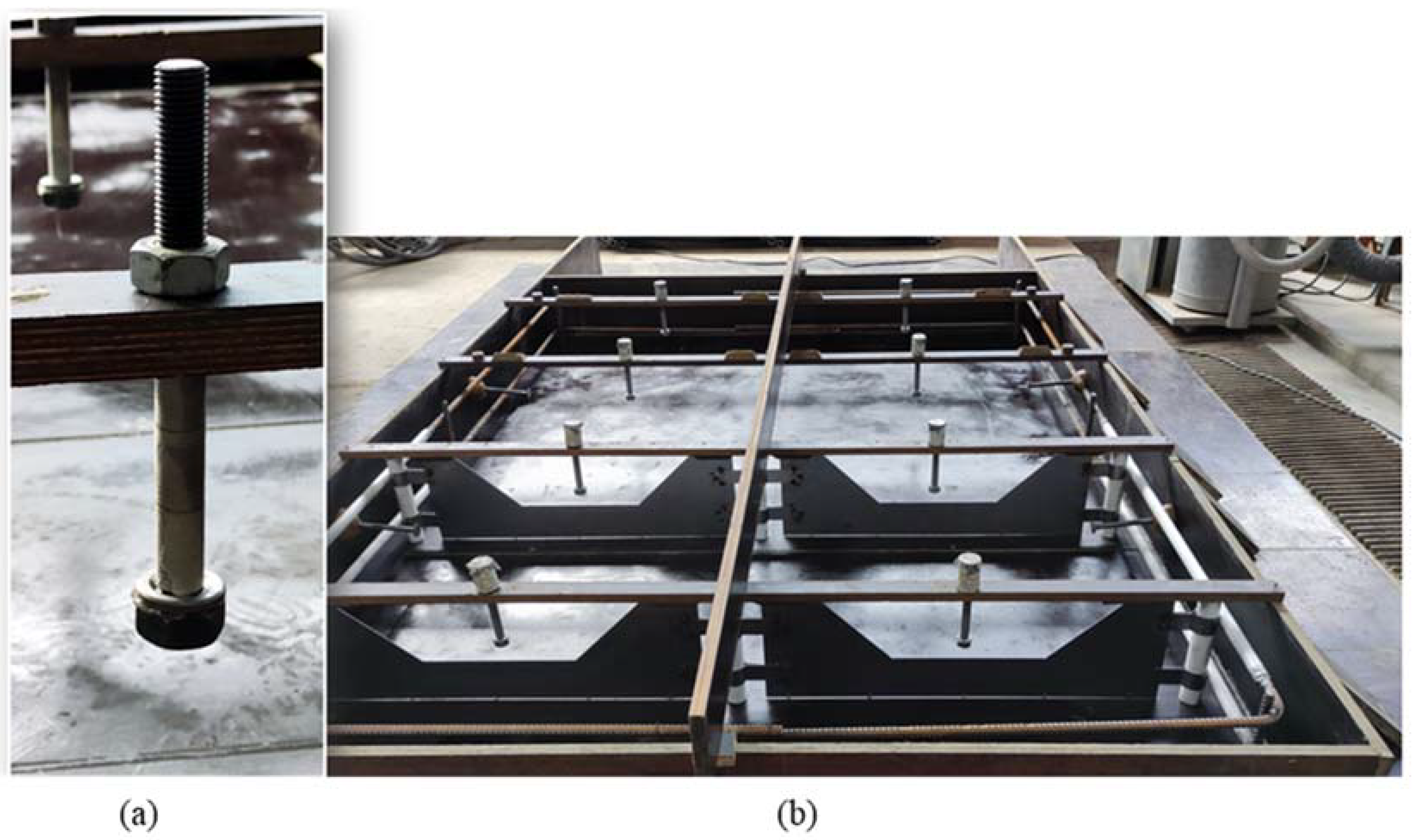
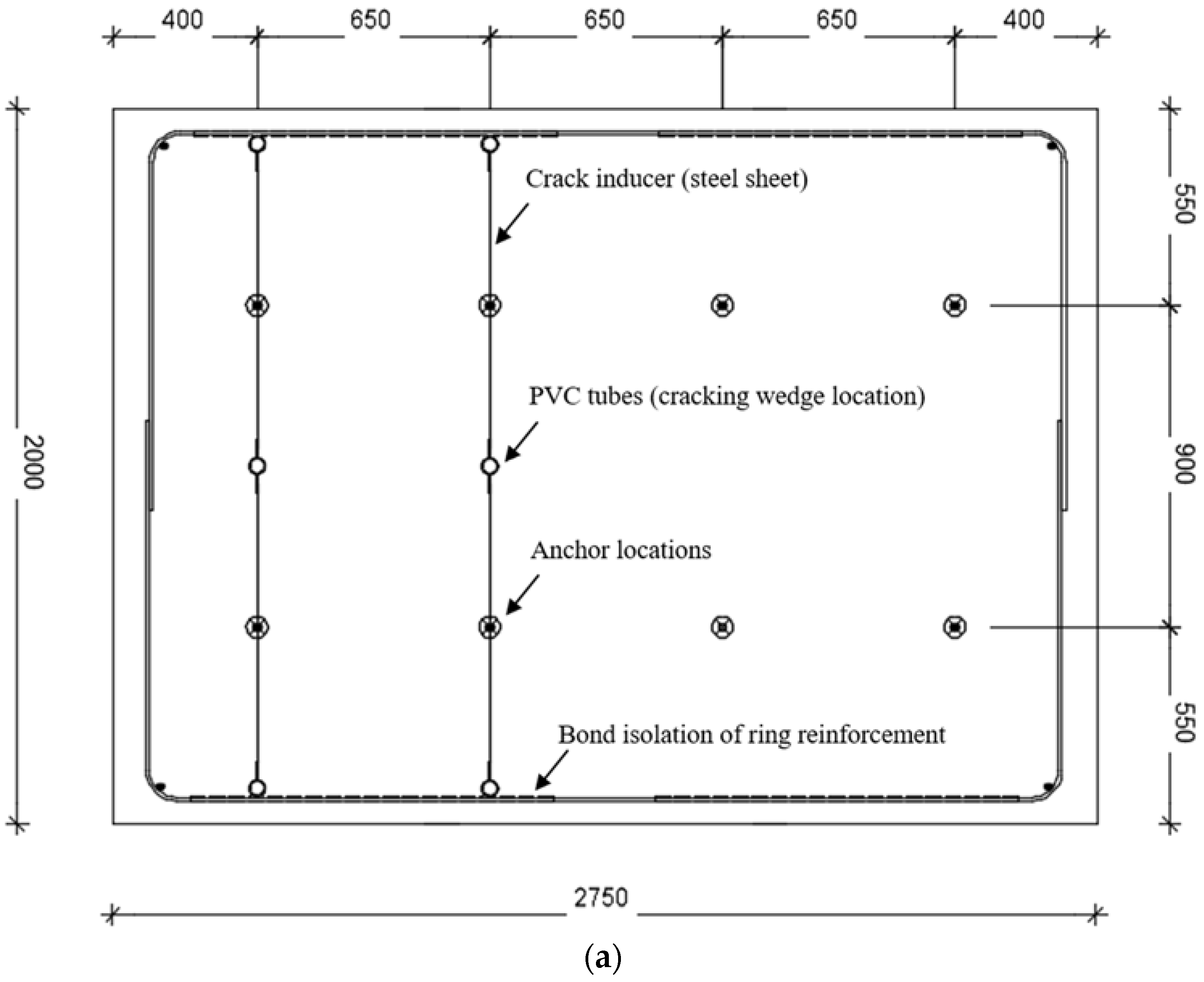
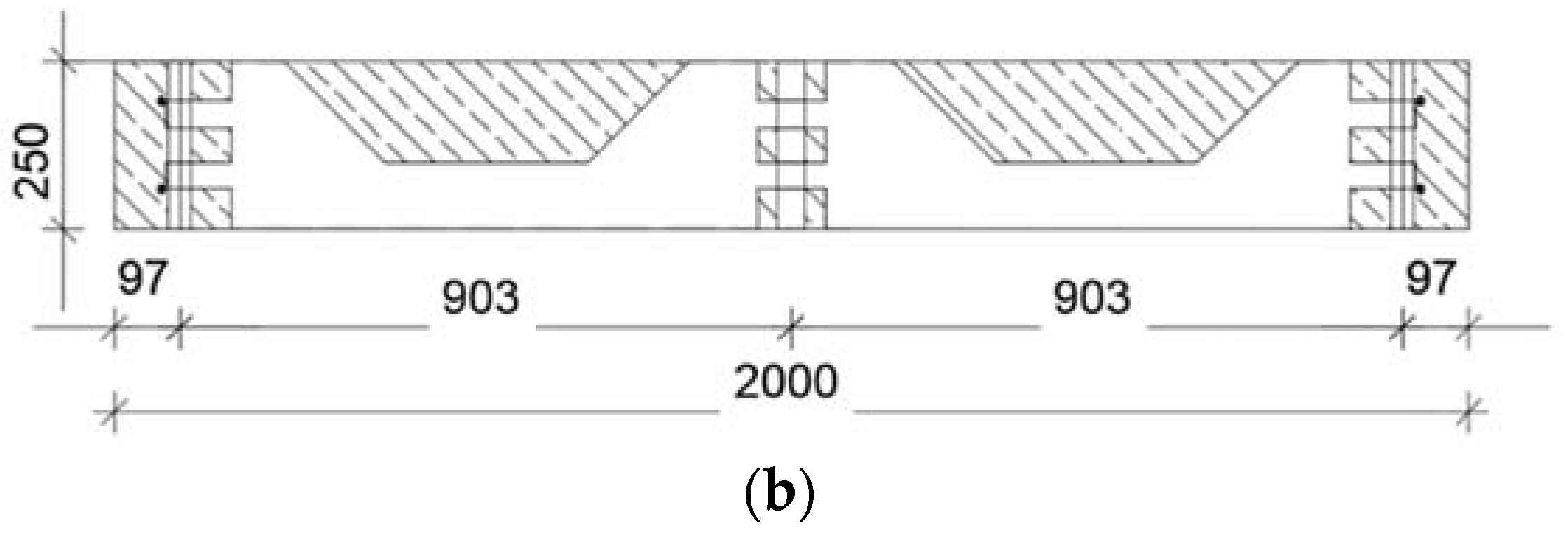
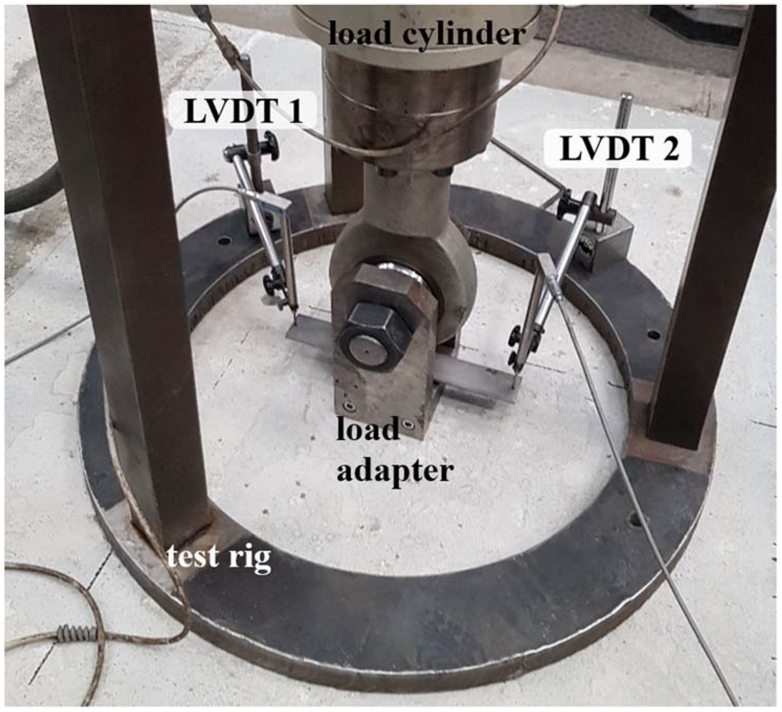
2.3. Testing Configuration and Procedure
3. Results and Discussion
3.1. Overview of Results and Variability Evaluation
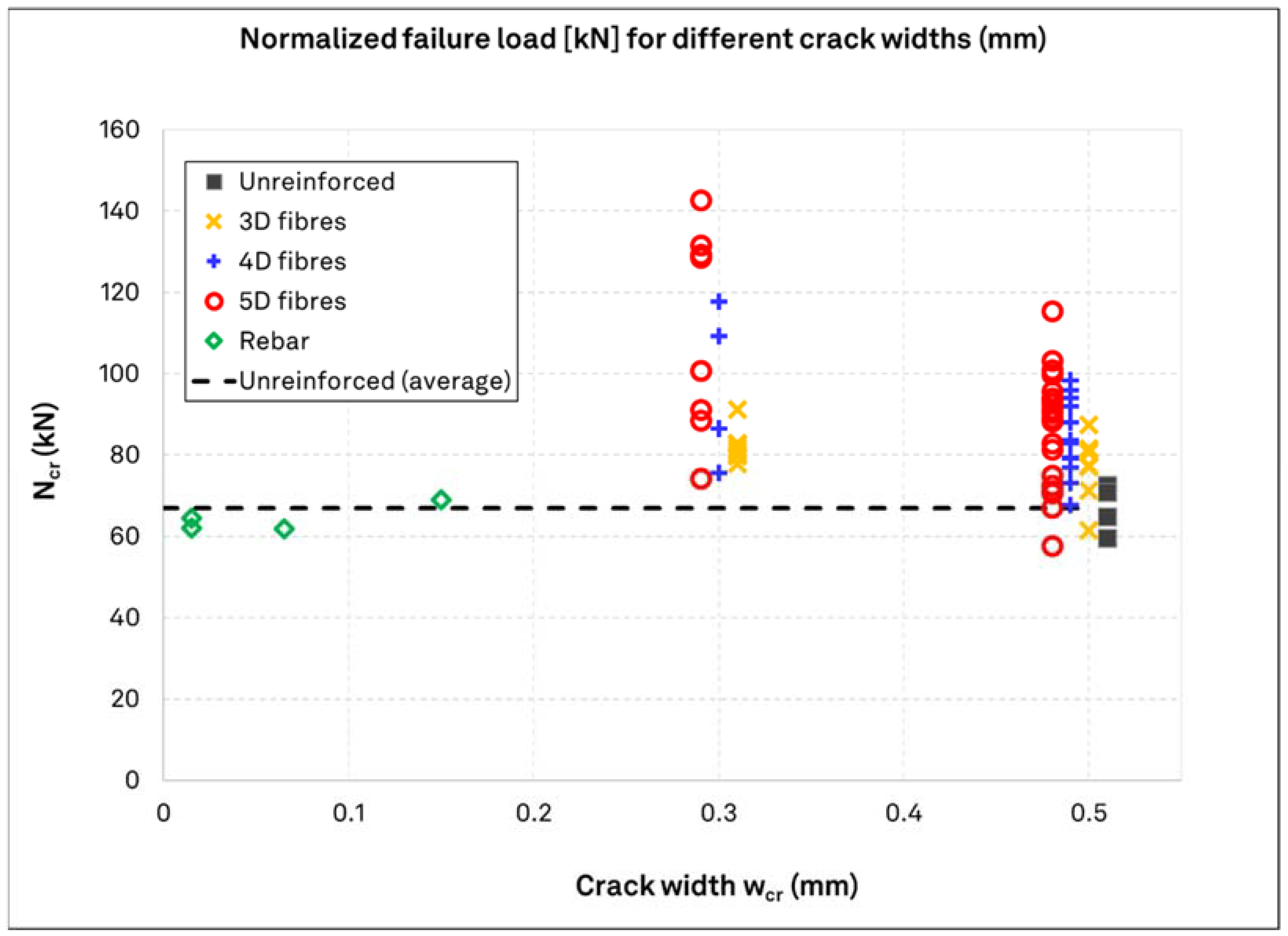
3.2. Failure Loads for Uncracked and Cracked Concrete
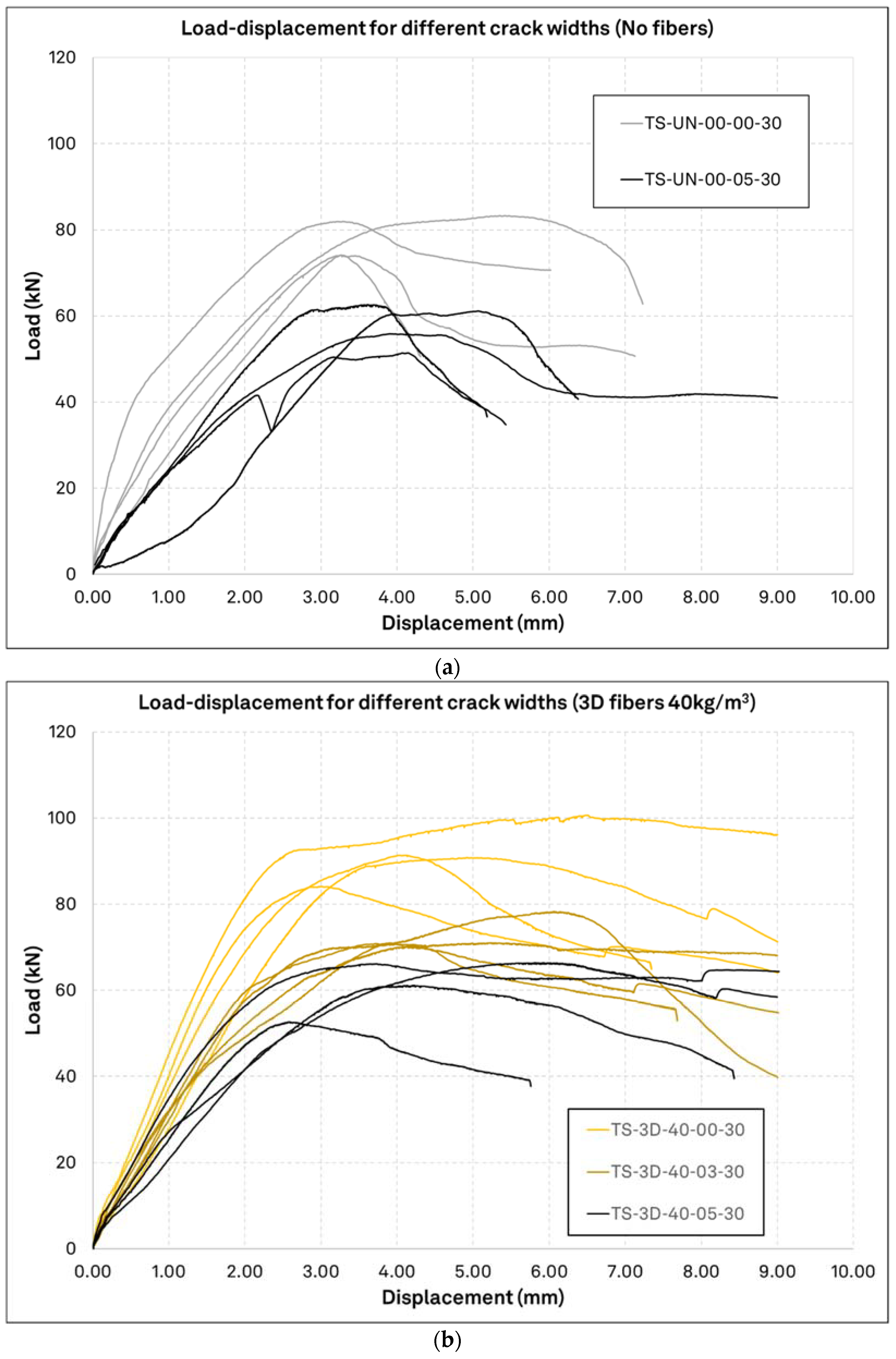
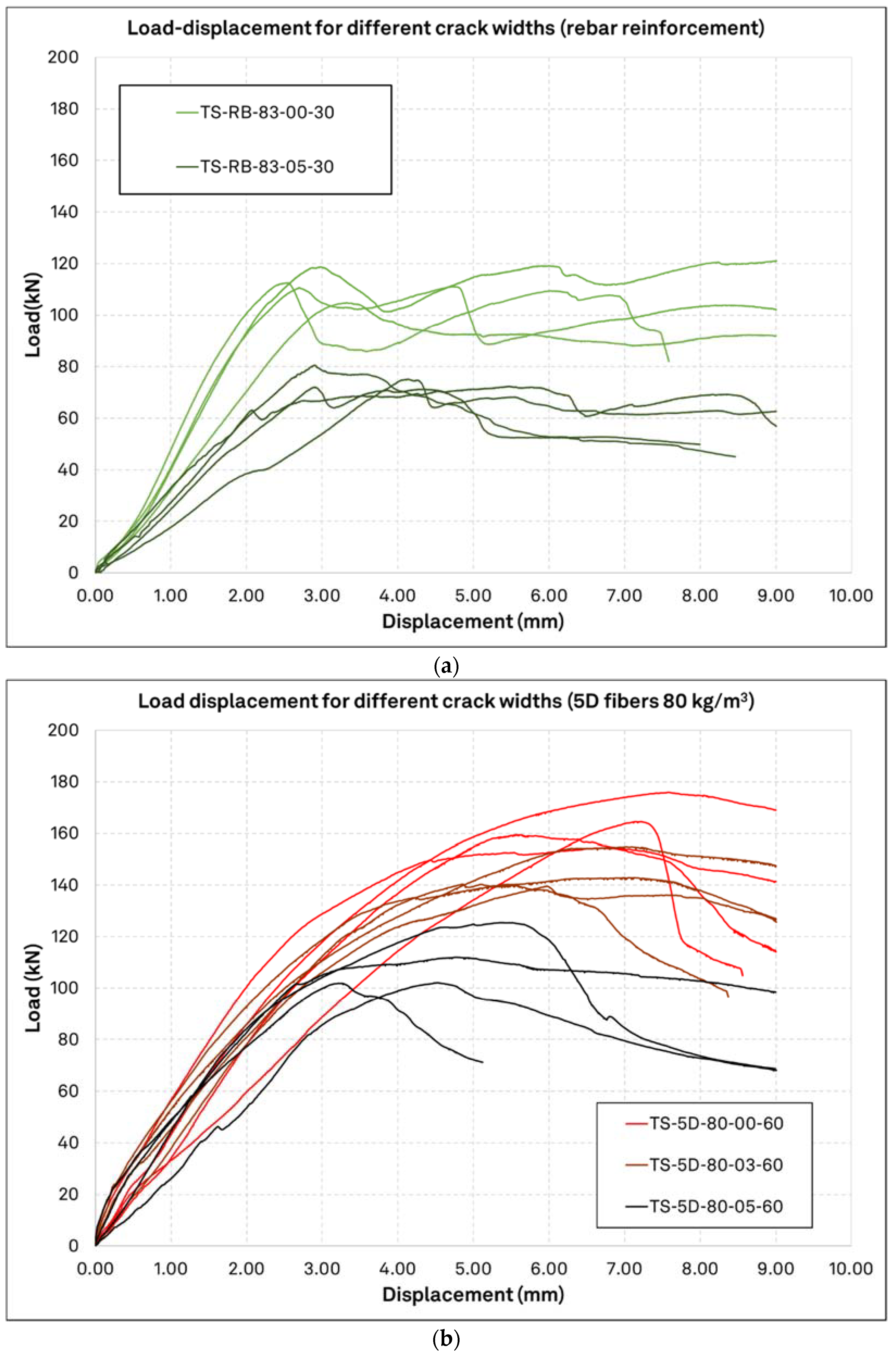
3.3. Load-Displacement Performance
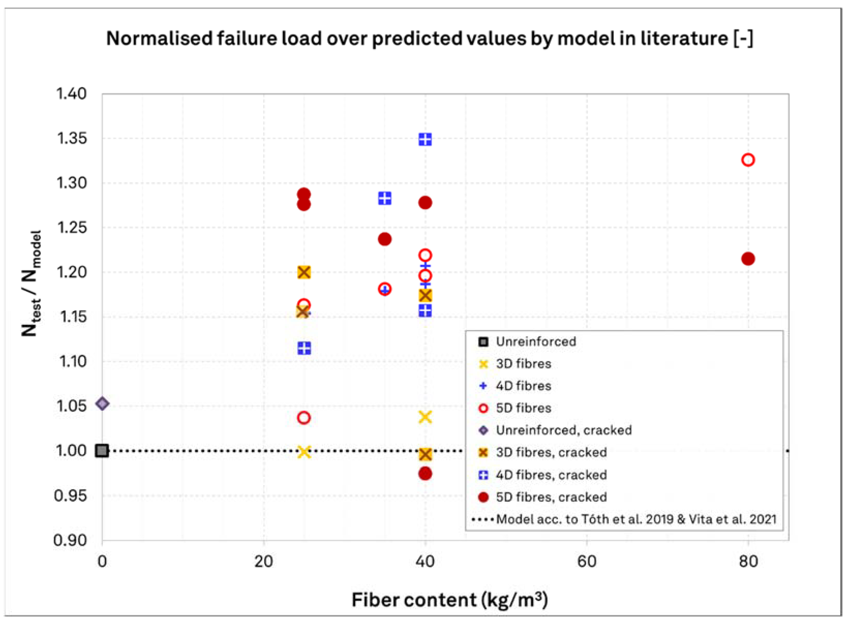
3.4. Comparison to Currently Proposed Models
4. Conclusions
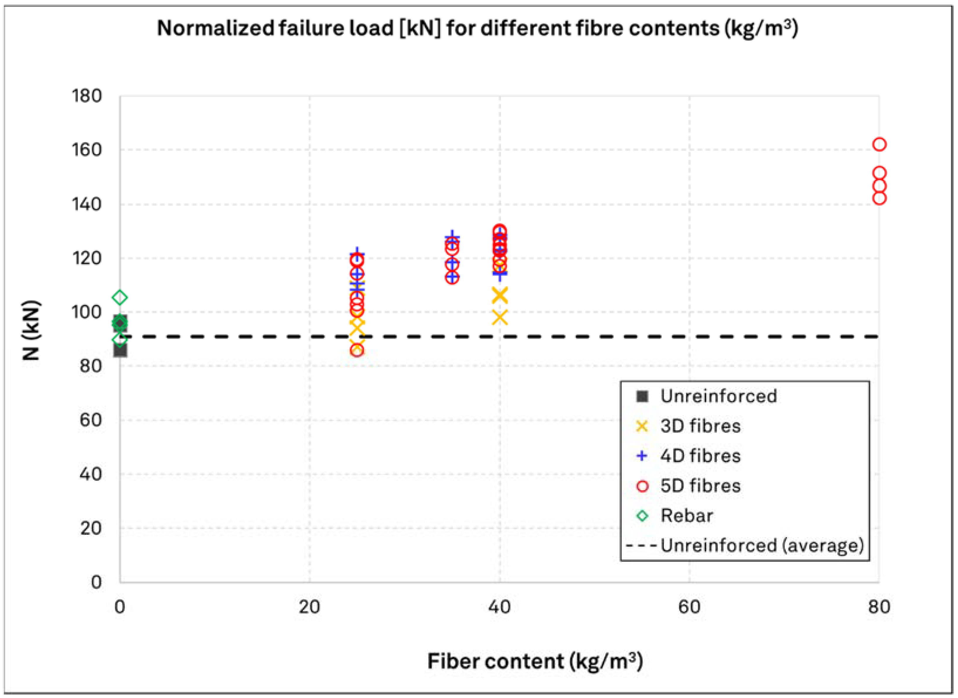
- The addition of fibers clearly leads to increase in the load-bearing resistance at mean values. This increase begins with 10% for 3D fibers at a dosage of 25 kg/m3 and goes up to approximately 70% for 5D fibers at a dosage of 80 kg/m3, with variation coefficients in a commonplace order of magnitude for concrete related failure modes of fastenings. Additionally, 4D and 5D fibers provide a similar rate of increase. While 3D fibers can still contribute to the concrete breakout capacity, it is to a lesser degree for otherwise the same fiber dosage and concrete strength. Therefore, for the configurations tested applying the same anchor design approach for SFRC as for concrete without fibers is on the safe side.
- The fiber dosage is shown to be a very influencing fiber-related characteristic for the fastening resistance, which agrees with most previous research investigations discussed in the introduction. The type of fibers used has also a very strong influence on the anchor load-bearing resistance. Comparing fibers with hooked-ends and the same length and diameter, but with different material strength and end-anchorage shape, the load increase by use of 3D fibers was in the range of 5 and 15%, while 4D and 5D fibers led to an overall resistance increase in the range of 10 and 40% for fiber dosages of 25 kg/m3 and 40 kg/m3, respectively.
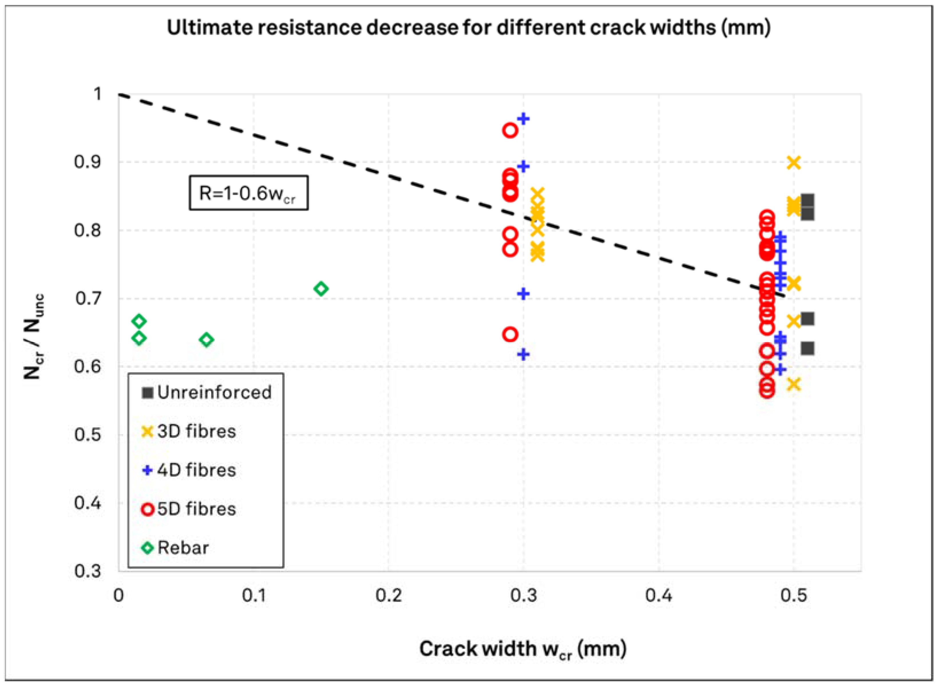
- Fiber reinforced concrete has indicated a beneficial behavior in cracked concrete. The load bearing capacity of anchors in cracked fiber reinforced concrete was higher than in unreinforced concrete. A relation of the fiber type and the anchor performance in cracked concrete is evident. The 3D fibers have the least influence, while 4D and 5D fiber have a similar effect. Considering solely the SFRC specimens tested herein, the mean load reduction of anchors in cracked SFRC in relation to the crack width can be described by an analogy to the crack width, which is in reasonable agreement with the few previous studies discussed in the introduction.
- The surface rebar reinforcement does not influence the load bearing capacity significantly. The resistance increment for a favorably arranged reinforcement presented herein is similar to that of 3D fibers with 25 kg/m3. There is no contribution of the rebar to the load capacity in cracked concrete, and there is no apparent correlation between the crack width and the load reduction. Nonetheless, in both cracked and uncracked concrete the ductility of the anchors has increased remarkably.
- Both typical surface reinforcement and fiber reinforcement in concrete influence the ductility of single anchors. There is notable increase in the ductility of the anchors behavior in the case of concrete cone failure mode for both types of reinforcement. For the same overall steel reinforcement quantity, high performance fibers provide a significantly higher load bearing capacity over that of rebar reinforcement.
- The adequacy of currently proposed design approaches in [33,35,38] is confirmed by the tests herein. In particular, the linear increase in load-bearing capacity by increasing fiber content as proposed by the equation in [33,38] is a reasonable principle. This equation can predict the results with a reasonable accuracy for 3D fibers and with conservatism for 4D and 5D fibers. The test results confirm that the equation is applicable for a ratio of fiber length to embedment of 1.7. Furthermore, the high scatters in test results for concrete with fiber reinforcement at 25 kg/m3 advocates for an applicability limit at or close to this lower bound fiber dosage. The reduction multiplier of 0.7 for the prediction of the load capacity in concrete anchors located in a 0.3 mm crack, as proposed by [35], is in agreement with the investigation results.
Author Contributions
Funding
Institutional Review Board Statement
Informed Consent Statement
Data Availability Statement
Acknowledgments
Conflicts of Interest
References
- Spyridis, P.; Nasekhian, A.; Skalla, G. Design of SCL structures in London/Entwurf von Tunnelbauwerken in Spritzbeton-Bauweise am Beispiel London. Geomech. Tunn. 2013, 6, 66–80. [Google Scholar] [CrossRef]
- Psomas, S.; Coppenhall, P.; Rimes, M.; Brown, D.; Cheevers, E. Design and construction of permanent steel fibre reinforced sprayed concrete lining shafts for Thames Tideway West Project UK. In Tunnels and Underground Cities: Engineering and Innovation meet Archaeology, Architecture and Art; CRC Press: Boca Raton, FL, USA, 2019; pp. 2909–2919. [Google Scholar]
- Caratelli, A.; Meda, A.; Rinaldi, Z. Design according to MC2010 of a fibre-reinforced concrete tunnel in Monte Lirio, Panama. Struct. Concr. 2012, 13, 166–173. [Google Scholar] [CrossRef]
- Desmettre, C.; Charron, J.P. Use of Steel-Fibre Reinforced Concrete to Extend Service Life of Temporary Safety Concrete Barriers. In RILEM-Fib International Symposium on Fibre Reinforced Concrete 2021; Springer: Cham, Switzerland, 2021; pp. 615–627. [Google Scholar]
- Coppens, E.; Itterbeeck, P.V.; Dooms, B.; Richir, T.; Debournonville, G. A Fiber Reinforced Concrete for a Nuclear Waste Container. In RILEM-Fib International Symposium on Fibre Reinforced Concrete 2021; Springer: Cham, Switzerland, 2021; pp. 628–639. [Google Scholar]
- di Prisco, M.S.F.; Failla, C.; Finazzi, P.; Siboni, A.; Bassani, A.; Nava, G.; Colombo, M. Innovative SFRC applications: An industrial building in Como. In Proceedings of the Italian Concrete Days, Lecco, Italy, 14–15 June 2018; pp. 1–10. [Google Scholar]
- Serna, P.; Arango, S.; Ribeiro, T.; Núñez, A.M.; Garcia-Taengua, E. Structural cast-in-place SFRC: Technology, control criteria and recent applications in Spain. Mater. Struct. 2009, 42, 1233–1246. [Google Scholar] [CrossRef]
- Empelmann, M.; Teutsch, M.; Wichers, M. Baukonstruktionen aus Faserbeton. (Building structures made of fibre-reinforced concrete). In Beton-Kalender 2011: Schwerpunkte: Kraftwerke, Faserbeton; Ernst & Sohn: Berlin, Germany, 2010; pp. 89–139. [Google Scholar]
- Steinle, A.; Bachmann, H.; Tillmann, M. Bauen mit Betonfertigteilen im Hochbau; Precast Concrete Construction in Buildings; John Wiley & Sons: Hoboken, NJ, USA, 2018. [Google Scholar]
- Massicotte, B.; Faggio, L.; Cordoni, N.; Nour, A.; Conciatori, D. Design and construction of SFRC bridge decks–building on past experience and recent developments. In Proceedings of the FRC 2014 Joint ACI, Montreal, QC, Canada, 24–25 July 2014; pp. 134–153. [Google Scholar]
- Ng, T.S.; Htut, T. Structural application of steel fibres reinforced concrete with and without conventional reinforcement. In Australian Structural Engineering Conference: ASEC 2018; Engineers Australia: Barton, Australia, 2018; pp. 624–634. [Google Scholar]
- Curbach, M.; Bergmeister, K.; Mark, P. Baukulturingenieure−Civil Engineering Goes Green. In Nachhaltigkeit, Ressourceneffizienz und Klimaschutz: Konstruktive Lösungen für das Planen und Bauen-Aktueller Stand der Technik; John Wiley & Sons: Hoboken, NJ, USA, 2021; p. 39. [Google Scholar]
- DAfStB—German Committee for Reinforced Concrete. Nachhaltig Bauen mit Beton—Planungshilfe des Deutschen Ausschusses für Stahlbeton DAfStb (Sustainable Construction with Concrete—Planning aid of the German Committee for Reinforced Concrete); Deutscher Ausschuss für Stahlbeton e.V. (DAfStb): Berlin, Germany, 2021. [Google Scholar]
- Monteiro, P.J.; Miller, S.A.; Horvath, A. Towards sustainable concrete. Nat. Mater. 2017, 16, 698–699. [Google Scholar] [CrossRef] [PubMed]
- Holschemacher, K.; Dehn, F.; Müller, T.; Lobisch, F. Grundlagen des Faserbetons/Fundamentals of fibre concrete. In Beton Kalender 2017: Spannbeton Spezialbetone; Wiley: Hoboken, NJ, USA, 2016; Volume 106, pp. 381–472. [Google Scholar] [CrossRef]
- Breitenbücher, R.; Meschke, G.; Song, F.; Zhan, Y. Experimental, analytical and numerical analysis of the pullout behaviour of steel fibers considering different fiber types, inclinations and concrete strengths. Struct. Concr. 2014, 15, 126–135. [Google Scholar] [CrossRef]
- Look, K.; Oettel, V.; Heek, P.; Empelmann, M.; Mark, P. Bemessen mit Stahlfaserbeton. In Beton Kalender 2021: Fertigteile Integrale Bauwerke; Wiley: Hoboken, NJ, USA, 2021; Volume 2021, pp. 797–874. [Google Scholar]
- Eligehausen, R.; Mallée, R.; Silva, J.F. Anchorage in Concrete Construction; John Wiley & Sons: Hoboken, NJ, USA, 2006. [Google Scholar]
- EN 1992-4:2018; Design of concrete structures. Design of Fastenings for Use in Concrete (Eurocode 2—Part 4). CEN—European Committee for Standardization: Brussels, Belgium, 2018.
- Eligehausen, R.; Balogh, T. Behavior of fasteners loaded in tension in cracked reinforced concrete. Struct. J. 1995, 92, 365–379. [Google Scholar]
- Holschemacher, K.; Klug, Y.; Wittmann, F. Experimental Investigations on Fastenings in Steel Fiber Reinforced Concrete. Univ. Leipz. Inst. Für Massivbau Und Baust.-IMB Hrgs. LACER-Leipz. Annu. Civ. Eng. Rep. 2002, 7, 145–158. [Google Scholar]
- Gesoglu, M.; Ozturan, T.; Ozel, M.; Guneyisi, E. Tensile behavior of post-installed anchors in plain and steel fiber-reinforced normal-and high-strength concretes. ACI Struct. J. 2005, 102, 224. [Google Scholar]
- Kurz, C.; Thiele, C.; Schnell, J.; Reuter, M.; Vitt, G. Tragverhalten von Dübeln in Stahlfaserbeton. Bautechnik 2012, 89, 545–552. [Google Scholar] [CrossRef]
- Coventry, K.; Richardson, A.; McIntyre, C.; Aresh, B. Pullout performance of chemical anchor bolts in fiber concrete. In Proceedings of the 6th Conference on Fiber Concrete, Prague, Czech Republic, 8–9 September 2011. [Google Scholar]
- Grosser, P.R. Load-Bearing Behavior and Design of Anchorages Subjected to Shear and Torsion Loading in Uncracked Concrete. Ph.D. Thesis, University of Stuttgart, Stuttgart, Germany, 2012. [Google Scholar]
- Cattaneo, S.; Muciaccia, G.; Rosati, G. Expansion anchors in high performance concrete. Connections between Steel and Concrete. In Proceedings of the 2nd International Symposium, Stuttgart, Germany, 4–7 September 2007; p. 297. [Google Scholar]
- Cattaneo, S.; Muciaccia, G. Adhesive anchors in high performance concrete. Mater. Struct. 2016, 49, 2689–2700. [Google Scholar] [CrossRef]
- Nilforoush, R.; Nilsson, M.; Elfgren, L. Experimental evaluation of tensile behaviour of single cast-in-place anchor bolts in plain and steel fibre-reinforced normal-and high-strength concrete. Eng. Struct. 2017, 147, 195–206. [Google Scholar] [CrossRef]
- Dengg, F.; Zeman, O.; Voit, K.; Bergmeister, K. Fastening application in concrete using recycled tunnel excavation material. Struct. Concr. 2018, 19, 374–386. [Google Scholar] [CrossRef]
- Hlavicka, V.; Lublóy, É.E. Experimental study on the behaviour of bonded anchoring systems in fibre reinforcement concrete. Concr. Struct. 2018, 19, 28–33. [Google Scholar] [CrossRef]
- Delhomme, F.; Brun, M. Pullout Tests on Post-installed Bonded Anchors in Ultra-high Performance Fiber Reinforced Concrete. Struct. Eng. Int. 2019, 29, 417–424. [Google Scholar] [CrossRef]
- Schwenn, M.; Voit, K.; Zeman, O.; Bergmeister, K. Post-installed mechanical fasteners in high strength and ultra-high strength performance concrete. Civ. Eng. Des. 2019, 1, 161–167. [Google Scholar] [CrossRef]
- Tóth, M.; Bokor, B.; Sharma, A. Anchorage in steel fiber reinforced concrete–concept, experimental evidence and design recommendations for concrete cone and concrete edge breakout failure modes. Eng. Struct. 2019, 181, 60–75. [Google Scholar] [CrossRef]
- Ayoubi, M.; Mahrenholtz, C.; Nell, W. Influence of the Steel Fibers on the Tension and Shear Resistance of Anchoring with Anchor Channels and Channel Bolts Cast in Concrete. In Fiber Reinforced Concrete: Improvements and Innovations; Serna, P., Llano-Torre, A., Martí-Vargas, J.R., Navarro-Gregori, J., Eds.; BEFIB 2020; RILEM Bookseries; Springer: Cham, Switzerland, 2021; Volume 30. [Google Scholar] [CrossRef]
- Vita, N.; Sharma, A. Behaviour of single bonded anchors in non-cracked and cracked steel fiber reinforced concrete under short-time tensile loading. Eng. Struct. 2021, 245, 112900. [Google Scholar] [CrossRef]
- Kocur, G.K.; Ricker, M.; Zecherle, K.; Häusler, F. Experimental investigations on the concrete breakout capacity of crimped sleeves in steel fiber-reinforced concrete. Eng. Struct. 2021, 244, 112758. [Google Scholar] [CrossRef]
- Spyridis, P.; Hufelschulte, F.; Mellios, N. Einfluss der Stahlfaserbewehrungsarten auf den Betonversagenswiderstand von Befestigungen/Influence of the steel fibre reinforcement type on the concrete breakout resistance of fastenings. In Beton- und Stahlbetonbaul; Wiley: Hoboken, NJ, USA, 2022; Volume 117. [Google Scholar] [CrossRef]
- Tóth, M.; Bokor, B.; Sharma, A. Befestigungen im stahlfaserverstärkten Beton bei Betonbruch—Stand der Technik und Bemessungsansatz/Anchorages in Steel Fiber Reinforced Concrete in the case of concrete breakout failure—State of the art and design concept. Bauingenieur 2021, 96, 254–265. [Google Scholar] [CrossRef]
- EAD 330232-01-0601; Mechanical Fasteners for use in Concrete; Decision (EU) 2021/1789. EOTA—European Organisation for Technical Approvals: Brussels, Belgium, 2021.
- Abdallah, S.; Fan, M.; Rees, D.W. Predicting pull-out behaviour of 4D/5D hooked end fibers embedded in normal-high strength concrete. Eng. Struct. 2018, 172, 967–980. [Google Scholar] [CrossRef]
- Abdallah, S.; Rees, D.W.; Ghaffar, S.H.; Fan, M. Understanding the effects of hooked-end steel fiber geometry on the uniaxial tensile behaviour of self-compacting concrete. Constr. Build. Mater. 2018, 178, 484–494. [Google Scholar] [CrossRef] [Green Version]
- EN 14399-4:2015; High-Strength Structural Bolting Assemblies for Preloading—Part 4: System HV—Hexagon Bolt and Nut Assemblies. CEN—European Committee for Standardization: Brussels, Belgium, 2015.
- EN 14399-6:2015; High-Strength Structural Bolting Assemblies for Preloading—Part 6: Plain Chamfered Washers. CEN—European Committee for Standardization: Brussels, Belgium, 2015.
- JCSS—Joint Committee on Structural Safety. Probabilistic Model Code, Part 3: Resistance Models. 2002. Available online: https://www.jcss-lc.org/jcss-probabilistic-model-code/ (accessed on 8 December 2021).
- Yazıcı, Ş.; Sezer, G.İ. The effect of cylindrical specimen size on the compressive strength of concrete. Build. Environ. 2007, 42, 2417–2420. [Google Scholar] [CrossRef]


| Test Series | Reinforcement Type | Fiber Dosage (kg/m3) | Crack Width (mm) | Target Concrete Strength (MPa) |
|---|---|---|---|---|
| TS-UN-00-00-30 | - | - | - | 30 |
| TS-UN-00-05-30 | - | - | 0.5 | 30 |
| TS-3D-25-00-30 | 3D | 25 | - | 30 |
| TS-3D-25-03-30 | 3D | 25 | 0.3 | 30 |
| TS-3D-25-05-30 | 3D | 25 | 0.5 | 30 |
| TS-3D-40-00-30 | 3D | 40 | - | 30 |
| TS-3D-40-03-30 | 3D | 40 | 0.3 | 30 |
| TS-3D-40-05-30 | 3D | 40 | 0.5 | 30 |
| TS-4D-25-00-30 | 4D | 25 | - | 30 |
| TS-4D-25-05-30 | 4D | 25 | 0.5 | 30 |
| TS-4D-40-00-30 | 4D | 40 | - | 30 |
| TS-4D-40-05-30 | 4D | 40 | 0.5 | 30 |
| TS-4D-40-00-60 | 4D | 40 | - | 60 |
| TS-4D-40-03-60 | 4D | 40 | 0.3 | 60 |
| TS-4D-40-05-60 | 4D | 40 | 0.5 | 60 |
| TS-4D-35-00-40 | 4D | 35 | - | 40 |
| TS-5D-25-00-60 | 5D | 25 | - | 60 |
| TS-5D-25-05-60 | 5D | 25 | 0.5 | 60 |
| TS-5D-25-00-30 | 5D | 25 | - | 30 |
| TS-5D-25-03-30 | 5D | 25 | 0.3 | 30 |
| TS-5D-25-05-30 | 5D | 25 | 0.5 | 30 |
| TS-5D-35-00-40 | 5D | 35 | - | 40 |
| TS-5D-40-00-40 | 5D | 40 | - | 40 |
| TS-5D-40-05-40 | 5D | 40 | 0.5 | 40 |
| TS-5D-40-00-60 | 5D | 40 | - | 60 |
| TS-5D-40-05-60 | 5D | 40 | 0.5 | 60 |
| TS-5D-80-00-60 | 5D | 80 | - | 60 |
| TS-5D-80-03-60 | 5D | 80 | 0.3 | 60 |
| TS-5D-80-05-60 | 5D | 80 | 0.5 | 60 |
| TS-RB-83-00-60 | RB | 83 | - | 30 |
| TS-RB-83-05-60 | RB | 83 | 0.5 | 30 |
| Product Type | Diameter [mm] | Length [mm] | Nominal Tensile Strength [MPa] |
|---|---|---|---|
| Dramix 3D | 0.90 | 60 | 1160 |
| Dramix 4D | 0.90 | 60 | 1500 |
| Dramix 5D | 0.90 | 60 | 2300 |
| Test Set ID | Mean Failure Load [kN] | Mean Failure Load Normalised to 45 Mpa [MPa] | Coeff. of Variation of Failure Load [—] | Mean Cube Compressive Strength [MPa] | Mean Cylinder Compressive Strength [MPa] |
|---|---|---|---|---|---|
| TS-3D-25-00-30 | 77.05 | 98.39 | 0.094 | 28.33 | 29.850 |
| TS-3D-25-03-30 | 63.23 | 79.68 | 0.014 | ||
| TS-3D-25-05-30 | 65.64 | 82.72 | 0.038 | ||
| TS-3D-40-00-30 | 91.74 | 106.96 | 0.074 | 33.1 | 33.270 |
| TS-3D-40-03-30 | 72.56 | 84.61 | 0.053 | ||
| TS-3D-40-05-30 | 61.60 | 71.82 | 0.104 | ||
| TS-4D-25-00-30 | 87.54 | 113.62 | 0.051 | 26.71 | 35.03 |
| TS-4D-25-05-30 | 59.22 | 76.87 | 0.101 | ||
| TS-4D-40-00-30 | 93.06 | 124.36 | 0.056 | 25.2 | 31.95 |
| TS-4D-40-05-30 | 62.44 | 83.44 | 0.119 | ||
| TS-4D-40-00-60 | 141.45 | 122.27 | 0.047 | 60.22 | 58.10 |
| TS-4D-40-03-60 | 112.51 | 97.25 | 0.202 | ||
| TS-4D-40-05-60 | 107.00 | 92.49 | 0.037 | ||
| TS-4D-35-00-40 | 99.81 | 121.43 | 0.056 | 30.4 | 30.4 |
| TS-5D-25-00-30 | 94.25 | 114.55 | 0.059 | 30.46 | 35.1 |
| TS-5D-25-03-30 | 72.97 | 88.69 | 0.124 | ||
| TS-5D-25-05-30 | 72.33 | 87.91 | 0.054 | ||
| TS-5D-25-00-60 | 118.75 | 102.10 | 0.133 | 60.87 | 52.26 |
| TS-5D-25-05-60 | 78.12 | 67.17 | 0.109 | ||
| TS-5D-35-00-40 | 107.01 | 119.83 | 0.047 | 35.883 | 32.25 |
| TS-5D-40-00-40 | 107.18 | 123.21 | 0.026 | 34.05 | 35.24 |
| TS-5D-40-05-40 | 76.21 | 87.61 | 0.155 | ||
| TS-5D-40-00-60 | 147.19 | 125.53 | 0.048 | 61.87 | 55.73 |
| TS-5D-40-05-60 | 104.55 | 89.16 | 0.116 | ||
| TS-5D-80-00-60 | 163.58 | 150.65 | 0.056 | 53.06 | 56.25 |
| TS-5D-80-03-60 | 144.47 | 133.04 | 0.049 | ||
| TS-5D-80-05-60 | 110.36 | 101.64 | 0.101 | ||
| TS-RB-83-00-60 | 112.86 | 96.72 | 0.067 | 61.27 | 55.68 |
| TS-RB-83-05-60 | 76.31 | 65.39 | 0.078 | ||
| TS-Un-00-00-30 | 78.39 | 90.88 | 0.063 | 33.48 | 37.86 |
| TS-Un-00-05-30 | 57.77 | 66.97 | 0.089 |
Publisher’s Note: MDPI stays neutral with regard to jurisdictional claims in published maps and institutional affiliations. |
© 2022 by the authors. Licensee MDPI, Basel, Switzerland. This article is an open access article distributed under the terms and conditions of the Creative Commons Attribution (CC BY) license (https://creativecommons.org/licenses/by/4.0/).
Share and Cite
Spyridis, P.; Mellios, N. Tensile Performance of Headed Anchors in Steel Fiber Reinforced and Conventional Concrete in Uncracked and Cracked State. Materials 2022, 15, 1886. https://doi.org/10.3390/ma15051886
Spyridis P, Mellios N. Tensile Performance of Headed Anchors in Steel Fiber Reinforced and Conventional Concrete in Uncracked and Cracked State. Materials. 2022; 15(5):1886. https://doi.org/10.3390/ma15051886
Chicago/Turabian StyleSpyridis, Panagiotis, and Nikolaos Mellios. 2022. "Tensile Performance of Headed Anchors in Steel Fiber Reinforced and Conventional Concrete in Uncracked and Cracked State" Materials 15, no. 5: 1886. https://doi.org/10.3390/ma15051886