
Modeling of Probeless Friction Stir Spot Welding of AA2024/AISI304 Steel Lap Joint

Abstract
:1. Introduction
2. Materials and Methods
2.1. Materials
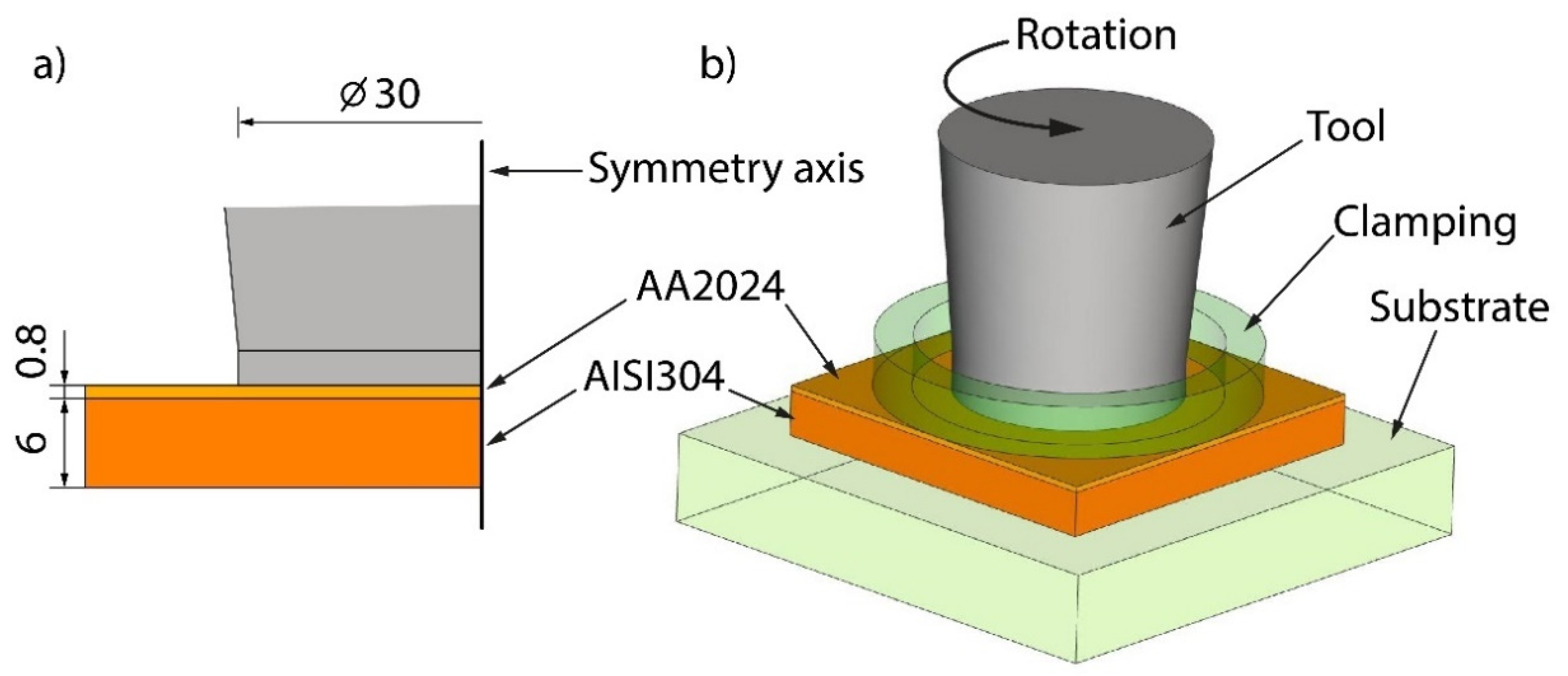
2.2. Methods
2.3. Numerical Model
- Linear increase in the RS from zero (RS0) to the rated value of RSset for separate specimens (P0 = 0).
- Tool downward movement until it touched the plate top surface (RSset; P0).
- Fast compression of the aluminum plate with an instant increase in the pressure up to the rated value of Pset. Frictional heat was generated, which was proportional to the specific frictional power.
- Formation of welding seam for the DT (RSset; Pset).
- Tool upward movement, with a pressure decreasing to P0 (RSset).
- Linear decrease in the RS from RSset to RS0 for separate specimens.
3. Results and Discussion
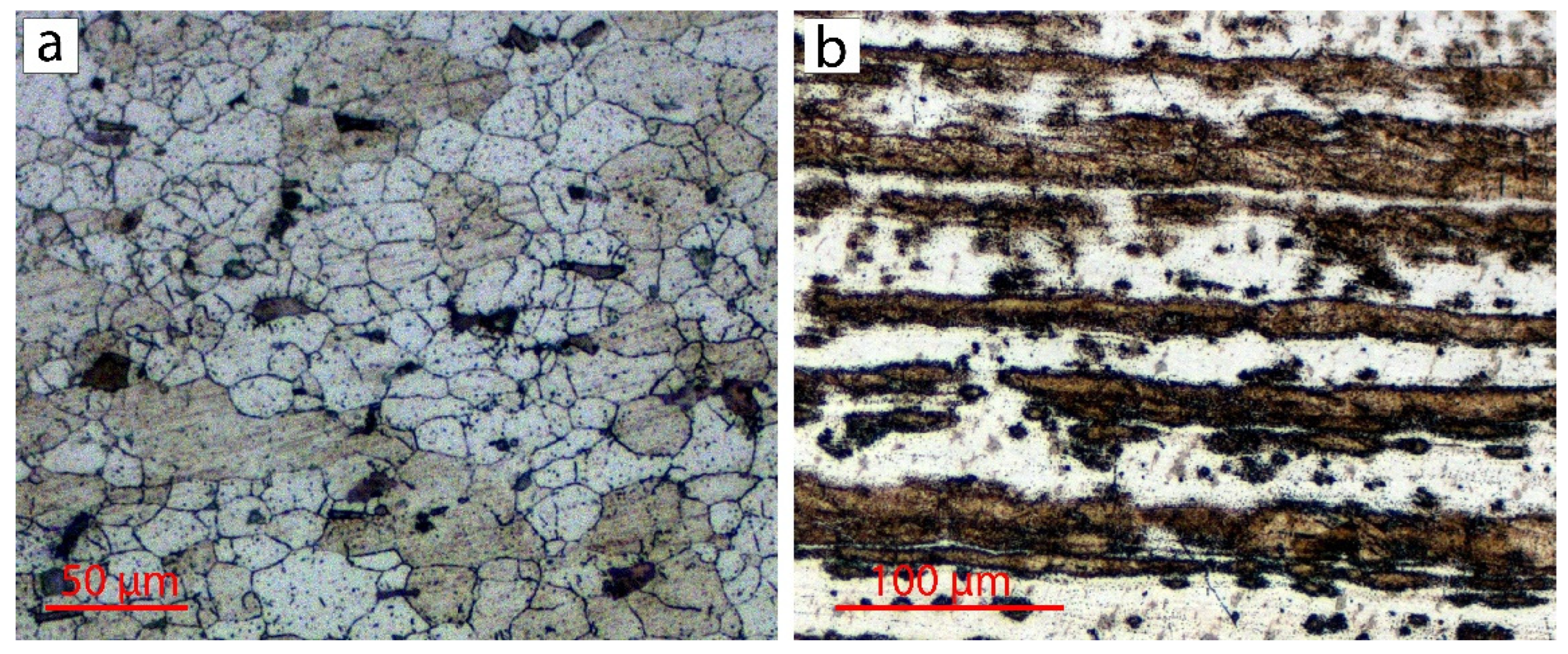
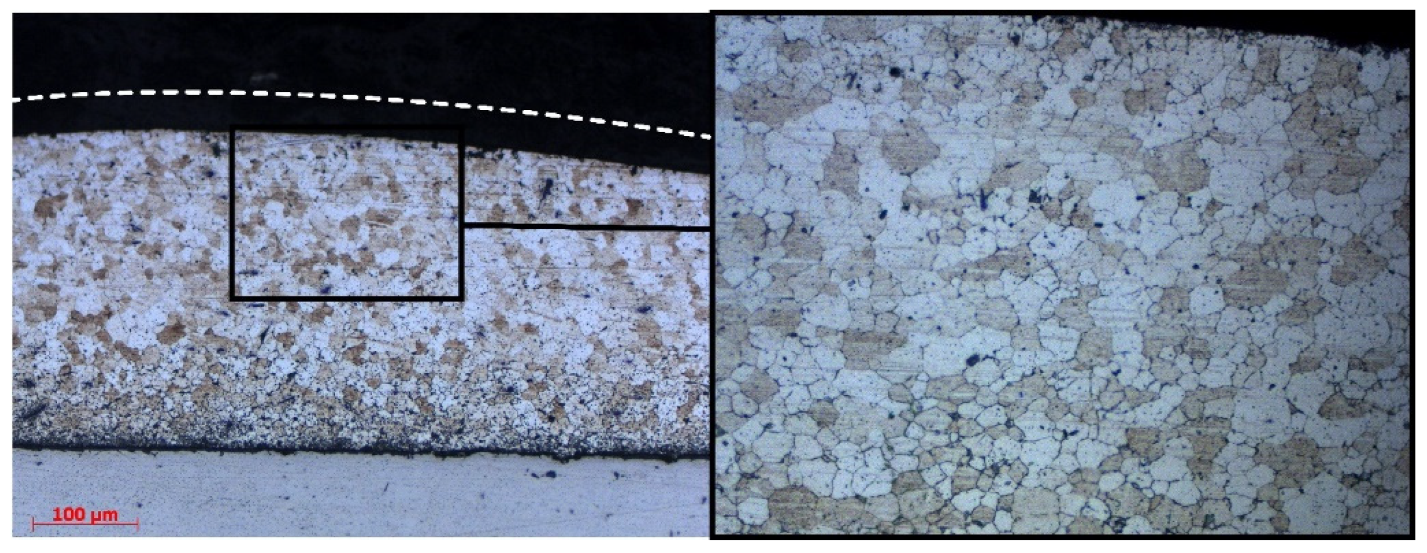
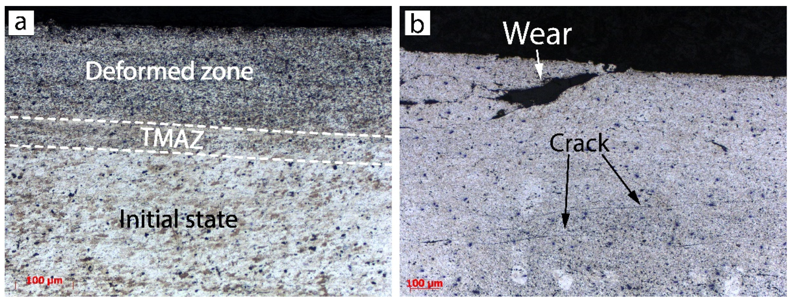
3.1. Microstructure
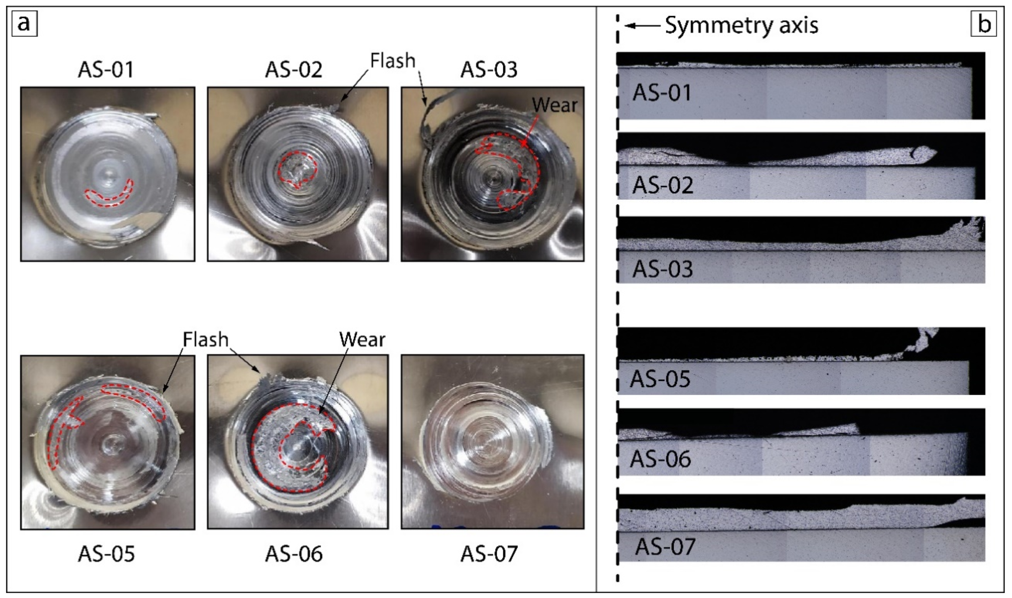
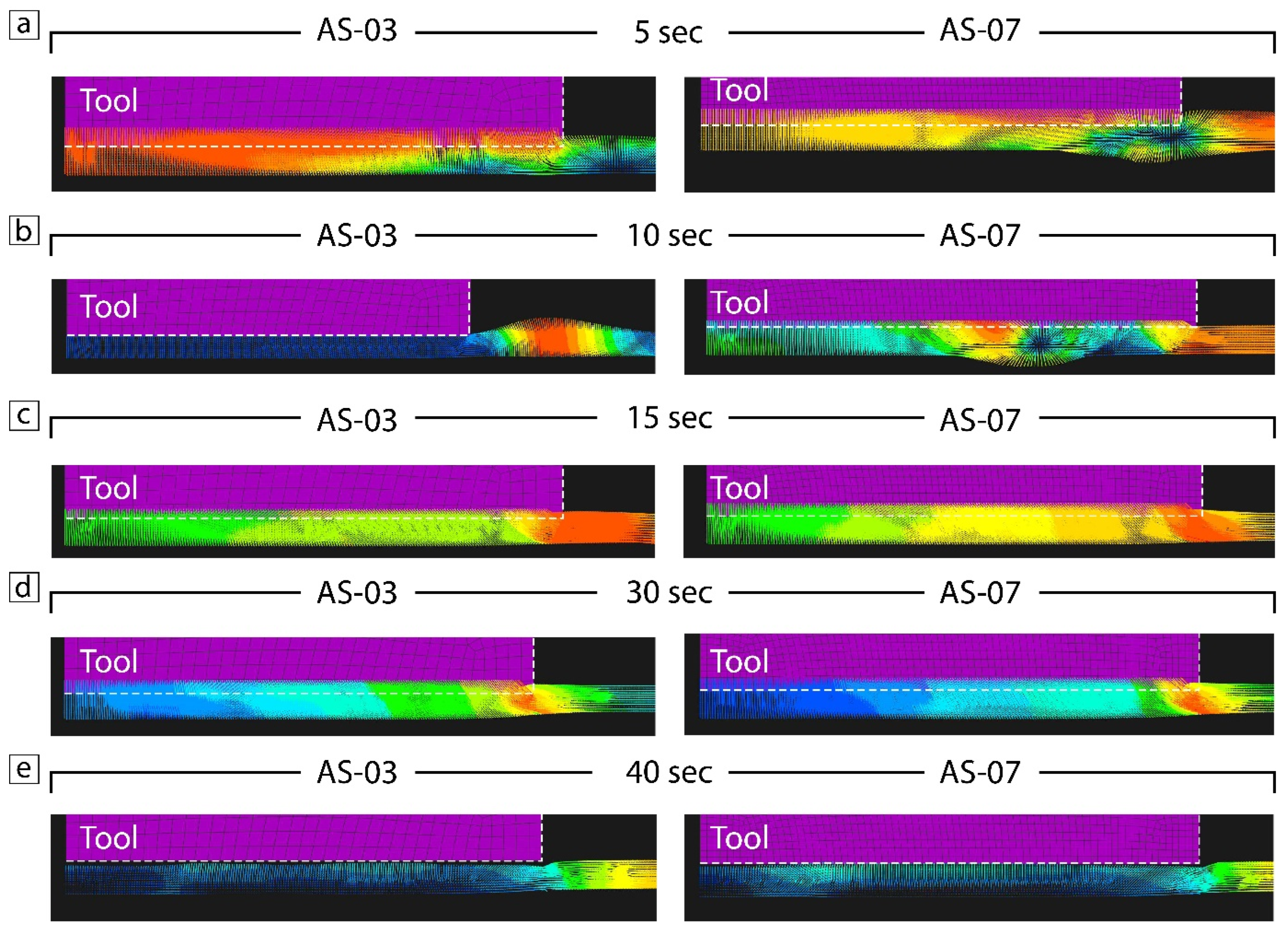
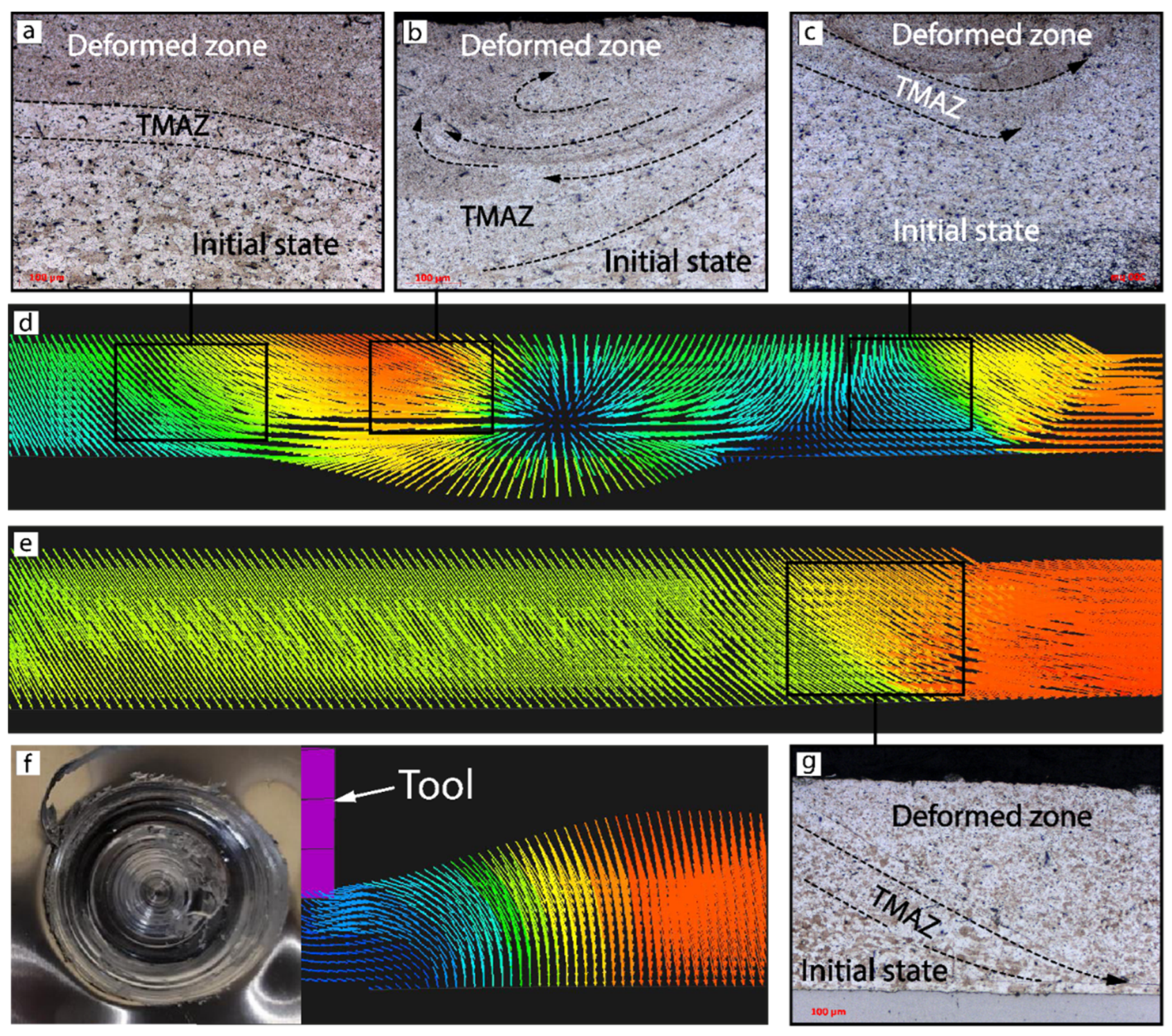
3.2. Material Flow
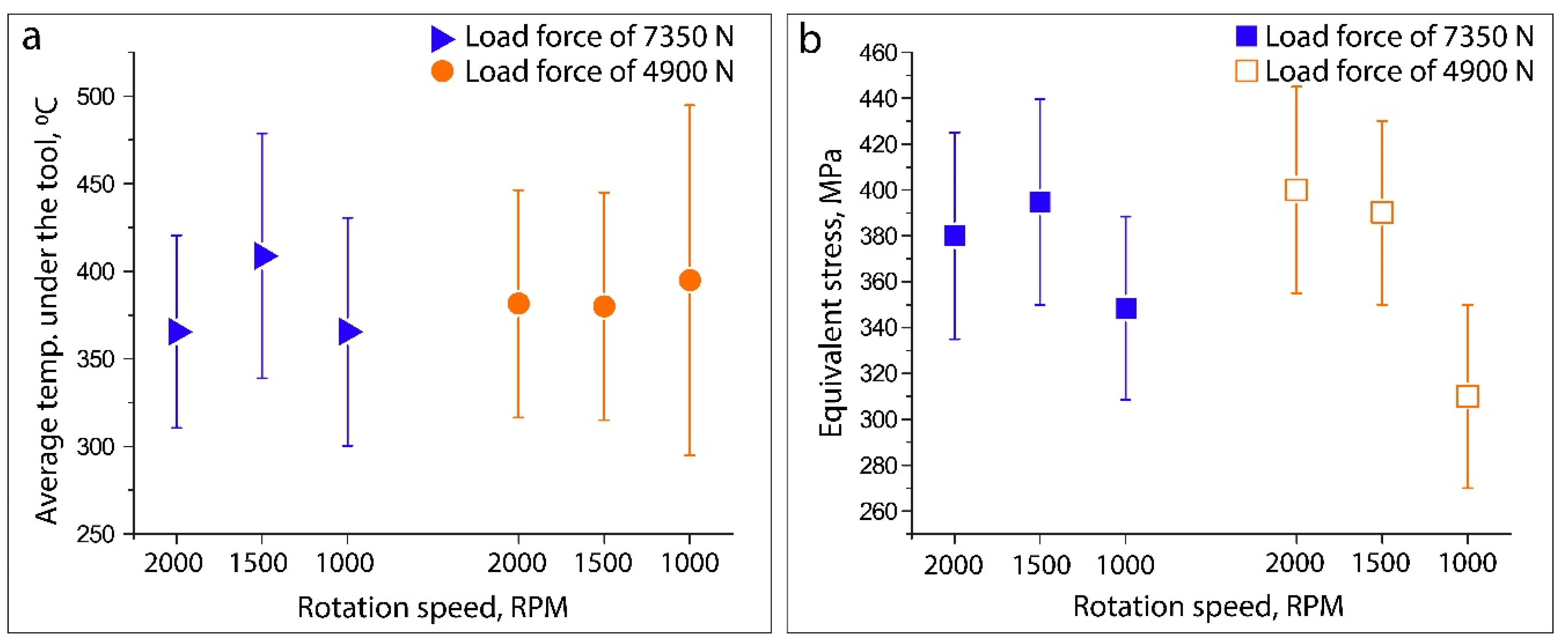
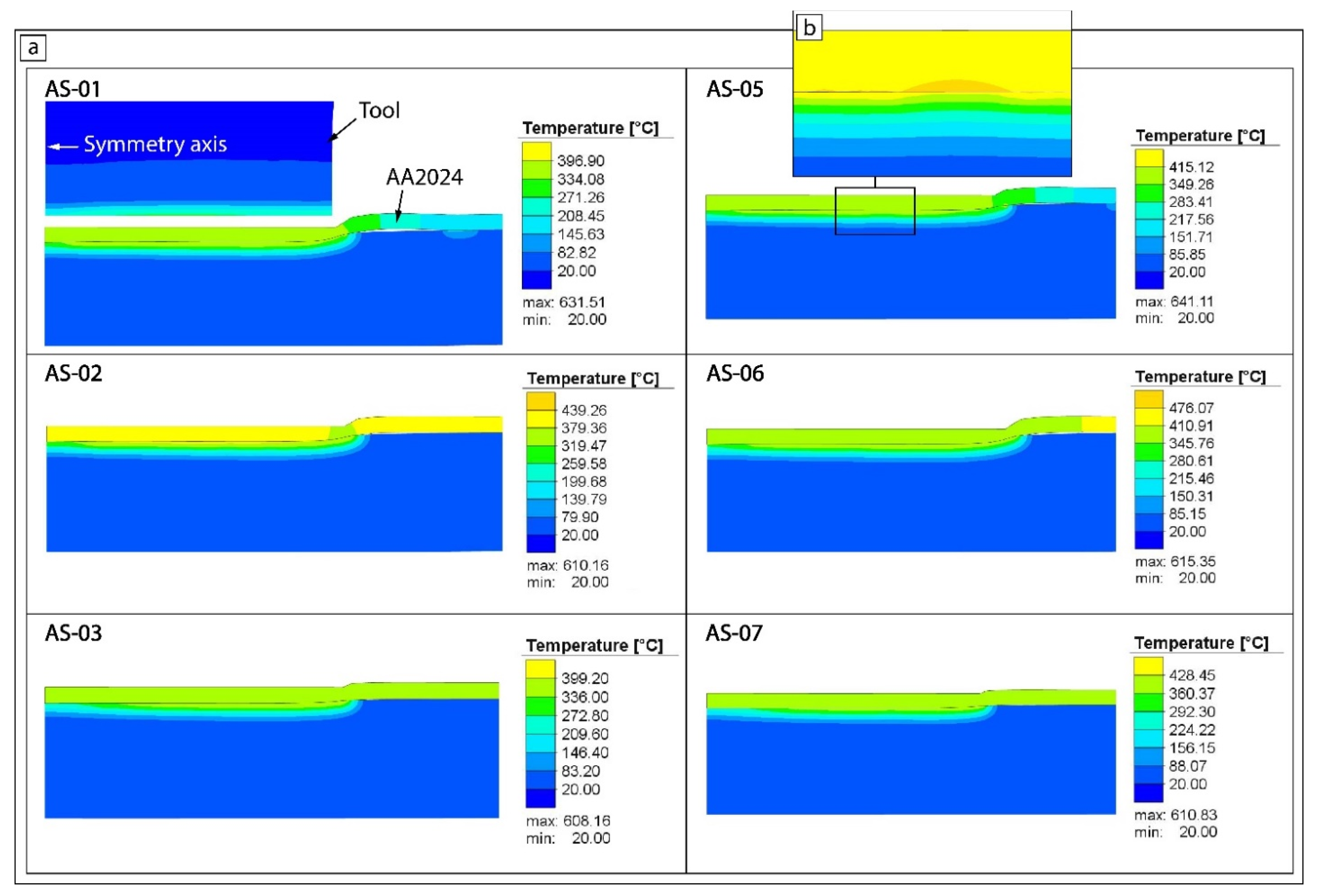
3.3. FEM Analysis: Temperature and Stress
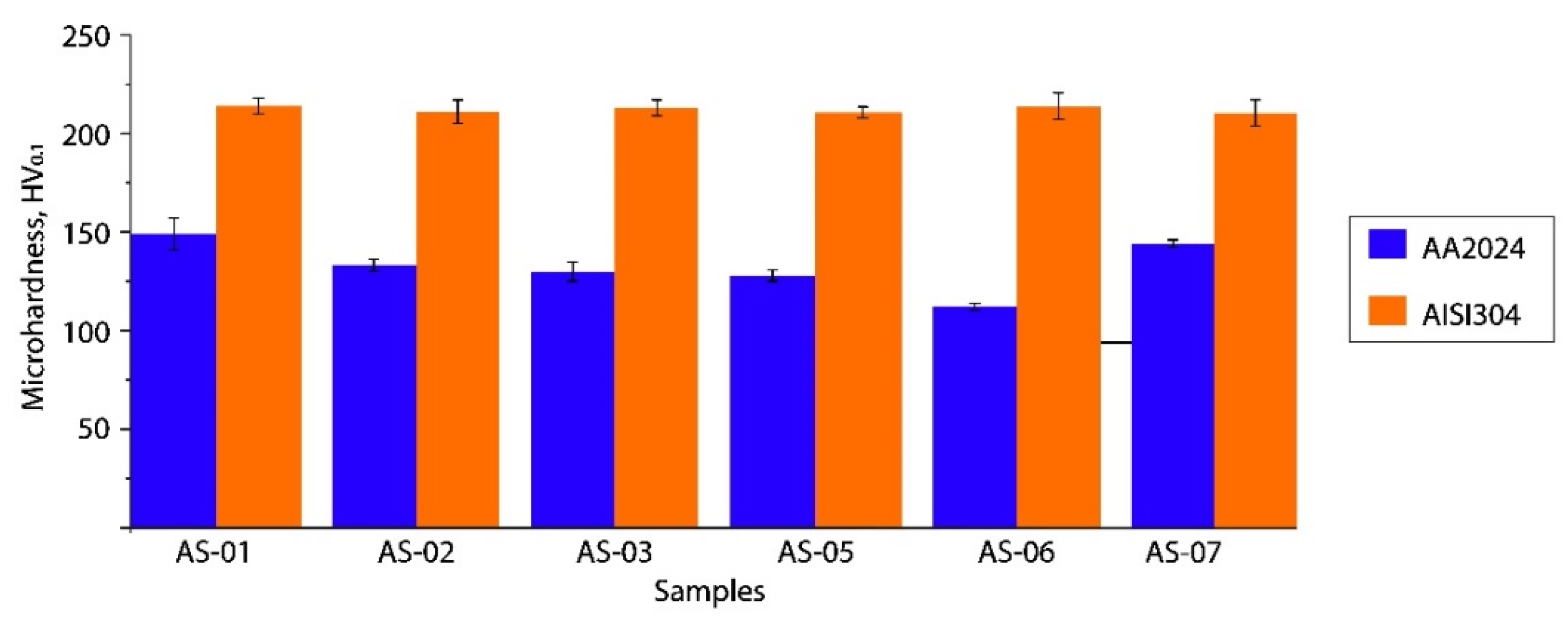
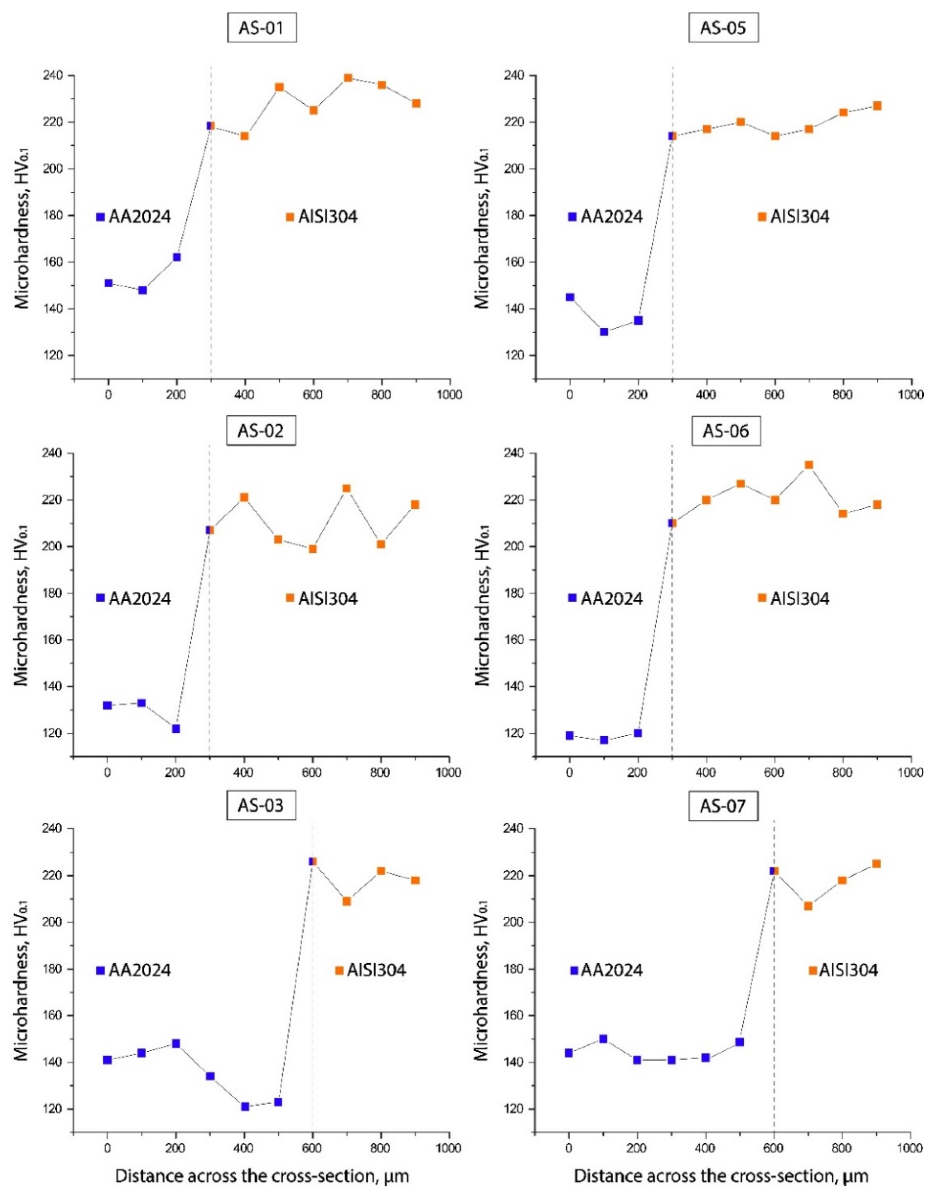
3.4. Microhardness
4. Conclusions
Author Contributions
Funding
Informed Consent Statement
Conflicts of Interest
References
- Gullino, A.; Matteis, P.; D’Aiuto, F. Review of Aluminum-To-Steel Welding Technologies. Metals 2019, 9, 315. [Google Scholar] [CrossRef] [Green Version]
- Manladan, S.M.; Yusof, F.; Ramesh, S.; Fadzil, M.; Luo, Z.; Ao, S. A review on resistance spot welding of aluminum alloys. Int. J. Adv. Manuf. Technol. 2017, 90, 605–634. [Google Scholar] [CrossRef]
- Kobayashi, S.; Yakou, T. Control of intermetallic compound layers at interface between steel and aluminum by diffu-sion-treatment. Mater. Sci. Eng. A 2002, 338, 44–53. [Google Scholar] [CrossRef]
- Casalino, G.; Angelastro, A.; Perulli, P.; Casavola, C.; Moramarco, V. Study on the fiber laser/TIG weldability of AISI 304 and AISI 410 dissimilar weld. J. Manuf. Processes 2018, 35, 216–225. [Google Scholar] [CrossRef]
- Adin, M.Ş.; Okumuş, M. Investigation of Microstructural and Mechanical Properties of Dissimilar Metal Weld Between AISI 420 and AISI 1018 Steels. Arab. J. Sci. Eng. 2022, 47, 8341–8350. [Google Scholar] [CrossRef]
- Li, M.; Yang, S.; Wang, Y.; Tao, W. Joining aluminum to steel dissimilar metals using novel resistance spot welding process. Mater. Lett. 2011, 318, 132215. [Google Scholar] [CrossRef]
- Li, M.; Tao, W.; Zhang, J.; Wang, Y.; Yang, S. Hybrid resistance-laser spot welding of aluminum to steel dissimilar materials: Microstructure and mechanical properties. Mater. Des. 2022, 221, 111022. [Google Scholar] [CrossRef]
- Atabaki, M.M.; Nikodinovski, M.; Chenier, P.; Ma, J.; Harooni, M.; Kovacevic, R. Welding of Aluminum Alloys to Steels: An Overview. J. Manuf. Sci. Prod. 2014, 14, 59–78. [Google Scholar] [CrossRef]
- Casalino, G.; Leo, P.; Mortello, M.; Perulli, P.; Varone, A. Effects of laser offset and hybrid welding on microstructure and IMC in Fe-Al dissimilar welding. Metals 2017, 7, 282. [Google Scholar] [CrossRef] [Green Version]
- Suryanarayanan, R.; Sridhar, V. Studies on the influence of process parameters in friction stir spot welded joints—A review. Mater. Today Proc. 2021, 37, 2695–2702. [Google Scholar] [CrossRef]
- Adin, M.Ş.; Işcan, B. Optimization of Welding Parameters of AISI 431 and AISI 1020 Joints Joined by Friction Welding Using Taguchi Method. Adv. Mater. Process. Technol. 2022, 9, 453–470. [Google Scholar] [CrossRef]
- Sharma, C.; Tripathi, A.; Upadhyay, V.; Verma, V.; Sharma, S.K. Friction Stir Spot Welding-Process and Weld Properties: A Review. J. Inst. Eng. Ser. D Vol. 2021, 102, 549–565. [Google Scholar] [CrossRef]
- Siddiquee, A.N.; Pandey, S. Experimental investigation on deformation and wear of WC tool during friction stir weld-ing (FSW) of stainless steel. Int. J. Adv. Manuf. Technol. 2014, 73, 479–486. [Google Scholar] [CrossRef]
- Shen, J.; Lage, S.B.M.; Suhuddin, U.F.H.; Bolfarini, C.; dos Santos, J.F. Exture development and material flow behavior during refill friction stir spot welding of AlMgSc. Metall. Mater. Trans. A 2018, 49, 241–254. [Google Scholar] [CrossRef]
- Silva, B.H.; Zepon, G.; Bolfarini, C.; dos Santos, J.F. Refill friction stir spot welding of AA6082-T6 alloy: Hook defect formation and its influence on the mechanical properties and fracture behavior. Mater. Sci. Eng. A 2009, 773, 743–756. [Google Scholar] [CrossRef]
- Bakavos, D.; Prangnell, P. Effect of reduced or zero pin length and anvil insulation on friction stir spot welding thin gauge 6111 automotive sheet. Sci. Technol. Weld. Join. 2009, 14, 743–756. [Google Scholar] [CrossRef]
- Tozaki, Y.; Uematsu, Y.; Tokaji, K. A newly developed tool without probe for friction stir spot welding and its performance. J. Mater. Process. Technol. 2010, 210, 844–851. [Google Scholar] [CrossRef]
- Mortello, M.; Pedemonte, M.; Contuzzi, N.; Casalino, G. Experimental investigation of material properties in FSW dissimilar aluminum-steel lap joints. Metals 2021, 11, 1474. [Google Scholar] [CrossRef]
- Yang, X.-W.; Feng, W.-Y.; Li, W.-Y.; Chu, Q.; Xu, Y.-X.; Ma, T.-J.; Wang, W.-B. Microstructure and mechanical properties of dissimilar pinless friction. J. Cent. South Univ. 2018, 25, 3075–3084. [Google Scholar] [CrossRef]
- Chu, Q.; Hao, S.; Li, W.; Yang, X.; Zou, Y.; Wu, D. Impact of shoulder morphology on macrostructural forming and the texture development during probeless friction stir spot welding. J. Mater. Res. Technol. 2021, 12, 2042–2054. [Google Scholar] [CrossRef]
- Chu, Q.; Hao, S.; Li, W.; Yang, X.; Zou, Y.; Wu, D.; Vairis, A. On the association between microhardness, corrosion resistance and microstructure of probeless friction stir spot welded Al-Li joint. J. Manuf. Processes 2021, 14, 2394–2405. [Google Scholar] [CrossRef]
- Cederqvist, L.; Reynolds, A.P. Factors affecting the properties of friction stir welded aluminum lap joints. Weld. J. N. Y. 2021, 80, 281. [Google Scholar]
- Yang, X.; Feng, W.; Li, W.; Xu, Y.; Chu, Q.; Ma, T.; Wang, W. Numerical modelling and experimental investigation of thermal and material flow in probeless friction stir spot welding process of Al 2198-T8. Sci. Technol. Weld. Join. 2018, 23, 704–714. [Google Scholar] [CrossRef]
- Chu, Q.; Yang, X.; Li, W.; Vairis, A.; Wang, W. Numerical analysis of material flow in the probeless friction stir spot welding based on Coupled Eulerian-Lagrangian approach. J. Manuf. Process. 2018, 36, 181–187. [Google Scholar] [CrossRef]
- Bakavos, D.; Chen, Y.; Babout, L.; Prangnell, P. Material Interactions in a Novel Pinless Tool Approach to Friction Stir Spot Welding Thin Alu-minum Sheet. Metall. Mater. Trans. A Vol. 2011, 42, 1266–1282. [Google Scholar] [CrossRef]
- Reilly, A.; Shercliff, H.; Chen, Y.; Prangnell, P. Modelling and visualisation of material flow in friction stir spot. J. Mater. Process. Technol. 2015, 225, 473–484. [Google Scholar] [CrossRef] [Green Version]
- Contuzzi, N.; Campanelli, S.; Casalino, G.; Ludovico, A. On the role of the Thermal Contact Conductance during the Friction Stir Welding of an AA5754-H111 butt joint. Appl. Therm. Eng. 2016, 104, 263–273. [Google Scholar] [CrossRef]
- Wang, K.; Liu, F.C.; Xue, P.; Wang, D.; Xiao, B.L.; Ma, Z.Y. Superplastic constitutive equation including percentage of high-angle grain boundaries as a microstructural parameter. Metall. Mater. Trans. A 2015, 47, 546–559. [Google Scholar] [CrossRef]
- Tang, W.; Guo, X.; McClure, J.C.; Murr, L.; Nunes, A. Heat Input and Temperature Distribution in Friction Stir Welding. J. Mater. Process. Manuf. Sci. 1998, 7, 163–172. [Google Scholar] [CrossRef]
- Nandan, R.; Roy, G.G.; Debroy, T. Numerical simulation of three-dimensional heat transfer and plastic flow during friction stir welding. Metall. Mater. Trans. A 2006, 37, 1247–1259. [Google Scholar] [CrossRef]


| Materials | Elements [wt.%] | ||||||||||
|---|---|---|---|---|---|---|---|---|---|---|---|
| Fe | Ni | Al | Cu | Mg | Mn | Si | Cr | Zn | Ti | C | |
| AA2024-T3 | ≤0.5 | - | Bal. | 3.8–4.9 | 1.2–1.8 | 0.3–0.9 | ≤0.5 | ≤0.1 | ≤0.25 | ≤0.15 | |
| AISI 304 * | Bal. | 8–10.5 | - | - | 2 | - | 1 | 17.5–19.5 | - | - | 0.07 |
| Materials | Melting Point [°C] | Thermal Conductivity [W/m K] | Specific Heat Capacity [J/g °C] |
|---|---|---|---|
| AA2024-T3 | 502–638 | 121 | 0.875 |
| AISI 304 | 1400–1455 | 16.2 | 0.5 |
| Test | Rotation Speed [RPM] | Tool Force [N] |
|---|---|---|
| AS-01 | 2000 | 7350 |
| AS-02 | 1500 | |
| AS-03 | 1000 | |
| AS-04 | 500 | |
| AS-05 | 2000 | 4900 |
| AS-06 | 1500 | |
| AS-07 | 1000 | |
| AS-08 | 500 |
Publisher’s Note: MDPI stays neutral with regard to jurisdictional claims in published maps and institutional affiliations. |
© 2022 by the authors. Licensee MDPI, Basel, Switzerland. This article is an open access article distributed under the terms and conditions of the Creative Commons Attribution (CC BY) license (https://creativecommons.org/licenses/by/4.0/).
Share and Cite
Rashkovets, M.; Contuzzi, N.; Casalino, G. Modeling of Probeless Friction Stir Spot Welding of AA2024/AISI304 Steel Lap Joint. Materials 2022, 15, 8205. https://doi.org/10.3390/ma15228205
Rashkovets M, Contuzzi N, Casalino G. Modeling of Probeless Friction Stir Spot Welding of AA2024/AISI304 Steel Lap Joint. Materials. 2022; 15(22):8205. https://doi.org/10.3390/ma15228205
Chicago/Turabian StyleRashkovets, Mariia, Nicola Contuzzi, and Giuseppe Casalino. 2022. "Modeling of Probeless Friction Stir Spot Welding of AA2024/AISI304 Steel Lap Joint" Materials 15, no. 22: 8205. https://doi.org/10.3390/ma15228205