
Retaining Mechanical Properties of GMA-Welded Joints of 9%Ni Steel Using Experimentally Produced Matching Ferritic Filler Metal
 , ,
, ,  and
and 
Abstract
:1. Introduction
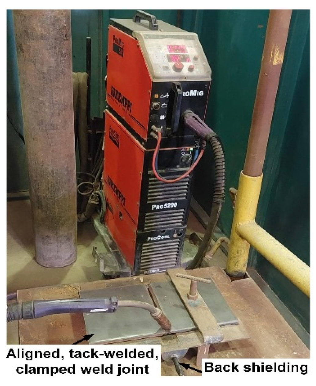
2. Materials and Methods
3. Results and Discussion
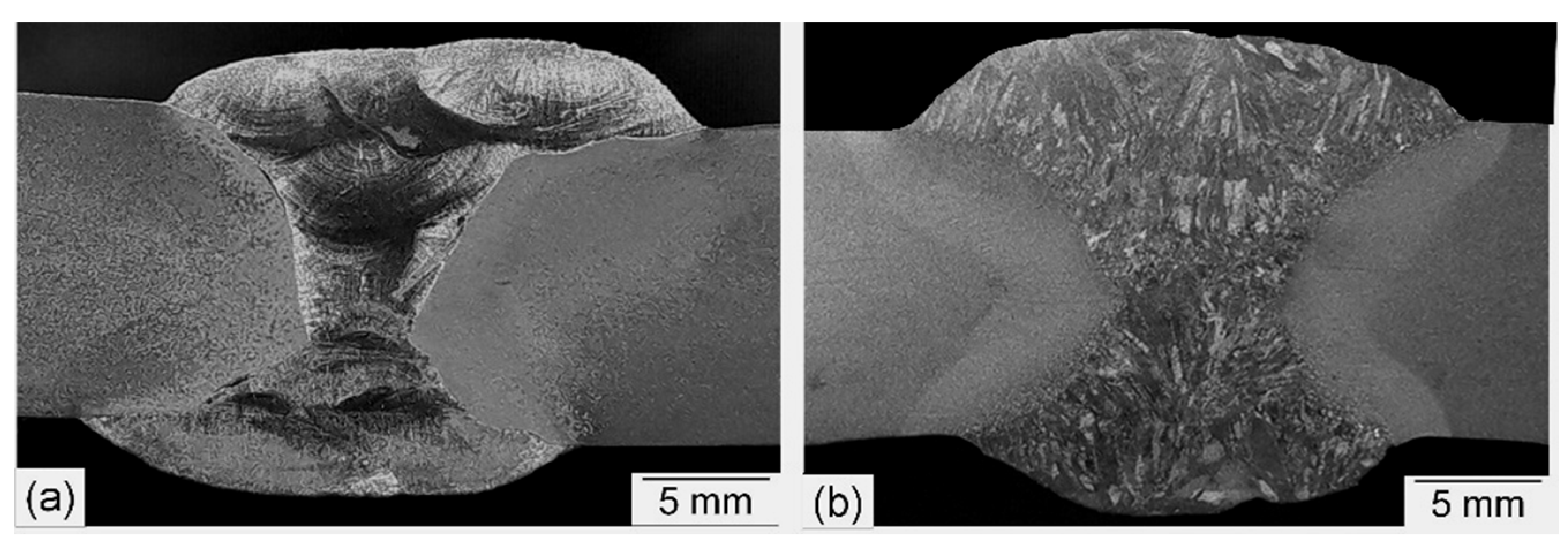
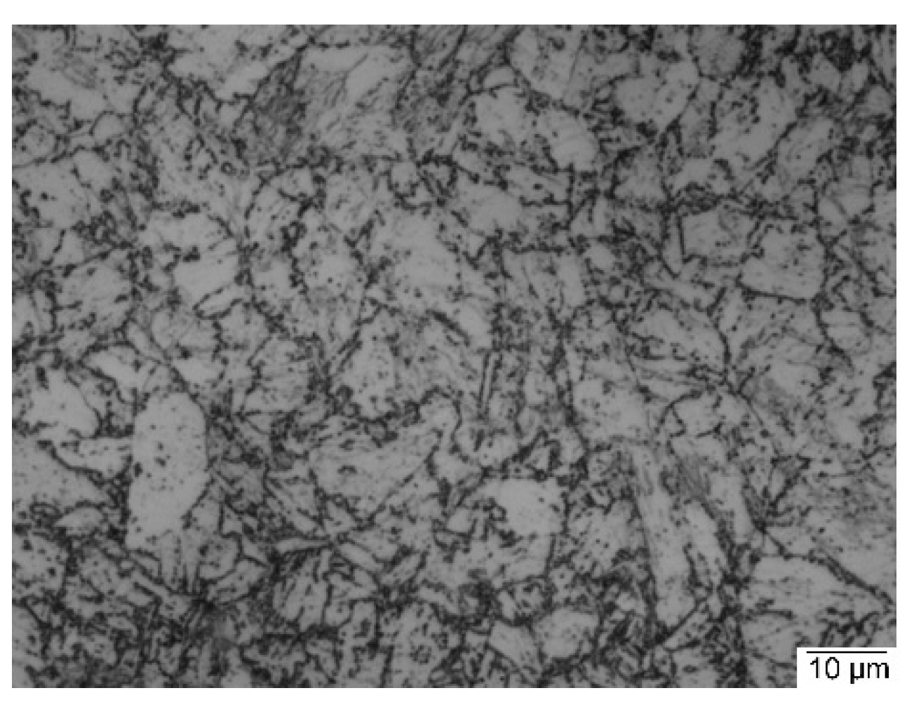
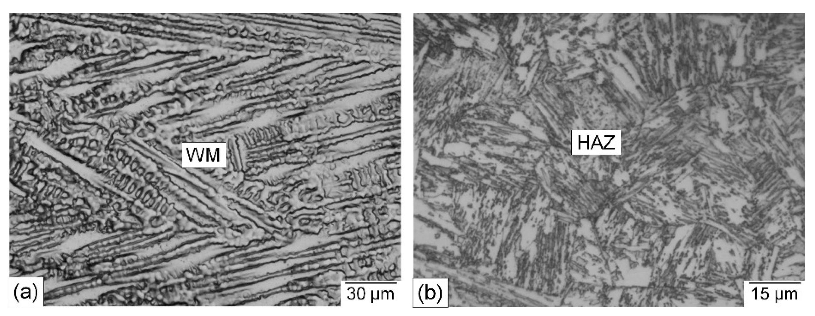
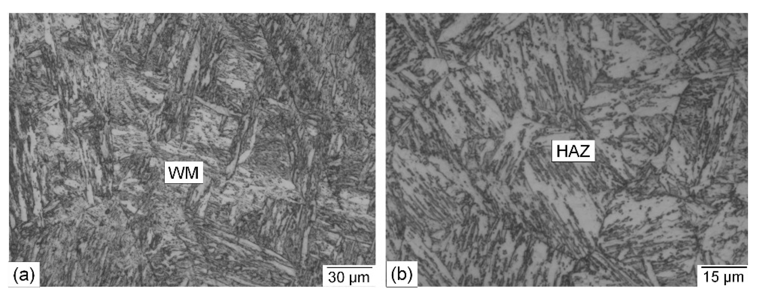
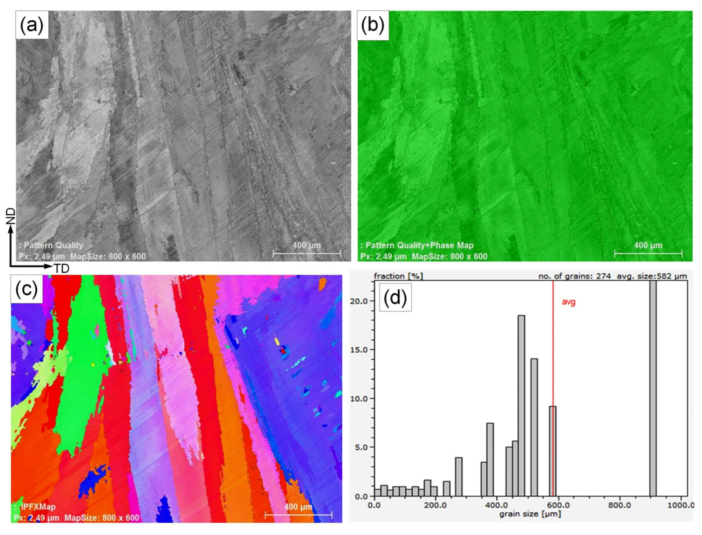
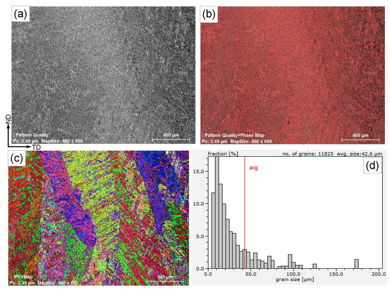
3.1. Metallurgical Examinations
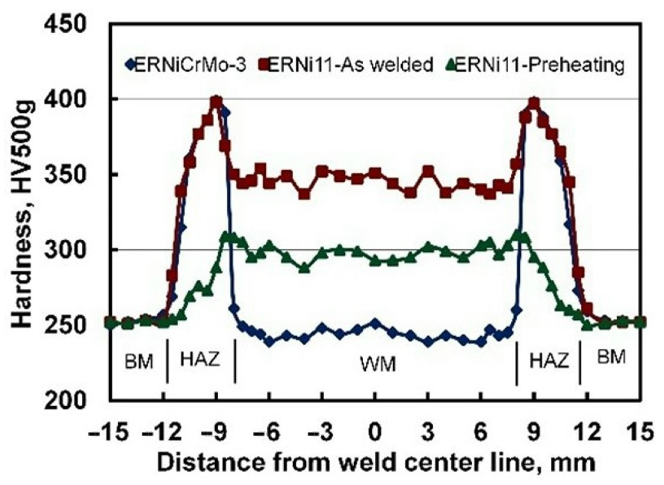
3.2. Hardness Measurements
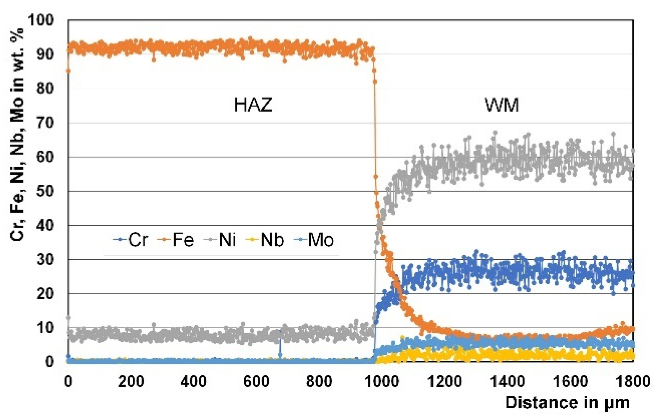
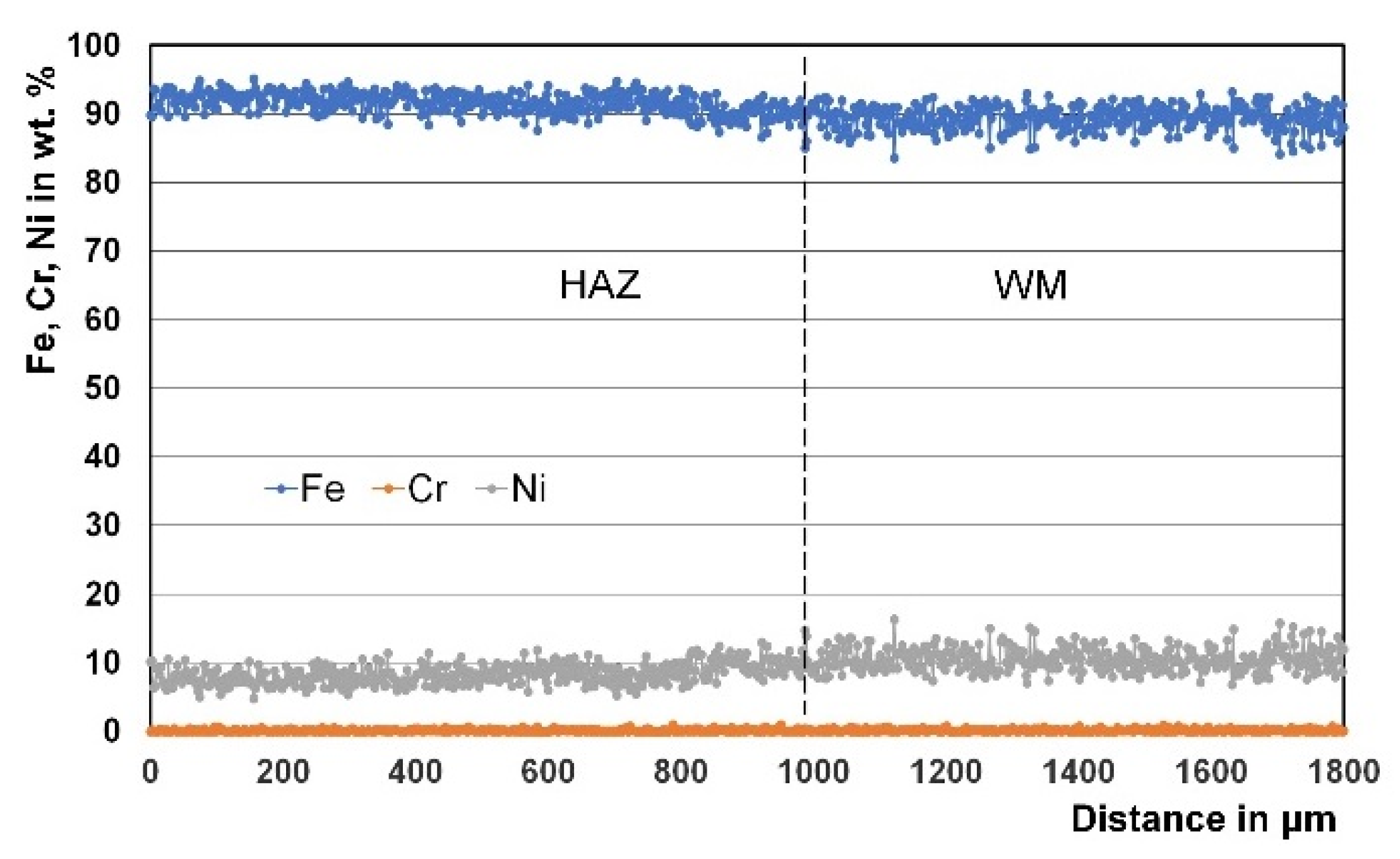
3.3. Micro Chemical Analysis
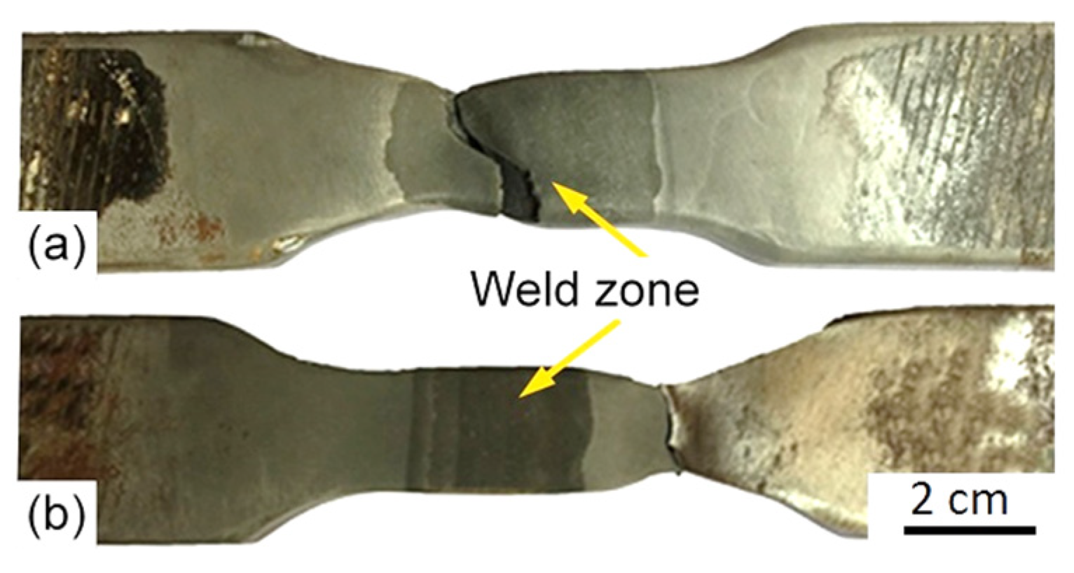
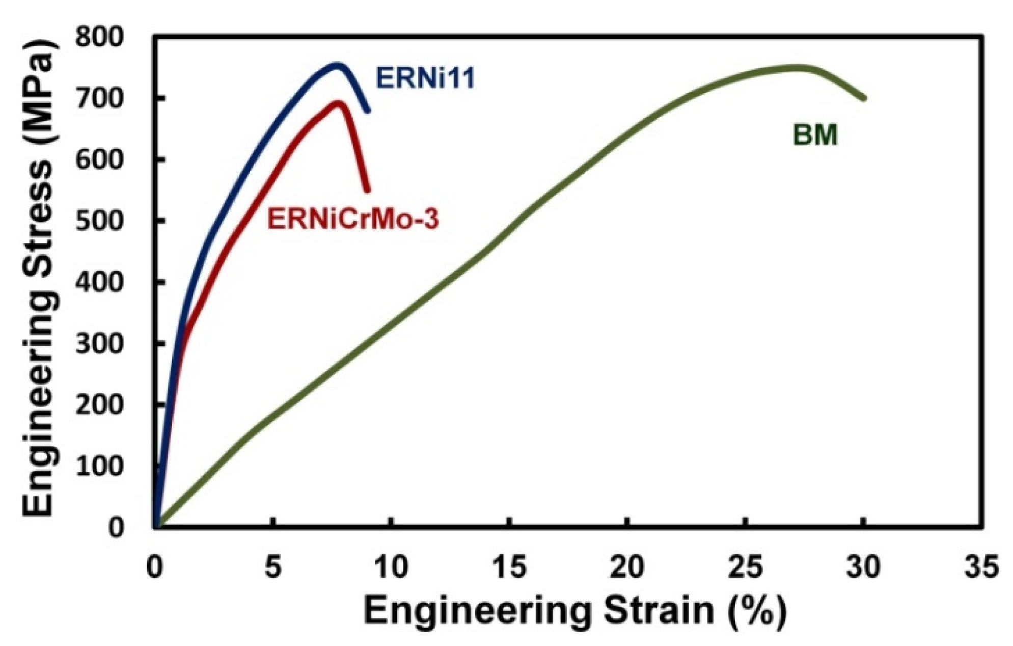
3.4. Mechanical Properties of Welded Joints
4. Conclusions
Author Contributions
Funding
Institutional Review Board Statement
Informed Consent Statement
Acknowledgments
Conflicts of Interest
References
- Furuya, H.; Kawabata, T.; Takahashi, Y.; Kamo, T.; Inoue, T.; Okushima, M.; Ando, R.; Onishi, K. Development of low-nickel steel for LNG storage tanks. In Proceedings of the 2013 International Conference and Exhibition on Liquefied Natural Gas, Houston, TX, USA, 16–19 April 2013. [Google Scholar]
- Ishimatu, J.; Kawabata, K.; Morita, H.; Ikkai, H.; Suetake, Y. Building of Advanced Large Sized Membrane Type LNG Carrier; Mitsubishi Heavy Industries Ltd.: Tokyo, Japan, 2004. [Google Scholar]
- Hoshio, M.; Saitoh, N.; Muraoka, H.; Saeki, O. Development of super-9%Ni steel plates with superior low-temperature toughness for LNG storage tanks. Nippon Steel Tech. Rep. 2004, 380, 17–20. [Google Scholar]
- Oh, D.J.; Lee, J.M.; Noh, B.J.; Kim, W.S.; Ando, R.; Matsumoto, T.; Kim, M.H. Investigation of fatigue performance of low temperature alloys for liquefied natural gas storage tanks. J. Mech. Eng. Sci. 2015, 229, 1300–1314. [Google Scholar] [CrossRef]
- Scheid, A.; Félix, L.M.; Martinazzi, D.; Renck, T.; Kwietniewski, C.E.F. The microstructure effect on the fracture toughness of ferritic Ni-alloyed steels. Mater. Sci. Eng. A 2016, 661, 96–104. [Google Scholar] [CrossRef]
- Kobelco. Kobelco’s welding consumables for LNG storage tanks made of 9%Ni steel. Kobelco Weld Today 2011, 14, 3–8. [Google Scholar]
- Mathers, G. Welding of Ferritic Cryogenic Steels; The Welding Institute: Cambridge, UK, 2012. [Google Scholar]
- Gustafsson, M.; Thuvander, M.; Bergqvist, E.L.; Keehan, E.; Karlsson, L. Effect of welding procedure on texture and strength of nickel-based WM. Sci. Technol. Weld. Jt. 2007, 12, 549–555. [Google Scholar] [CrossRef]
- Yoon, Y.K.; Kim, J.H.; Shim, K.T.; Kim, Y.K. Mechanical characteristics of 9%Ni steel welded joint for LNG storage tank at cryogenic. Int. J. Mod. Phys. 2012, 6, 355–360. [Google Scholar] [CrossRef]
- Mu, W.; Li, Y.; Cai, Y.; Wang, M. Cryogenic fracture toughness of 9%Ni steel flux cored arc welds. J. Mater. Process. Technol. 2018, 252, 804–812. [Google Scholar] [CrossRef]
- Jang, J.I.; Ju, J.B.; Lee, B.W.; Kwon, D.; Kim, W.S. Effects of microstructural change on fracture characteristics in coarse-grained heat-affected zones of QLT-processed 9%Ni steel. Mater. Sci. Eng. A 2003, 340, 68–79. [Google Scholar] [CrossRef]
- Mizumoto, M.; Motomatsu, R.; Nagasaki, H.; Iijima, T.; Kobayashi, K.; Mizo, Y. Development of submerged arc welding in vertical up position: A study on welding consumables for 9%Ni steel. J. Japan Weld. Soc. 2008, 82, 48–49. [Google Scholar]
- Park, J.Y.; Lee, J.M.; Kim, M.H. An investigation of the mechanical properties of a weldment of 7% nickel alloy steels. Metals 2016, 6, 285. [Google Scholar] [CrossRef] [Green Version]
- Bourges, P.; Malingraux, M. Fabrication and Welding of Thick plates in 9%Ni Cryogenic Steel; Industeel Co.: Le Creusot, France, 2008. [Google Scholar]
- Nippes, E.F.; Balaguer, J.P. A study of the weld heat-affected zone toughness of 9%Nickel steel. Weld. Res. 1986, 9, 237S–243S. [Google Scholar]
- Gook, S.; Forquer, M.; El-Batahgy, A.; Gumenyuk, A.; Rethmeier, M. Laser and hybrid laser-arc welding of cryogenic 9%Ni steel for construction of LNG storage tanks. In Proceedings of the 3rd International Conference in Africa and Asia on Welding and Failure Analysis of Engineering Materials, Luxor, Egypt, 2–5 November 2015. [Google Scholar]
- El-Batahgy, A.; Gumenyuk, A.; Gook, S.; Rethmeier, M. Comparison between GTA and laser beam welding of 9%Ni steel for critical cryogenic applications. J. Mater Process. Technol. 2018, 261, 193–201. [Google Scholar] [CrossRef]
- Wu, Y.; Cai, Y.; Sun, D.; Zhu, J.; Wu, Y. Microstructure and properties of high-power laser welding of SUS304 to SA553 for cryogenic applications. J. Mater. Process. Technol. 2015, 225, 56–66. [Google Scholar] [CrossRef]
- Huang, Z.; Cai, Y.; Mu, W.; Li, Y.; Hua, X. Effects of laser energy allocation on weld formation of 9%Ni steel made by narrow gap laser welding filled with nickel based alloy. J. Laser Appl. 2018, 30, 032013. [Google Scholar] [CrossRef]
- El-Batahgy, A.; Khourshid, A.; Sharef, T. Effect of laser beam welding parameters on microstructure and properties of duplex stainless steel. Mater. Sci. Appl. 2011, 10, 1443–1451. [Google Scholar] [CrossRef] [Green Version]
- Quiroz, V.; Gumenyuk, A.; Rethmeier, M. Laser beam weldability of high-manganese austenitic and duplex stainless steel sheets. Weld. World 2012, 56, 9–20. [Google Scholar] [CrossRef]
- El-Batahgy, A.; Tsuboi, A. Effect of welding process type on mechanical and corrosion properties of SUS329J4L duplex stainless steel. J. Strength Fract. Complex. 2013, 8, 189–203. [Google Scholar] [CrossRef]
- El-Batahgy, A.; DebRoy, T. Nd-YAG laser beam and GTA welding of Ti-6Al-4V alloy. Int. J. Eng. Tech. Res. 2014, 12, 43–50. [Google Scholar]
- Stavridis, J.; Papacharalampopoulos, A.; Stavropoulos, P. Quality assessment in laser welding: A critical review. Int. J. Adv. Manuf. Technol. 2018, 94, 1825–1847. [Google Scholar] [CrossRef]
- Verma, J.; Taiwade, R.V. Effect of welding processes and conditions on the microstructure, mechanical properties and corrosion resistance of duplex stainless-steel weldments–A review. J. Manuf. Processes. 2017, 25, 134–152. [Google Scholar]
- Agusa, K.; Kosho, M.; Nishiyama, N.; Kitagawa, M.; Nakazawa, M. Production of 9%Ni steel UOE pipe with ferritic filler submerged arc welding. Trans. Iron Steel Inst. Jpn. 1986, 26, 359–366. [Google Scholar] [CrossRef] [Green Version]
- Koshiga, F.; Tanaka, J.; Watanabe, I.; Takamura, T. Matching ferritic consumable welding of 9%Nickel steel to enhance safety and economy. Weld. J. 1984, 4, 105s–115s. [Google Scholar]
- El-Batahgy, A.; Saiyah, A.; Khafagi, S.; Gumenyuk, A.; Gook, S.; Rethmeier, M. Shielded metal arc welding of 9%Ni steel using matching ferritic filler metal. Sci. Technol. Weld. Join. 2021, 26, 116–122. [Google Scholar] [CrossRef]
- Li, X.; Chen, Y.; Hao, B.; Han, Y.; Chu, Y.; Zhang, J. The microstructure and microscopic mechanical performance of welded joint for 9%Ni steel using nickel-based filler metal. Mat. Res. 2021, 5, 117–125. [Google Scholar]
- Zhao, X.-Q.; Pan, T.; Wang, Q.-F.; Su, H.; Yang, C.-F.; Yang, Q.-X. Effect of tempering temperature on microstructure and mechanical properties of steel containing Ni of 9%. J. Iron Steel Res. Int. 2011, 18, 47–51. [Google Scholar] [CrossRef]
- Gook, S.; Krieger, S.; Gumenyuk, A.; El-Batahgy, A.; Rethmeier, M. Notch impact toughness of laser beam welded thick sheets of cryogenic nickel alloyed steel X8Ni9. Procedia CIRP 2020, 94, 627–631. [Google Scholar] [CrossRef]


| Chemical Composition (wt.%) | |||||||||
|---|---|---|---|---|---|---|---|---|---|
| C | Si | Mn | P | S | Al | Ni | Cr | Cu | Fe |
| 0.07 | 0.20 | 0.57 | 0.003 | 0.001 | 0.02 | 9.15 | 0.03 | 0.02 | balance |
| Mechanical properties | |||||||||
| Yield strength (MPa) | Tensile strength (MPa) | Elongation (%) | Hardness (HV) | Impact absorbed energy at −196 °C (−320 °F) | |||||
| 671 | 745 | 28 | 253 | 178 | |||||
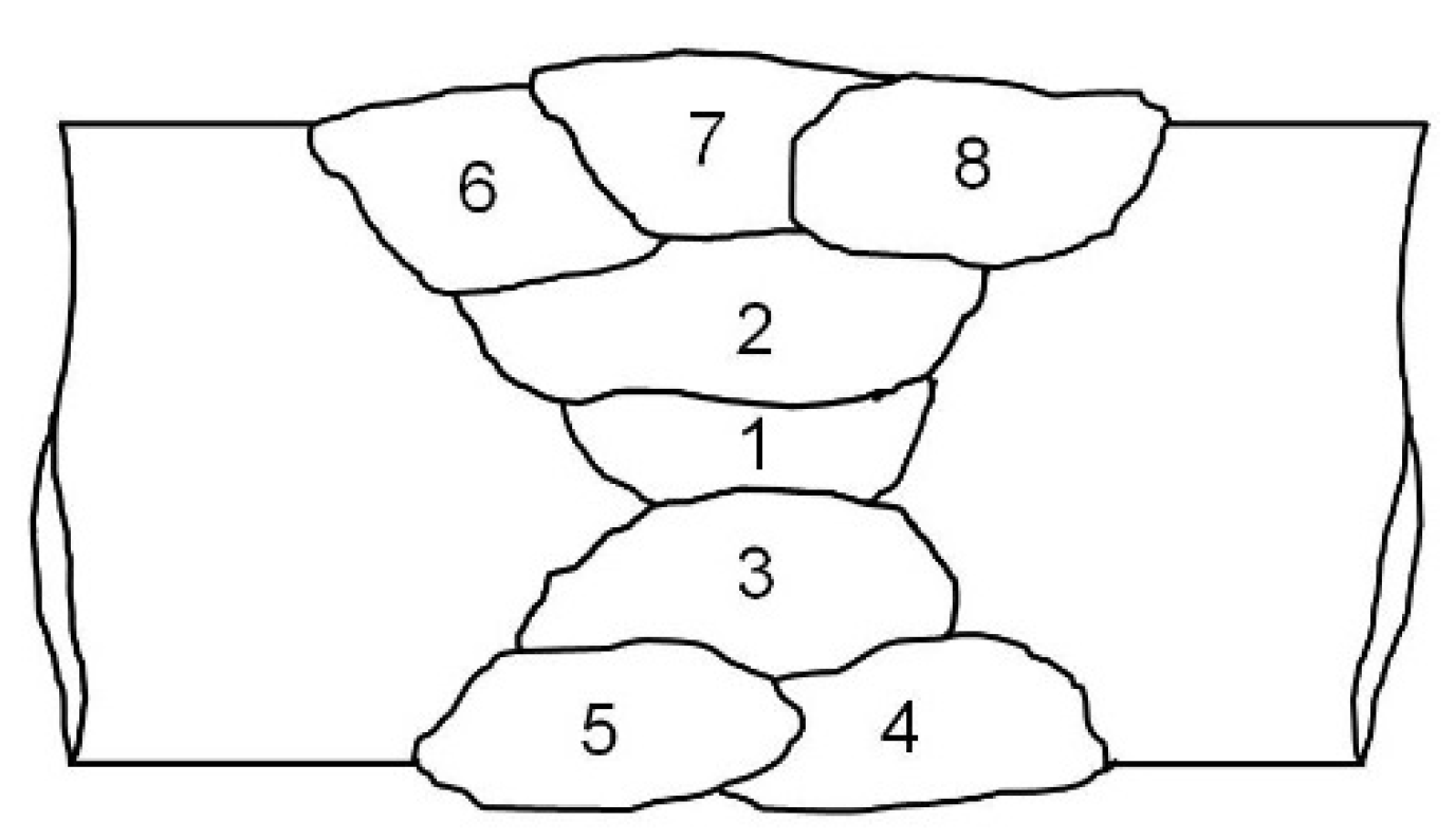
| Pass No. | Current (A) | Voltage (V) | Speed (mm/min) | HI (kJ/mm) |
|---|---|---|---|---|
| 1 | 198 | 29 | 222 | 1.55 |
| 2 | 198 | 29 | 210 | 1.64 |
| 3 | 198 | 29 | 210 | 1.64 |
| 4 | 198 | 29 | 224 | 1.54 |
| 5 | 198 | 29 | 224 | 1.54 |
| 6 | 198 | 29 | 230 | 1.50 |
| 7 | 198 | 29 | 230 | 1.50 |
| 8 | 198 | 29 | 230 | 1.50 |
Publisher’s Note: MDPI stays neutral with regard to jurisdictional claims in published maps and institutional affiliations. |
© 2022 by the authors. Licensee MDPI, Basel, Switzerland. This article is an open access article distributed under the terms and conditions of the Creative Commons Attribution (CC BY) license (https://creativecommons.org/licenses/by/4.0/).
Share and Cite
El-Batahgy, A.-M.; Elkousy, M.R.; Al-Rahman, A.A.; Gumenyuk, A.; Rethmeier, M.; Gook, S. Retaining Mechanical Properties of GMA-Welded Joints of 9%Ni Steel Using Experimentally Produced Matching Ferritic Filler Metal. Materials 2022, 15, 8538. https://doi.org/10.3390/ma15238538
El-Batahgy A-M, Elkousy MR, Al-Rahman AA, Gumenyuk A, Rethmeier M, Gook S. Retaining Mechanical Properties of GMA-Welded Joints of 9%Ni Steel Using Experimentally Produced Matching Ferritic Filler Metal. Materials. 2022; 15(23):8538. https://doi.org/10.3390/ma15238538
Chicago/Turabian StyleEl-Batahgy, Abdel-Monem, Mohamed Raafat Elkousy, Ahmed Abd Al-Rahman, Andrey Gumenyuk, Michael Rethmeier, and Sergej Gook. 2022. "Retaining Mechanical Properties of GMA-Welded Joints of 9%Ni Steel Using Experimentally Produced Matching Ferritic Filler Metal" Materials 15, no. 23: 8538. https://doi.org/10.3390/ma15238538