
Effect of Pro-Ecological Cooling and Lubrication Methods on the Sharpening Process of Planar Blades Used in Food Processing
 , , , and
Abstract
:1. Introduction
2. Materials and Methods
3. Results and Discussion
- amplitude (arithmetic mean deviation of the surface Sa, total height of the surface St);
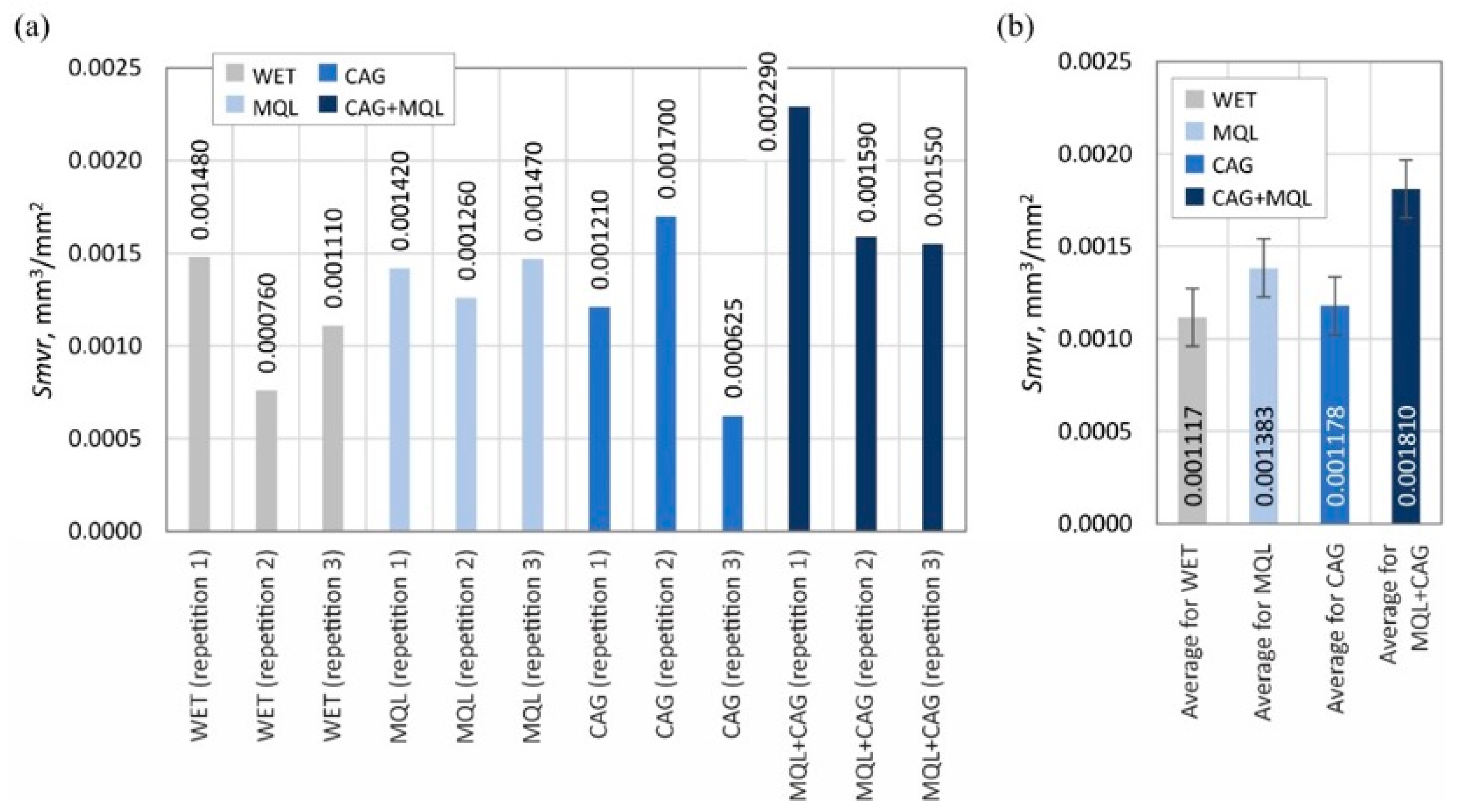
- area and volume (mean void volume ratio Smvr);
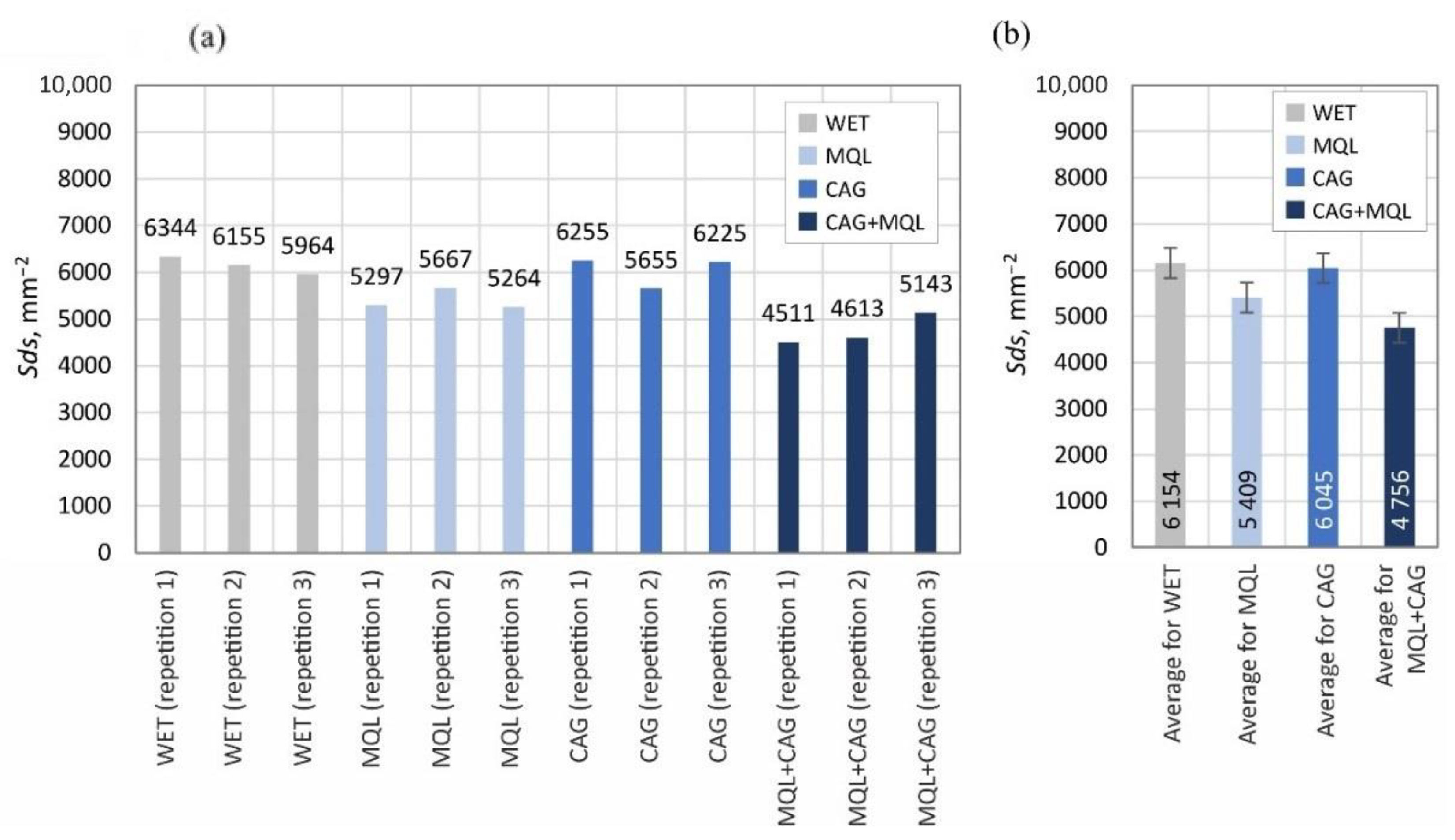
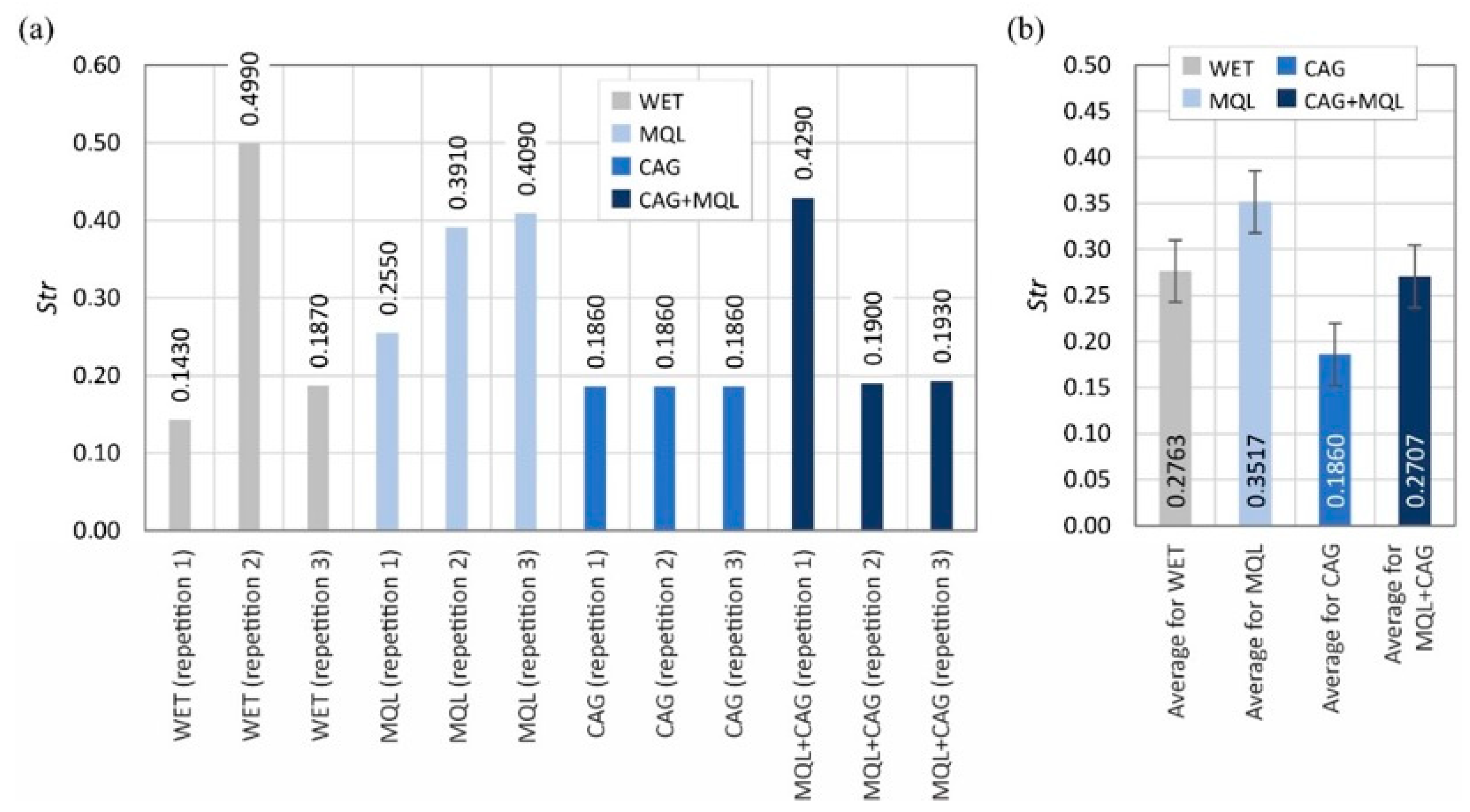
- spatial (density of summits of the surface Sds, texture aspect ratio of the surface Str);
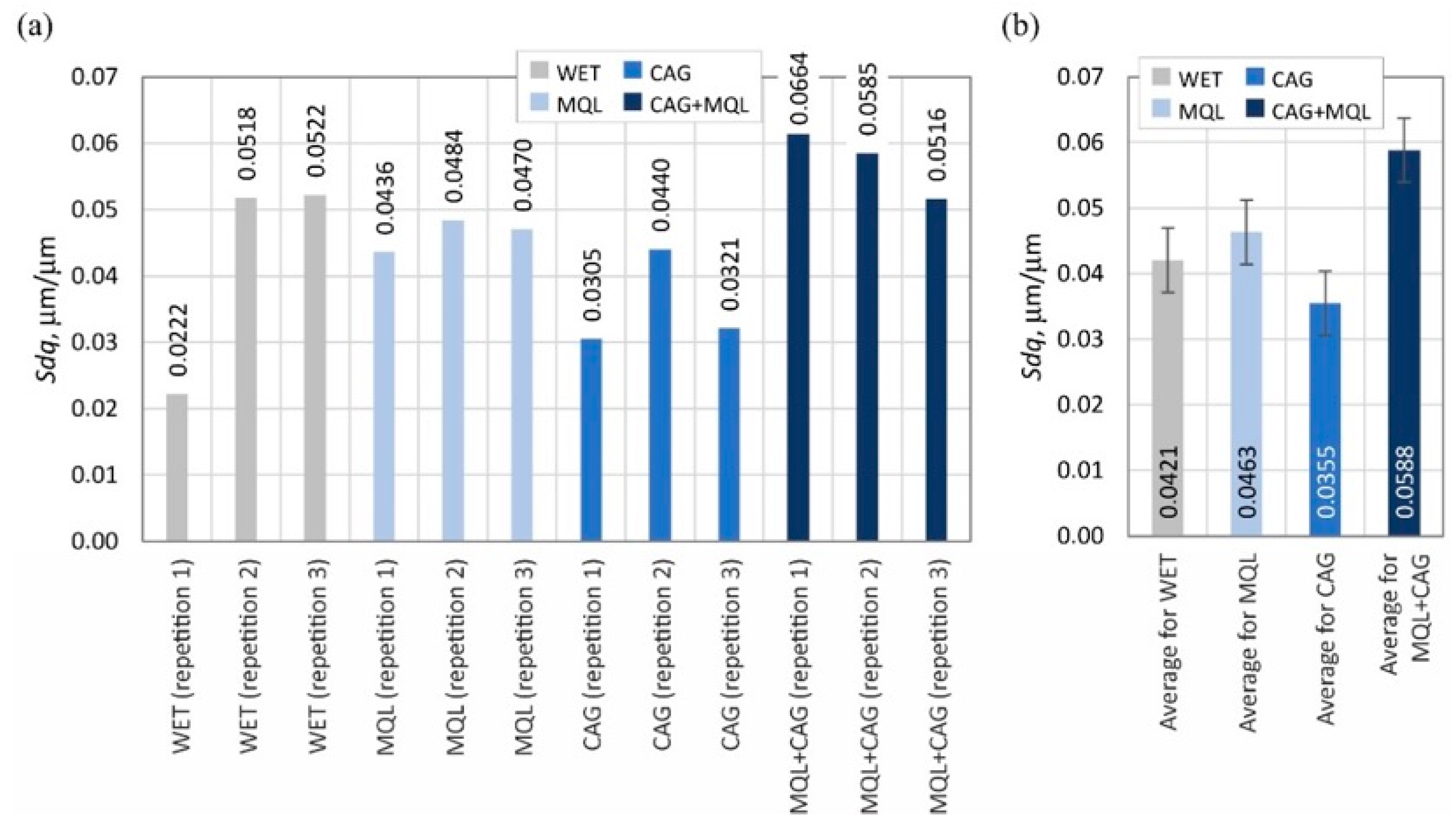
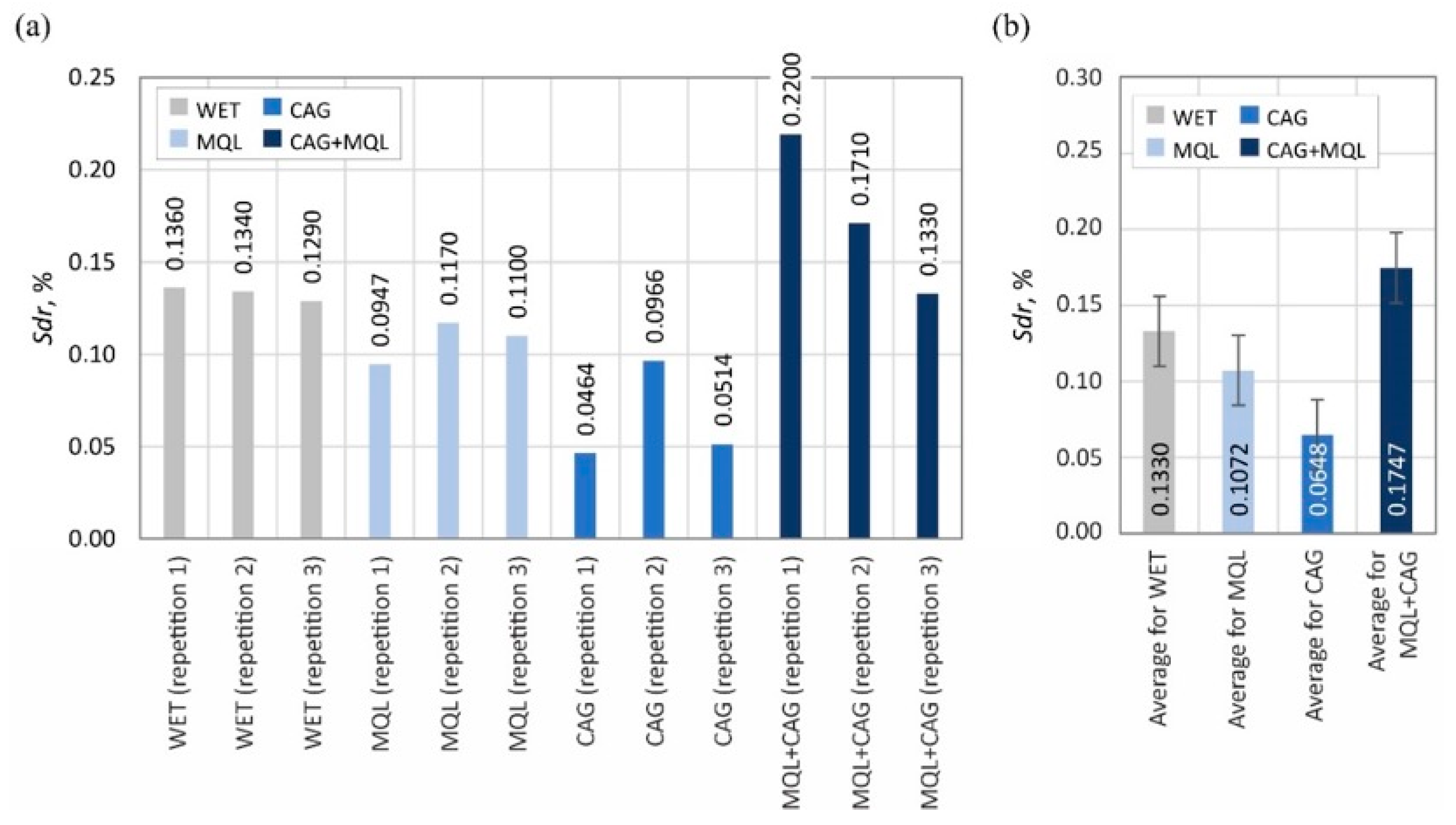
- hybrid (root-mean-square slope of the surface Sdq, developed interfacial area ratio Sdr);
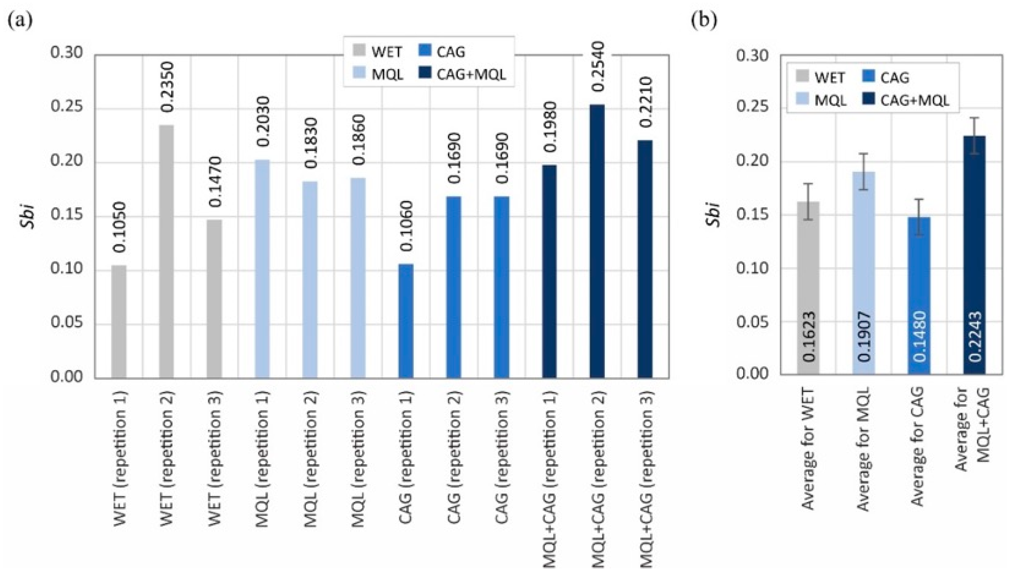
- functional (bearing index Sbi).
4. Conclusions
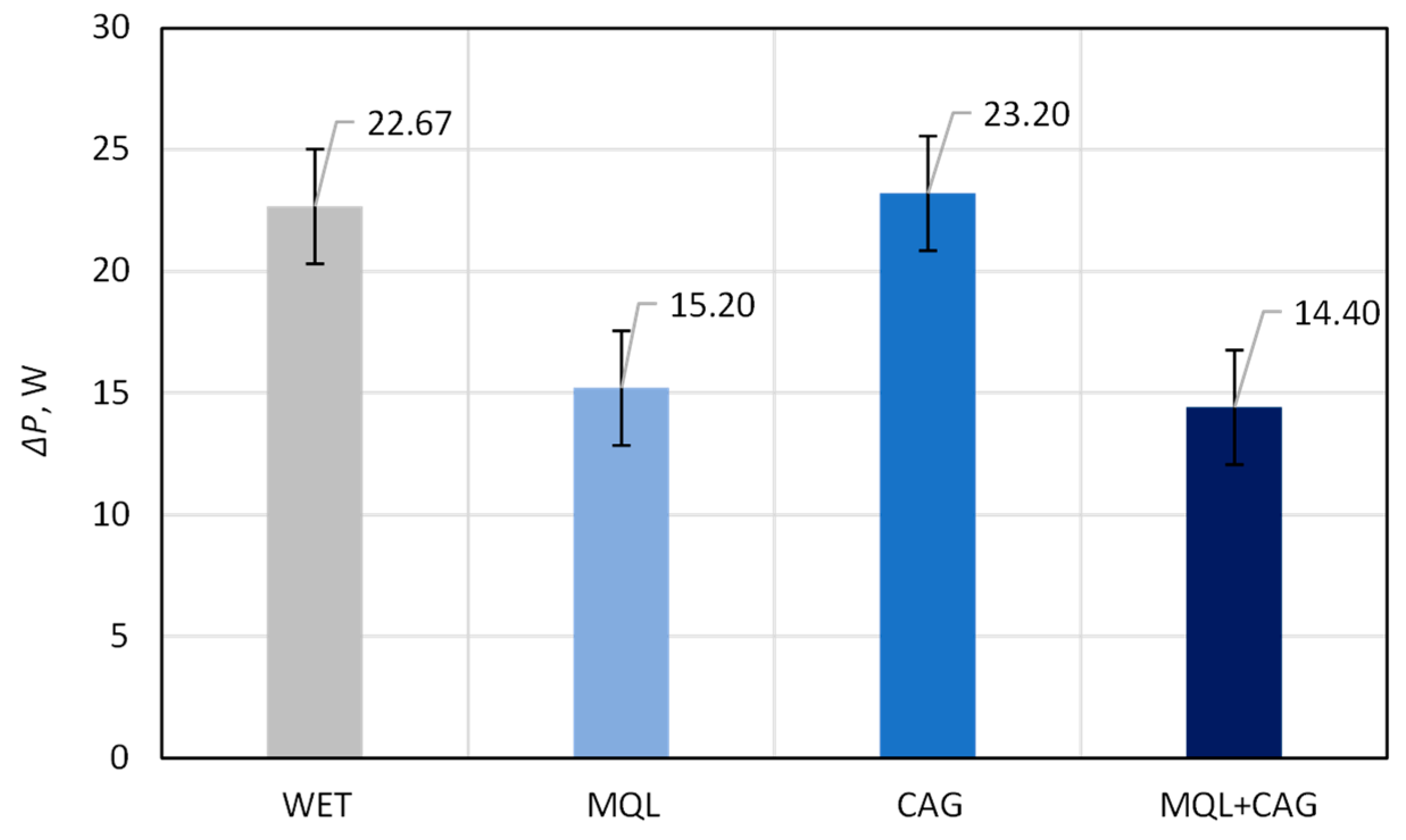
- Relatively small values of the grinding power gain ΔP were measured when the grinding process was carried out under MQL conditions (ΔP = 15.20 W) and using the hybrid method MQL + CAG (ΔP = 14.40 W). In the case of the WET and CAG methods, the ΔP values were about 50–60% higher, respectively ΔP = 22.67 W and ΔP = 23.20 W. The application of the MQL method and the hybrid MQL + CAG method provided a very good realization of the lubricating function so that the share of friction of dulled cutting vertices against the workpiece surface is reduced, which manifests itself in the reduction of the grinding force and the correlated grinding power.
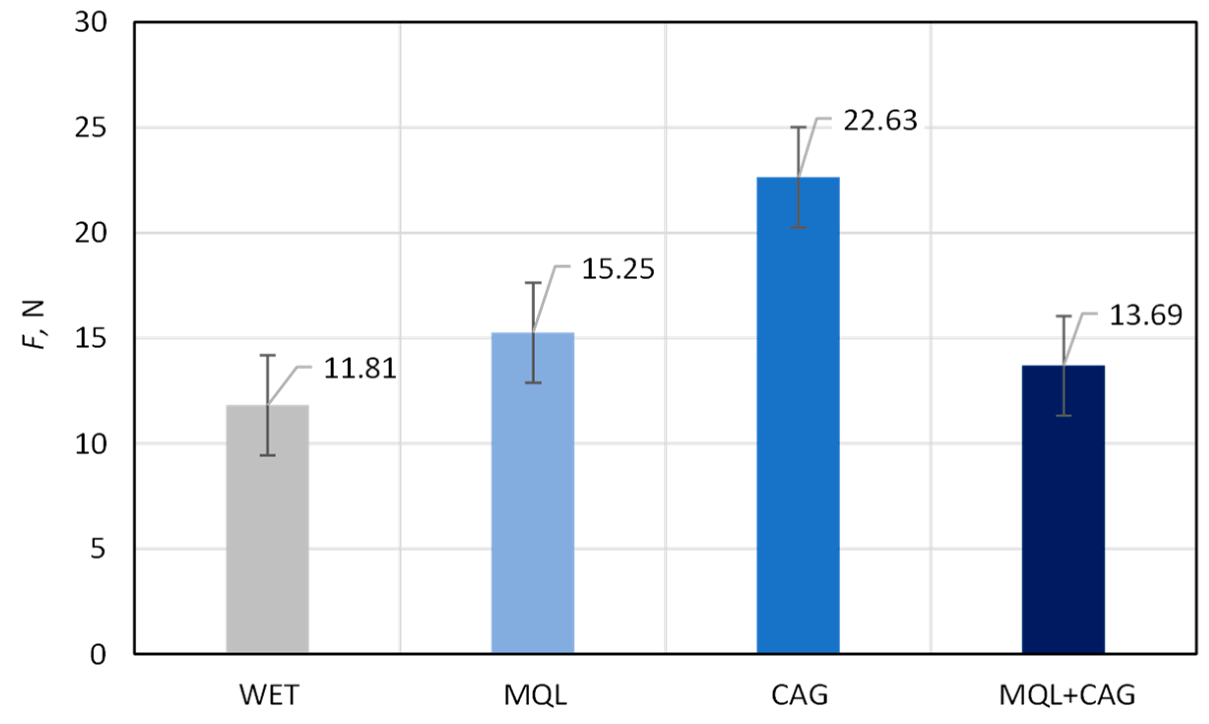
- Beneficial cutting properties (manifested by relatively small F values) were obtained by using flooding cooling WET (F = 11.81 N), MQL (F = 15.25 N) and the hybrid method MQL + CAG (F = 13.69 N) in the grinding process. In the case of grinding under cooled compressed air delivery conditions, the average cutting force was as much as 91.6% higher (F = 22.63 N) compared to the result obtained for the most favorable flooding method, demonstrating the insufficient quality of the blade shaped under such conditions.
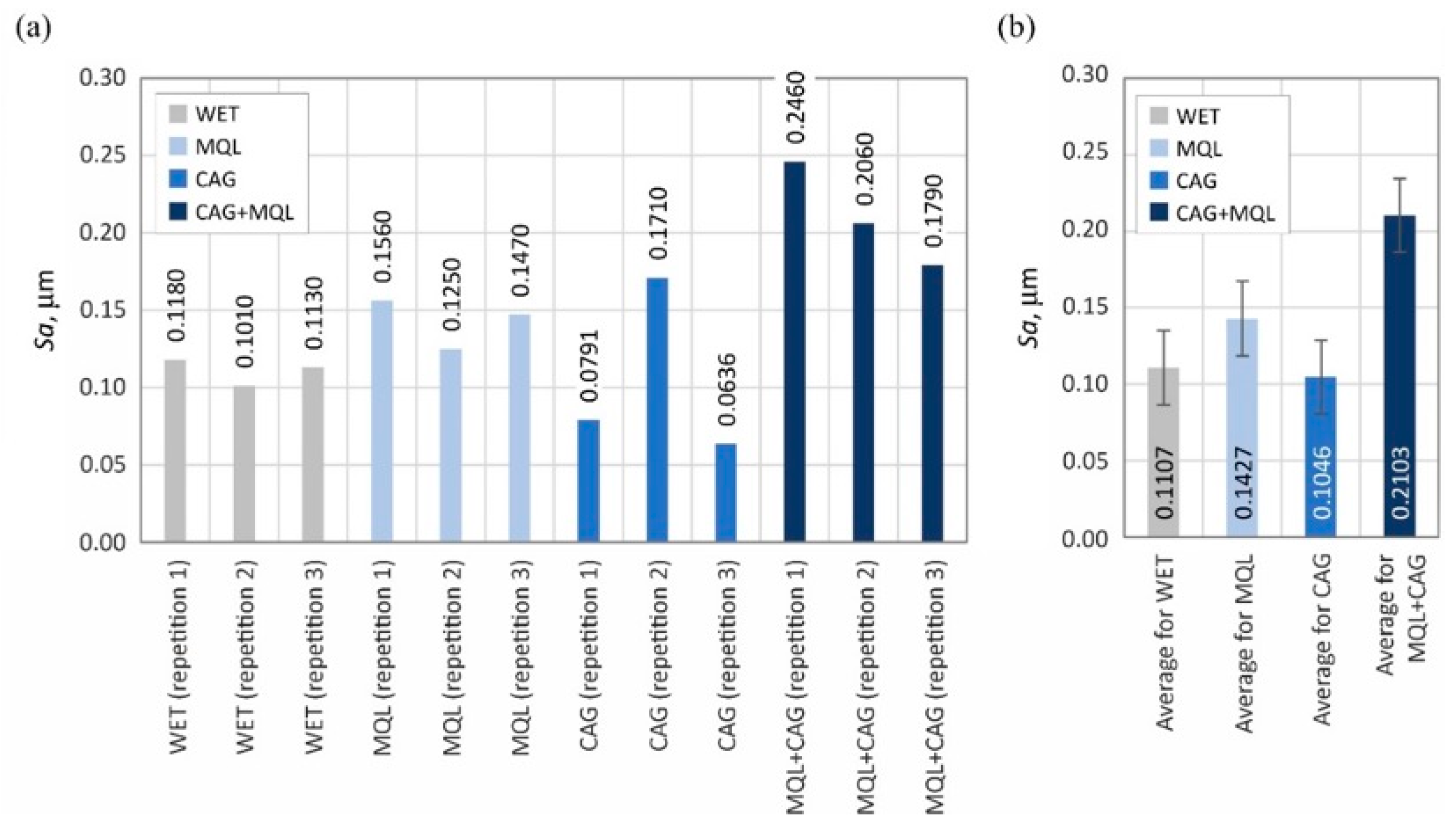
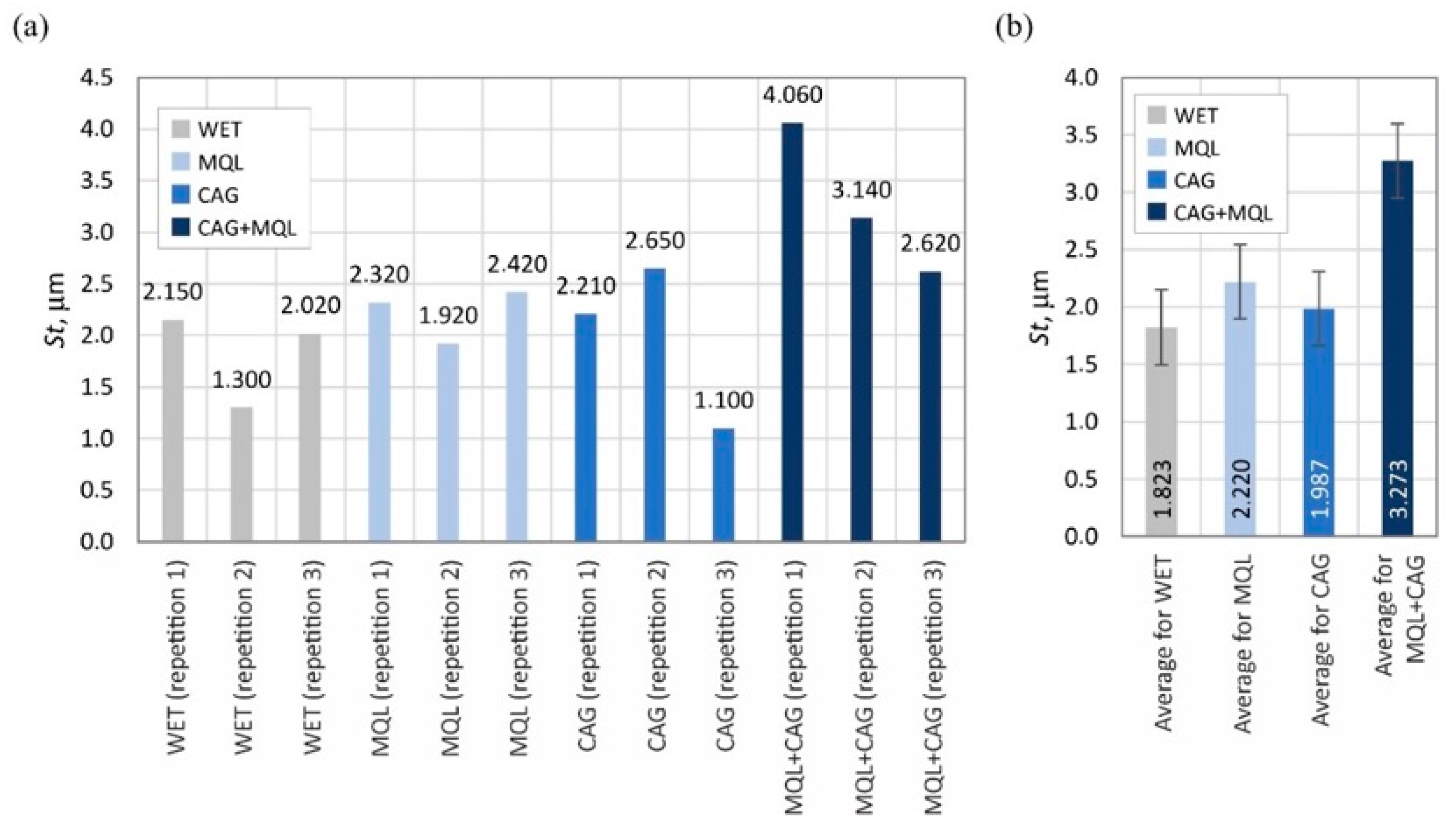
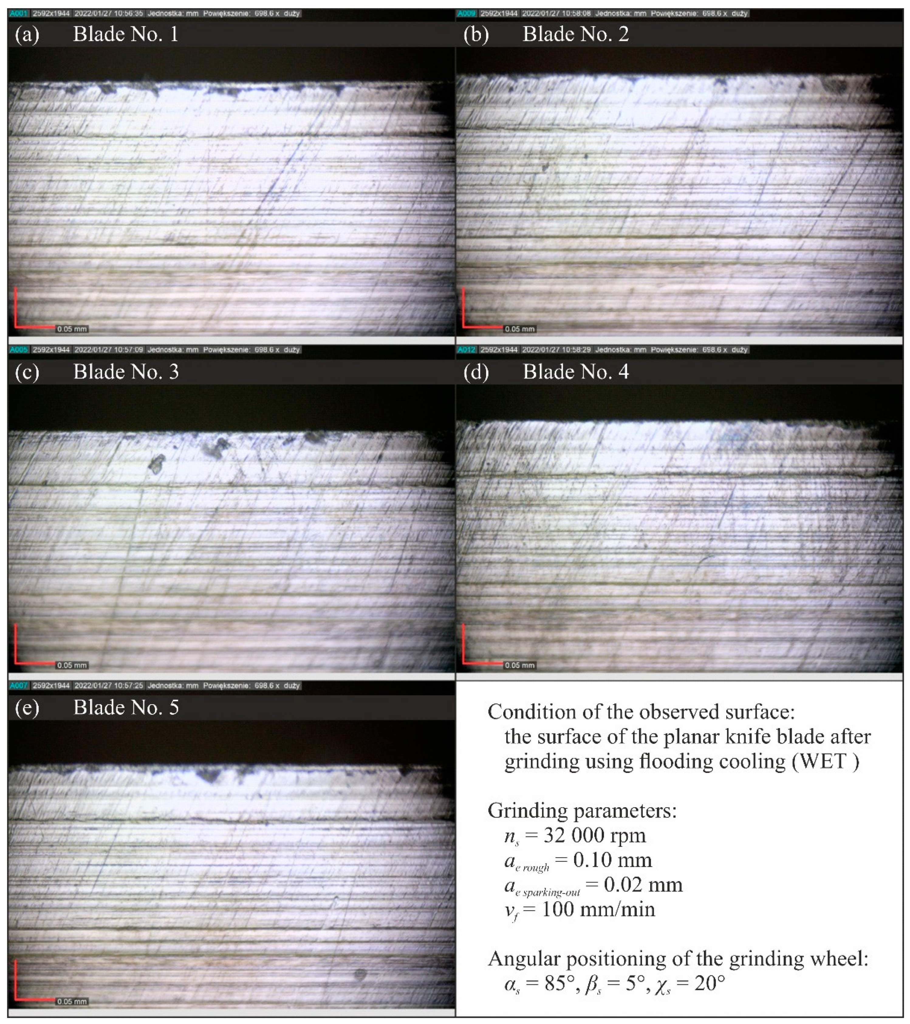
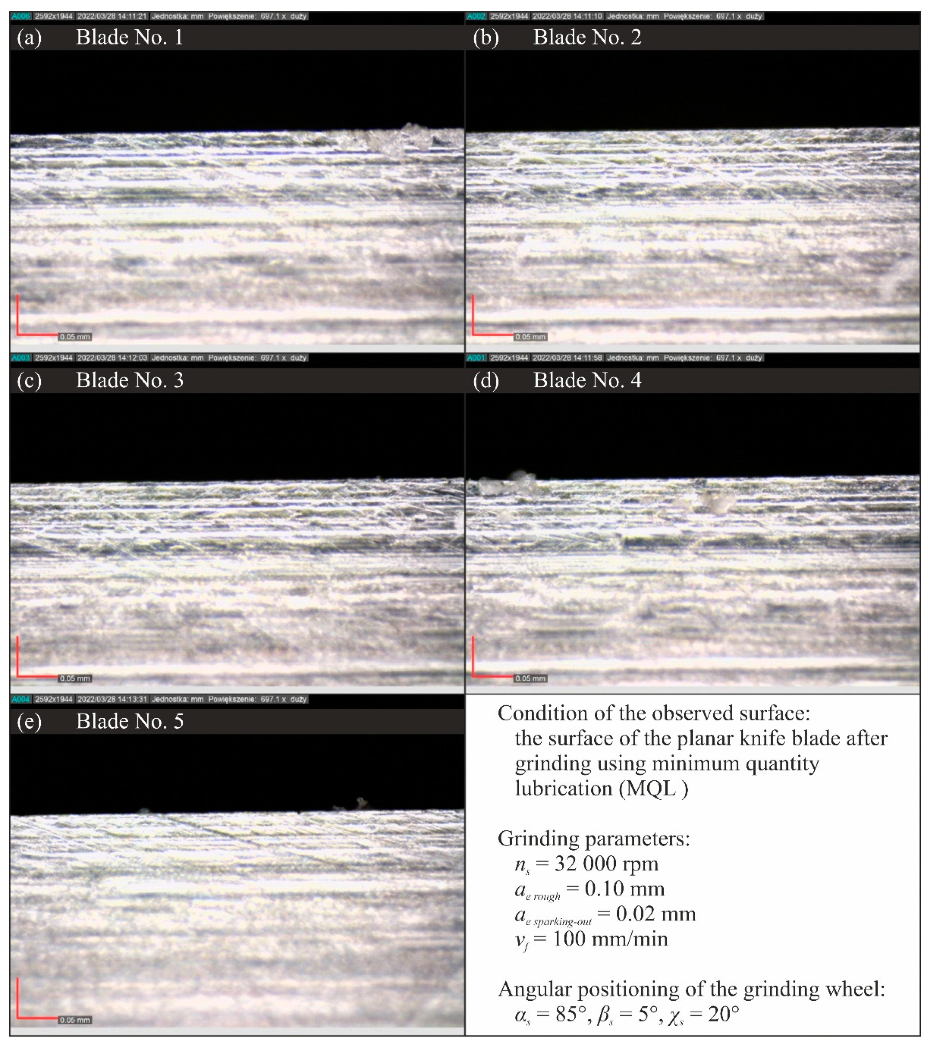
- The results of the analysis of selected parameters of the surface texture of the planar blade led to the conclusion that the application of the WET flooding method and MQL made it possible to shape the surfaces of the blade with a similar geometric structure.
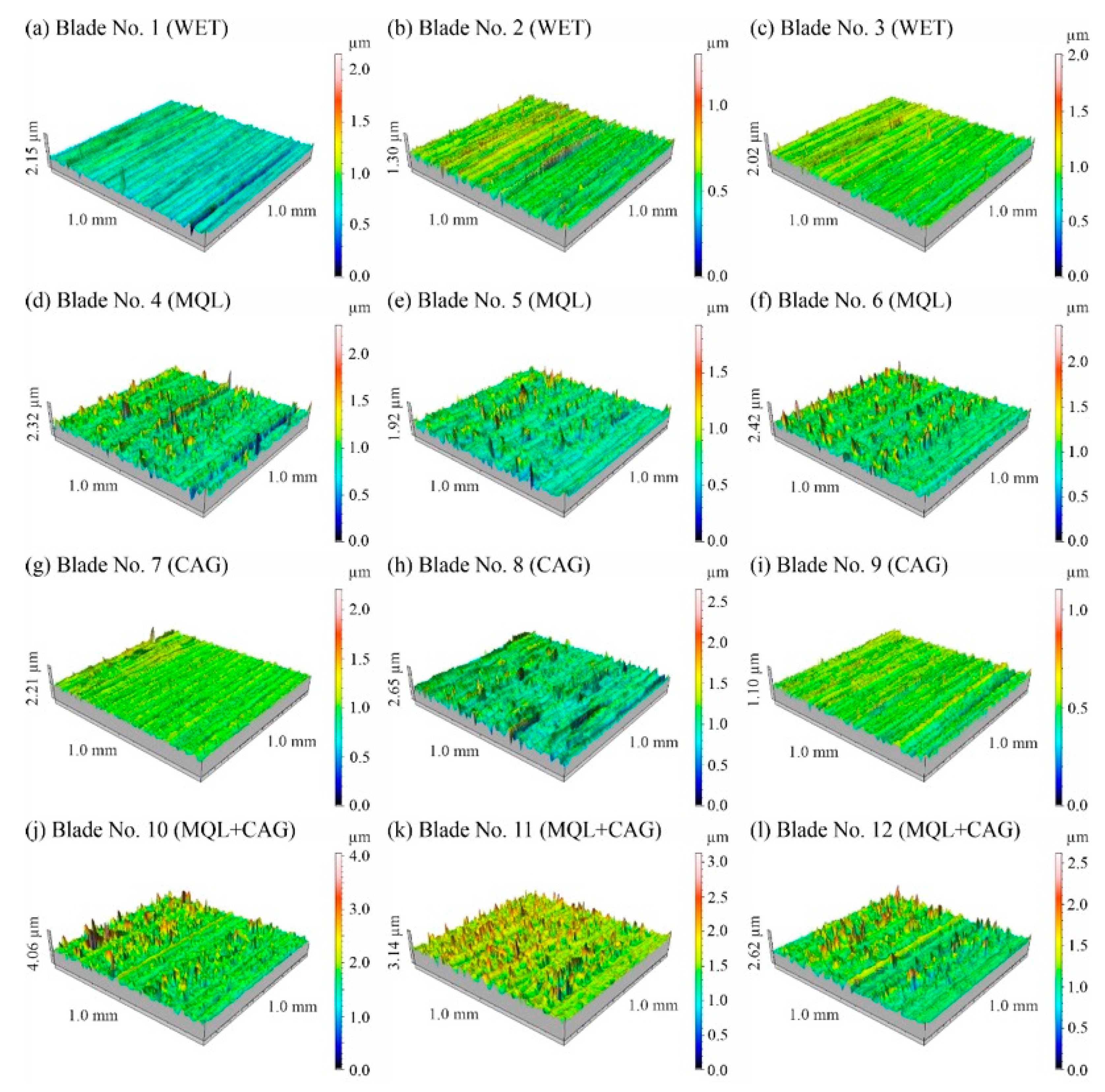
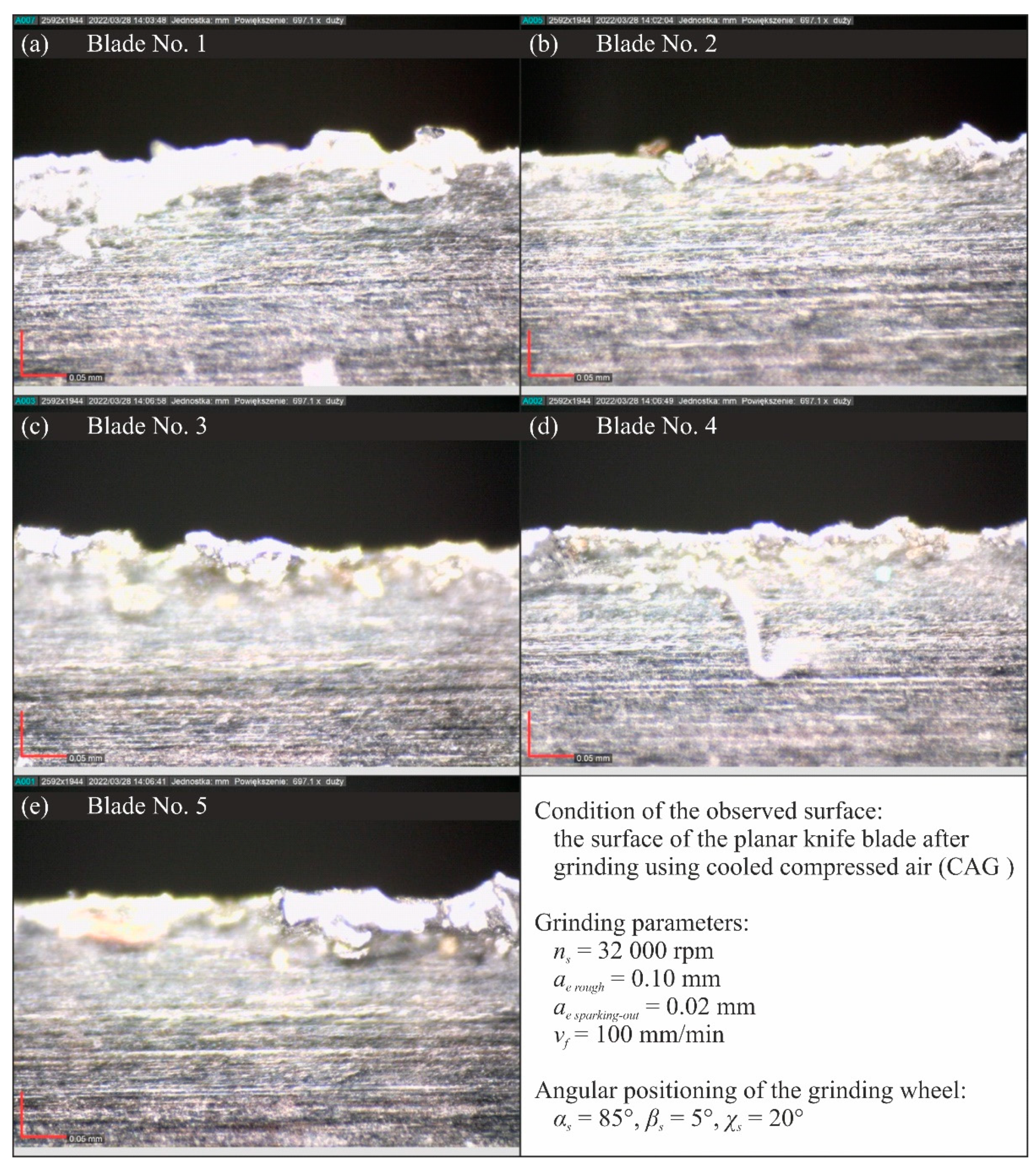
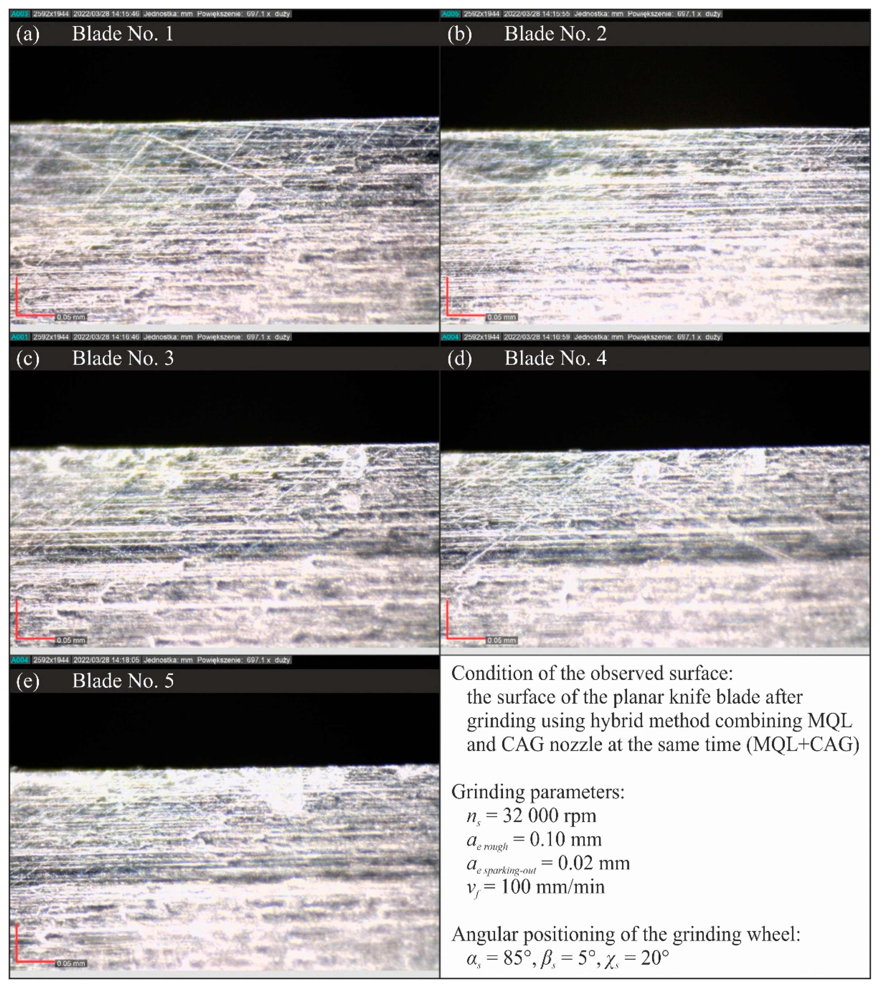
- Analysis of microscopic images showed a very similar condition of the surfaces of blades shaped under conditions of application of the WET, MQL and MQL + CAG methods. Against this background, the views of the surfaces of blades shaped under the conditions of delivering compressed cooled air with a CAG nozzle stood out clearly, which were characterized by a very large rewind and visible unremoved chips adhered to the blade, as well as numerous chippings of the blade. These features confirm previous conclusions about unfavorable thermal conditions in the grinding zone under CAG cooling conditions causing plasticization of the shaped blade.
- By selecting the cooling and lubrication conditions of the grinding zone, the functional characteristics of the blade surface can be significantly influenced, which affects the measured values of the cutting force and should potentially also affect the intensity of wear phenomena and, ultimately, the life of the blades in the process of skinning flat fish.
- A comprehensive comparison of test results on grinding power gain ΔP, cutting force F, and surface texture suggest that the most favorable sharpening results were obtained using an environmentally friendly MQL method of cooling and lubricating the grinding zone.
Author Contributions
Funding
Institutional Review Board Statement
Informed Consent Statement
Data Availability Statement
Conflicts of Interest
References
- McCarthy, C.T.; Hussey, M.; Gilchrist, M.D. On the sharpness of straight edge blades in cutting soft solids: Part I—indentation experiments. Eng. Fract. Mech. 2007, 74, 2205–2224. [Google Scholar] [CrossRef]
- Marsot, J.; Claudon, L.; Jacqmin, M. Assessment of knife sharpness by means of a cutting force measuring system. Appl Ergon. 2007, 38, 83–89. [Google Scholar] [CrossRef] [PubMed]
- McGorry, R.W.; Dowd, P.C.; Dempsey, P.G. A technique for field measurement of knife sharpness. Appl. Ergon. 2005, 36, 635–640. [Google Scholar] [CrossRef] [PubMed]
- Claudon, L.; Marsot, J. Effect of knife sharpness on upper limb biomechanical stresses—A laboratory study. Int. J. Ind. Ergon. 2006, 36, 239–246. [Google Scholar] [CrossRef]
- McGorry, R.W.; Dowd, P.C.; Dempsey, P. G The effect of blade finish and blade edge angle on forces used in meat cutting operations. Appl Ergon. 2005, 36, 71–77. [Google Scholar] [CrossRef]
- Verhoeven, J.D. Experiments on Knife Sharpening; Department of Materials Science, Engineering Iowa State University: Ames, IA, USA, 2004; Available online: https://www.tf.uni-kiel.de/matwis/amat/iss/kap_c/articles/verhoeven_sharpening.pdf (accessed on 24 May 2022).
- McCarthy, C.T.; Ni Annaidh, N.; Gilchrist, M.D. On the sharpness of straight edge blades in cutting soft solids: Part II—Analysis of blade geometry. Eng. Fract. Mech. 2010, 77, 437–451. [Google Scholar] [CrossRef]
- Krejcie, A.J.; Kapoor, S.G.; Devor, R.E. A hybrid process for manufacturing surgical-grade knife blade cutting edges from bulk metallic glass. J. Manuf. Process. 2012, 14, 26–34. [Google Scholar] [CrossRef]
- Klocke, F. Manufacturing Processes 2: Grinding, Honing, Lapping; Springer: Berlin, Germany, 2009. [Google Scholar]
- Marinescu, I.D.; Rowe, W.B.; Dimitrov, B.; Inasaki, I. Tribology of Abrasive Machining Processes; William Andrew Publishing: Norwich, NY, USA, 2004. [Google Scholar]
- Ahmed, L.S.; Govindaraju, N.; Kumar, M.P. Experimental investigations on cryogenic cooling in the drilling of Titanium alloy. Mater. Manuf. Process. 2016, 31, 603–607. [Google Scholar] [CrossRef]
- Cordes, S.; Hübner, F.; Schaarschmidt, T. Next generation high performance cutting by use of carbon dioxide as cryogenics. Procedia CIRP 2014, 14, 401–405. [Google Scholar] [CrossRef] [Green Version]
- Dhar, N.R.; Kishore, N.S.V.; Paul, S.; Chattopadhyay, A.B. The effects of cryogenic cooling on chips and cutting forces in turning AISI 1040 and AISI 4320 steels. Proc. Inst. Mech. Eng. B. J. Eng. Manuf. 2002, 216, 713–724. [Google Scholar] [CrossRef]
- Guitouni, A.; Chaieb, I.; Rhouma, A.B.; Fredj, N.B. Effects of jet pressure on the ground surface quality and CBN wheel wear in grinding AISI 690 nickel-based superalloy. J. Mater. Eng. Perform. 2016, 25, 5055–5064. [Google Scholar] [CrossRef]
- Jerold, B.D.; Kumar, M.P. Machining of AISI 316 stainless steel under carbon-di-oxide cooling. Mater. Manuf. 2012, 27, 1059–1065. [Google Scholar] [CrossRef]
- Manimaran, G.; Pradeep kumar, M.; Venkatasamy, R. Influence of cryogenic cooling on surface grinding of stainless steel 316. Cryogenics 2014, 59, 76–83. [Google Scholar] [CrossRef]
- Marinescu, I.D.; Hitchiner, M.; Uhlmann, E.; Rowe, W.B.; Inasaki, I. Handbook of Machining with Grinding Wheels; CRC Press: Boca Raton, FL, USA, 2007. [Google Scholar]
- Patil, S.; Pawar, P.; Kekade, S.; Patil, S.; Gujar, K.; Singh, R.K.P. Effect of gas based coolant lubricants on machinability of titanium alloy Ti6Al4V. Key Eng. Mater. 2016, 705, 233–239. [Google Scholar] [CrossRef]
- Silva, L.R.; Bianchi, E.C.; Catai, R.E.; Fusse, R.Y.; França, T.V.; Aguiar, P.R. Study on the behavior of the minimum quantity lubricant MQL-technique under different lubrication and cooling conditions when grinding ABNT 4340 steel. J. Braz. Soc. Mech. Sci. 2005, 27, 192–199. [Google Scholar] [CrossRef]
- Silva, L.R.; Bianchi, E.C.; Fusse, R.Y.; Catai, R.E.; Franca, T.V.; Aguiar, P.R. Analysis of surface integrity for minimum quantity lubricant—MQL in grinding. Int. J. Mach. Tools Manuf. 2007, 47, 412–418. [Google Scholar] [CrossRef]
- Tawakoli, T.; Haddad, M.J.; Sadeghi, M.H.; Daneshi, A.; Stockert, S.; Rasifard, A. An experimental investigation of the effects of workpiece and grinding. Int. J. Mach. Tools Manuf. 2009, 49, 924–932. [Google Scholar] [CrossRef]
- Bhuyan, M.; Sarmah, A.; Gajrani, K.K.; Pandey, A.; Thulkar, T.G.; Sankar, M.R. State of Art on Minimum Quantity Lubrication in Grinding Process. Mater. Today Proc. 2018, 5, 19638–19647. [Google Scholar] [CrossRef]
- Priarone, P.C.; Robiglio, M.; Settineri, L.; Tebaldo, V. Effectiveness of minimalizing cutting fluid use when turning difficult-to-cut alloys. Procedia CIRP 2015, 29, 341–346. [Google Scholar] [CrossRef]
- Weinert, K.; Inasaki, I.; Sutherland, J.W.; Wakabayashi, T. Dry machining and minimum quantity lubrication. Ann. CIRP 2004, 53, 511–537. [Google Scholar] [CrossRef]
- Ayoama, T. Development of a mixture supply system for machining with minimal quantity lubrication. Ann. CIRP 2002, 51, 289–292. [Google Scholar] [CrossRef]
- Chandrasekaran, H.; Thuvander, A. Modelling tool stresses and temperature. Evaluation in turning using FEM. Mach. Sci. Technol. 1998, 2, 355–367. [Google Scholar] [CrossRef]
- Machado, A.R.; Wallbank, J. The effect of extremely low lubricant volumes in machining. Wear 1997, 210, 76–82. [Google Scholar] [CrossRef]
- Zhang, S.; Li, J.F.; Wang, Y.W. Tool life and cutting forces in end milling Inconel 718 under dry and minimum quantity cooling lubrication cutting conditions. J. Clean. Prod. 2012, 32, 81–87. [Google Scholar] [CrossRef]
- Saberi, A.; Rahimi, A.R.; Parsa, H.; Ashrafijou, M.; Rabiei, F. Improvement of surface grinding process performance of CK45 soft steel by minimum quantity lubrication (MQL) technique using compressed cold air jet from vortex tube. J. Clean. Prod. 2016, 131, 728–738. [Google Scholar] [CrossRef]
- Tawakoli, T.; Hadad, M.J.; Sadeghi, M.H. Influence of oil mist parameters on minimum quantity lubrication—MQL grinding processInt. J. Mach. Tools Manuf. 2010, 50, 521–531. [Google Scholar] [CrossRef]
- Choi, H.Z.; Lee, S.W.; Jeong, H.D. The cooling effects of compressed cold air in cylindrical grinding with alumina and CBN wheels. J. Mater. Process. Technol. 2002, 127, 155–158. [Google Scholar] [CrossRef]
- Nguyen, T.; Zhang, L.C. An assessment of the applicability of cold air and oil mist in surface grinding. J. Mater. Process. Technol. 2003, 140, 224–230. [Google Scholar] [CrossRef]
- Stachurski, W.; Nadolny, K. Influence of the condition of the surface layer of a hob cutter sharpened using the MQL-CCA hybrid method of coolant provision on its operational wear. J. Adv. Manuf. Technol. 2018, 98, 2185–2200. [Google Scholar] [CrossRef] [Green Version]
- Stachurski, W.; Sawicki, J.; Wójcik, R.; Nadolny, K. Influence of application of hybrid MQL-CCA method of applying coolant during hob cutter sharpening on cutting blade surface condition. J. Clean. Prod. 2018, 171, 892–910. [Google Scholar] [CrossRef]
- Chattopadhyay, A.B.; Bose, A.; Chattopadhyay, A.K. Improvements in grinding steels by cryogenic cooling. Precis 1985, 7, 93–98. [Google Scholar] [CrossRef]
- Saleem, M.Q.; Ahmad, A.H.; Raza, A.; Qureshi, M.A.M. Air-assisted boric acid solid powder lubrication in surface grinding: An investigation into the effects of lubrication parameters on surface integrity of AISI 1045. J. Adv. Manuf. Technol. 2017, 91, 3561–3572. [Google Scholar] [CrossRef]
- Zieliński, B.; Kapłonek, W.; Sutowska, M.; Nadolny, K. Analysis of a Feasibility Study of a Precision Grinding Process for Industrial Blades Used in the Cutting of Soft Tissues by a Prototype 5-Axis CNC Grinding Machine. Appl. Sci. 2019, 9, 3883. [Google Scholar] [CrossRef] [Green Version]
- Kapłonek, W.; Ungureanu, M.; Nadolny, K.; Sutowski, P. Stylus profilometry in surface roughness measurements of the vertical conical mixing unit used in a food industry. J. Mech. Eng. 2017, 471, 1–8. [Google Scholar] [CrossRef] [Green Version]
- Nadolny, K.; Kapłonek, W.; Sutowska, M.; Sutowski, P.; Myśliński, P.; Gilewicz, A. Experimental Studies on Durability of PVD-Based CrCN/CrN-Coated Cutting Blade of Planer Knives Used in the Pine Wood Planing Process. Materials 2020, 13, 2398. [Google Scholar] [CrossRef]
- Nadolny, K.; Kapłonek, W.; Sutowska, M.; Sutowski, P.; Myśliński, P.; Gilewicz, A.; Warcholiński, B. Experimental tests of PVD AlCrN-coated planer knives on planing Scots pine (Pinus sylvestris L.) under industrial conditions. Eur. J. Wood Wood Prod. 2021, 79, 645–665. [Google Scholar] [CrossRef]
- Nadolny, K.; Kapłonek, W.; Sutowska, M.; Sutowski, P.; Myśliński, P.; Gilewicz, A.; Warcholiński, B. Moving towards sustainable manufacturing by extending the tool life of the pine wood planing process using the AlCrBN coating. SM&T 2021, 28, e00259. [Google Scholar] [CrossRef]
- Inter-Diament: Vitrified Bonded CBN Grinding Wheels. Available online: https://www.inter-diament.com.pl/english/vitrified_bonded_cbn_grinding_wheels (accessed on 12 July 2022).
- Zieliński, B.; Chaciński, T.; Pimenov, D.Y.; Nadolny, K. Methodology for Evaluating the Cutting Force of Planar Technical Blades Used in Flatfish Processing. Micromachines 2021, 12, 1516. [Google Scholar] [CrossRef]


| Designation | Dimensions | Composition | |||||||
|---|---|---|---|---|---|---|---|---|---|
| D, mm | P, mm | T, mm | H, mm | F, mm | Grain Size according to FEPA, µm | Grain Concentration, carat/cm3 | Degree of Hardness | Bond | |
| 5A1 35 × 25 × 10/22 × 15 B181 V240 SV | 35 | 22 | 25 | 10 | 15 | 180/150 | 4.18 | Medium | Vitrified |
| Diagram of grinding wheel construction with designations of basic dimensions |  | ||||||||
| Process | Rectilinear grinding of flat surfaces | |
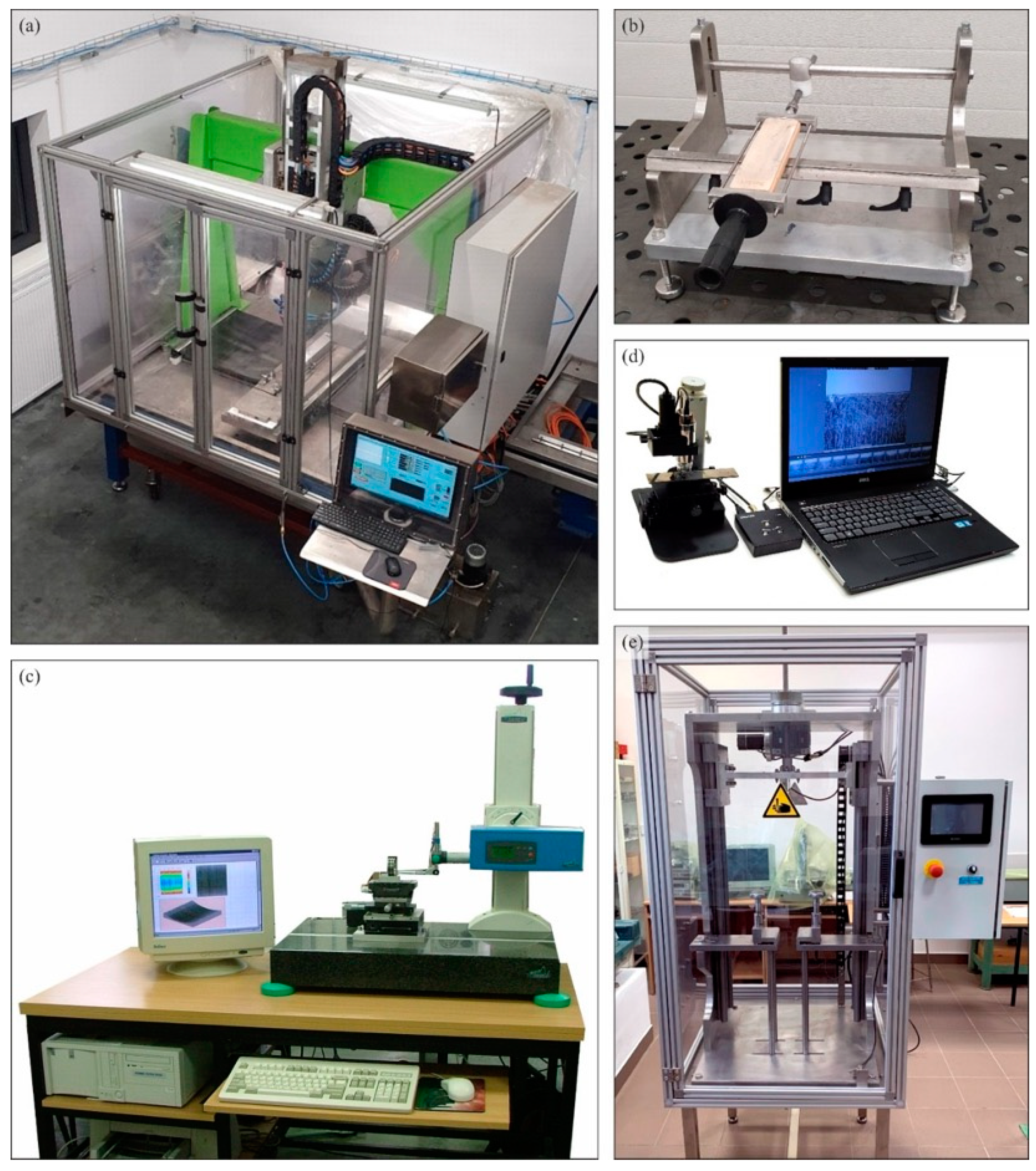
| Test stand | Specialized five-axis CNC grinding machine for shaping knife blades with low rigidity | |
| Workpiece | Planar knives designed for the process of skinning flat fish made of high-carbon martensitic X39Cr13 stainless steel (Kuno Wasser GmbH, Solingen, Germany for Steen F.P.M. International, Kalmthout, Belgium) | |
| Grinding wheel | 5A1 35 × 25 × 10/22 × 15 B181 V240 SV (INTER-DIAMENT, Grodzisk Mazowiecki, Poland) | |
| Dressing parameters of the grinding wheel | Dresser: M1039/D 1.00 ct (Dialeks, Pruszków, Poland) Rotational speed of grinding wheel in dressing: nsd = 32,000 rpm Feed rate during dressing: vfd = 0.00165 m/s Dressing allowance: ad = 0.03 mm Number of dressing passes: id = 2 | |
| Grinding parameters | Constant input quantities | Variable input quantities |
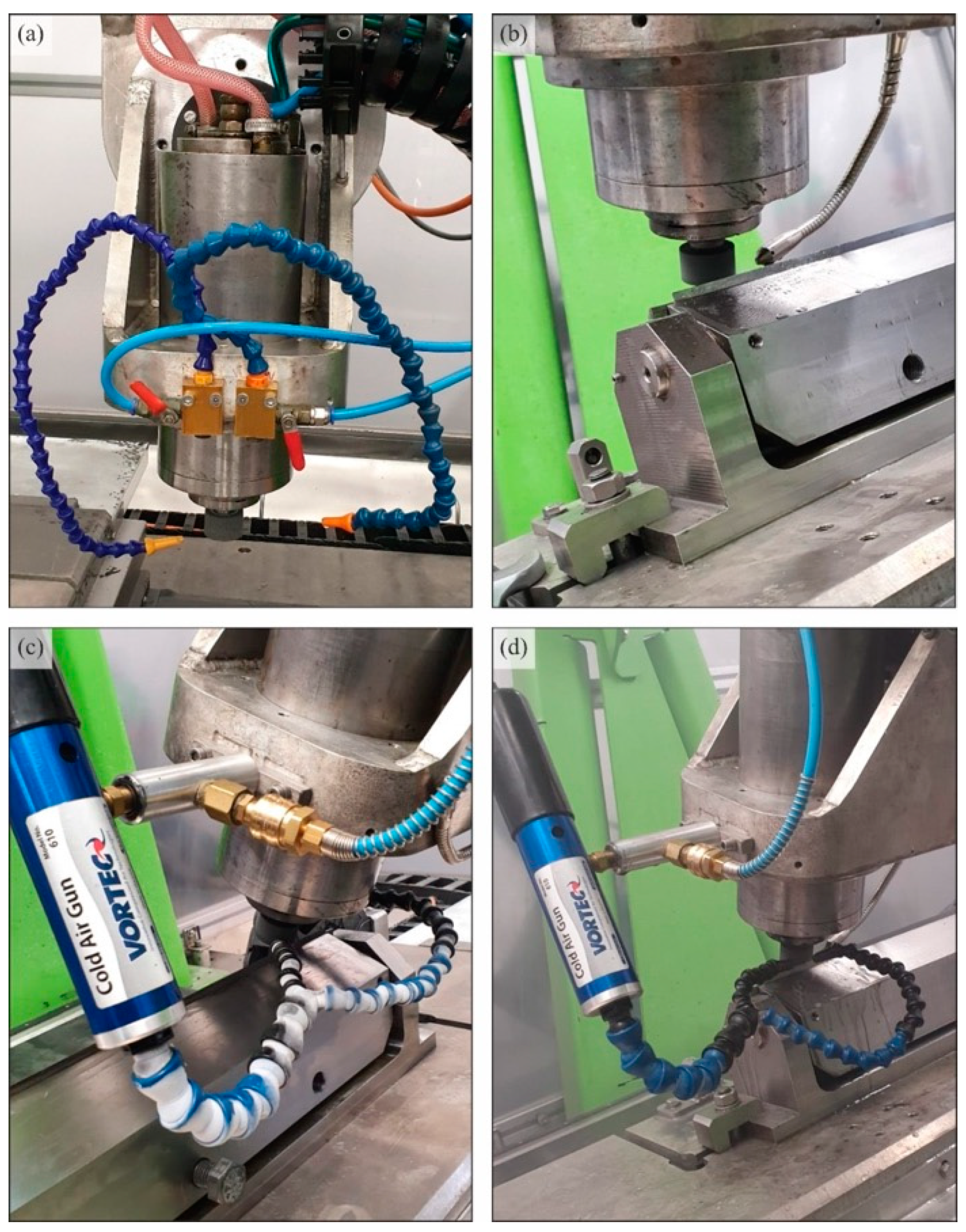
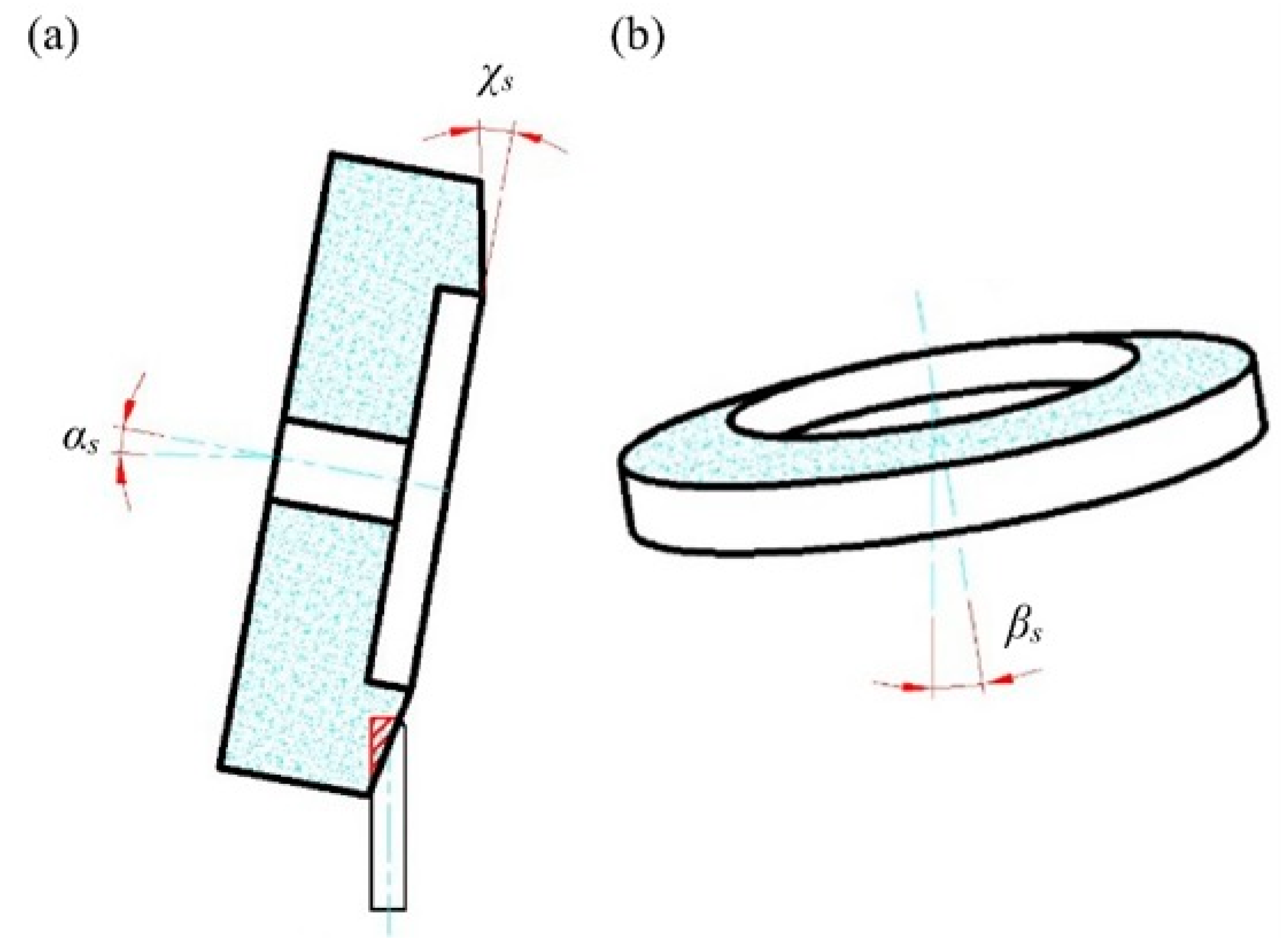
| Rotational speed of grinding wheel: ns = 32,000 rpm Allowance for rough passage: ae rough = 0.10 mm Longitudinal feed velocity of the grinding wheel: vf = 100 mm/min Number of roughing passes for both phases of the blade: 1 Allowance for sparking-out passage: ae sparking-out = 0.02 mm Number of sparking-out passes for both phases of the blade: 1 Direction of rotation of the grinding wheel: right—in the direction of the axis of symmetry of the knife (to the blade) Grinding kinematics: grinding with the conical surface of the grinding wheel Angular positioning of the grinding wheel in the grinding process: αs = 85°, βs = 5°, χs = 20° | Conditions for delivering cooling and lubricating agents to the grinding zone: flooding method (WET), minimum quantity lubrication MQL, cooling using cooled compressed air generated by CAG nozzle and the hybrid method combining MQL and CAG nozzle (MQL + CAG) | |
| Cooling and lubrication conditions of the grinding zone | Flooding (WET) cooling using a low-pressure circular nozzle with expenditure Q = 1.75 dm3/min. Coolant: 5% water-oil emulsion of Cimtech® M26 oil by CIMCOOL® Fluid Technology forming part of Milacron LLC (Cincinnati, OH, USA) | |
| Minimum quantity lubrication using ZMIN-MS nozzle by Sommer-Technik GmbH (Straubenhardt, Germany) with expenditure QMQL = 1100 mL/h. Air pressure feeding the nozzle: 0.8 MPa. Coolant: air-oil aerosol (Cimtech® MQL oil by CIMCOOL® Fluid Technology forming part of Milacron LLC, Cincinnati, OH, USA) | ||
| Cooling using cooled compressed air generated by a Vortec 610 CAG nozzle by ITW Vortec and Paxton Products (Cincinnati, OH, USA) with expenditure QCAG = 49.8 dm3/min. Air pressure feeding the nozzle: 0.6 MPa. Coolant: cooled compressed air | ||
| Designation of the Blade Selected for Analysis | Surface Texture Parameters | |||||||
|---|---|---|---|---|---|---|---|---|
| Amplitude | Area and Volume | Spatial | Hybrid | Functional | ||||
| Sa, µm | St, µm | Smvr, mm3/mm2 | Sds, mm−2 | Str | Sdq, µm/µm | Sdr, % | Sbi | |
| WET (repetition 1) | 0.1180 | 2.150 | 0.001480 | 6344 | 0.1430 | 0.0222 | 0.1360 | 0.1050 |
| WET (repetition 2) | 0.1010 | 1.300 | 0.000760 | 6155 | 0.4990 | 0.0518 | 0.1340 | 0.2350 |
| WET (repetition 3) | 0.1130 | 2.020 | 0.001110 | 5964 | 0.1870 | 0.0522 | 0.1290 | 0.1470 |
| MQL (repetition 1) | 0.1560 | 2.320 | 0.001420 | 5297 | 0.2550 | 0.0436 | 0.0947 | 0.2030 |
| MQL (repetition 2) | 0.1250 | 1.920 | 0.001260 | 5667 | 0.3910 | 0.0484 | 0.1170 | 0.1830 |
| MQL (repetition 3) | 0.1470 | 2.420 | 0.001470 | 5264 | 0.4090 | 0.0470 | 0.1100 | 0.1860 |
| CAG (repetition 1) | 0.0791 | 2.210 | 0.001210 | 6255 | 0.1860 | 0.0305 | 0.0464 | 0.1060 |
| CAG (repetition 2) | 0.1710 | 2.650 | 0.001700 | 5655 | 0.1860 | 0.0440 | 0.0966 | 0.1690 |
| CAG (repetition 3) | 0.0636 | 1.100 | 0.000625 | 6225 | 0.1860 | 0.0321 | 0.0514 | 0.1690 |
| MQL + CAG (repetition 1) | 0.2460 | 4.060 | 0.002290 | 4511 | 0.4290 | 0.0664 | 0.2200 | 0.1980 |
| MQL + CAG (repetition 2) | 0.206 | 3.140 | 0.001590 | 4613 | 0.1900 | 0.0585 | 0.1710 | 0.2540 |
| MQL + CAG (repetition 3) | 0.179 | 2.620 | 0.001550 | 5143 | 0.1930 | 0.0516 | 0.1330 | 0.2210 |
Publisher’s Note: MDPI stays neutral with regard to jurisdictional claims in published maps and institutional affiliations. |
© 2022 by the authors. Licensee MDPI, Basel, Switzerland. This article is an open access article distributed under the terms and conditions of the Creative Commons Attribution (CC BY) license (https://creativecommons.org/licenses/by/4.0/).
Share and Cite
Zieliński, B.; Nadolny, K.; Zawadka, W.; Chaciński, T.; Stachurski, W.; Batalha, G.F. Effect of Pro-Ecological Cooling and Lubrication Methods on the Sharpening Process of Planar Blades Used in Food Processing. Materials 2022, 15, 7842. https://doi.org/10.3390/ma15217842
Zieliński B, Nadolny K, Zawadka W, Chaciński T, Stachurski W, Batalha GF. Effect of Pro-Ecological Cooling and Lubrication Methods on the Sharpening Process of Planar Blades Used in Food Processing. Materials. 2022; 15(21):7842. https://doi.org/10.3390/ma15217842
Chicago/Turabian StyleZieliński, Bartosz, Krzysztof Nadolny, Wojciech Zawadka, Tomasz Chaciński, Wojciech Stachurski, and Gilmar Ferreira Batalha. 2022. "Effect of Pro-Ecological Cooling and Lubrication Methods on the Sharpening Process of Planar Blades Used in Food Processing" Materials 15, no. 21: 7842. https://doi.org/10.3390/ma15217842