
Experimental Investigation of Suitable Cutting Conditions of Dry Drilling into High-Strength Structural Steel

 , , ,
, , ,
Abstract
:1. Introduction
1.1. Specifics of Dry Machining Technology
1.2. Determining the Direction of Research
2. Materials and Methods
2.1. Materials
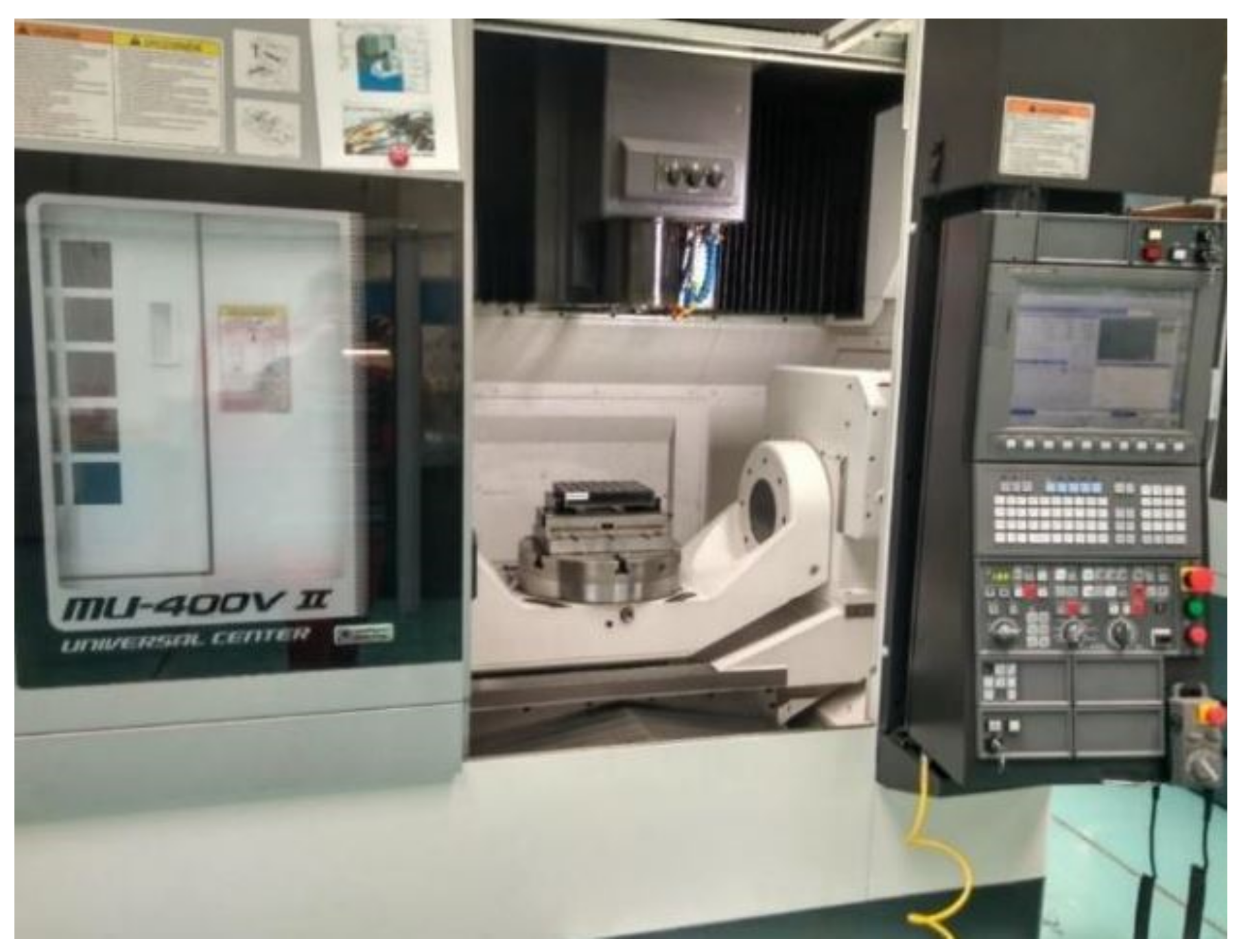
2.2. Equipment
2.3. Methods
3. Results and Discussion
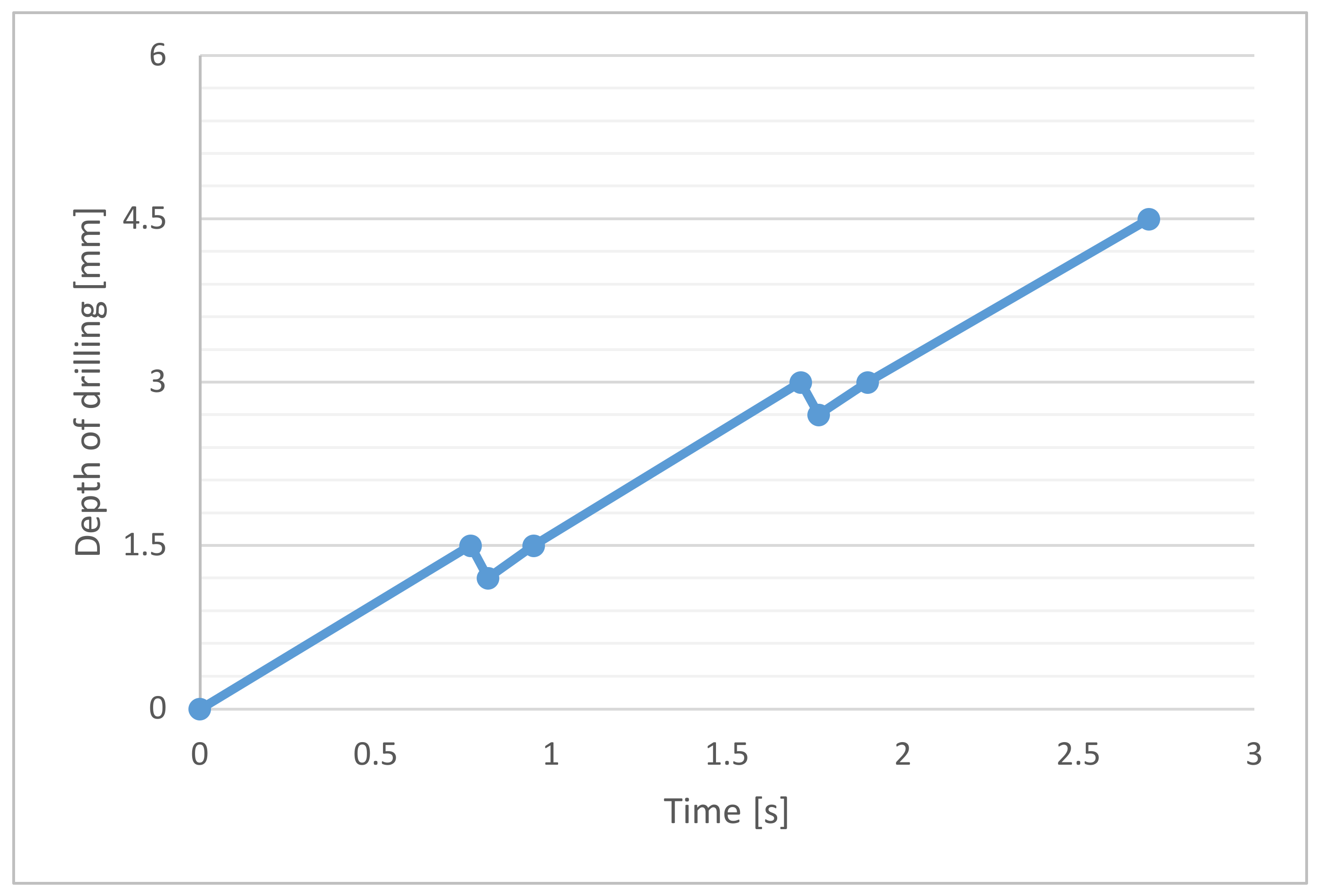
3.1. Drilling Torque
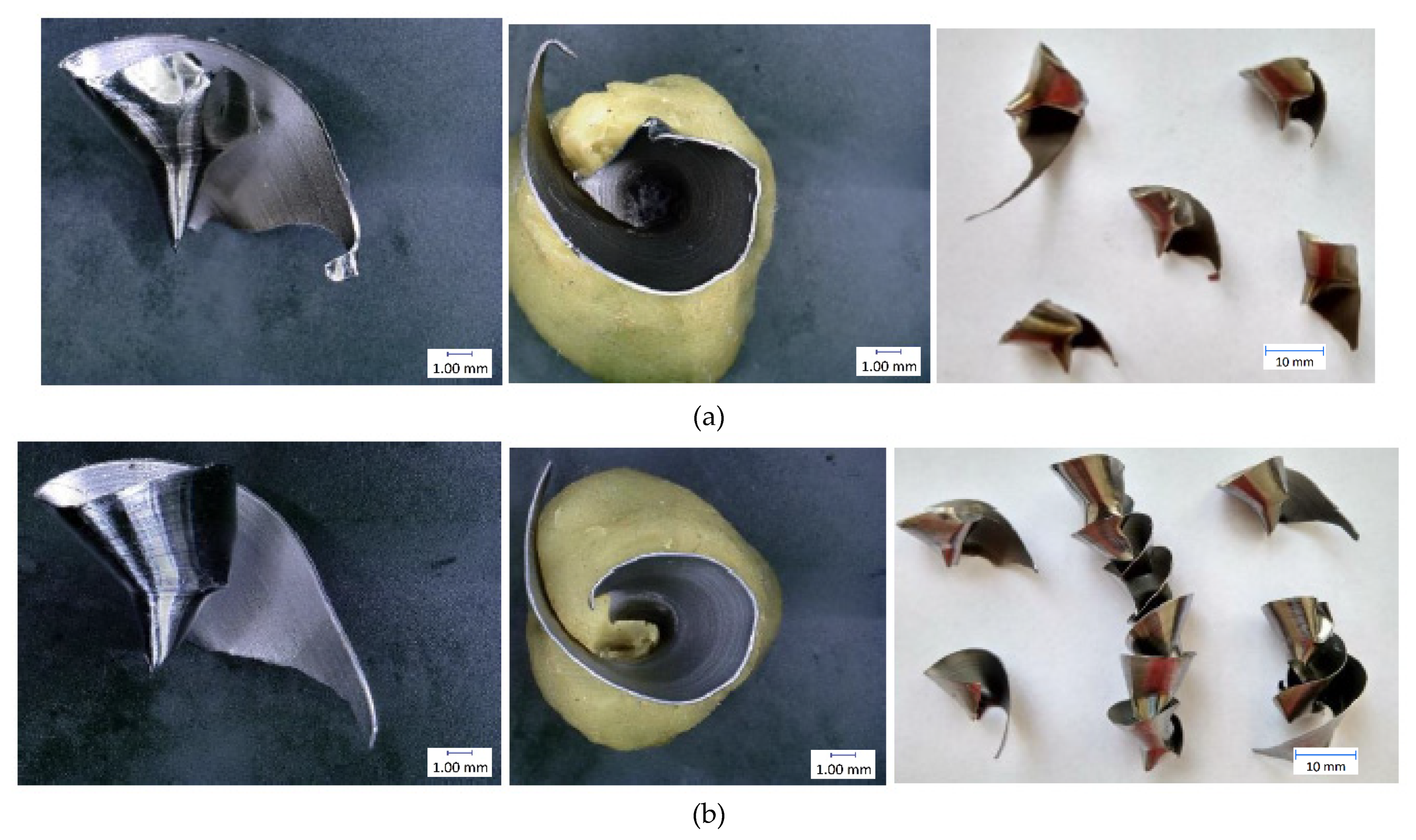
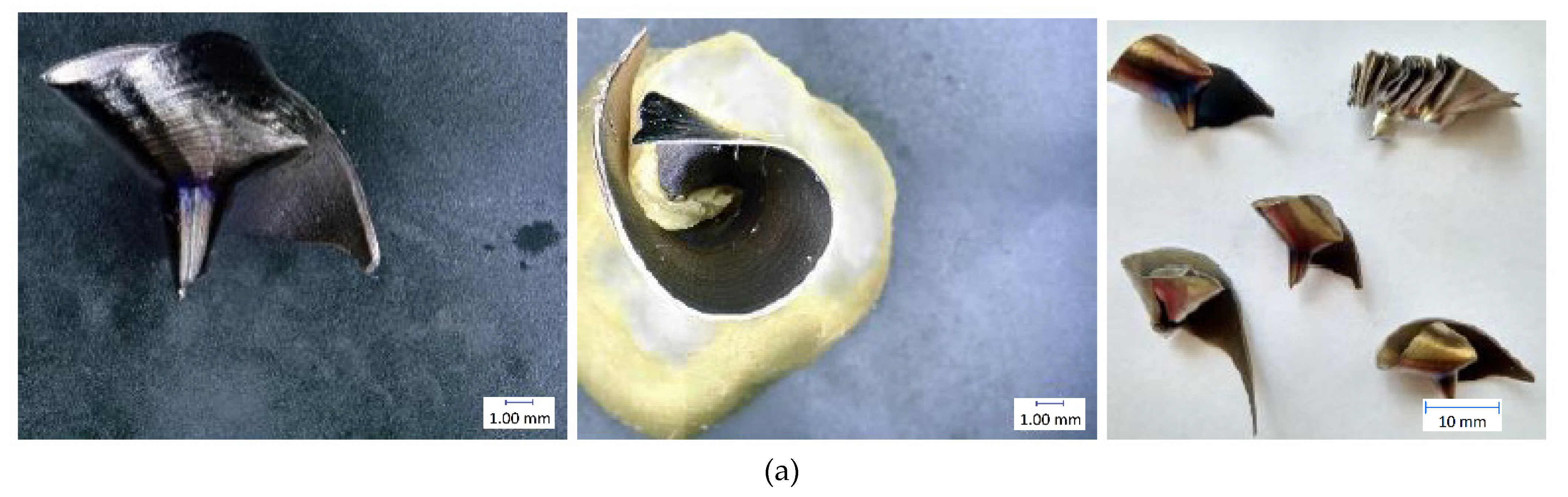
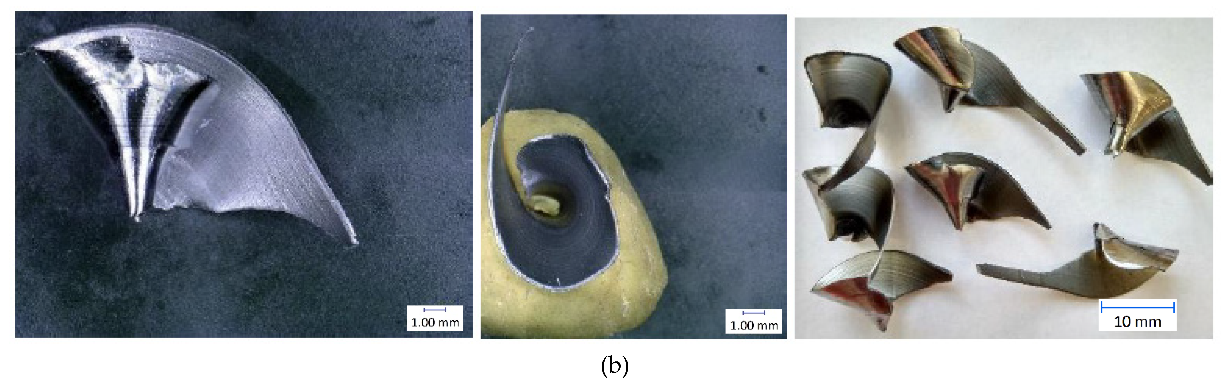
3.2. Chip Formation
Chip Morphology
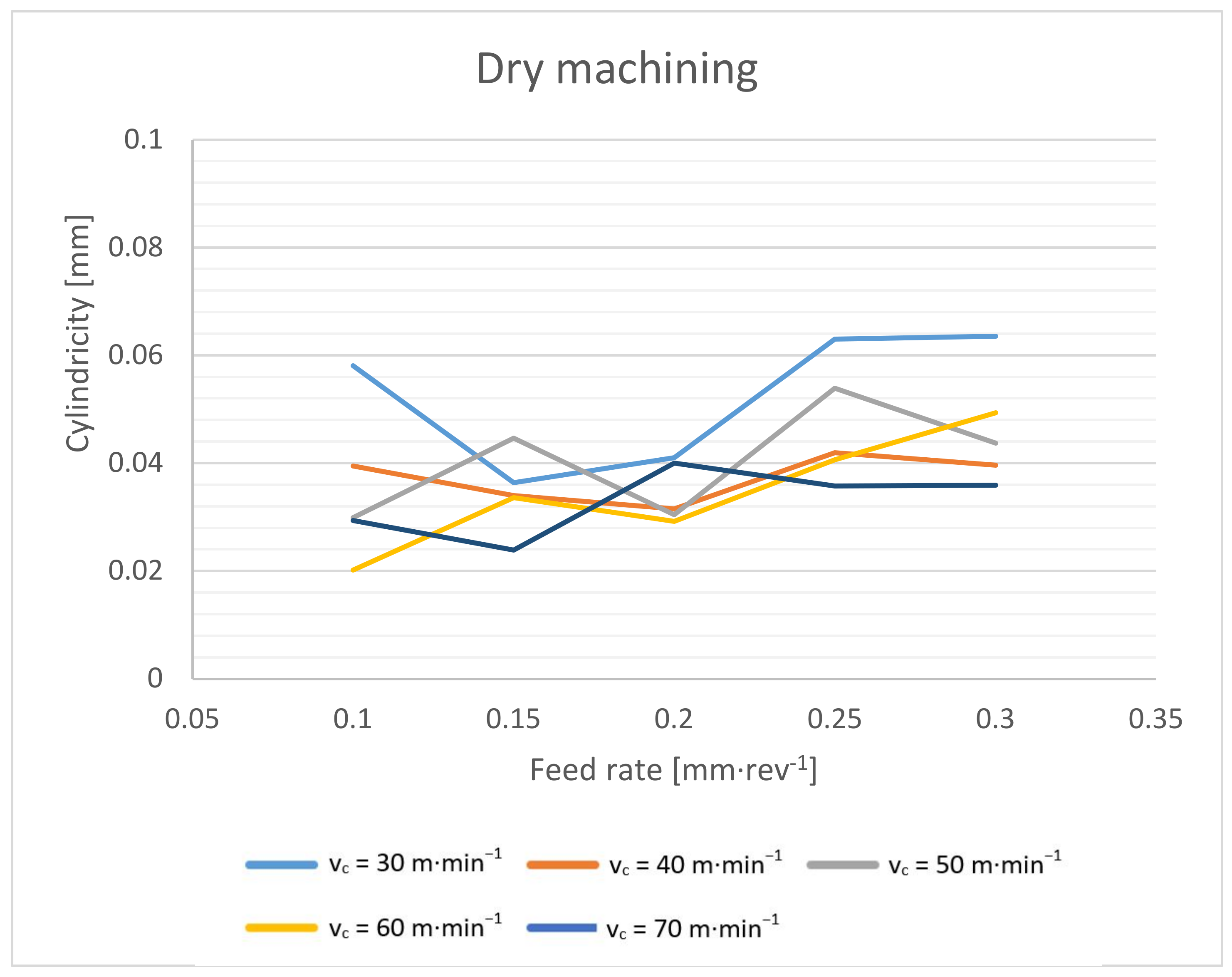
3.3. Dimensions
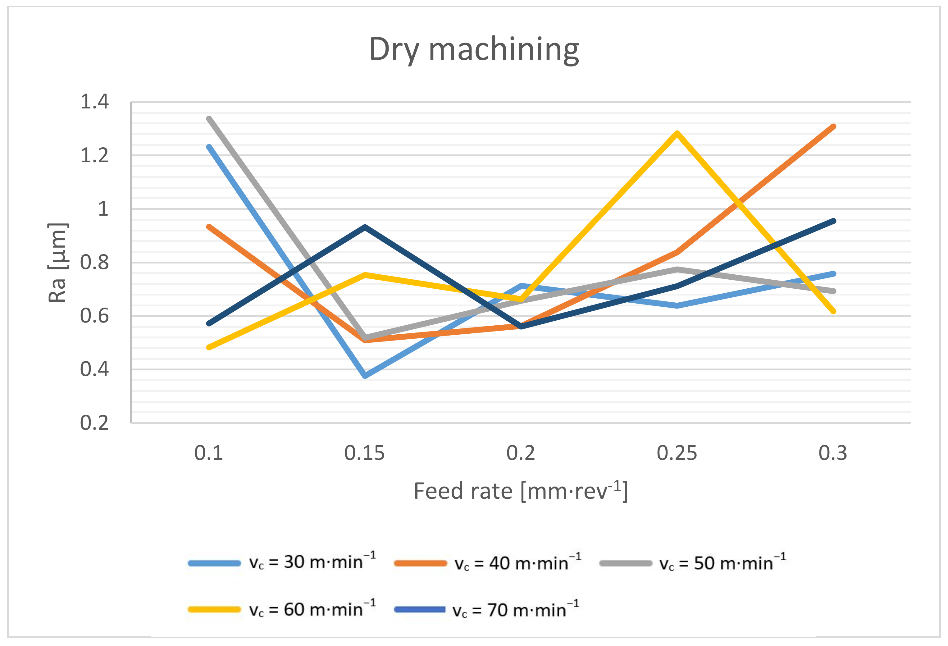
3.4. Surface Roughness
4. Conclusions
- A significant decrease in the spindle torque occurs when the cutting speed is increased to 50 m·min−1. From this value, the torque is basically constant. When drilling without cutting fluid, the torque is only about 4–7% higher compared to wet machining.
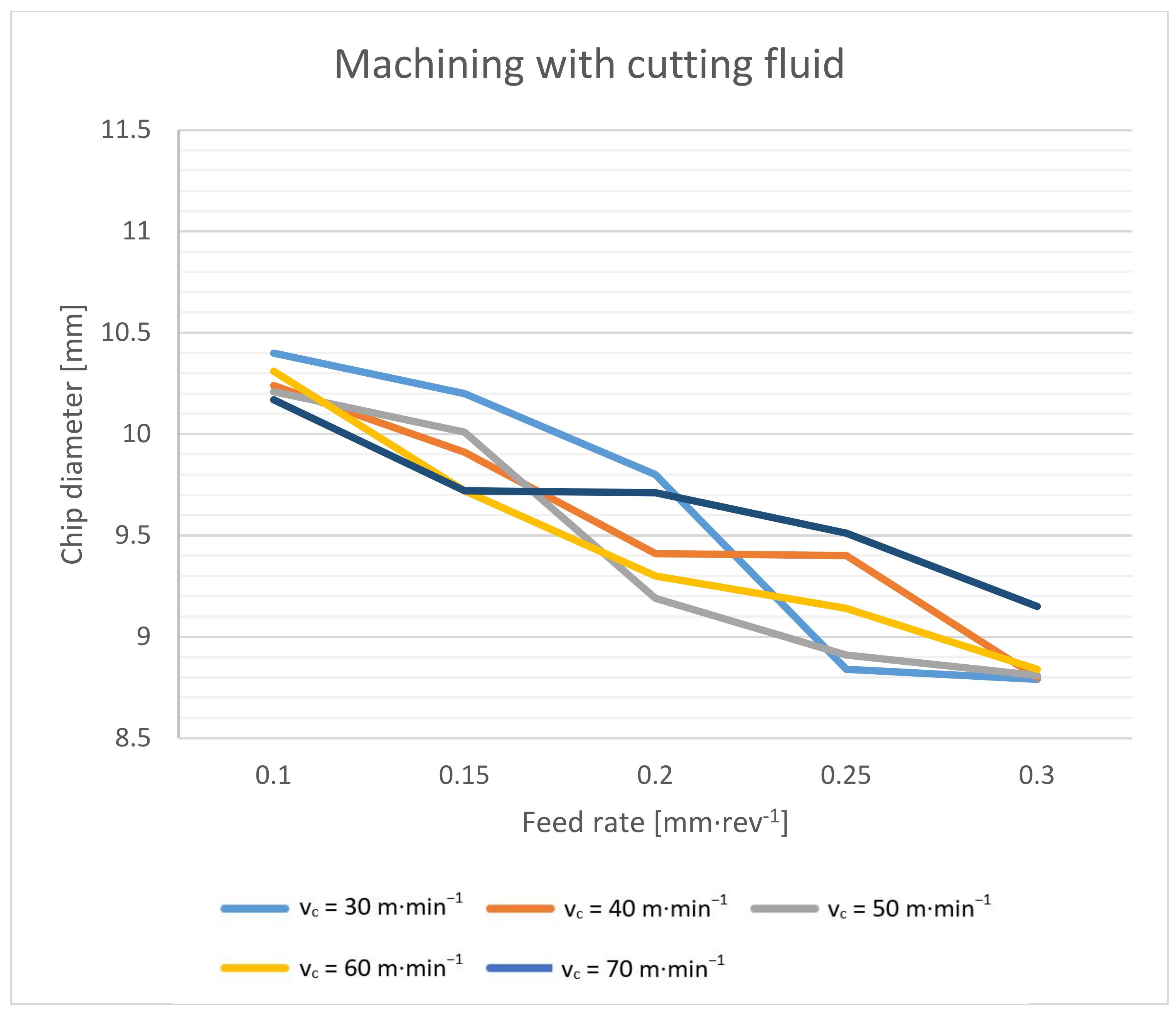
- The chip thickness ratio decreases significantly with an increasing feed rate. Additionally, the maximum diameter of the formed chips decreases with an increasing feed rate. The effect of the cutting speed on these values was not proven in this experiment. When evaluating the achieved results and the macroscopic morphology of the chips, the suitable cutting conditions for the dry drilling of the Weldox 960 material with the tool of the mentioned concept were determined. The cutting speed of around 50 m·min−1 reaches a suitable compromise between cutting forces, elemental chip formation and process stability. The feed rate of about 0.25 mm·rev−1 then reaches a suitable compromise in terms of splitting and chip size, chip thickness ratio, cutting forces and the quality of the drilled holes.
- From the point of view of the dimensional accuracy, it must be taken into account that the drilled holes are approximately 0.03 mm larger during dry machining. An interesting result was achieved. The cylindricity of the wet machined holes is slightly larger compared to that achieved with the dry-machined holes. The cylindricity increases with an increasing feed rate and a decreasing cutting speed, which is related to the magnitude of the torque and cutting forces. However, the cylindricity increases more when machining with cutting fluid. The surface roughness depends on the cutting conditions when machining with cutting fluid, and the resulting surface roughness can be achieved repeatedly. In dry machining, the surface roughness is primarily formed by the outgoing chips, and the resulting surface roughness is usually in a certain range (Ra 0.5–1.2 µm), but it is not possible to achieve it repeatedly.
Author Contributions
Funding
Institutional Review Board Statement
Informed Consent Statement
Data Availability Statement
Conflicts of Interest
References
- Goindi, G.S.; Sarkar, P. Dry machining: A step towards sustainable machining—Challenges and future directions. J. Clean. Prod. 2017, 165, 1557–1571. [Google Scholar] [CrossRef]
- Gajrani, K.K.; Ram, D.; Sankar, M.R.; Dixit, U.S.; Suvin, P.S.; Kailas, S.V. Machining of hardened AISI H-13 steel using minimum quantity eco-friendly cutting fluid. Int. J. Addit. Subtractive Mater. Manuf. 2017, 1, 240–256. [Google Scholar] [CrossRef]
- Sreejith, P.S.; Ngoi, B.K.A. Dry machining: Machining of the future. J. Mater. Process. Technol. 2000, 101, 287–291. [Google Scholar] [CrossRef]
- Kumar, S.; Singh, D.; Kalsi, N.S. Analysis of Surface Roughness during Machining of Hardened AISI 4340 Steel using Minimum Quantity lubrication. Mater. Today Proc. 2017, 4, 3627–3635. [Google Scholar] [CrossRef]
- Cantero, J.L.; Tardío, M.M.; Canteli, J.A.; Marcos, M.; Miguélez, M.H. Dry drilling of alloy Ti–6Al–4V. Int. J. Mach. Tools Manuf. 2005, 45, 1246–1255. [Google Scholar] [CrossRef] [Green Version]
- Feng, S.; Hattori, M. Cost and process information modeling for dry machining. In Proceedings of the International Workshop on Environment and Manufacturing, National Institute of Standards and Technology, Gaithersburg, MD, USA, 22 February 2001. [Google Scholar]
- Biró, I.; Czampa, M.; Szalay, T. Experimental Model for the Main Cutting Force in Face Milling of a High Strength Structural Steel. Period. Polytech. Mech. Eng. 2015, 59, 16–22. [Google Scholar] [CrossRef]
- Qiang, X.; Jiang, X.; Bijlaard, F.S.K.; Kolstein, H.; Erkens, G.; Wenke, R.; Cselle, T.; Schwenck, M. Mechanical properties and design recommendations of very high strength steel S960 in fire. Eng. Struct. 2016, 112, 60–70. [Google Scholar] [CrossRef]
- Cadoni, E.; Forni, D.; Bijlaard, F.S.K.; Kolstein, H.; Erkens, G.; Wenke, R.; Cselle, T.; Schwenck, M. Mechanical behaviour of a very-high strength steel (S960QL) under extreme conditions of high strain rates and elevated temperatures. Fire Saf. J. 2019, 109, 60–70. [Google Scholar] [CrossRef]
- Haan, D.M.; Batzer, S.A.; Olson, W.W.; Sutherland, J.W. An experimental study of cutting fluid effects in drilling. J. Mater. Process. Technol. 1997, 71, 305–313. [Google Scholar] [CrossRef]
- Surendran, V. A Study of Hole Quality in Drilling. Master’s Thesis, University of Illinois at Urbana-Champaign, Champaign, IL, USA, 1998. [Google Scholar]
- Bono, M.; Ni, J. The effects of thermal distortions on the diameter and cylindricity of dry drilled holes. Int. J. Mach. Tools Manuf. 2001, 41, 2261–2270. [Google Scholar] [CrossRef]
- Merzouki, J.; Poulachon, G.; Rossi, F.; Ayed, Y.; Abrivard, G. Method of Hole Shrinkage Radial Forces Measurement in Ti6Al4V Drilling. Procedia CIRP 2017, 58, 629–634. [Google Scholar] [CrossRef]
- Subramanian, K.; Cook, N.H. Sensing of Drill Wear and Prediction of Drill Life. J. Eng. Ind. 1977, 99, 295–301. [Google Scholar] [CrossRef] [Green Version]
- Kalidas, S.; DeVor, R.E.; Kapoor, S.G. Experimental investigation of the effect of drill coatings on hole quality under dry and wet drilling conditions. Surf. Coat. Technol. 2001, 148, 117–128. [Google Scholar] [CrossRef]
- Pirtini, M.; Lazoglu, I. Forces and hole quality in drilling. Int. J. Mach. Tools Manuf. 2005, 45, 1271–1281. [Google Scholar] [CrossRef]
- Kilickap, E.; Huseyinoglu, M.; Yardimeden, A. Optimization of drilling parameters on surface roughness in drilling of AISI 1045 using response surface methodology and genetic algorithm. Int. J. Adv. Manuf. Technol. 2011, 52, 79–88. [Google Scholar] [CrossRef]
- Balaji, M.; Venkata Rao, K.; Mohan Rao, N.; Murthy, B.S.N. Optimization of drilling parameters for drilling of TI-6Al-4V based on surface roughness, flank wear and drill vibration. Measurement 2018, 114, 332–339. [Google Scholar] [CrossRef]
- Jantunen, E. Automated on-line diagnosis of cutting tool condition. Int. J. Flex. Autom. Integr. Manuf. 1996, 4, 273–287. [Google Scholar]
- Heinemann, R.; Hinduja, S.; Barrow, G.; Petuelli, G. Effect of MQL on the tool life of small twist drills in deep-hole drilling. Int. J. Mach. Tools Manuf. 2006, 46, 1–6. [Google Scholar] [CrossRef]
- Bhowmick, S.; Lukitsch, M.J.; Alpas, A.T.; Petuelli, G. Dry and minimum quantity lubrication drilling of cast magnesium alloy (AM60). Int. J. Mach. Tools Manuf. 2010, 50, 444–457. [Google Scholar] [CrossRef]
- Paul, A.; Kapoor, S.G.; DeVor, R.E. A Chisel Edge Model for Arbitrary Drill Point Geometry. J. Manuf. Sci. Eng. 2005, 127, 23–32. [Google Scholar] [CrossRef]
- Feng, K. Analysis And Modeling of Chip Ejection in Deep Hole Drilling Processes. Ph.D. Thesis, University of Michigan Michigan, Ann Arbor, MI, USA, 2003. [Google Scholar]
- Weldox 960 Data Sheet. Available online: http://www.dimonthdx.cz/soubory_texty/1_10.pdf (accessed on 12 May 2021).
- Kim, S.-I.; Kim, M.-H. Evaluation of cutting characterization in plasma cutting of thick steel ship plates. Int. J. Precis. Eng. Manuf. 2013, 14, 1571–1575. [Google Scholar] [CrossRef]
- Kyncl, J.; Kellner, T.; Kyncl, M.; Pelikán, L. Weldox 960 Dry Machining. In Technological Forum 2017 Book of Proceedings; Jan Kudláček: Jaroměř, Czech Republic, 2017; pp. 60–65. ISBN 978-80-87583-22-7. [Google Scholar]
- Pelikán, L.; Kellner, T.; Kyncl, M. Dry drilling into weldments from hard-to-machine material. In Studentská Tvůrčí Činnost; Czech Technical University: Prague, Czech Republic, 2018; ISBN 978-80-01-06421-4. [Google Scholar]
- Tönshoff, K.; Mohlfeld, A.; Leyendecker, T.; Fuß, H.G.; Erkens, G.; Wenke, R.; Cselle, T.; Schwenck, M. Wear mechanisms of (Ti1 − x,Alx)N coatings in dry drilling. Surf. Coat. Technol. 1997, 94–95, 603–609. [Google Scholar] [CrossRef]
- Derflinger, V.; Brändle, H.; Zimmermann, H.; Fuß, H.G.; Erkens, G.; Wenke, R.; Cselle, T.; Schwenck, M. New hard/lubricant coating for dry machining. Surf. Coat. Technol. 1999, 113, 286–292. [Google Scholar] [CrossRef]
- Jantunen, E.; Ram, D.; Sankar, M.R.; Dixit, U.S.; Suvin, P.S.; Kailas, S.V. A summary of methods applied to tool condition monitoring in drilling. Int. J. Mach. Tools Manuf. 2002, 42, 997–1010. [Google Scholar] [CrossRef]
- Xiaoli, L.; Ram, D.; Sankar, M.R.; Dixit, U.S.; Suvin, P.S.; Kailas, S.V. On-line detection of the breakage of small diameter drills using current signature wavelet transform. Int. J. Mach. Tools Manuf. 1999, 39, 157–164. [Google Scholar] [CrossRef] [Green Version]
- Ke, F.; Ni, J.; Stephenson, D.A. Continuous chip formation in drilling. Int. J. Mach. Tools Manuf. 2005, 45, 1652–1658. [Google Scholar] [CrossRef]
- Paul, A.; Kapoor, S.G.; DeVor, R.E. Chisel edge and cutting lip shape optimization for improved twist drill point design. Int. J. Mach. Tools Manuf. 2005, 45, 421–431. [Google Scholar] [CrossRef]
- Antic, A.; Kozak, D.; Kosec, B.; Simunovic, G.; Saric, T.; Kovacevic, D.; Cep, R. Influence of Tool Wear on the Mechanism of Chips Segmentation and Tool Vibration. Teh. Vjesn. Tech. Gaz. 2013, 20, 105–112. [Google Scholar]
- Kolesnyk, V.; Peterka, J.; Kuruc, M.; Šimna, V.; Moravčíková, J.; Vopát, T.; Lisovenko, D. Experimental Study of Drilling Temperature, Geometrical Errors and Thermal Expansion of Drill on Hole Accuracy When Drilling CFRP/Ti Alloy Stacks. Materials 2020, 13, 3232. [Google Scholar] [CrossRef]
- Habib, N.; Sharif, A.; Hussain, A.; Aamir, M.; Giasin, K.; Pimenov, D.Y.; Ali, U. Analysis of Hole Quality and Chips Formation in the Dry Drilling Process of Al7075-T6. Metals 2021, 11, 891. [Google Scholar] [CrossRef]
- Çelik, Y.H. Investigating the Effects of Cutting Parameters on the Hole quality in Drilling the Ti-6Al-4V alloy. Mater. Technol. 2014, 48, 653–659. [Google Scholar]


| C (max %) | Si (max %) | Mn (max %) | P (max %) | S (max %) | Cr (max %) | Cu (max %) | Ni (max %) | Mo (max %) |
|---|---|---|---|---|---|---|---|---|
| 0.2 | 0.5 | 1.6 | 0.02 | 0.01 | 0.8 | 0.3 | 2.0 | 0.7 |
| Plate Thickness (mm) | Yield Strength Rp0.2 (min MPa) | Tensile Strength Rm (MPa) | Elongation A5 (min %) |
|---|---|---|---|
| 4–53 | 960 | 980–1150 | 12 |
| 53.1–100 | 850 | 900–1100 | 10 |
Publisher’s Note: MDPI stays neutral with regard to jurisdictional claims in published maps and institutional affiliations. |
© 2021 by the authors. Licensee MDPI, Basel, Switzerland. This article is an open access article distributed under the terms and conditions of the Creative Commons Attribution (CC BY) license (https://creativecommons.org/licenses/by/4.0/).
Share and Cite
Pelikán, L.; Slaný, M.; Beránek, L.; Andronov, V.; Nečas, M.; Čepová, L. Experimental Investigation of Suitable Cutting Conditions of Dry Drilling into High-Strength Structural Steel. Materials 2021, 14, 4381. https://doi.org/10.3390/ma14164381
Pelikán L, Slaný M, Beránek L, Andronov V, Nečas M, Čepová L. Experimental Investigation of Suitable Cutting Conditions of Dry Drilling into High-Strength Structural Steel. Materials. 2021; 14(16):4381. https://doi.org/10.3390/ma14164381
Chicago/Turabian StylePelikán, Lukáš, Michal Slaný, Libor Beránek, Vladislav Andronov, Martin Nečas, and Lenka Čepová. 2021. "Experimental Investigation of Suitable Cutting Conditions of Dry Drilling into High-Strength Structural Steel" Materials 14, no. 16: 4381. https://doi.org/10.3390/ma14164381