
A Multi-Scale Submodel Method for Fatigue Analysis of Braided Composite Structures


Abstract
:1. Introduction
2. Multi-Scale Fatigue Analysis Method Based on Sub-Model
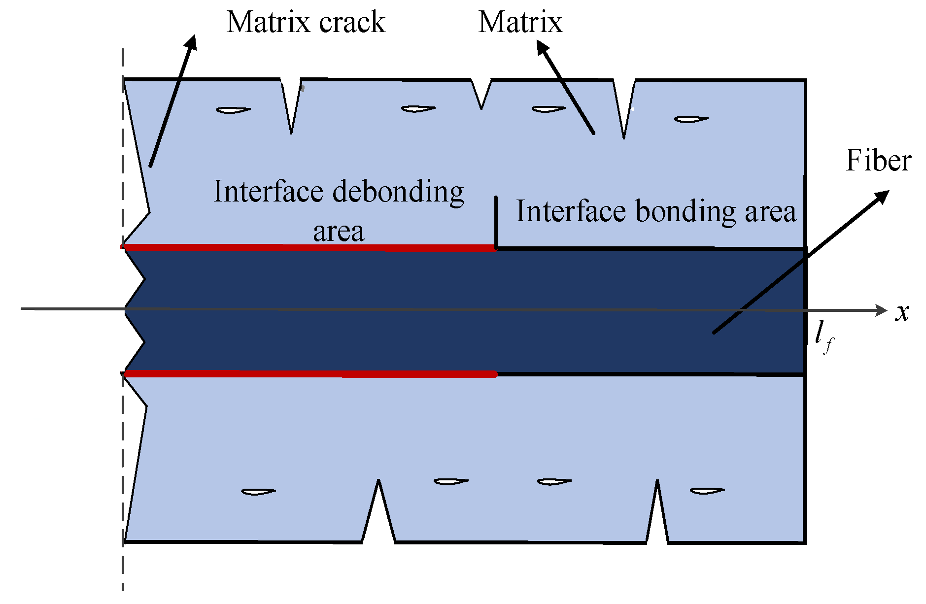
2.1. Fatigue Failure Criteria for CMCs
2.2. Fatigue Damage Accumulation Theory
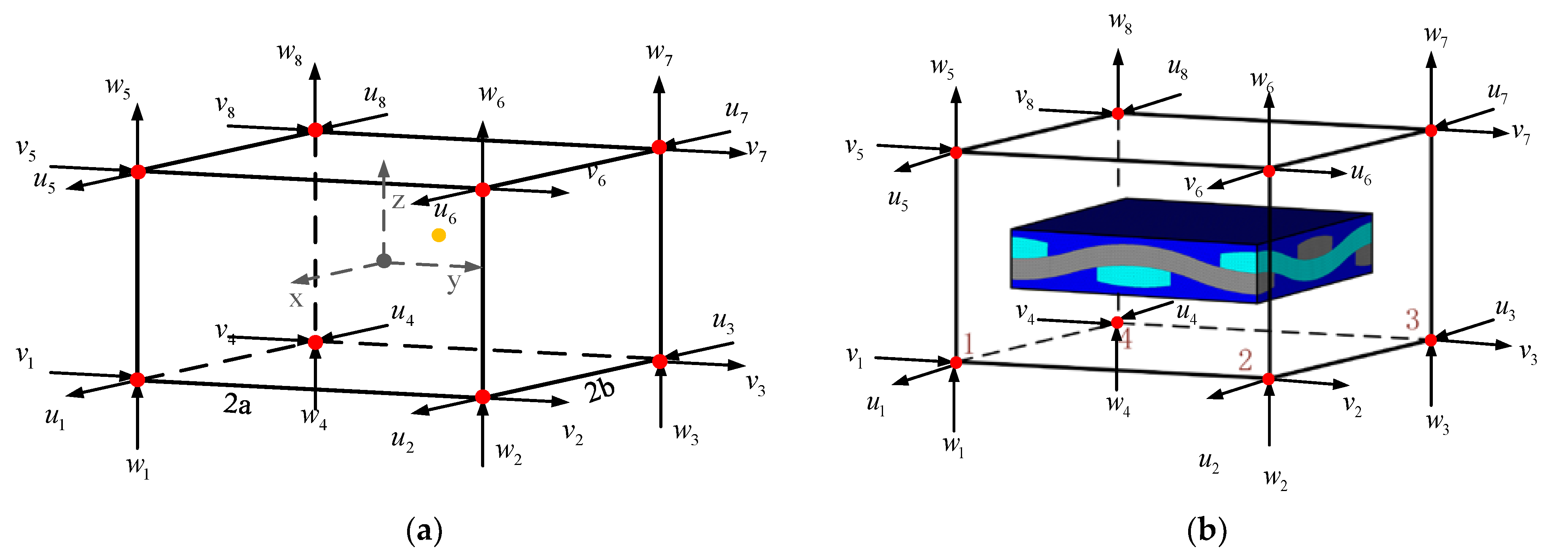
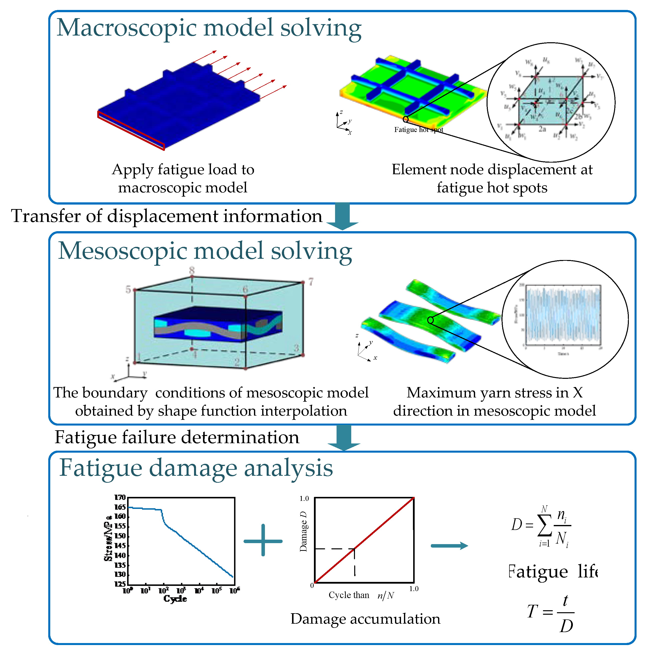
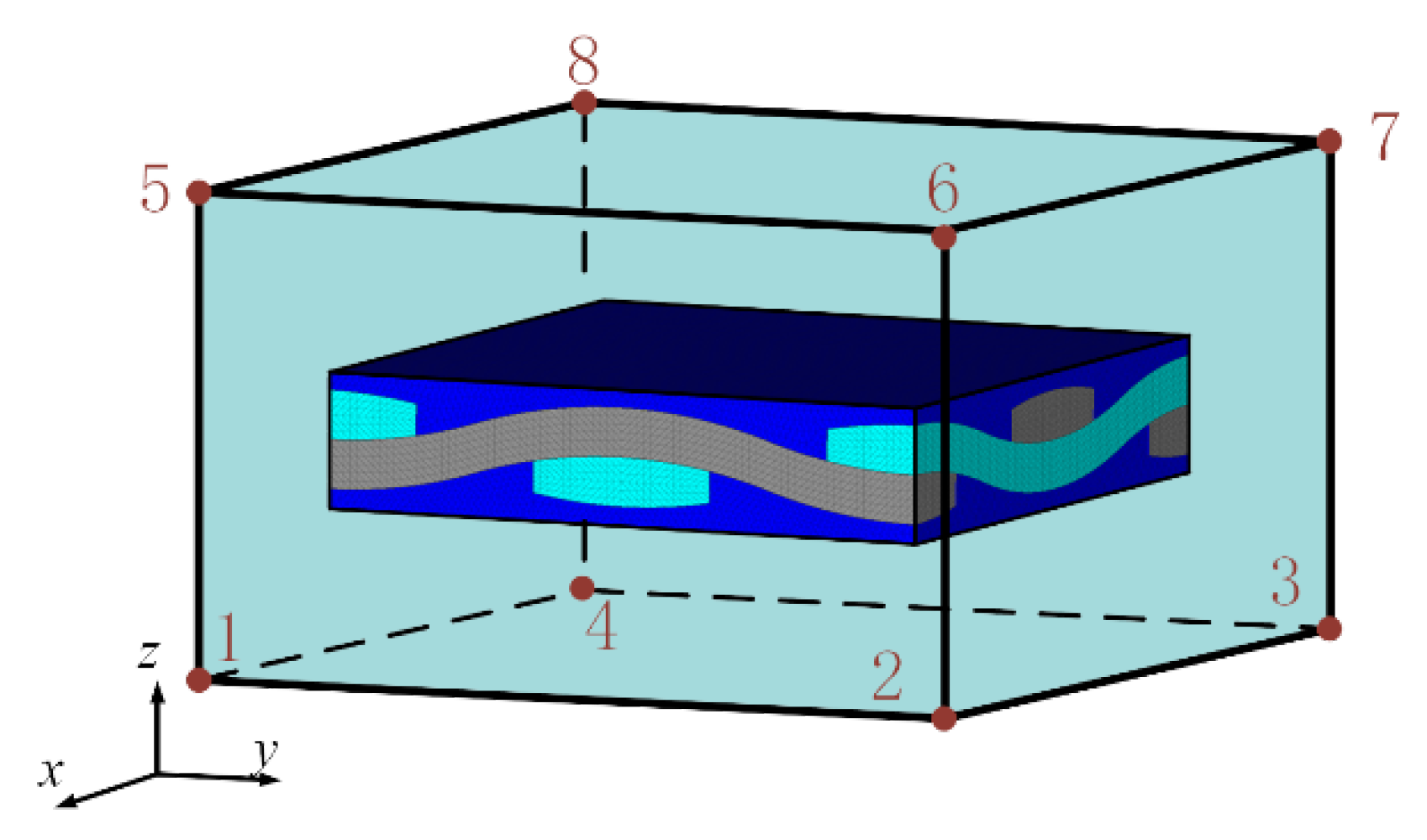
2.3. Sub-Model Method Based on Shape Function Interpolation
3. Case Study
3.1. Validation: Fatigue Life Calculation of 2D SiC/SiC Composites
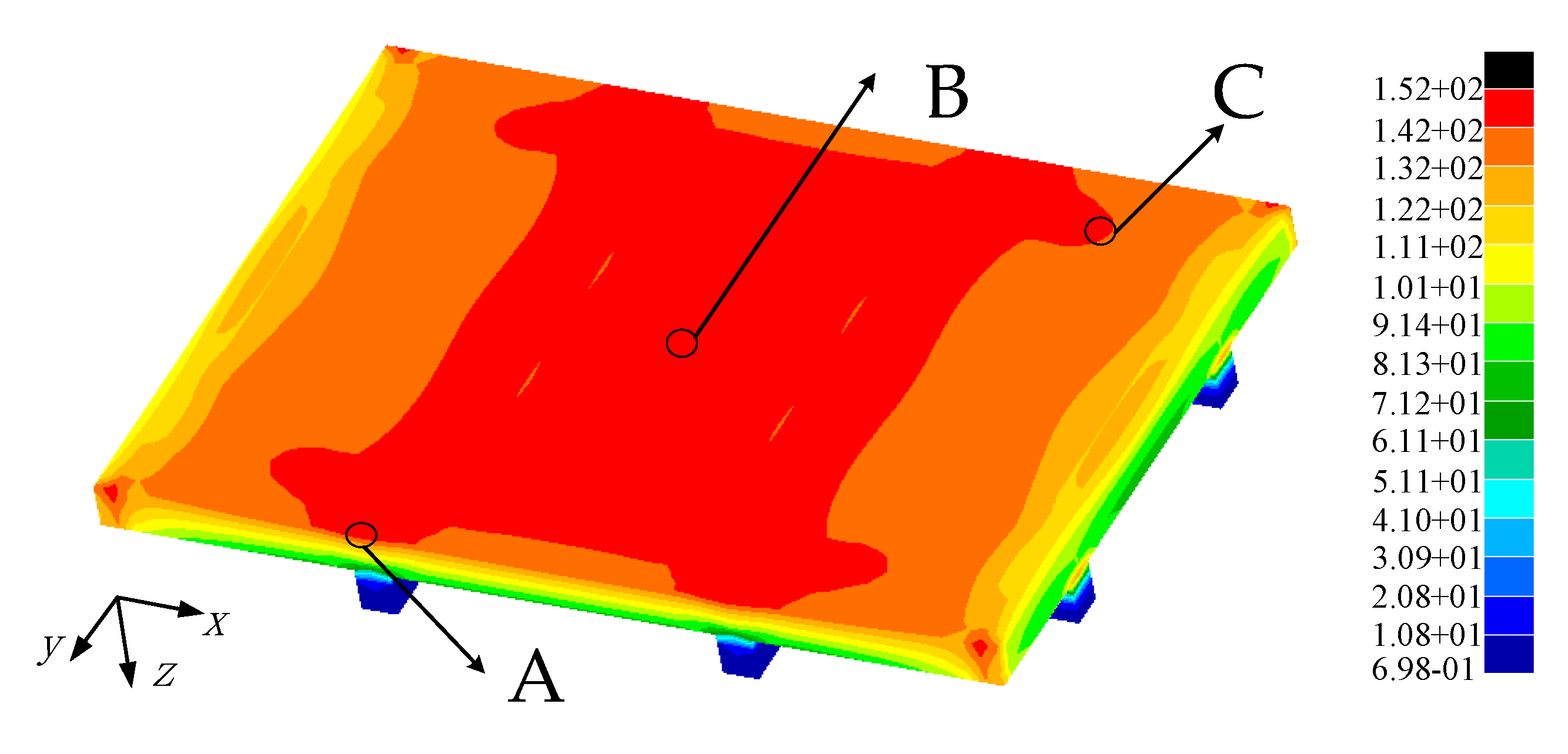
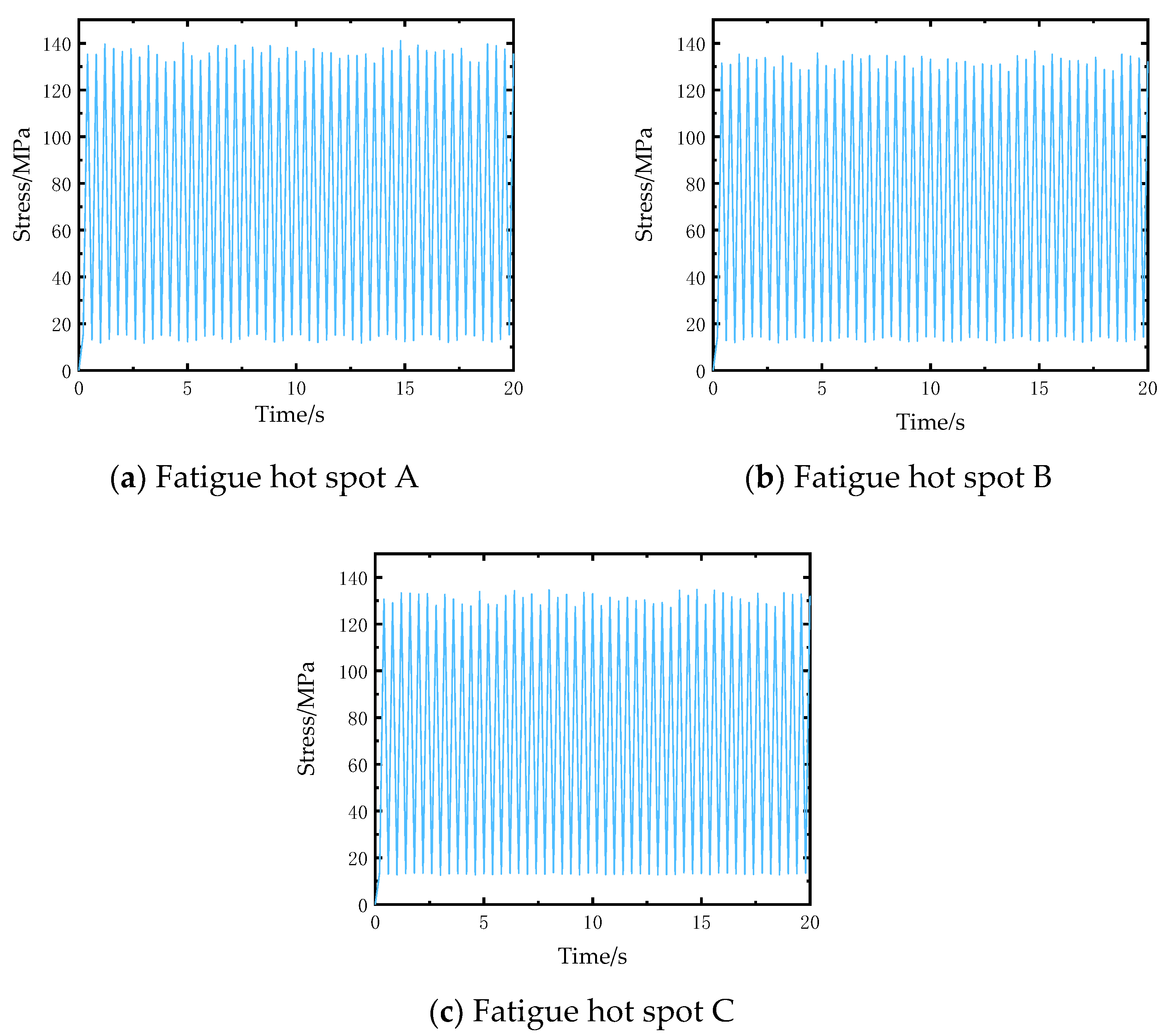
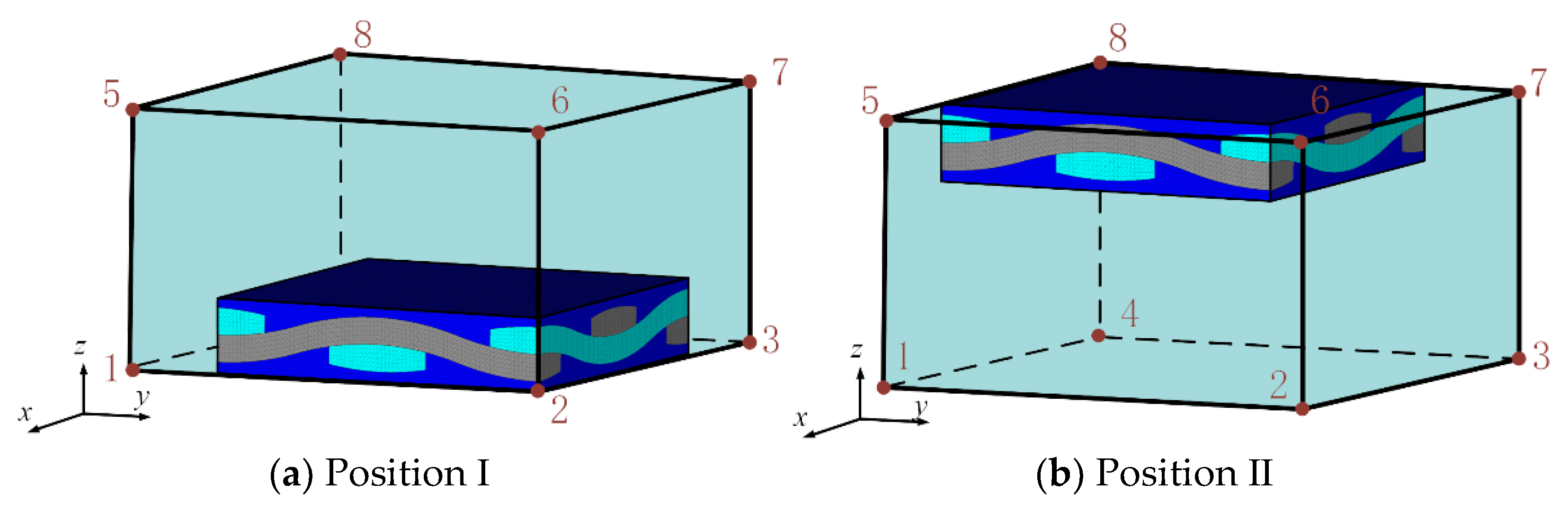
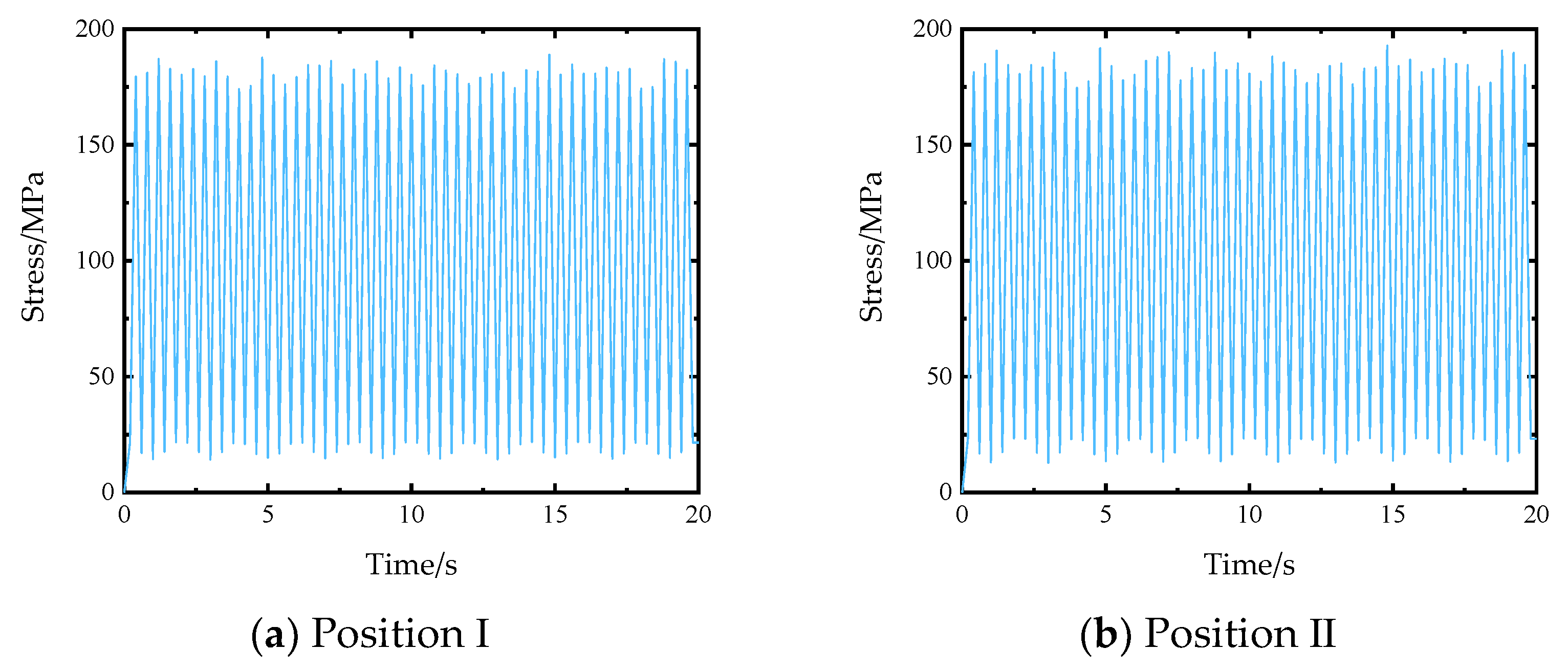
3.2. Application: Fatigue Life Analysis of Stiffened Plates
4. Conclusions
- (1)
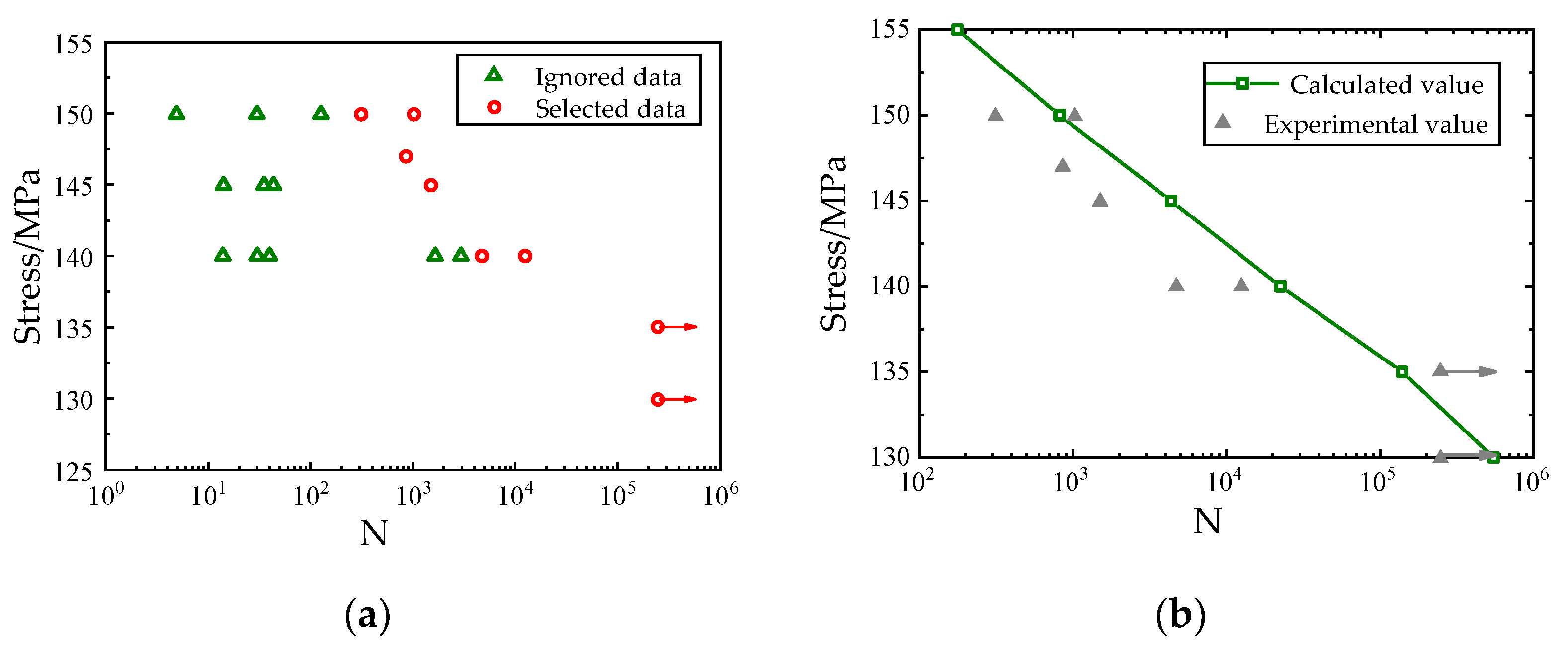
- The fatigue life analysis results of the braided CMCs based on the sub-model are in good agreement with the experimental results in the literature, which proves the accuracy of the micro-cell finite element model of 2D SiC/SiC ceramic matrix braided composites established in this paper.
- (2)
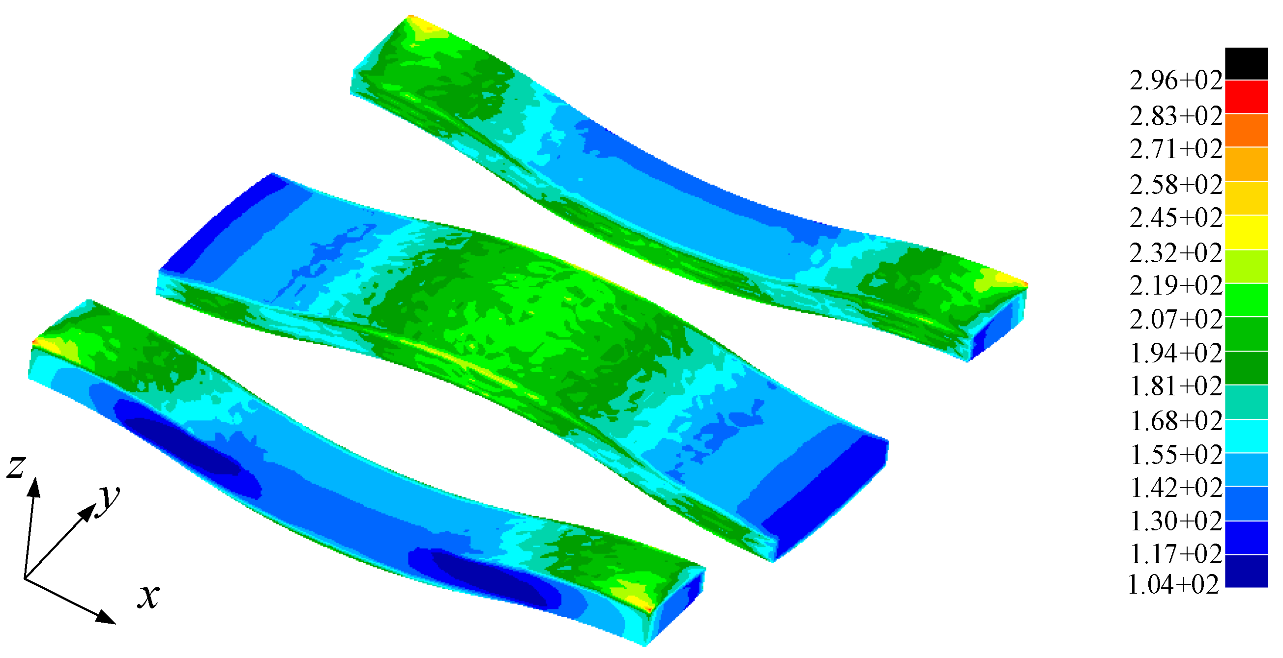
- The multi-scale fatigue method based on dynamic sub-model can reflect the meso-fatigue failure state of ceramic matrix composite materials, and has high computational efficiency. It can calculate the fatigue damage state of multiple positions of the structure, and the requirement for macroscopic modeling is low, only the size of the macro-scale element needs to be similar to the size of the meso-scale model, and the position of mesoscopic model in the macroscopic element has low influence on the fatigue life analysis, which is well applicable to the fatigue life analysis of two-dimensional braided CMC structures.
Author Contributions
Funding
Institutional Review Board Statement
Informed Consent Statement
Data Availability Statement
Acknowledgments
Conflicts of Interest
References
- Shen, X.L.; Qiao, Y.F.; Dong, S.J.; Liu, X.; Gong, L.D. Thermal Load Test Method and Numerical Calculation for Ceramic Matrix Composite Turbine Guide Vane. Appl. Compos. Mater. 2019, 26, 553–573. [Google Scholar] [CrossRef]
- Shi, D.Q.; Jing, X.; Yang, X.G. Low cycle fatigue behavior of a 3D braided KD-I fiber reinforced ceramic matrix composite for coated and uncoated specimens at 1100 degrees C and 1300 degrees C. Mater. Sci. Eng. A Struct. Mater. Prop. Microstruct. Process. 2015, 631, 38–44. [Google Scholar] [CrossRef]
- Jiang, D.; Xu, Y.; Zhu, D.H.; Cao, Z.F. Temperature-dependent thermo-elastic parameter identification for composites using thermal modal data. Adv. Mech. Eng. 2019, 11, 14. [Google Scholar] [CrossRef] [Green Version]
- Chen, S.; Fei, Q.; Jiang, D.; Cao, Z. Determination of thermo-elastic parameters for dynamical modeling of 2.5D C/SiC braided composites. J. Mech. Sci. Technol. 2018, 32, 231–243. [Google Scholar] [CrossRef]
- Jiang, D.; Li, Y.; Fei, Q.; Wu, S. Prediction of uncertain elastic parameters of a braided composite. Compos. Struct. 2015, 126, 123–131. [Google Scholar] [CrossRef]
- Shi, D.Q.; Teng, X.F.; Jing, X.; Lyu, S.Q.; Yang, X.G. A multi-scale stochastic model for damage analysis and performance dispersion study of a 2.5D fiber-reinforced ceramic matrix composites. Compos. Struct. 2020, 248, 16. [Google Scholar] [CrossRef]
- Gu, Y.F. Theoretical analysis of cross-plane lattice thermal conduction in graphite. Chin. Phys. B 2019, 28, 7. [Google Scholar] [CrossRef]
- Dong, S.; Wang, Z.; Zhou, H.; Kan, Y.-M.; Zhang, X.; Ding, Y.; Gao, L.; Wu, B.; Hu, J. Research Progress in SiC-Based Ceramic Matrix Composites. J. Korean Ceram. Soc. 2012, 49, 295–300. [Google Scholar] [CrossRef]
- Yu, J.W.; Fei, Q.G.; Zhang, P.W.; Li, Y.B.; Chen, Q. Fatigue Life of a 2.5D C/SiC Composite Under Tension-Tension Cyclic Loading: Experimental Investigation and Sensitivity Analysis. Acta Mech. Solida Sin. 2021. [Google Scholar] [CrossRef]
- Wu, Z.; Fang, G.; Fu, M.; Chen, X.; Liang, J.; Lv, D. Random fatigue damage accumulation analysis of composite thin-wall structures based on residual stiffness method. Compos. Struct. 2019, 211, 546–556. [Google Scholar] [CrossRef]
- Fang, G.; Gao, X.; Zhang, S.; Xue, J.; Song, Y.; Wang, F. A residual strength model for the fatigue strengthening behavior of 2D needled CMCs. Int. J. Fatigue 2015, 80, 298–305. [Google Scholar] [CrossRef]
- Przybyla, C. CMC Behavior and Life Modeling Workshop Summary Report (Preprint); Air Force Research Lab Wright-Patterson Afb Oh Materials And Manufacturing Directorate: Dayton, OH, USA, 2011. [Google Scholar]
- Min, J.B. Micromechanics Fatigue Damage Analysis Modeling for Fabric Reinforced Ceramic Matrix Composites. In Proceedings of the 54th AIAA/ASME/ASCE/AHS/ASC Structures, Structural Dynamics, and Materials Conference, Boston, MA, USA, 8–11 April 2013. [Google Scholar]
- Min, J.B.; Xue, D.; Shi, Y. Micromechanics modeling for fatigue damage analysis designed for fabric reinforced ceramic matrix composites. Compos. Struct. 2014, 111, 213–223. [Google Scholar] [CrossRef]
- Li, L.B. Fatigue Life Prediction of Fiber-Reinforced Ceramic-Matrix Composites with Different Fiber Preforms at Room and Elevated Temperatures. Materials 2016, 9, 207. [Google Scholar] [CrossRef] [PubMed] [Green Version]
- Li, L.B. Fatigue Life Prediction of 2D Woven Ceramic-Matrix Composites at Room and Elevated Temperatures. J. Mater. Eng. Perform. 2017, 26, 1209–1222. [Google Scholar] [CrossRef]
- Li, L.B. Fatigue life prediction of ceramic-matrix composites. Aircr. Eng. Aerosp. Technol. 2018, 90, 720–726. [Google Scholar] [CrossRef]
- Li, L.B. Damage evolution of carbon fiber-reinforced ceramic-matrix composites with different fiber preforms using the fatigue hysteresis loop area. Text. Res. J. 2018, 88, 532–551. [Google Scholar] [CrossRef]
- Ni, X.; Zhang, Y.; Pan, C. The degradable performance of bile-duct stent based on a continuum damage model: A finite element analysis. Int. J. Numer. Methods Biomed. Eng. 2020, 36, e3370. [Google Scholar] [CrossRef]
- Naderi, M.; Maligno, A. Finite element simulation of fatigue life prediction in carbon/epoxy laminates. J. Compos. Mater. 2013, 47, 475–484. [Google Scholar] [CrossRef]
- Yang, G.; Sun, B.; Gu, B. Large-scale finite element analysis of a 3D angle-interlock woven composite undergoing low-cyclic three-point bending fatigue. J. Text. Inst. 2014, 105, 275–293. [Google Scholar] [CrossRef]
- Wang, Q.; Lin, H.; Geng, P.; Xu, Y.; Wu, J. Multi-scale damage mechanics method for predicting fatigue life of plain-braided C/SiC composites. Compos. Struct. 2020, 254. [Google Scholar] [CrossRef]
- Zhou, Y.; Fei, Q.; Wu, S. Utilization of modal stress approach in random-vibration fatigue evaluation. Proc. Inst. Mech. Eng. Part G J. Aerosp. Eng. 2016, 231, 2603–2615. [Google Scholar] [CrossRef]
- Lang, J.; Cao, W.; Huang, W.; Russell, R.D. A two-dimensional moving finite element method with local refinement based on a posteriori error estimates. Appl. Numer. Math. 2002, 46, 75–94. [Google Scholar] [CrossRef]
- Sun, L.; Zhao, G.Q.; Ma, X.W. Adaptive generation and local refinement methods of three-dimensional hexahedral element mesh. Finite Elem. Anal. Des. 2012, 50, 184–200. [Google Scholar] [CrossRef]
- Wu, L.S.; Wang, X.H. Substructure method for structure modification based upon unit volume energy analysis technique. Finite Elem. Anal. Design 2004, 40, 807–818. [Google Scholar] [CrossRef]
- Xing, Z.; Mita, A. A substructure approach to local damage detection of shear structure. Struct. Control. Health Monit. 2012, 19, 309–318. [Google Scholar] [CrossRef]
- Wang, H.; Li, A.; Guo, T.; Shuang, M.A. Accurate stress analysis on rigid central buckle of long-span suspension bridges based on submodel method. Sci. China Ser. E Technol. Sci. 2009, 52, 1019–1026. [Google Scholar] [CrossRef]
- Daghia, F.; Ladeveze, P. A micro-meso computational strategy for the prediction of the damage and failure of laminates. Compos. Struct. 2012, 94, 3644–3653. [Google Scholar] [CrossRef]
- Bai, B.; Bai, G.C.; Li, C. Application of multi-stage multi-objective multi-disciplinary agent model based on dynamic substructural method in Mistuned Blisk. Aerosp. Sci. Technol. 2015, 46, 104–115. [Google Scholar] [CrossRef]
- Ramsay, A.C.A.; Maunder, E.A.W. Sub-modelling and boundary conditions with p-type hybrid-equilibrium plate-membrane elements. Finite Elem. Anal. Des. 2006, 43, 155–167. [Google Scholar] [CrossRef]
- Mandal, N.K.; Dhanasekar, M. Sub-modelling for the ratchetting failure of insulated rail joints. Int. J. Mech. Sci. 2013, 75, 110–122. [Google Scholar] [CrossRef] [Green Version]
- Jiang, H.; Ren, Y.; Zhang, S.; Liu, Z.; Nie, L. Multi-scale finite element analysis for tension and ballistic penetration damage characterizations of 2D triaxially braided composite. J. Mater. Sci. 2018, 53, 10071–10094. [Google Scholar] [CrossRef]
- Liu, J.; Fei, Q.; Jiang, D.; Zhang, D.; Wu, S. Experimental and numerical investigation on static and dynamic characteristics for curvilinearly stiffened plates using DST–BK model. Int. J. Mech. Sci. 2020, 169, 105286. [Google Scholar] [CrossRef]
- Fantozzi, G.; Reynaud, P. Mechanical hysteresis in ceramic matrix composites. Mater. Sci. Eng. A 2009, 521, 18–23. [Google Scholar] [CrossRef]
- Li, L.B. Fatigue Life Prediction of Carbon Fiber-Reinforced Ceramic-Matrix Composites at Room and Elevated Temperatures. Part II: Experimental Comparisons. Appl. Compos. Mater. 2015, 22, 961–972. [Google Scholar] [CrossRef]
- Curtin, W.A. Theory of Mechanical Properties of Ceramic-Matrix Composites. J. Am. Ceram. Soc. 1991, 74, 2837–2845. [Google Scholar] [CrossRef]
- Evans, A.G.; Zok, F.W.; Mcmeeking, R.M. Fatigue of ceramic matrix composites. Acta Metall. Et Mater. 1995, 43, 859–875. [Google Scholar] [CrossRef]
- Lee, S.S. Damage Analysis and Mechanical Response of As-Received and Heat-Treated Nicalon/CAS-II Glass-Ceramic Matrix Composites. Ph.D. Thesis, Virginia Polytechnic Institute and State University, Montgomery, VA, USA, 1993. [Google Scholar]
- Phoenix, S.L.; Raj, R. Overview no. 100 Scalings in fracture probabilities for a brittle matrix fiber composite. Acta Metall. Et Mater. 1992, 40, 2813–2828. [Google Scholar] [CrossRef]
- Zhou, Y.D.; Hang, X.C.; Wu, S.Q.; Fei, Q.G.; Trisovic, N. Frequency-dependent random fatigue of panel-type structures made of ceramic matrix composites. Acta Mech. Solida Sin. 2017, 30, 165–173. [Google Scholar] [CrossRef]
- Gao, K.; Fu, S.; Gibson, R.L.; Chung, E.T.; Efendiev, Y. Generalized Multiscale Finite-Element Method (GMsFEM) for elastic wave propagation in heterogeneous, anisotropic media. J. Comput. Phys. 2015, 295, 161–188. [Google Scholar] [CrossRef] [Green Version]
- Young, K.H.; Gyu, K.H. Efficient isoparametric trimmed-hexahedral elements with explicit shape functions. Comput. Methods Appl. Mech. Eng. 2020, 372, 113316. [Google Scholar]
- Dasgupta, G. Closed-form isoparametric shape functions of four-nods convex finite elements. J. Aerosp. Eng. 2008, 21, 10–18. [Google Scholar] [CrossRef] [Green Version]
- Hui, X.Y.; Xu, Y.J.; Hou, Y.L. A coupled micro-meso-scale study on the damage mechanism of 2D SiC/SiC ceramic matrix composites. Mech. Adv. Mater. Struct. 2020. [Google Scholar] [CrossRef]
- Mital, S.K.; Murthy, P.L.N.; Chamis, C.C. Simplified micromechanics of plain weave composites. J. Adv. Mater. 2001, 33, 10–17. [Google Scholar]
- Xiong, Y.; Niu, X.M.; Chen, X.H.; Sun, Z.G.; Li, H.Y.; Song, Y.D. A model for predicting residual stiffness of unidirectional SiC/SiC composite under stress oxidation environment. Compos. Interfaces 2020, 27, 753–775. [Google Scholar] [CrossRef]
- Morishita, K.; Ochiai, S.; Okuda, H.; Nakayama, H.; Sato, M. Simulation of fracture behavior of unidirectional SiC/SiC composite exposed in air at 823–1673 K. Compos. Interfaces 2005, 12, 693–706. [Google Scholar] [CrossRef]
- Li, L.B. Effects of Temperature and Oxidation on Cyclic-Fatigue Life of 2D Woven Ceramic-Matrix Composites. J. Aerosp. Eng. 2017, 30, 11. [Google Scholar] [CrossRef]
- Rouby, D.; Reynaud, P. Fatigue behaviour related to interface modification during load cycling in ceramic-matrix fibre composites. Compos. Sci. Technol. 1993, 48, 109–118. [Google Scholar] [CrossRef]


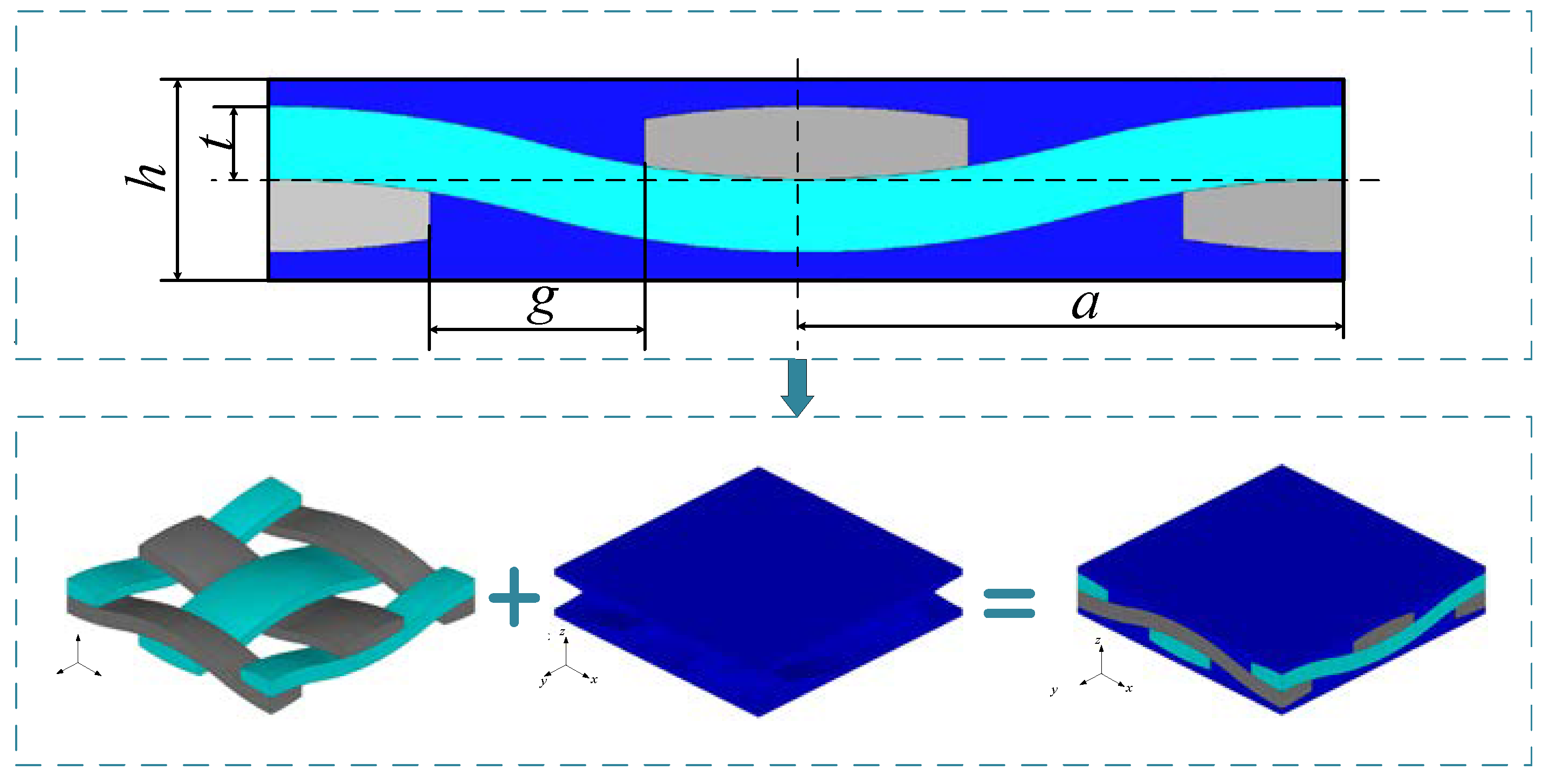
| Meso-Geometric Parameters | t (mm) | g (mm) | a (mm) | h (mm) |
|---|---|---|---|---|
| Value | 0.21 | 0.62 | 1.55 | 0.58 |
| Material Parameters | Yarn | Matrix |
|---|---|---|
| E1(GPa) | 190.01 | 350 |
| E2(GPa) | 190.01 | 350 |
| E3(GPa) | 222.31 | 350 |
| G12(GPa) | 64.78 | 145.8 |
| G13(GPa) | 79.53 | 145.8 |
| G23(GPa) | 79.53 | 145.8 |
| ν12 | 0.16 | 0.25 |
| ν13 | 0.17 | 0.25 |
| ν23 | 0.17 | 0.25 |
| Parameter | τmin (MPa) | τ(0) (MPa) | ω1 | ω2 | mf | Vf |
|---|---|---|---|---|---|---|
| Value | 5 | 50 | 0.04 | 1 | 2 | 0.4 |
| E1/GPa | E2/GPa | E3/GPa | G12/GPa | G13/GPa | G23/GPa | ν12 | ν13 | ν23 | ρ/(g/cm3) |
|---|---|---|---|---|---|---|---|---|---|
| 229.76 | 229.76 | 189.78 | 92.15 | 72.58 | 72.58 | 0.16 | 0.17 | 0.17 | 2.5 |
| Amount of Damage D | Life T | |
|---|---|---|
| Fatigue hot spot A | 0.000863654 | 23,157.42 s |
| Fatigue hot spot B | 0.000394991 | 50,634.07 s |
| Fatigue hot spot C | 0.000178935 | 111,772.43 s |
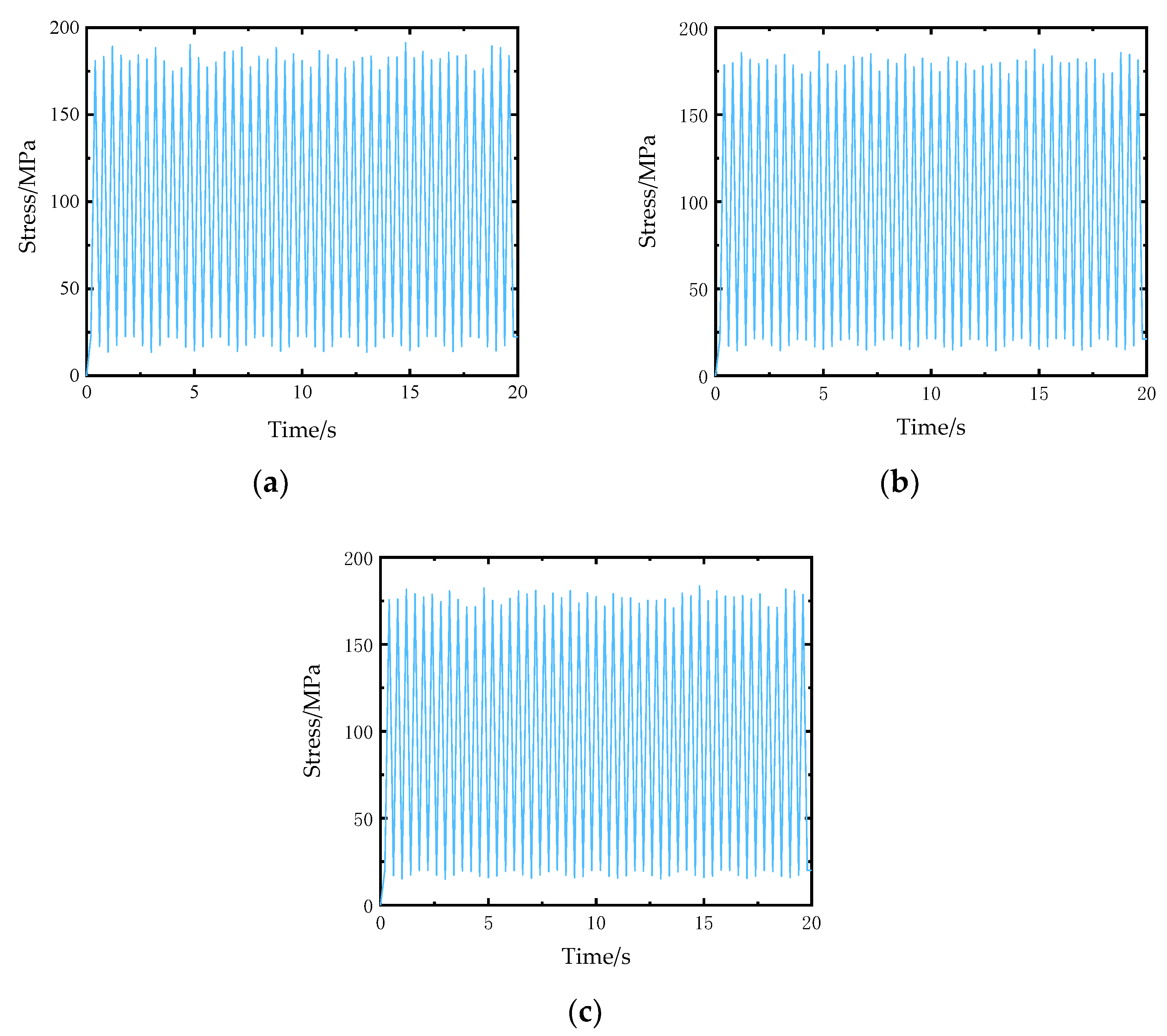
| Fatigue Damage D | Life T | |
|---|---|---|
| Position I | 0.0006534 | 30,607.95 s |
| Position II | 0.00110485 | 18,101.96 s |
Publisher’s Note: MDPI stays neutral with regard to jurisdictional claims in published maps and institutional affiliations. |
© 2021 by the authors. Licensee MDPI, Basel, Switzerland. This article is an open access article distributed under the terms and conditions of the Creative Commons Attribution (CC BY) license (https://creativecommons.org/licenses/by/4.0/).
Share and Cite
Zheng, J.; Zhang, P.; Zhang, D.; Jiang, D. A Multi-Scale Submodel Method for Fatigue Analysis of Braided Composite Structures. Materials 2021, 14, 4190. https://doi.org/10.3390/ma14154190
Zheng J, Zhang P, Zhang D, Jiang D. A Multi-Scale Submodel Method for Fatigue Analysis of Braided Composite Structures. Materials. 2021; 14(15):4190. https://doi.org/10.3390/ma14154190
Chicago/Turabian StyleZheng, Jincheng, Peiwei Zhang, Dahai Zhang, and Dong Jiang. 2021. "A Multi-Scale Submodel Method for Fatigue Analysis of Braided Composite Structures" Materials 14, no. 15: 4190. https://doi.org/10.3390/ma14154190