The Multidirectional Auxeticity and Negative Linear Compressibility of a 3D Mechanical Metamaterial

 , , and
Abstract
:1. Introduction
2. Methods
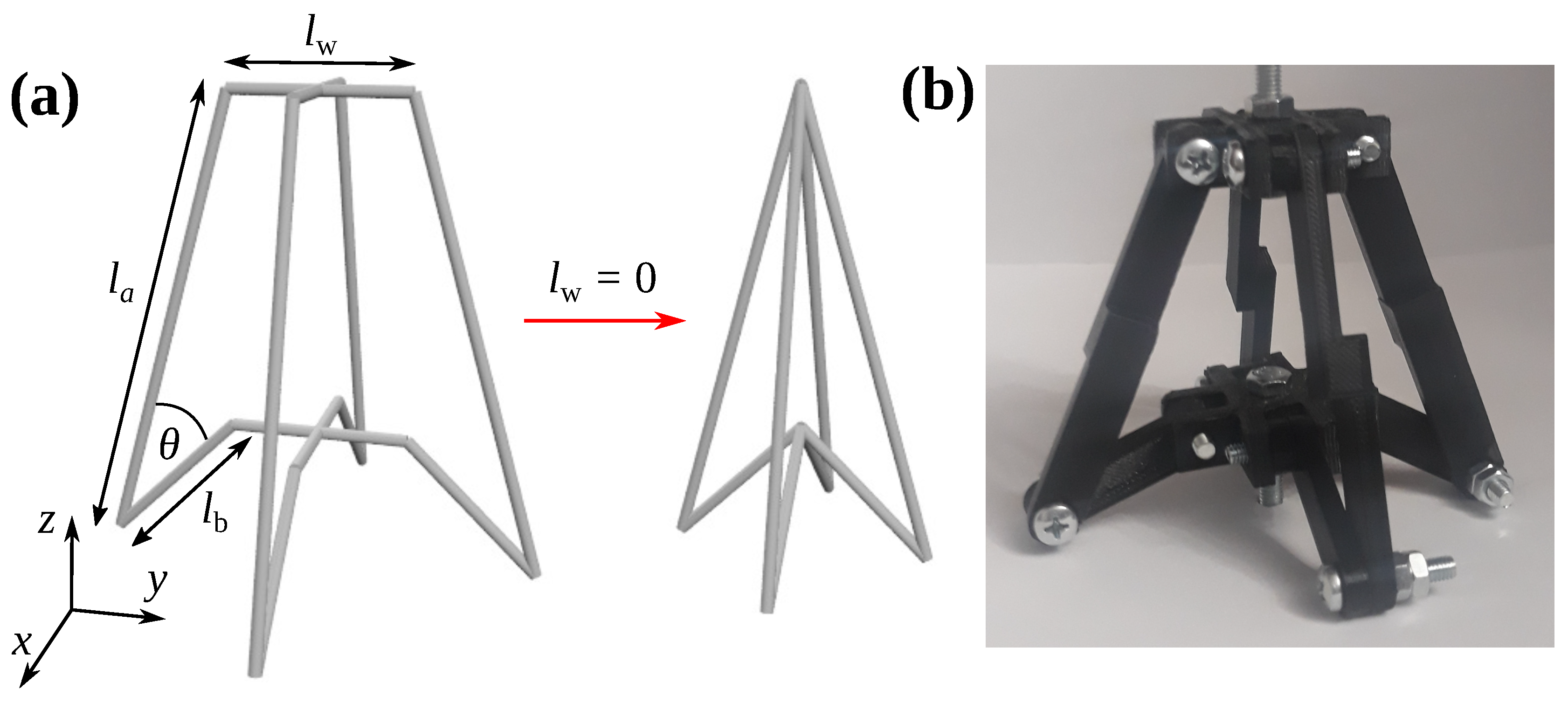
2.1. Geometry
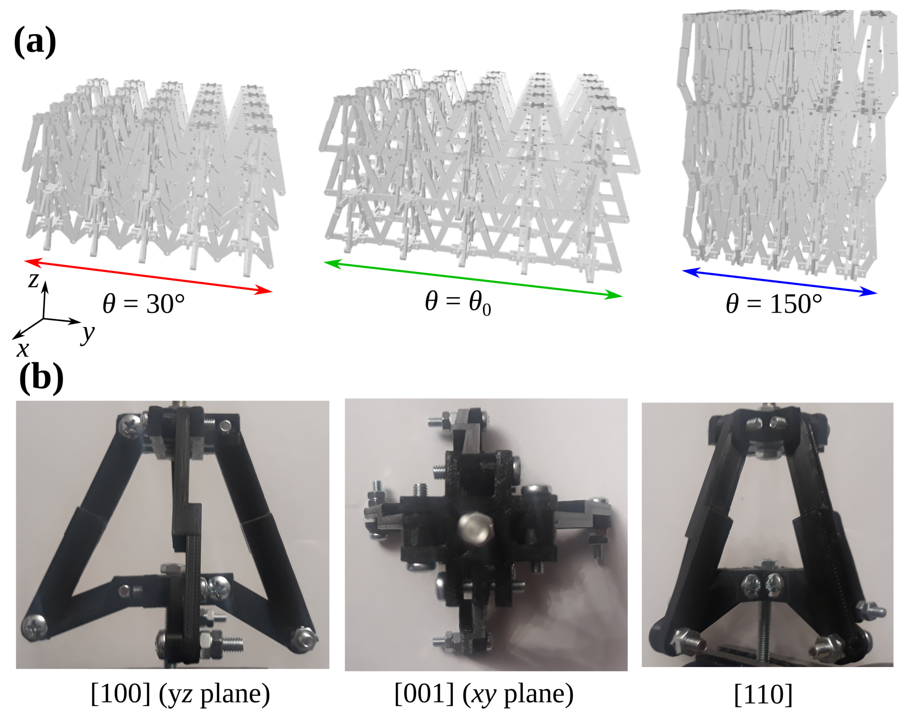
2.2. Deformation Process
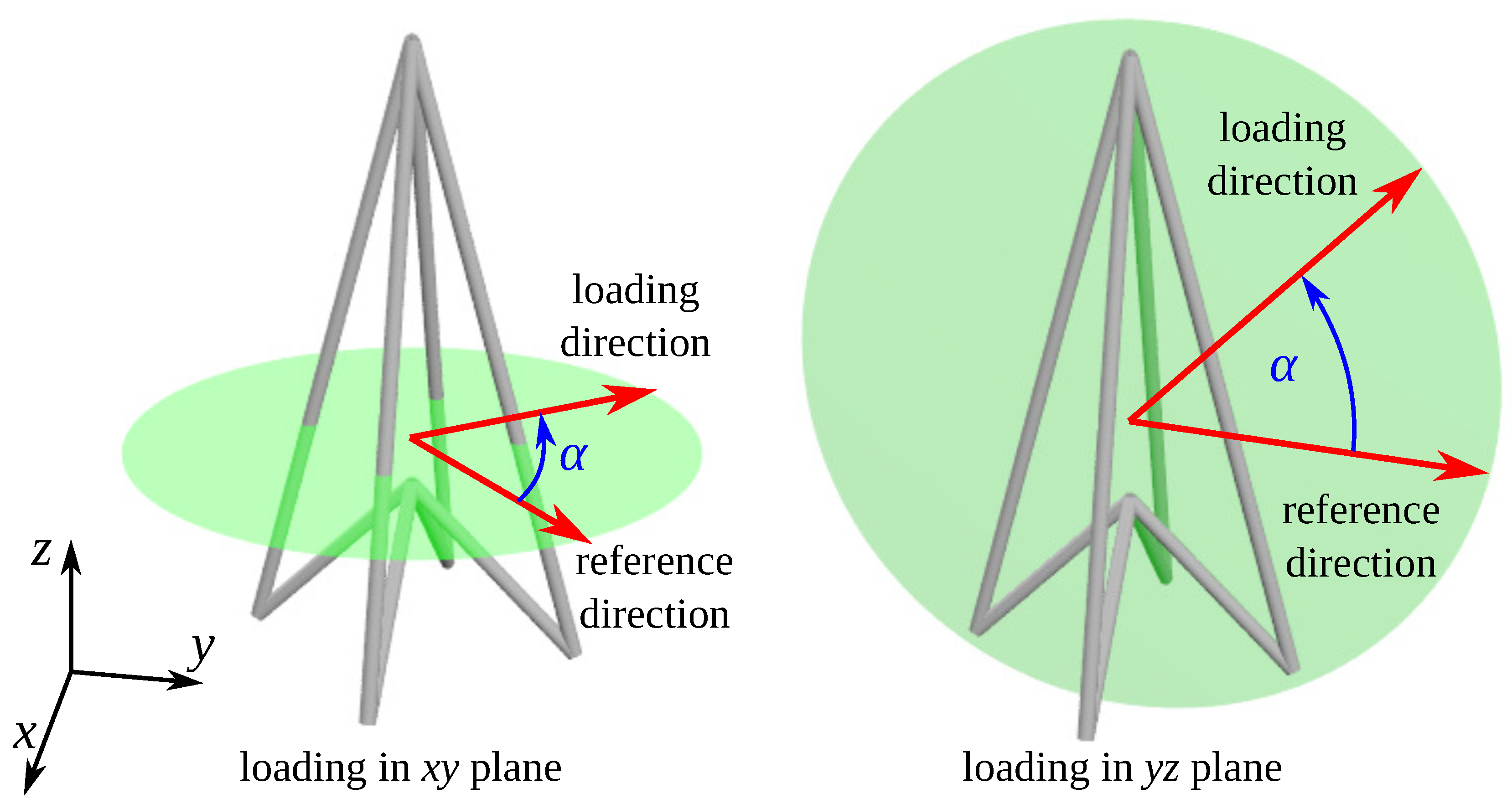
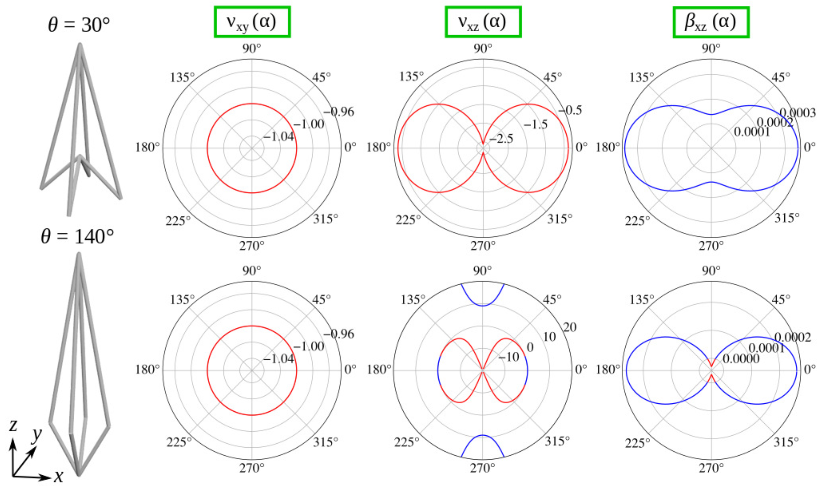
2.3. Mechanical Properties
2.4. Prototype
2.5. Parameters
3. Results and Discussion
4. Conclusions
Author Contributions
Funding
Acknowledgments
Conflicts of Interest
Abbreviations
| NLC | Negative Linear Compressibility |
Appendix A. Design of The Prototype

Appendix B. Theoretical Results Corresponding to Parameters Used in the Experiment

References
- Evans, K.E.; Nkansah, M.A.; Hutchinson, I.J.; Rogers, S.C. Molecular Network Design. Nature 1991, 353, 124. [Google Scholar] [CrossRef]
- Zadpoor, A.A. Mechanical meta-materials. Mater. Horiz. 2016, 3, 371–381. [Google Scholar] [CrossRef] [Green Version]
- Cummer, S.A.; Christensen, J.; Alú, A. Controlling sound with acoustic metamaterials. Nat. Rev. Mater. 2016, 1, 16001. [Google Scholar] [CrossRef] [Green Version]
- Tang, Y.; Ren, S.; Meng, H.; Xin, F.; Huang, L.; Chen, T.; Zhang, C.; Lu, T.J. Hybrid acoustic metamaterial as super absorber for broadband low-frequency sound. Sci. Rep. 2017, 7, 43340. [Google Scholar] [CrossRef] [PubMed] [Green Version]
- Zangeneh-Nejad, F.; Fleury, R. Active times for acoustic metamaterials. Rev. Phys. 2019, 4, 100031. [Google Scholar] [CrossRef]
- Kolken, H.M.A.; Janbaz, S.; Leeflang, S.M.A.; Lietaert, K.; Weinans, H.H.; Zadpoor, A.A. Rationally designed meta-implants: A combination of auxetic and conventional meta-biomaterials. Mater. Horiz. 2018, 5, 28–35. [Google Scholar] [CrossRef] [Green Version]
- Lakes, R. Foam structures with a negative Poisson’s ratio. Science 1987, 235, 1038. [Google Scholar] [CrossRef]
- Imbalzano, G.; Linforth, S.; Ngo, T.D.; Lee, P.V.S.; Tran, P. Blast resistance of auxetic and honeycomb sandwich panels: Comparisons and parametric designs. Compos. Struct. 2018, 183, 242–261. [Google Scholar] [CrossRef]
- Dudek, K.K.; Wolak, W.; Gatt, R.; Grima, J. Impact resistance of composite magnetic metamaterials. Sci. Rep. 2019, 9, 3963. [Google Scholar] [CrossRef] [Green Version]
- Al-Rifaie, H.; Sumelka, W. The Development of a New Shock Absorbing Uniaxial Graded Auxetic Damper (UGAD). Materials 2019, 12, 2573. [Google Scholar] [CrossRef] [Green Version]
- Pasala, D.T.R.; Sarlis, A.A.; Nagarajaiah, A.M.; Reinhorn, M.C.; Constantinou, M.C.; Taylor, D. Adaptive Negative Stiffness: New Structural Modification Approach for Seismic Protection. J. Struct. Eng. 2012, 139, 1112–1123. [Google Scholar] [CrossRef]
- Wang, Y.; Wang, L.; Ma, Z.-D.; Wang, T. A negative Poisson’s ratio suspension jounce bumper. Mater. Des. 2016, 103, 90–99. [Google Scholar] [CrossRef]
- Duncan, O.; Foster, L.; Senior, T.; Alderson, A.; Allen, T. Quasi-static characterisation and impact testing of auxetic foam for sports safety applications. Smart Mater. Struct. 2016, 25, 054014. [Google Scholar] [CrossRef]
- Almgren, F. An isotropic three-dimensional structure with Poisson’s ratio = −1. J. Elast. 1985, 15, 427–430. [Google Scholar]
- Evans, K.E.; Alderson, A. Auxetic Materials: Functional Materials and Structures from Lateral Thinking! Adv. Mater. 2000, 12, 617–628. [Google Scholar] [CrossRef]
- Scarpa, F.; Panayiotou, P.; Tomlinson, G. Numerical and experimental uniaxial loading on in-plane auxetic honeycombs. J. Strain Anal. Eng. 2000, 35, 383–388. [Google Scholar] [CrossRef]
- Wojciechowski, K.W. Two-dimensional isotropic system with a negative Poisson ratio. Phys. Lett. A 1989, 137, 60–64. [Google Scholar] [CrossRef]
- Bertoldi, K.; Reis, P.M.; Willshaw, S.; Mullin, T. Negative Poisson’s Ratio Behavior Induced by an Elastic Instability. Adv. Mater. 2010, 22, 361–366. [Google Scholar] [CrossRef] [Green Version]
- Lim, T.-C. Analogies across auxetic models based on deformation mechanism. Phys. Status Solidi RRL 2017, 11, 1600440. [Google Scholar] [CrossRef]
- Strek, T.; Jopek, H.; Idczak, E.; Wojciechowski, K.W. Computational Modelling of Structures with Non-Intuitive Behaviour. Materials 2017, 10, 1386. [Google Scholar] [CrossRef] [Green Version]
- Lim, T.-C. Auxeticity of Concentric Auxetic-Conventional Foam Rods with High Modulus Interface Adhesive. Materials 2018, 11, 223. [Google Scholar] [CrossRef] [PubMed] [Green Version]
- Xue, Y.; Gao, P.; Zhou, L.; Han, F. An Enhanced Three-Dimensional Auxetic Lattice Structure with Improved Property. Materials 2020, 13, 1008. [Google Scholar] [CrossRef] [PubMed] [Green Version]
- Mizzi, L.; Salvati, E.; Spaggiari, A.; Tan, J.-C.; Korsunsky, A.M. Highly stretchable two-dimensional auxetic metamaterial sheets fabricated via direct-laser cutting. Int. J. Mech. Sci. 2020, 167, 105242. [Google Scholar] [CrossRef]
- Lakes, R.S.; Drugan, W.J. Dramatically stiffer elastic composite materials due to a negative stiffness phase? J. Mech. Phys. Solids 2002, 50, 979–1009. [Google Scholar] [CrossRef]
- Florijn, B.; Coulais, C.; van Hecke, M. Programmable mechanical metamaterials. Phys. Rev. Lett. 2014, 113, 175–503. [Google Scholar] [CrossRef] [Green Version]
- Hewage, T.A.M.; Alderson, K.L.; Alderson, A.; Scarpa, F. Double-negative mechanical metamaterials displaying simultaneous negative stiffness and negative Poissons ratio properties. Adv. Mater. 2016, 28, 10323. [Google Scholar] [CrossRef]
- Dudek, K.K.; Gatt, R.; Dudek, M.R.; Grima, J.N. Negative and positive stiffness in auxetic magneto-mechanical metamaterials. Proc. R. Soc. A 2018, 474, 20180003. [Google Scholar] [CrossRef]
- Dudek, K.K.; Gatt, R.; Grima, J.N. 3D composite metamaterial with magnetic inclusions exhibiting negative stiffness and auxetic behaviour. Mater. Des. 2020, 187, 108403. [Google Scholar] [CrossRef]
- Baughman, R.H.; Stafstrom, S.; Cui, C.; Dantas, S.O. Materials with negative compressibilities in one or more dimensions. Science 1998, 279, 1522–1524. [Google Scholar] [CrossRef]
- Lakes, R.; Wojciechowski, K.W. Negative compressibility, negative Poisson’s ratio, and stability. Phys. Status Solidi B 2008, 245, 545–551. [Google Scholar] [CrossRef]
- Nicolaou, Z.G.; Motter, A.E. Mechanical metamaterials with negative compressibility transitions. Nat. Mater. 2012, 11, 608–613. [Google Scholar] [CrossRef] [PubMed]
- Dudek, K.K.; Attard, D.; Caruana-Gauci, R.; Wojciechowski, K.W.; Grima, J.N. Unimode metamaterials exhibiting negative linear compressibility and negative thermal expansion. Smart Mater. Struct. 2016, 25, 025009. [Google Scholar] [CrossRef]
- Zhou, Z.; Zhang, L.; Zhang, H.; Liu, Q.; Ren, T. 3D cellular models with negative compressibility through the wine-rack-type mechanism. Phys. Status Solidi B 2016, 253, 1977–1993. [Google Scholar] [CrossRef]
- Qu, J.; Kadic, M.; Wegener, M. Poroelastic metamaterials with negative effective static compressibility. Appl. Phys. Lett. 2017, 110, 171901. [Google Scholar] [CrossRef]
- Lim, T.-C. 2D Structures Exhibiting Negative Area Compressibility. Phys. Status Solidi B 2017, 254, 1600682. [Google Scholar] [CrossRef]
- Welche, P.R.L.; Heine, V.; Dove, M.T. Negative thermal expansion in beta-quartz. Phys. Chem. Miner. 1998, 26, 63–77. [Google Scholar] [CrossRef]
- Evans, J.S.O.; Mary, T.A.; Sleight, A.W. Negative Thermal Expansion in Sc2(WO4)3. J. Solid State Chem. 1998, 137, 148–160. [Google Scholar] [CrossRef]
- Grima, J.N.; Evans, K.E. Auxetic behavior from rotating squares. J. Mater. Sci. 2000, 19, 1563–1565. [Google Scholar]
- Grima, J.N.; Gatt, R.; Alderson, A.; Evans, K.E. On the auxetic properties of ‘rotating rectangles’ with different connectivity. J. Phys. Soc. Jpn. 2005, 74, 2866–2867. [Google Scholar] [CrossRef]
- Grima, J.N.; Chetcuti, E.; Manicaro, E.; Attard, D.; Camilleri, M.; Gatt, R.; Evans, K.E. On the auxetic properties of generic rotating rigid triangles. Proc. R. Soc. A 2012, 468, 810–830. [Google Scholar] [CrossRef]
- Lee, J.-H.; Singer, J.P.; Thomas, E.L. Micro-/Nanostructured Mechanical Metamaterials. Adv. Mater. 2012, 24, 4782–4810. [Google Scholar] [CrossRef] [PubMed]
- Zheng, X.; Smith, W.; Jackson, J.; Moran, B.; Cui, H.; Chen, D.; Ye, J.; Fang, N.; Rodriguez, N.; Weisgraber, T.; et al. Multiscale metallic metamaterials. Nat. Mater. 2016, 15, 1100–1106. [Google Scholar] [CrossRef] [PubMed]
- Bückmann, T.; Stenger, N.; Kadic, M.; Kaschke, J.; Frölich, A.; Kennerknecht, T.; Eberl, C.; Thiel, M.; Wegener, M. Tailored 3D Mechanical Metamaterials Made by Dip-in Direct-Laser-Writing Optical Lithography. Adv. Mater. 2012, 24, 2710–2714. [Google Scholar] [CrossRef] [PubMed]
- Bückmann, T.; Schittny, R.; Thiel, M.; Kadic, M.; Milton, G.W.; Wegener, M. On three-dimensional dilational elastic metamaterials. New J. Phys. 2014, 16, 033032. [Google Scholar] [CrossRef] [Green Version]
- Zheng, X.; Lee, H.; Weisgraber, T.H.; Shusteff, M.; DeOtte, J.; Duoss, E.B.; Kuntz, J.D.; Biener, M.M.; Ge, Q.; Jackson, J.A.; et al. Ultralight, ultrastiff mechanical metamaterials. Science 2014, 344, 1373–1377. [Google Scholar] [CrossRef] [PubMed] [Green Version]
- Frenzel, T.; Kadic, M.; Wegener, M. Three-dimensional mechanical metamaterials with a twist. Science 2017, 358, 1072–1074. [Google Scholar] [CrossRef] [PubMed] [Green Version]
- Fernandez-Corbaton, I.; Rockstuhl, C.; Ziemke, P.; Gumbsch, P.; Albiez, A.; Schwaiger, R.; Frenzel, T.; Kadic, M.; Wegener, M. New twists of 3d chiral metamaterials. Adv. Mater. 2019, 31, 1807742. [Google Scholar] [CrossRef] [Green Version]
- Brunet, T.; Merlin, A.; Mascaro, B.; Zimny, K.; Leng, J.; Poncelet, O.; Aristégui, C.; Mondain-Monval, O. Soft 3D acoustic metamaterial with negative index. Nat. Mater. 2015, 14, 384–388. [Google Scholar] [CrossRef]
- Qu, J.; Kadic, M.; Naber, A.; Wegener, M. Micro-Structured Two-Component 3D Metamaterials with Negative Thermal-Expansion Coefficient from Positive Constituents. Sci. Rep. 2017, 7, 40643. [Google Scholar] [CrossRef]
- Jackson, J.A.; Messner, M.C.; Dudukovic, N.A.; Smith, W.L.; Bekker, L.; Moran, B.; Golobic, A.M.; Pascall, A.J.; Duoss, E.B.; Loh, K.J.; et al. Field responsive mechanical metamaterials. Sci. Adv. 2018, 4, eaau6419. [Google Scholar] [CrossRef] [Green Version]
- Jiang, Y.; Wang, Q. Highly-stretchable 3D-architected Mechanical Metamaterials. Sci. Rep. 2016, 6, 34147. [Google Scholar] [CrossRef] [PubMed] [Green Version]
- Bertoldi, K.; Vitelli, V.; Christensen, J.; van Hecke, M. Flexible mechanical metamaterials. Nat. Rev. Mater. 2017, 2, 17066. [Google Scholar] [CrossRef] [Green Version]
- Evans, K.E.; Nkansah, M.A.; Hutchinson, I.J. Auxetic foams: Modelling negative Poisson’s ratios. Acta Metall. Mater. 1994, 42, 1289–1294. [Google Scholar] [CrossRef]
- Attard, D.; Grima, J. A three-dimensional rotating rigid units network exhibiting negative Poisson’s ratios. Phys. Status Solidi B 2012, 249, 1330–1338. [Google Scholar] [CrossRef]
- Babaee, S.; Shim, J.; Weaver, J.C.; Chen, E.R.; Patel, N.; Bertoldi, K. 3D Soft Metamaterials with Negative Poisson’s Ratio. Adv. Mater. 2013, 25, 5044–5049. [Google Scholar] [CrossRef]
- Yasuda, H.; Yang, J. Reentrant Origami-Based Metamaterials with Negative Poisson’s Ratio and Bistability. Phys. Rev. Lett. 2015, 114, 185502. [Google Scholar] [CrossRef] [Green Version]
- Yang, L.; Harrysson, O.; West, H.; Cormier, D. Mechanical properties of 3D re-entrant honeycomb auxetic structures realized via additive manufacturing. Int. J. Solids Struct. 2015, 69–70, 475–490. [Google Scholar] [CrossRef]
- Yuan, S.; Chua, C.K.; Zhou, K. 3D-Printed Mechanical Metamaterials with High Energy Absorption. Adv. Mater. Technol. 2018, 4, 1800419. [Google Scholar] [CrossRef]
- Soo Ha, C.; Lakes, R.S.; Plesha, M.E. Cubic negative stiffness lattice structure for energy absorption: Numerical and experimental studies. Int. J. Solids Struct. 2019, 178–179, 127–135. [Google Scholar]
- Mohsenizadeh, M.; Gasbarri, F.; Munther, M.; Beheshti, A.; Davami, K. Additively-manufactured lightweight Metamaterials for energy absorption. Mater. Des. 2018, 139, 521–530. [Google Scholar] [CrossRef]
- Cui, S.; Gong, B.; Ding, Q.; Sun, Y.; Ren, F.; Liu, X.; Yan, Q.; Yang, H.; Wang, X.; Song, B. Mechanical Metamaterials Foams with Tunable Negative Poisson’s Ratio for Enhanced Energy Absorption and Damage Resistance. Materials 2018, 11, 1869. [Google Scholar] [CrossRef] [PubMed] [Green Version]
- Larsen, U.D.; Sigmund, O.; Bouwsta, S. Design and fabrication of compliant micromechanisms and structures with negative Poisson’s ratio. J. Microelectromech. Syst. 1997, 6, 99–106. [Google Scholar] [CrossRef] [Green Version]
- Lim, T.-C. A 3D auxetic material based on intersecting double arrowheads. Phys. Status Solidi B 2016, 253, 1252–1260. [Google Scholar] [CrossRef]
- Chen, Y.-L.; Wang, X.-T.; Ma, L. Damping mechanisms of CFRP three-dimensional double-arrow-head auxetic metamaterials. Polym. Test. 2020, 81, 106189. [Google Scholar] [CrossRef]
- Nye, J.F. Physical Properties of Crystals: Their Representation by Tensors and Matrices; Clarendon Press: Oxford, UK, 1957. [Google Scholar]
- Grima-Cornish, J.N.; Grima, J.N.; Attard, D. A Novel Mechanical Metamaterial Exhibiting Auxetic Behavior and Negative Compressibility. Materials 2020, 13, 79. [Google Scholar] [CrossRef] [Green Version]
- Masters, I.G.; Evans, K.E. Models for the elastic deformation of honeycombs. Compos. Struct. 1996, 35, 403–422. [Google Scholar] [CrossRef]
- Wojciechowski, K.W. Remarks on “Poisson Ratio beyond the Limits of the Elasticity Theory”. J. Phys. Soc. Jpn. 2003, 72, 1819–1820. [Google Scholar] [CrossRef]
- Dudek, M.R.; Dudek, K.K.; Wolak, W.; Wojciechowski, K.W.; Grima, J.N. Magnetocaloric materials with ultra-small magnetic nanoparticles working at room temperature. Sci. Rep. 2019, 9, 17607. [Google Scholar] [CrossRef]


© 2020 by the authors. Licensee MDPI, Basel, Switzerland. This article is an open access article distributed under the terms and conditions of the Creative Commons Attribution (CC BY) license (http://creativecommons.org/licenses/by/4.0/).
Share and Cite
Dudek, K.K.; Attard, D.; Gatt, R.; Grima-Cornish, J.N.; Grima, J.N. The Multidirectional Auxeticity and Negative Linear Compressibility of a 3D Mechanical Metamaterial. Materials 2020, 13, 2193. https://doi.org/10.3390/ma13092193
Dudek KK, Attard D, Gatt R, Grima-Cornish JN, Grima JN. The Multidirectional Auxeticity and Negative Linear Compressibility of a 3D Mechanical Metamaterial. Materials. 2020; 13(9):2193. https://doi.org/10.3390/ma13092193
Chicago/Turabian StyleDudek, Krzysztof K., Daphne Attard, Ruben Gatt, James N. Grima-Cornish, and Joseph N. Grima. 2020. "The Multidirectional Auxeticity and Negative Linear Compressibility of a 3D Mechanical Metamaterial" Materials 13, no. 9: 2193. https://doi.org/10.3390/ma13092193