A Proposal for a Composite with Temperature-Independent Thermophysical Properties: HfV2–HfV2O7

 , , , , and
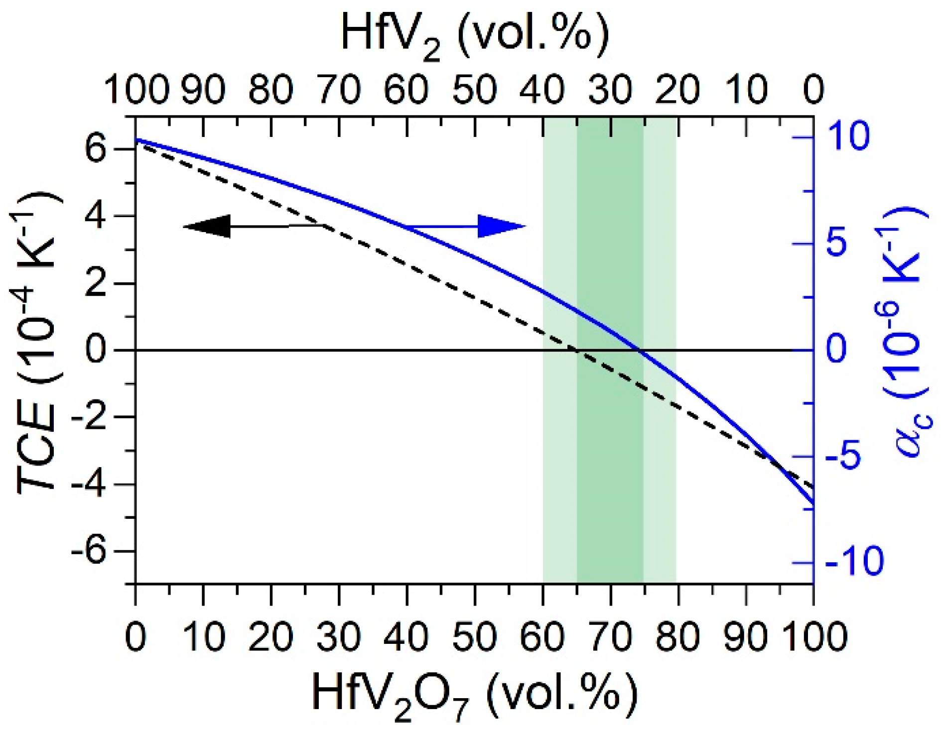
Abstract
:1. Introduction
2. Materials and Methods
2.1. Experimental Methods
2.2. Theoretical Methods
3. Results and Discussion
3.1. Composite Assessment
3.2. Composite Formation by Oxidation of HfV2
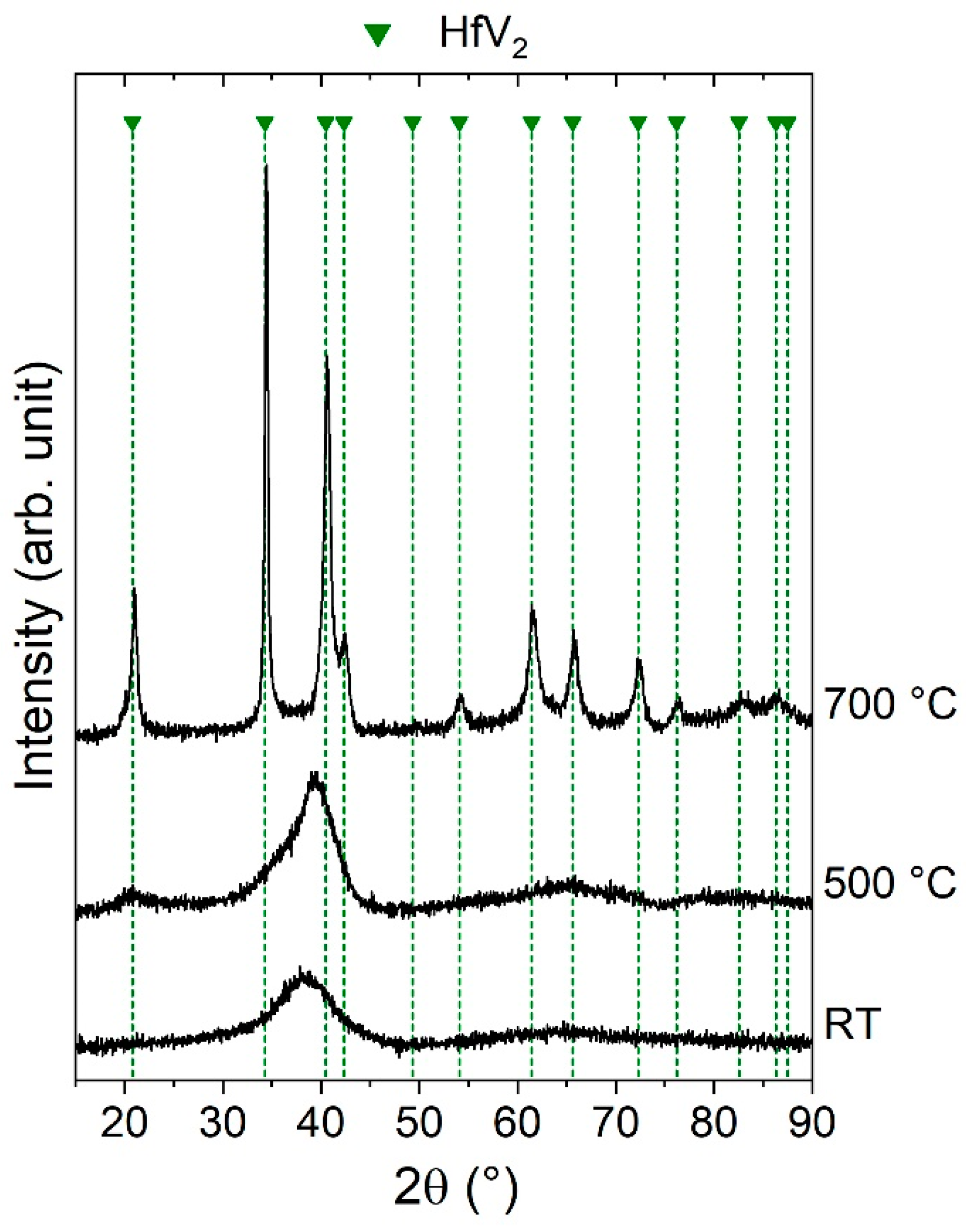
3.2.1. Phase Formation of HfV2
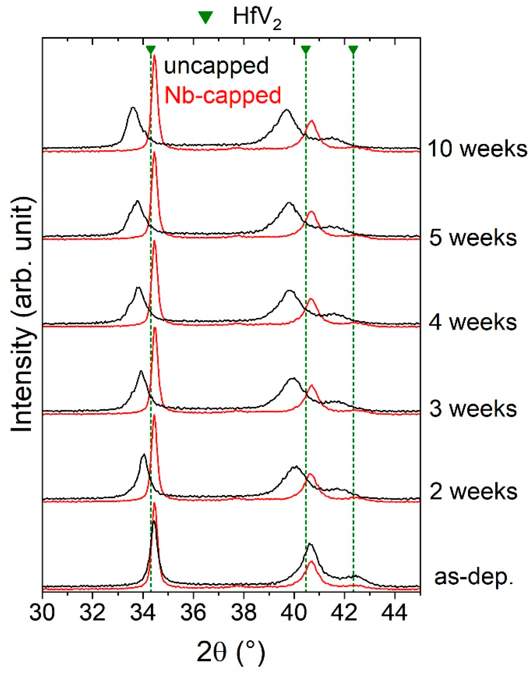
3.2.2. Stability of HfV2
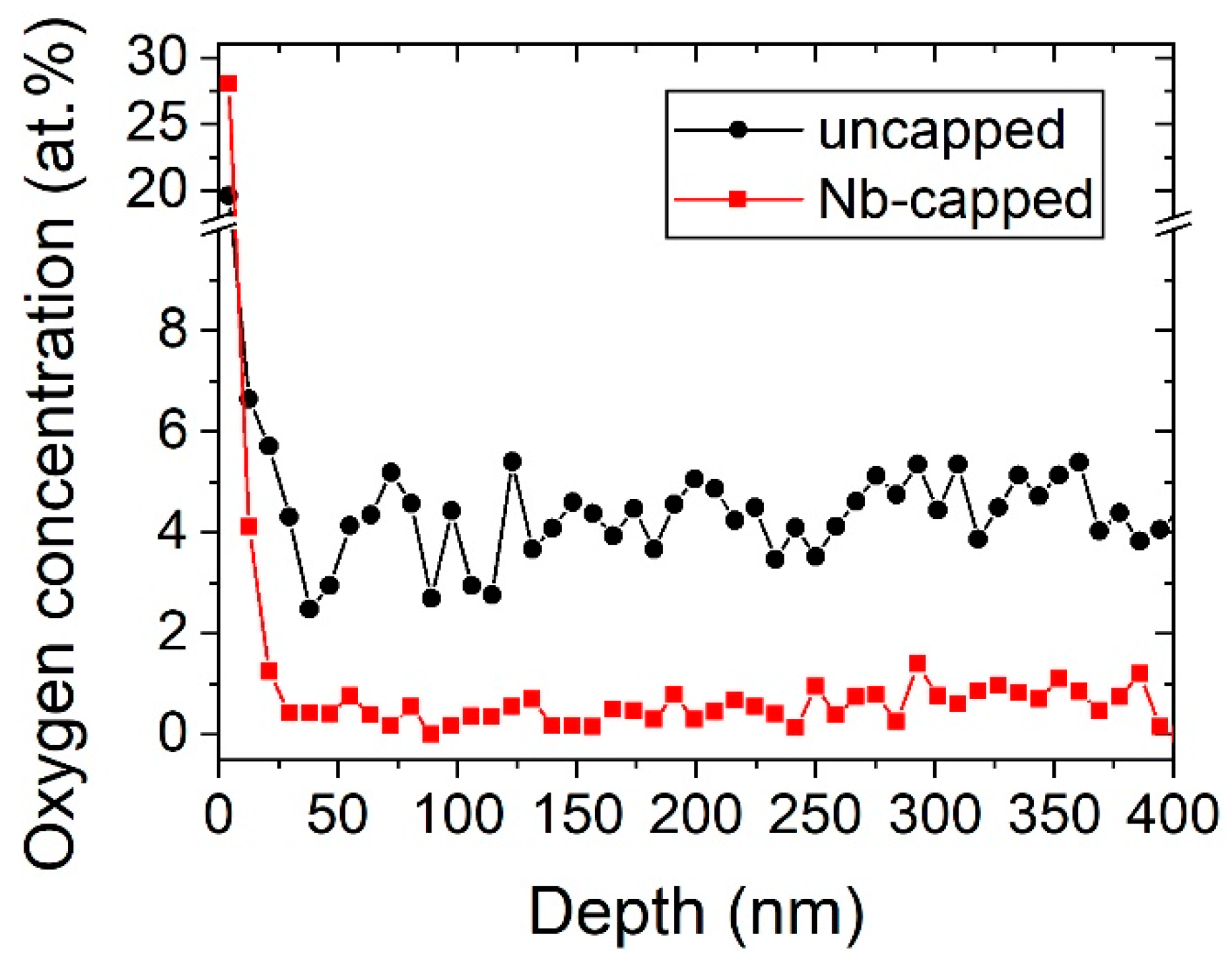
3.2.3. Oxidation of HfV2
3.3. Composite Formation by Sputtering of Bilayered HfV2–HfV2O7
3.3.1. Phase Formation of HfV2O7
3.3.2. Thermal Expansion of Sputtered HfV2O7
3.3.3. Phase Formation of HfV2–HfV2O7 Bilayers
4. Conclusions
Author Contributions
Funding
Conflicts of Interest
References
- Roy, R.; Agrawal, D.K.; McKinstry, H.A. Very low thermal expansion coefficient materials. Annu. Rev. Mater. Sci. 1989, 19, 59–81. [Google Scholar] [CrossRef]
- Wolff, E.G. Thermal expansion in metal/lithia-alumina-silica (LAS) composites. Int. J. Thermophys. 1988, 9, 221–232. [Google Scholar] [CrossRef]
- Mandal, S.; Chakrabarti, S.; Das, S.K.; Ghatak, S. Synthesis of low expansion ceramics in lithia–alumina–silica system with zirconia additive using the powder precursor in the form of hydroxyhydrogel. Ceram. Int. 2007, 33, 123–132. [Google Scholar] [CrossRef]
- Lind, C. Two decades of negative thermal expansion research: Where do we stand? Materials 2012, 5, 1125–1154. [Google Scholar] [CrossRef]
- Takenaka, K. Negative thermal expansion materials: Technological key for control of thermal expansion. Sci. Technol. Adv. Mater. 2012, 13, 013001. [Google Scholar] [CrossRef]
- Feng Huang, L.; Zeng, Z. Lattice dynamics and disorder-induced contraction in functionalized graphene. J. Appl. Phys. 2013, 113, 083524. [Google Scholar] [CrossRef]
- Saito, T.; Furuta, T.; Hwang, J.-H.; Kuramoto, S.; Nishino, K.; Suzuki, N.; Chen, R.; Yamada, A.; Ito, K.; Seno, Y.; et al. Multifunctional alloys obtained via a dislocation-free plastic deformation mechanism. Science 2003, 300, 464–467. [Google Scholar] [CrossRef] [Green Version]
- Cahn, R.W. An unusual Nobel Prize. Notes Rec. R. Soc. 2005, 59, 145–153. [Google Scholar] [CrossRef]
- Wang, Y.; Gao, J.; Wu, H.; Yang, S.; Ding, X.; Wang, D.; Ren, X.; Wang, Y.; Song, X.; Gao, J. Strain glass transition in a multifunctional β-type Ti alloy. Sci. Rep. 2014, 4, 3995. [Google Scholar] [CrossRef] [Green Version]
- Oh, J.M.; Kang, J.-H.; Lee, S.; Kim, S.-D.; Kang, N.; Park, C.H. Origin of superproperties of Ti-23Nb-1Ta-2Hf-O alloy. Mater. Lett. 2018, 233, 162–165. [Google Scholar] [CrossRef]
- Qin, F.; Lu, F.; Chen, Y.; Yang, J.; Zhao, X. Deformation induced elinvar behavior in Fe–Ni invar alloy. Sci. Bull. 2018, 63, 1040–1042. [Google Scholar] [CrossRef] [Green Version]
- Dove, M.T.; Fang, H. Negative thermal expansion and associated anomalous physical properties: Review of the lattice dynamics theoretical foundation. Rep. Prog. Phys. 2016, 79, 066503. [Google Scholar] [CrossRef] [PubMed]
- Grimvall, G. Thermophysical Properties of Materials; Elsevier Science B.V.: Amsterdam, The Netherlands, 1999. [Google Scholar] [CrossRef]
- Wachtman, J.B.; Tefft, W.E.; Lam, D.G.; Apstein, C.S. Exponential temperature dependence of young’s modulus for several oxides. Phys. Rev. 1961, 122, 1754–1759. [Google Scholar] [CrossRef]
- Chen, J.; Nittala, K.; Forrester, J.S.; Jones, J.L.; Deng, J.; Yu, R.; Xing, X. The role of spontaneous polarization in the negative thermal expansion of tetragonal PbTiO3-based compounds. J. Am. Chem. Soc. 2011, 133, 11114–11117. [Google Scholar] [CrossRef]
- Yamada, I.; Tsuchida, K.; Ohgushi, K.; Hayashi, N.; Kim, J.; Tsuji, N.; Takahashi, R.; Matsushita, M.; Nishiyama, N.; Inoue, T.; et al. Giant negative thermal expansion in the iron perovskite SrCu3Fe4O12. Angew. Chem. Int. Ed. 2011, 50, 6579–6582. [Google Scholar] [CrossRef]
- Romao, C.P.; Miller, K.J.; Whitman, C.A.; White, M.A. Comprehensive Inorganic Chemistry II Negative Thermal Expansion (Thermomiotic) Materials; Elsevier: Oxford, UK, 2013; Volume 4, pp. 128–151. [Google Scholar]
- Takenaka, K.; Takagi, H. Giant negative thermal expansion in Ge-doped anti-perovskite manganese nitrides. Appl. Phys. Lett. 2005, 87, 261902. [Google Scholar] [CrossRef]
- Walker, E. Anomalous temperature behaviour of the shear elastic constant C44 in vanadium. Solid State Commun. 1978, 28, 587–589. [Google Scholar] [CrossRef]
- Armstrong, P.E.; Dickinson, J.M.; Brown, H.L. Temperature dependence of the elastic stiffness coefficients of niobium (columbium). Trans. Am. Inst. Min. Metall. Pet. Eng. 1966, 236, 1404. [Google Scholar]
- Walker, E.; Bujard, P. Anomalous temperature behaviour of the shear elastic constant C44 in tantalum. Solid State Commun. 1980, 34, 691–693. [Google Scholar] [CrossRef]
- Rayne, J.A. Elastic Constants of Palladium from 4.2-300 K. Phys. Rev. 1960, 118, 1545–1549. [Google Scholar] [CrossRef]
- Macfarlane, R.E.; Rayne, J.A.; Jones, C.K. Anomalous temperature dependence of shear modulus C44 for Platinum. Phys. Lett. 1965, 18, 91–92. [Google Scholar] [CrossRef]
- Walker, E.; Ortelli, J.; Peter, M. Elastic constants of monocrystalline alloys of Pd–Rh and Pd–Ag between 4.2 K and 300 K. Phys. Lett. A 1970, 31, 240–241. [Google Scholar] [CrossRef]
- Ashkenazi, J.; Dacorogna, M.; Peter, M.; Talmor, Y.; Walker, E.; Steinemann, S. Elastic constants in Nb–Zr alloys from zero temperature to the melting point: Experiment and theory. Phys. Rev. B 1978, 18, 4120–4131. [Google Scholar] [CrossRef]
- Bujard, P.; Sanjines, R.; Walker, E.; Ashkenazi, J.; Peter, M. Elastic constants in Nb–Mo alloys from zero temperature to the melting point: Experiment and theory. J. Phys. F 1981, 11, 775. [Google Scholar] [CrossRef]
- Keuter, P.; Music, D.; Schnabel, V.; Stuer, M.; Schneider, J.M. From qualitative to quantitative description of the anomalous thermoelastic behavior of V, Nb, Ta, Pd and Pt. J. Phys.: Condens. Matter 2019, 31, 225402. [Google Scholar] [CrossRef]
- Keuter, P.; Music, D.; Stuer, M.; Schneider, J.M. Electronic structure tuning of the anomalous thermoelastic behavior in Nb–X (X = Zr, V, Mo) solid solutions. J. Appl. Phys. 2019, 125, 215103. [Google Scholar] [CrossRef]
- Keuter, P.; Music, D.; Stuer, M.; Schneider, J.M. Temperature and impurity induced stabilization of cubic HfV2 laves phase. Condens. Matter 2019, 4, 63. [Google Scholar] [CrossRef] [Green Version]
- Huang, L.; Vitos, L.; Kwon, S.K.; Johansson, B.; Ahuja, R. Thermoelastic properties of random alloys from first-principles theory. Phys. Rev. B 2006, 73, 104203. [Google Scholar] [CrossRef]
- Huang, L.; Ramzan, M.; Vitos, L.; Johansson, B.; Ahuja, R. Anomalous temperature dependence of elastic constant c44 in V, Nb, Ta, Pd, and Pt. J. Phys. Chem. Solids 2010, 71, 1065–1068. [Google Scholar] [CrossRef]
- Lüthi, B.; Herrmann, M.; Assmus, W.; Schmidt, H.; Rietschel, H.; Wühl, H.; Gottwick, U.; Sparn, G.; Steglich, F. Normal-state and superconducting properties of HfV2. Z. Phys. B Condens. Matter 1985, 60, 387–392. [Google Scholar] [CrossRef]
- Rudy, E.; Windisch, S. The phase diagrams hafnium-vanadium and hafnium-chromium. J. Less Common. Met. 1968, 15, 13–27. [Google Scholar] [CrossRef]
- Finlayson, T.R.; Lanston, E.J.; Simpson, M.A.; Gibbs, E.E.; Smith, T.F. Elastic properties of (Hf,Zr)V2 superconducting compounds. J. Phys. F 1978, 8, 2269. [Google Scholar] [CrossRef]
- Balankin, A.S.; Skorov, D.M. Anomalies of elastic moduli in ZrV2 and HfV2 Laves phases at high temperatures. Sov. Phys. Solid State 1982, 24, 681–682. [Google Scholar]
- Pushkarev, E.A.; Petrenko, N.S.; Finkel, V.A. Thermal expansion of the superconducting compound HfV2 at low temperatures. Phys. Status Solidi A 1978, 47, K145–K148. [Google Scholar] [CrossRef]
- Attfield, J.P. Mechanisms and Materials for NTE. Front. Chem. 2018, 6. [Google Scholar] [CrossRef] [PubMed] [Green Version]
- Mary, T.A.; Evans, J.S.O.; Vogt, T.; Sleight, A.W. Negative thermal expansion from 0.3 to 1050 Kelvin in ZrW2O8. Science 1996, 272, 90–92. [Google Scholar] [CrossRef] [Green Version]
- Evans, J.S.O.; Mary, T.A.; Sleight, A.W. Negative thermal expansion materials. Phys. B Condens. Matter 1997, 241–243, 311–316. [Google Scholar] [CrossRef]
- Hisashige, T.; Yamaguchi, T.; Tsuji, Y.; Yamamura, T. Phase Transition of Zr1−xHfxV2O7 solid solutions having negative thermal expansion. J. Ceram. Soc. Jpn. 2006, 114, 607–611. [Google Scholar] [CrossRef] [Green Version]
- Turquat, C.; Muller, C.; Nigrelli, E.; Leroux, C.; Soubeyroux, J.L.; Nihoul, G. Structural investigation of temperature-induced phase transitions in HfV2O7. Eur. Phys. J. Appl. Phys. 2000, 10, 15–27. [Google Scholar] [CrossRef]
- Sutton, M.S.; Talghader, J. Micromachined negative thermal expansion thin films. J. Microelectromechanical Syst. 2004, 13, 1148–1151. [Google Scholar] [CrossRef]
- Liu, H.; Yang, L.; Zhang, Z.; Pan, K.; Zhang, F.; Cheng, H.; Zeng, X.; Chen, X. Preparation and optical, nanomechanical, negative thermal expansion properties of Sc2W3O12 thin film grown by pulsed laser deposition. Ceram. Int. 2016, 42, 8809–8814. [Google Scholar] [CrossRef]
- Liu, H.; Zhang, Z.; Zhang, W.; Chen, X.; Cheng, X. Negative thermal expansion ZrW2O8 thin films prepared by pulsed laser deposition. Surf. Coat. Technol. 2011, 205, 5073–5076. [Google Scholar] [CrossRef]
- Liu, H.; Pan, K.; Jin, Q.; Zhang, Z.; Wang, G.; Zeng, X. Negative thermal expansion and shift in phase transition temperature in Mo-substituted ZrW2O8 thin films prepared by pulsed laser deposition. Ceram. Int. 2014, 40, 3873–3878. [Google Scholar] [CrossRef]
- Bespalov, I.; Datler, M.; Buhr, S.; Drachsel, W.; Rupprechter, G.; Suchorski, Y. Initial stages of oxide formation on the Zr surface at low oxygenpressure: An in situ FIM and XPS study. Ultramicroscopy 2015, 159, 147–151. [Google Scholar] [CrossRef] [Green Version]
- Laguna, O.H.; Pérez, A.; Centeno, M.A.; Odriozola, J.A. Synergy between gold and oxygen vacancies in gold supported on Zr-doped ceria catalysts for the CO oxidation. Appl. Catal. B 2015, 176–177, 385–395. [Google Scholar] [CrossRef] [Green Version]
- Schneider, J.M.; Hjörvarsson, B.; Wang, X.; Hultman, L. On the effect of hydrogen incorporation in strontium titanate layers grown by high vacuum magnetron sputtering. Appl. Phys. Lett. 1999, 75, 3476–3478. [Google Scholar] [CrossRef]
- Ravensburg, A.L.; Keuter, P.; Music, D.; Miljanovic, D.J.; Schneider, J.M. Experimental and Theoretical Investigation of the Elastic Properties of HfV2O7. Crystals 2020, 10, 172. [Google Scholar] [CrossRef] [Green Version]
- Zhang, Y.; Whitlow, H.J.; Winzell, T.; Bubb, I.F.; Sajavaara, T.; Arstila, K.; Keinonen, J. Detection efficiency of time-of-flight energy elastic recoil detection analysis systems. Nucl. Instrum. Methods Phys. Res. B 1999, 149, 477–489. [Google Scholar] [CrossRef]
- Janson, M.S. Contes Instruction Manual; Uppsala University: Uppsala, Sweden, 2004. [Google Scholar]
- Bragg, W.H.; Bragg, W.L. The reflection of X-rays by crystals. Proc R. Soc. Lond. Ser. A Contain. Pap. Math. Phys. Character 1913, 88, 428–438. [Google Scholar] [CrossRef]
- Langford, R.M.; Rogers, M. In situ lift-out: Steps to improve yield and a comparison with other FIB TEM sample preparation techniques. Micron 2008, 39, 1325–1330. [Google Scholar] [CrossRef]
- Hohenberg, P.; Kohn, W. Inhomogeneous electron gas. Phys. Rev. 1964, 136, B864–B871. [Google Scholar] [CrossRef] [Green Version]
- Kresse, G.; Hafner, J. Ab initio molecular dynamics for open-shell transition metals. Phys. Rev. B 1993, 48, 13115–13118. [Google Scholar] [CrossRef] [PubMed]
- Kresse, G.; Hafner, J. Ab initio molecular-dynamics simulation of the liquid-metal-amorphous-semiconductor transition in germanium. Phys. Rev. B 1994, 49, 14251–14269. [Google Scholar] [CrossRef] [PubMed]
- Perdew, J.P.; Burke, K.; Ernzerhof, M. Generalized gradient approximation made simple. Phys. Rev. Lett. 1996, 77, 3865–3868. [Google Scholar] [CrossRef] [Green Version]
- Monkhorst, H.J.; Pack, J.D. Special points for Brillouin-zone integrations. Phys. Rev. B 1976, 13, 5188–5192. [Google Scholar] [CrossRef]
- Birch, F. Finite Eastic Strain of Cubic Crystals. Phys. Rev. 1947, 71, 809–824. [Google Scholar] [CrossRef]
- Murnaghan, F.D. The compressibility of media under extreme pressures. Proc. Natl. Acad. Sci. USA 1944, 15, 244–247. [Google Scholar] [CrossRef] [Green Version]
- Drymiotis, F.R.; Ledbetter, H.; Betts, J.B.; Kimura, T.; Lashley, J.C.; Migliori, A.; Ramirez, A.P.; Kowach, G.R.; Van Duijn, J. Monocrystal elastic constants of the negative-thermal-expansion compound zirconium tungstate (ZrW2O8). Phys. Rev. Lett. 2004, 93, 025502. [Google Scholar] [CrossRef]
- De Buysser, K.; Lommens, P.; De Meyer, C.; Bruneel, E.; Hoste, S.; Van Driessche, I. ZrO2-ZrW2O8 composites with tailor-made thermal expansion. Ceram. Silik. 2004, 48, 139–144. [Google Scholar]
- Evans, J.S.O.; Mary, T.A.; Vogt, T.; Subramanian, M.A.; Sleight, A.W. Negative thermal expansion in ZrW2O8 and HfW2O8. Chem. Mater. 1996, 8, 2809–2823. [Google Scholar] [CrossRef]
- Yamamura, Y.; Horikoshi, A.; Yasuzuka, S.; Saitoh, H.; Saito, K. Negative thermal expansion emerging upon structural phase transition in ZrV2O7 and HfV2O7. Dalt. Trans. 2011, 40, 2242–2248. [Google Scholar] [CrossRef] [PubMed]
- Romao, C.P.; Marinkovic, B.A.; Werner-Zwanziger, U.; White, M.A. Thermal expansion reduction in alumina-toughened zirconia by incorporation of zirconium tungstate and aluminum tungstate. J. Am. Ceram. Soc. 2015, 98, 2858–2865. [Google Scholar] [CrossRef]
- Kingery, W.D.; Bowen, H.K.; Uhlmann, D.R. Introduction to Ceramics; Wiley: New York, NY, USA, 1960. [Google Scholar]
- Chen, H.-Y.; Lu, F.-H. Oxidation behavir of titanium nitride films. J. Vac. Sci. Technol. A 2005, 23. [Google Scholar] [CrossRef] [Green Version]
- Stelzer, B.; Momma, M.; Schneider, J.M. Autonomously Self-Reporting Hard Coatings: Tracking the temporal oxidation behavior of tin by in situ sheet resistance measurements. Adv. Funct. Mater. 2020, 30, 2000146. [Google Scholar] [CrossRef]
- Eickert, S.; Hecht, H.; von Minnigerode, G. Formation area of amorphous thin V−Zr films prepared by cocondensation on hot substrates. Z. Phys. B Condens. Matter 1992, 88, 35–38. [Google Scholar] [CrossRef]
- Shi, L.Q.; Xu, S.L. Phase transformations of sputtered ZrV2 films after annealing and hydrogenation. J. Vac. Sci. Technol. A 2006, 24, 190–194. [Google Scholar] [CrossRef]
- King, D.J.M.; Middleburgh, S.C.; Liu, A.C.Y.; Tahini, H.A.; Lumpkin, G.R.; Cortie, M.B. Formation and structure of V–Zr amorphous alloy thin films. Acta Mater. 2015, 83, 269–275. [Google Scholar] [CrossRef]
- Chihi, T.; Fatmi, M.; Ghebouli, B. Ab initio calculations for properties of laves phase V2M (M = Zr, Hf, Ta) compounds. Am. J. Mod. Phys. 2013, 2, 88–92. [Google Scholar] [CrossRef]
- Lumley, S.C.; Murphy, S.T.; Burr, P.A.; Grimes, R.W.; Chard-Tuckey, P.R.; Wenman, M.R. The stability of alloying additions in Zirconium. J. Nucl. Mater. 2013, 437, 122–129. [Google Scholar] [CrossRef]
- Levy, O.; Hart, G.L.W.; Curtarolo, S. Hafnium binary alloys from experiments and first principles. Acta Mater. 2010, 58, 2887–2897. [Google Scholar] [CrossRef] [Green Version]
- Vřešťál, J.; Pavlů, J.; Wdowik, U.D.; Šob, M. Modelling of phase equilibria in the Hf-V system below room temperature. J. Min. Metall. Sect. B Metall. 2017, 53, 239–247. [Google Scholar] [CrossRef] [Green Version]
- Parsons, M.J.; Brown, P.J.; Crangle, J.; Neumann, K.U.; Ouladdiaf, B.; Smith, T.J.; Zayer, N.K.; Ziebeck, K.R.A. A study of the structural phase transformation and superconductivity in HfV2. J. Phys. Condens. Matter 1998, 10, 8523. [Google Scholar] [CrossRef]
- Zhao, Y.; Chu, F.; Von Dreele, R.B.; Zhu, Q. Structural phase transitions of HfV2 at low temperatures. Acta Crystallogr. Sect. B Struct. Sci. 2000, 56, 601–606. [Google Scholar] [CrossRef]
- Rapp, Ö.; Benediktsson, G. Latent heat of structural transformations in ZrV2 and HfV2. Phys. Lett. A 1979, 74, 449–452. [Google Scholar] [CrossRef]
- Kim, W.-Y.; Luzzi, D.E.; Pope, D.P. Room temperature deformation behavior of the Hf-V–Ta C15 Laves phase. Intermetallics 2003, 11, 257–267. [Google Scholar] [CrossRef]
- Bolvardi, H.; Emmerlich, J.; Mráz, S.; Arndt, M.; Rudigier, H.; Schneider, J.M. Low temperature synthesis of Mo2BC thin films. Thin Solid Films 2013, 542, 5–7. [Google Scholar] [CrossRef]
- Smith, T.F.; Shelton, R.N.; Lawson, A.C. Superconductivity and structural instability of (Hf, Zr)V2 and (Hf, Ta)V2 alloys at high pressure. J. Phys. F 1973, 3, 2157. [Google Scholar] [CrossRef]
- Forker, M.; Herz, W.; Simon, D. Impurity trapping in the laves phase HfV2 detected by perturbed angular correlations. J. Phys. Condens. Matter 1992, 4, 213. [Google Scholar] [CrossRef]
- Greczynski, G.; Petrov, I.; Greene, J.E.; Hultman, L. Al capping layers for nondestructive x-ray photoelectron spectroscopy analyses of transition-metal nitride thin films. J. Vac. Sci. Technol. A 2015, 33, 05E101. [Google Scholar] [CrossRef] [Green Version]
- Cramer, S.D.; Covino, B.S. ASM Metals Handbook—Corrosion: Fundamentals, Testing, and Protection; ASM International: Materials Park Campus, OH, USA, 2003; Volume 13A. [Google Scholar]
- Kang, Y.-B. Critical evaluation and thermodynamic optimization of the VO–VO2.5 system. J. Eur. Ceram. Soc. 2012, 32, 3187–3198. [Google Scholar] [CrossRef]
- Wang, J.; Li, H.P.; Stevens, R. Hafnia and hafnia-toughened ceramics. J. Mater. Sci. 1992, 27, 5397–5430. [Google Scholar] [CrossRef]
- Turquat, C.; Leroux, C.; Gloter, A.; Serin, V.; Nihoul, G. V-doped HfO2: Thermal stability and vanadium valence. Int. J. Inorg. Mater. 2001, 3, 1025–1032. [Google Scholar] [CrossRef]
- Turquat, C.; Leroux, C.; Roubin, M.; Nihoul, G. Vanadium-doped hafnia: Elaboration and structural characterization. Solid State Sci. 1999, 1, 3–13. [Google Scholar] [CrossRef]
- Manory, R.; Mori, T.; Shimizu, I.; Miyake, S.; Kimmel, G. Growth and structure control of HfO2−x films with cubic and tetragonal strucutres obtained by ion beam assisted deposition. J. Vac. Sci. Technol. A 2002, 20. [Google Scholar] [CrossRef]
- Hemamala, U.L.C.; El-Ghussein, F.; Goedken, A.M.; Chen, B.; Leroux, C.; Kruger, M.B. High-pressure x-ray diffraction and Raman spectroscopy of HfV2O7. Phys. Rev. B 2004, 70, 70. [Google Scholar] [CrossRef]
- Pryde, A.K.A.; Hammonds, K.D.; Dove, M.T.; Heine, V.; Gale, J.D.; Warren, M.C. Origin of the negative thermal expansion in ZrW2O8 and ZrV2O7. J. Phys. Condens. Matter 1996, 8, 10973–10982. [Google Scholar] [CrossRef]
- Mittal, R.; Chaplot, S.L. Lattice dynamica calculation of negative thermal expansion in ZrV2O7 and HfV2O7. Phys. Rev. B 2008, 78. [Google Scholar] [CrossRef]
- Korthuis, V.; Khosrovani, N.; Sleight, A.W.; Roberts, N.; Dupree, R.; Warren, W.W., Jr. Negative Thermal expansion and phase transitions in the ZrV2-xPxO7 series. Chem. Mater. 1995, 7, 412–417. [Google Scholar] [CrossRef]
- Evans, J.S.O.; Hanson, J.C.; Sleight, A.W. Room-temperature superstructure of ZrV2O7. Acta Crystallogr. Sect. B 1998, 54, 705–713. [Google Scholar] [CrossRef] [Green Version]
- Khosrovani, N.; Sleight, A.W.; Vogt, T. Structure of ZrV2O7 from −263 to 470 °C. J. Solid State Chem. 1997, 132, 355–360. [Google Scholar] [CrossRef]
- Withers, R.L.; Evans, J.S.O.; Hanson, J.; Sleight, A.W. An in situ temperature-dependent electron and X-ray diffraction study of structural phase transitions in ZrV2O7. J. Solid State Chem. 1998, 137, 161–167. [Google Scholar] [CrossRef]
- Baran, E.J. The unit cell of hafnium divanadate. J. Less Common. Met. 1976, 46, 343–345. [Google Scholar] [CrossRef]


Publisher’s Note: MDPI stays neutral with regard to jurisdictional claims in published maps and institutional affiliations. |
© 2020 by the authors. Licensee MDPI, Basel, Switzerland. This article is an open access article distributed under the terms and conditions of the Creative Commons Attribution (CC BY) license (http://creativecommons.org/licenses/by/4.0/).
Share and Cite
Keuter, P.; Ravensburg, A.L.; Hans, M.; Karimi Aghda, S.; Holzapfel, D.M.; Primetzhofer, D.; Schneider, J.M. A Proposal for a Composite with Temperature-Independent Thermophysical Properties: HfV2–HfV2O7. Materials 2020, 13, 5021. https://doi.org/10.3390/ma13215021
Keuter P, Ravensburg AL, Hans M, Karimi Aghda S, Holzapfel DM, Primetzhofer D, Schneider JM. A Proposal for a Composite with Temperature-Independent Thermophysical Properties: HfV2–HfV2O7. Materials. 2020; 13(21):5021. https://doi.org/10.3390/ma13215021
Chicago/Turabian StyleKeuter, Philipp, Anna L. Ravensburg, Marcus Hans, Soheil Karimi Aghda, Damian M. Holzapfel, Daniel Primetzhofer, and Jochen M. Schneider. 2020. "A Proposal for a Composite with Temperature-Independent Thermophysical Properties: HfV2–HfV2O7" Materials 13, no. 21: 5021. https://doi.org/10.3390/ma13215021