Preparation and Corrosion Behavior in Marine Environment of MAO Coatings on Magnesium Alloy


Abstract
:1. Introduction
2. Materials and Methods
3. Results and Discussions
4. Conclusions
Author Contributions
Funding
Conflicts of Interest
References
- Ding, W.J. Science and Technology of Magnesium Alloy; Science Press: Beijing, China, 2007; pp. 1–10. (In Chinese) [Google Scholar]
- Yi, A.H.; Du, J.; Wang, J.; Mu, S.L.; Zhang, G.G.; Li, W.F. Preparation and characterization of colored Ti/Zr conversion coating on AZ91D magnesium alloy. Surf. Coat. Technol. 2015, 276, 239–247. [Google Scholar] [CrossRef]
- Li, O.; Tsunakawa, M.; Shimada, Y.; Nakamura, K.; Nishinaka, K.; Ishizaki, T. Corrosion resistance of composite oxide film prepared on Ca-added flame-resistant magnesium alloy AZCa612 by micro-arc oxidation. Corros. Sci. 2017, 125, 99–105. [Google Scholar] [CrossRef]
- Zhang, C.Y.; Zeng, R.C.; Liu, C.L.; Gao, J.C. Comparison of calcium phosphatecoatings on Mg-Al and Mg-Ca alloys and their corrosion behavior in Hank’s solution, Surf. Coat. Technol. 2010, 204, 3636–3640. [Google Scholar]
- Cui, Z.Y.; Ge, F.; Lin, Y.; Wang, L.W.; Lei, L.; Tian, H.Y.; Yu, M.D.; Wang, X. Corrosion behavior of AZ31 magnesium alloy in the chloride solution containing ammonium nitrate. Electrochim. Acta 2018, 278, 421–437. [Google Scholar] [CrossRef]
- Sadeghi, A.; Hasanpur, E.; Bahmani, A.; Shin, K.S. Corrosion behaviour of AZ31 magnesium alloy containing various levels of strontium. Corros. Sci. 2018, 141, 117–126. [Google Scholar] [CrossRef]
- Qu, Q.; Li, S.L.; Li, L.; Zuo, L.M.; Ran, X.; Qu, Y.; Zhu, B.L. Adsorption and corrosion behaviour of Ttrichoderma harzianum for AZ31B magnesium alloy in artificial seawater. Corros. Sci. 2017, 118, 12–23. [Google Scholar] [CrossRef]
- Arthanari, S.; Shin, K.S. A simple one step cerium conversion coating formation on to magnesium alloy and electrochemical corrosion performance. Surf. Coat. Technol. 2018, 349, 757–772. [Google Scholar] [CrossRef]
- Wu, L.; Yang, D.N.; Zhang, G.; Zhang, Z.; Zhang, S.; Tang, A.T.; Pan, F.S. Fabrication and characterization of Mg-M layered double hydroxide films on anodized magnesium alloy AZ31. Appl. Surf. Sci. 2018, 431, 177–186. [Google Scholar] [CrossRef]
- Zhang, R.F.; Zhang, S.F. Formation of micro-arc oxidation coatings on AZ91HP magnesium alloys. Corros. Sci. 2009, 51, 2820–2825. [Google Scholar] [CrossRef]
- Yang, W.; Xu, D.P.; Wang, J.L.; Yao, X.F.; Chen, J. Microstructure and corrosion resistance of micro arc oxidation plus electrostatic powder spraying composite coating on magnesium alloy. Corros. Sci. 2018, 136, 174–179. [Google Scholar] [CrossRef]
- Yamauchi, N.; Ueda, N.; Okamoto, A.; Sone, T.; Tsujikawa, M.; Oki, S. DLC coating on Mg-Li alloy. Surf. Coat. Technol. 2007, 201, 4913–4918. [Google Scholar] [CrossRef]
- Yang, W.; Gao, Y.; Guo, P.; Xu, D.P.; Wang, A.Y. Adhesion, biological corrosion resistance and biotribological properties of carbon films deposited on MAO coated Ti substrates. J. Mech. Behav. Biomed. 2020, 101, 103448. [Google Scholar] [CrossRef] [PubMed]
- Liu, D.J.; Jiang, B.L.; Liu, Z.; Ge, Y.F.; Wang, Y.M. Preparation and catalytic properties of Cu2O-CoO/Al2O3 composite coating prepared on aluminum plate by microarc oxidation. Ceram. Int. 2014, 40, 9981–9987. [Google Scholar] [CrossRef]
- Durdu, S.; Usta, M. Characterization and mechanical properties of coatings on magnesium by micro arc oxidation. Appl. Surf. Sci. 2012, 261, 774–782. [Google Scholar] [CrossRef]
- Guo, H.F.; An, M.Z.; Huo, H.B.; Xu, S.; Wu, L.J. Microstructure characteristic of ceramic coatings fabricated on magnesium alloys by micro-arc oxidation in alkaline silicate solutions. Appl. Surf. Sci. 2006, 252, 7911–7916. [Google Scholar] [CrossRef]
- Gao, Y.H.; Li, W.F.; Du, J.; Zhang, Q.L.; Jie, J. Preparation and micro-structures of yellow ceramic coating by micro-arc oxidation. J. Mater. Sci. Eng. 2005, 23, 542–545. (In Chinese) [Google Scholar]
- Yan, F.Y.; Fan, S.Y.; Zhang, W.Q.; Zhang, Y.H. Preparation of green micro-arc oxidation ceramic coating on magnesium alloy. Mater. Prot. 2008, 41, 4–6. (In Chinese) [Google Scholar]
- Han, J.X.; Cheng, Y.L.; Tu, W.B.; Zhan, T.Y.; Cheng, Y.L. The black and white coatings on Ti-6Al-4V alloy or pure titanium by plasma electrolytic oxidation in concentrated silicate electrolyte. Appl. Surf. Sci. 2018, 428, 684–697. [Google Scholar] [CrossRef]
- Tu, W.B.; Cheng, Y.L.; Wang, X.Y.; Zhan, T.Y.; Han, J.X.; Cheng, Y.L. Plasma electrolytic oxidation of AZ31 magnesium alloy in aluminate-tungstate electrolytes and the coating formation mechanism. J. Alloy. Compd. 2017, 25, 199–216. [Google Scholar] [CrossRef]
- Li, J.M.; Cai, H.; Jiang, B.L. Growth mechanism of black ceramic layers formed by micro arc oxidation. Surf. Coat. Technol. 2007, 201, 8702–8708. [Google Scholar] [CrossRef]
- Yang, W.; Xu, D.P.; Chen, J.; Liu, J.N.; Jiang, B.L. Characterization of self-sealing MAO ceramic coatings with green or black color on an Al alloy. RSC Adv. 2017, 7, 1597–1605. [Google Scholar] [CrossRef] [Green Version]
- Yang, W.; Wang, J.L.; Xu, D.P.; Li, J.H.; Chen, T. Characterization and formation mechanism of grey micro-arc oxidation coatings on magnesium alloy. Surf. Coat. Technol. 2015, 283, 281–285. [Google Scholar] [CrossRef]
- Yang, W.; Xu, D.P.; Yao, X.F.; Wang, J.L.; Chen, J. Stable preparation and characterization of yellow micro arc oxidation coating on magnesium alloy. J. Alloy. Compd. 2018, 745, 609–616. [Google Scholar] [CrossRef]
- Lee, S.J.; Do, L.H.T. Effects of copper additive on micro-arc oxidation coating of LZ91 magnesium-lithium alloy. Surf. Coat. Technol. 2016, 307, 781–789. [Google Scholar] [CrossRef]
- Li, Q.B.; Yang, W.B.; Liu, C.C.; Wang, D.A.; Liang, J. Correlations between the growth mechanism and properties of micro-arc oxidation coatings on titanium alloy: Effects of electrolytes. Surf. Coat. Technol. 2017, 316, 162–170. [Google Scholar] [CrossRef]
- Chen, W.W.; Wang, Z.X.; Sun, L.; Lu, S. Research of growth mechanism of ceramic coatings fabricated by micro-arc oxidation on magnesium alloys at high current mode. J. Magn. Alloy. 2015, 3, 253–257. [Google Scholar] [CrossRef] [Green Version]
- Yang, W.; Xu, D.P.; Guo, Q.Q.; Chen, T.; Chen, J. Influence of electrolyte composition on microstructure and properties of coatings formed on pure Ti substrate by micro arc oxidation. Surf. Coat. Technol. 2018, 349, 522–528. [Google Scholar] [CrossRef]
- Tao, X.J.; Li, S.J.; Zheng, C.Y.; Fu, J.; Guo, Z.; Hao, Y.L.; Yang, R.; Guo, Z.X. Synthesis of a porous oxide layer on a multifunctional biomedical titanium by micro-arc oxidation. Mat. Sci. Eng. C Mater. 2009, 29, 1923–1934. [Google Scholar] [CrossRef]
- Veys-Renaux, D.; Barchiche, C.E.; Rocca, E. Corrosion behavior of AZ91 Mg alloy anodized by low-energy micro-arc oxidation: Effect of aluminates and silicates. Surf. Coat. Technol. 2014, 251, 232–238. [Google Scholar] [CrossRef]
- Shokouhfar, M.; Allahkaram, S.R. Formation mechanism and surface characterization of ceramic composite coatings on pure titanium prepared by micro-arc oxidation in electrolytes containing nanoparticles. Surf. Coat. Technol. 2016, 291, 396–405. [Google Scholar] [CrossRef]
- Yan, W.G.; Jiang, B.L.; Li, H.T.; Shi, W.Y. Exfoliation of ceramic layers formed by micro-arc oxidation under cathode environment. Hot Working Technol. 2017, 46, 158–161. [Google Scholar]
- Shen, Y.; Wang, H.X.; Pan, Y.P. Effect of current density on the microstructure and corrosion properties of MAO coatings on aluminum alloy shock absorber. Key Eng. Mater. 2018, 764, 28–38. [Google Scholar] [CrossRef]


| Chemical Reagents | Concentration (g/L) |
|---|---|
| NaCl | 24.53 |
| MgCl2·6H2O | 11.11 |
| Na2SO4 | 4.09 |
| CaCl2 | 1.16 |
| KCl | 0.70 |
| NaHCO3 | 0.20 |
| KBr | 0.10 |
| Coatings | C | O | F | Na | Mg | Si | Zn | Cu | P |
|---|---|---|---|---|---|---|---|---|---|
| MAO | 1.84 | 49.64 | 3.63 | 0.46 | 33.98 | 9.78 | 0.67 | - | - |
| MAO–Cu2CO3(OH)2·H2O | 2.95 | 48.18 | 3.76 | 0.86 | 35.28 | 8.05 | 0.39 | 0.53 | - |
| MAO–Cu2P2O7 | 2.35 | 49.42 | 4.45 | 0.21 | 32.42 | 7.27 | 1.17 | 0.74 | 2.81 |
| Oxidation Time | C | O | F | Mg | Si | Cu | Zn |
|---|---|---|---|---|---|---|---|
| 70 s—I | 2.92 | 45.97 | 4.45 | 36.30 | 7.73 | 0.26 | 2.37 |
| 70 s—II | 2.05 | 29.67 | 2.77 | 60.81 | 2.45 | - | 1.76 |
| 100 s | 1.04 | 49.26 | 5.97 | 34.99 | 7.71 | 0.28 | 0.75 |
| 120 s | 1.00 | 52.41 | 5.80 | 32.41 | 7.65 | 0.28 | 0.45 |
| 180 s | 1.80 | 50.68 | 4.55 | 34.28 | 8.16 | 0.12 | 0.40 |
| Coatings | O | Mg | Zn | Cu | Si | F | Cl | K | Ca |
|---|---|---|---|---|---|---|---|---|---|
| MAO | 48.03 | 29.17 | 1.66 | - | 5.72 | 7.05 | 0.35 | 0.26 | 0.81 |
| MAO–Cu2CO3(OH)2·H2O | 35.25 | 38.13 | 2.02 | - | 4.07 | 5.92 | 0.41 | - | - |
| MAO–Cu2P2O7 | 57.89 | 27.09 | 0.82 | 1.04 | 6.30 | - | 0.59 | - | 0.55 |
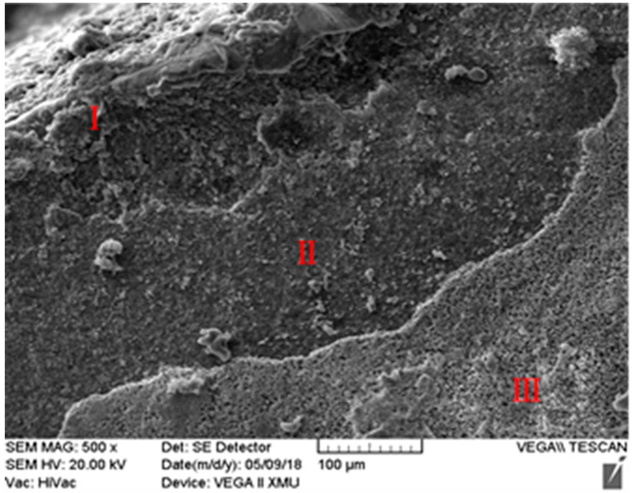
| Regions | O | Mg | Si | F | Cl | Ca |
|---|---|---|---|---|---|---|
| Region I | 47.08 | 30.15 | 5.72 | 7.05 | - | - |
| Region II | 60.47 | 25.42 | 2.37 | - | 0.73 | 2.57 |
| Region III | 71.34 | 0.61 | - | - | - | 22.09 |
© 2020 by the authors. Licensee MDPI, Basel, Switzerland. This article is an open access article distributed under the terms and conditions of the Creative Commons Attribution (CC BY) license (http://creativecommons.org/licenses/by/4.0/).
Share and Cite
Yao, Y.; Yang, W.; Liu, D.; Gao, W.; Chen, J. Preparation and Corrosion Behavior in Marine Environment of MAO Coatings on Magnesium Alloy. Materials 2020, 13, 345. https://doi.org/10.3390/ma13020345
Yao Y, Yang W, Liu D, Gao W, Chen J. Preparation and Corrosion Behavior in Marine Environment of MAO Coatings on Magnesium Alloy. Materials. 2020; 13(2):345. https://doi.org/10.3390/ma13020345
Chicago/Turabian StyleYao, Yuhong, Wei Yang, Dongjie Liu, Wei Gao, and Jian Chen. 2020. "Preparation and Corrosion Behavior in Marine Environment of MAO Coatings on Magnesium Alloy" Materials 13, no. 2: 345. https://doi.org/10.3390/ma13020345