Improvement of Adhesive Wear Behavior by Variable Heat Treatment of a Tool Steel for Sheet Metal Forming


Abstract
:1. Introduction
2. Materials and Methods
- When the number of experiments exceeds the available resources,
- When it is only required the information of the principal effects or the information provided by low order interactions of the factors,
- In exploratory studies where there are many factors,
- When the assumption is made that only a few effects are important.
- The Vickers hardness before nitriding. The applied load was of 294.2 N, while the value considered in each experiment was the average value obtained from 10 hardness indentations.
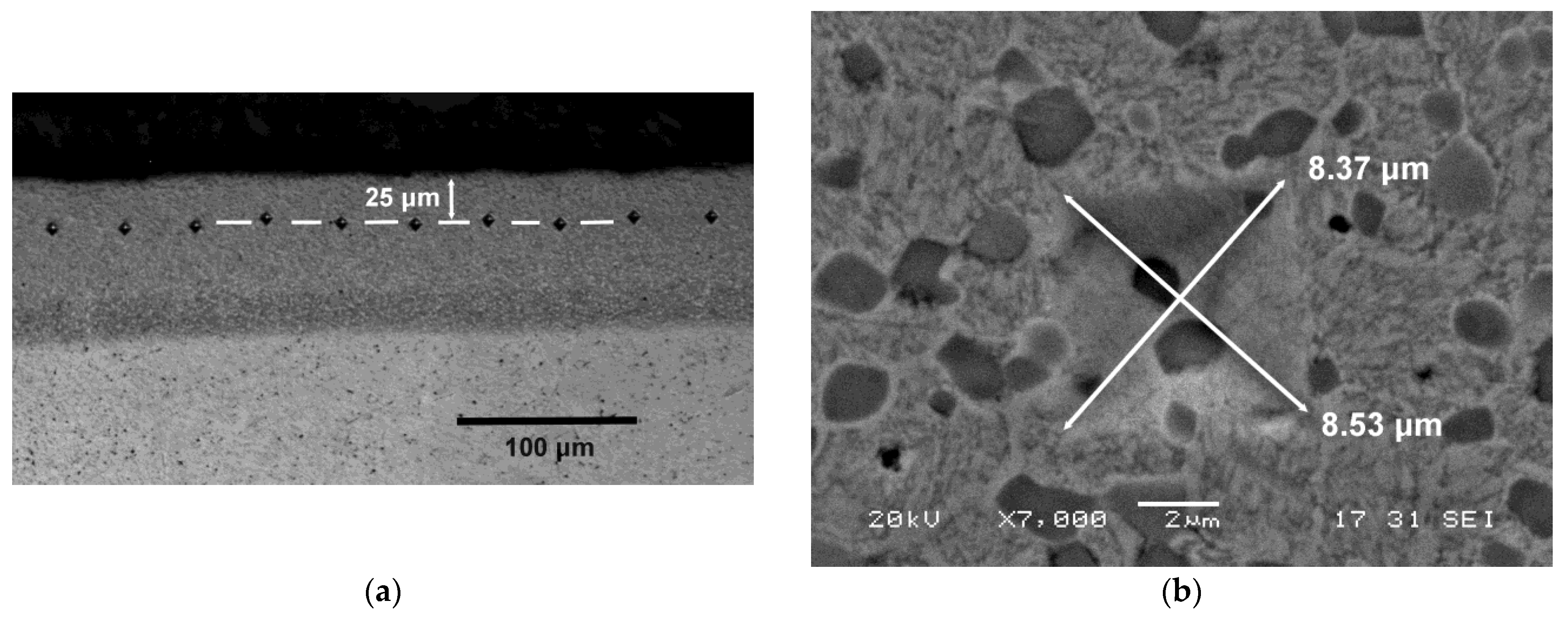
- The Vickers hardness of the nitrided layer in Experiments 5 to 8. The applied load was 0.5 N. The estimated hardness value was made to coincide with the average value obtained from the 20 indentations made at 25 μm from the outer face of the nitrided layer (see depiction in Figure 1).
- The adhesive wear resistance by means of the pin on disc test with a linear speed of 0.38 ms−1 and a load of 30 N. The pin corresponded with each of the 8 experiments. It had a circular cross-section of 3 mm in diameter. The disk was manufactured in steel manufactured in accordance with the DIN 42CrMo4 (AISI 4140) standard in the oil-quenched state. Its hardness at the time of the trials was 650 HV.
3. Results and Discussion
4. Conclusions
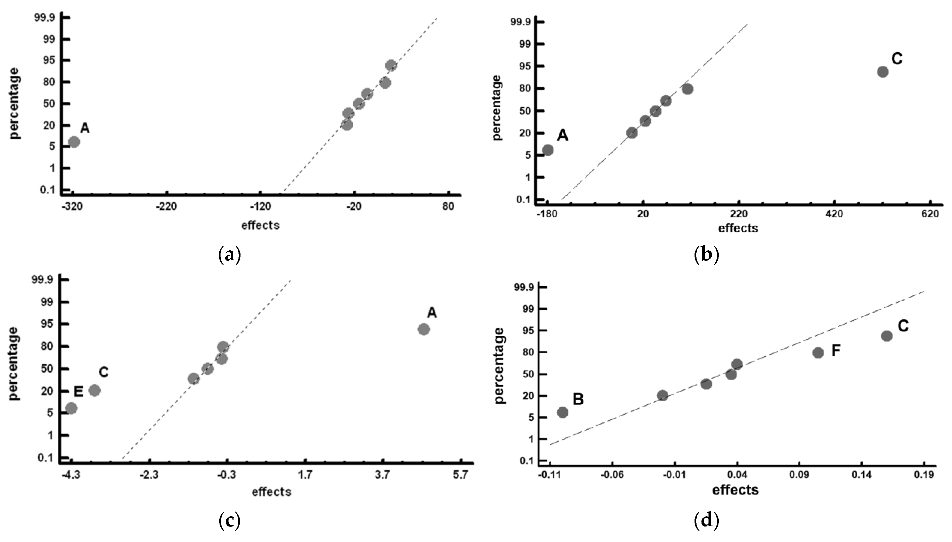
- The results show that the quench cooling medium after destabilization of austenite at 1100 °C seems not to have a significant influence on wear resistance. This allows manufacturers to quench tools in the air with the corresponding savings as well as to reduce the risk of quench cracking.
- In regards to the holding time at the destabilizing temperature of 1100 °C, it can be concluded that long holding times will not yield a significant effect on adhesive wear resistance.
- Our findings show that the most suitable tempering temperature should be 500 °C for optimum performance against adhesive wear.
- The analysis also shows that the best results are obtained when three tempering treatments of two h/each are conducted at 500 °C.
- The nitriding treatment produces an increase in the resulting hardness values comprised between 350 and 700 HV with regard to the samples without thermo chemical treatment.
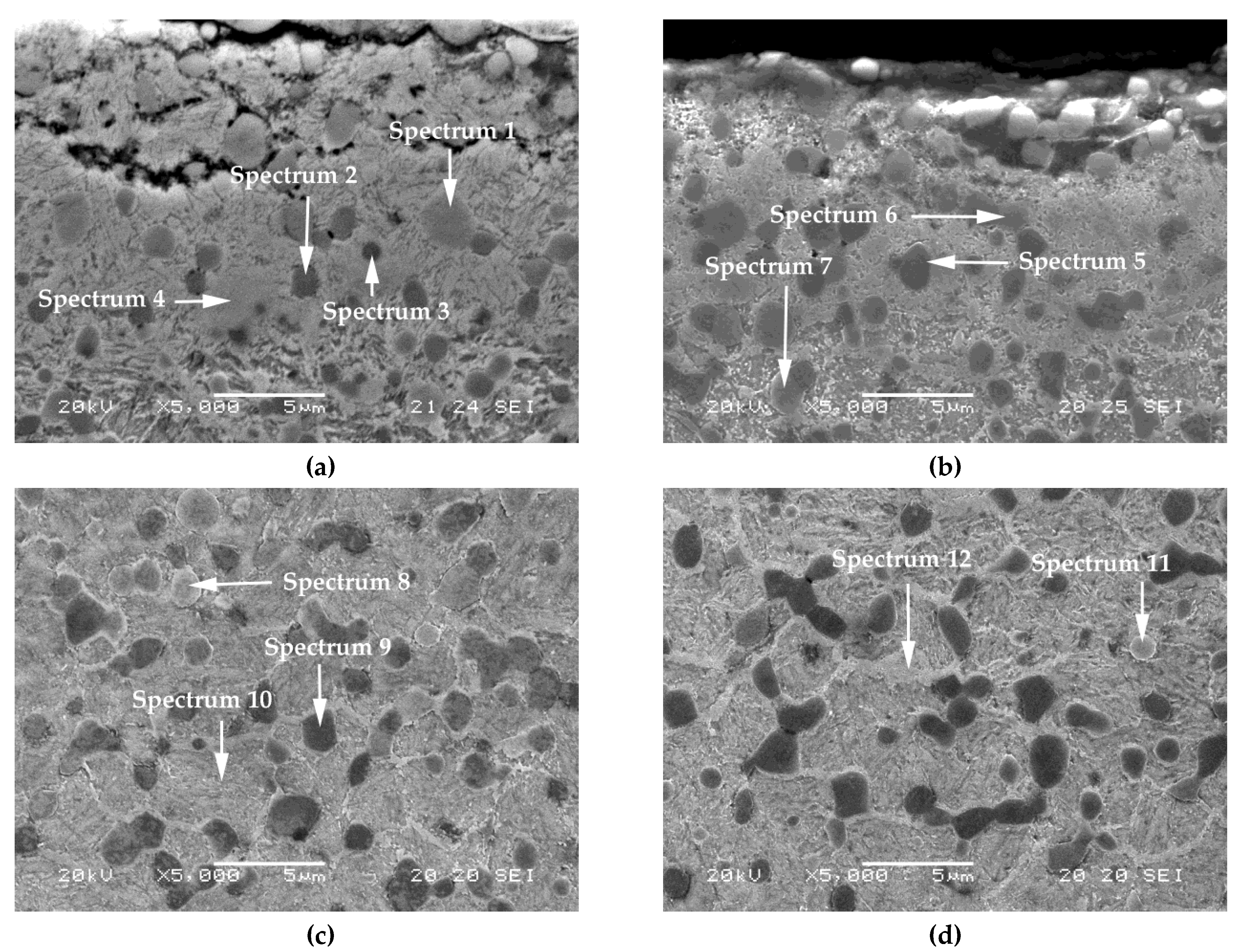
- Our observations show that the M7C3 carbides are transformed into carbonitrides during nitriding, with variable weight percentages of above 15 wt.%. However, MC carbides seemed not to be affected by this nitriding process. The weight percentage of N in the matrix constituent in the nitrided layer lies between five and eight wt.%.
Author Contributions
Funding
Conflicts of Interest
References
- Davis, J.R. Tool Materials; ASM International: Materials Park, OH, USA, 1995; pp. 14–16. [Google Scholar]
- Çelik, G.A.; Polat, Ş.; Atapek, H. Tribological behavior of CrN-coated Cr-Mo-V steels used as die materials. Int. J. Miner. Metall. Mater. 2017, 24, 1394–1402. [Google Scholar] [CrossRef]
- Gonzalez-Pociño, A.; Alvarez-Antolin, F.; Asensio-Lozano, J. Optimization of quenching and tempering parameters for the precipitation of M7C3 and MC secondary carbides and the removal of the austenite retained in Vanadis 10 tool steel. Metals 2019, 9, 627. [Google Scholar] [CrossRef]
- Bílek, P.; Sobotová, J.; Jurči, P. Evaluation of the microstructural changes in Cr-V ledeburitic tool steels depending on the Austenitization temperature. Mater. Tehnol. 2011, 45, 489–493. [Google Scholar]
- Pašák, M.; Čička, R.; Bílek, P.; Jurči, P.; Čaplovič, L. Study of phase transformations in Cr-V tool steel. Mater. Tehnol. 2014, 48, 693–696. [Google Scholar]
- Jurči, P.; Dománková, M.; Čaplovič, L.; Ptačinová, J.; Sobotová, J.; Salabová, P.; Prikner, O.; Šuštaršič, B.; Jenko, D. Microstructure and hardness of sub-zero treated and no tempered P/M Vanadis 6 ledeburitic tool steel. Vacuum 2015, 111, 92–101. [Google Scholar] [CrossRef]
- Powell, G.L.F.; Bee, J.V. Secondary carbide precipitation in an 18 wt.%Cr-1 wt.% Mo white iron. J. Mater. Sci. 1996, 31, 707–711. [Google Scholar] [CrossRef]
- Efremenko, V.; Shimizu, K.; Chabak, Y. Effect of destabilizing heat treatment on solid-state phase transformation in high-chromium cast irons. Metall. Mater. Trans. A 2013, 44, 5434–5446. [Google Scholar] [CrossRef]
- Hui, L.; Han-Guang, F.; Jiang, J.; Jun, W. Effect of heat treatment on microstructure and property of high vanadium wear-resistant alloy. Materwiss. Werksttech. 2018, 49, 1485–1493. [Google Scholar] [CrossRef]
- Jurči, P.; Dománková, M.; Ptačinová, J.; Pašák, M.; Kusý, M.; Priknerová, P. Investigation of the microstructural changes and hardness variations of sub-zero treated Cr-V ledeburitic tool steel due to the tempering treatment. J. Mater. Eng. Perform. 2018, 27, 1514–1529. [Google Scholar] [CrossRef]
- Zhou, H.; Wang, J.; Su, Y.; Lian, J.; Keisaku, Q. Heat treatment of high carbon vanadium high speed steel for roller. Kang T’ieh/Iron Steel 2000, 35, 47–50. [Google Scholar]
- Guerrero, M.P.; Flores, C.R.; Pérez, A.; Colás, R. Modelling heat transfer in hot rolling work rolls. J. Mater. Process. Technol. 1999, 94, 52–59. [Google Scholar] [CrossRef]
- Chang, D.F. Thermal stresses in work rolls during the rolling of metal strip. J. Mater. Process. Technol. 1999, 94, 45–51. [Google Scholar] [CrossRef]
- Stevens, P.G.; Ivens, K.P.; Harper, P. Increasing work- roll life by improved roll- cooling practice. J. Iron Steel Inst. 1971, 209, 1–11. [Google Scholar]
- Pauschitz, A.; Roy, M.; Franek, F. Mechanisms of sliding wear of metals and alloys at elevated temperatures. Tribol. Int. 2008, 41, 584–602. [Google Scholar] [CrossRef]
- Şelte, A.; Özkal, B.; Arslan, K.; Ülker, S.; Hatman, A. Effect of nitriding on the wear resistance of tool powder steels with different contents of V, Cr and Mo. Met. Sci. Heat Treat. 2018, 59, 729–734. [Google Scholar] [CrossRef]
- Pero-Sanz, J.A. Ciencia e Ingeniería de Materiales (Science and Engineering of Materials), 2nd ed.; Dossat: Madrid, Spain, 2006; pp. 329–330. [Google Scholar]
- Nordin, M.; Larsson, M.; Hogmark, S. Mechanical and tribological properties of multilayered PVD TiN/CrN. Wear 1999, 232, 221–225. [Google Scholar] [CrossRef]
- Zhou, Y.; Asaki, R.; Soe, W.H.; Yamamoto, R.; Chen, R.; Iwabuchi, A. Hardness anomaly, plastic deformation work and fretting wear properties of polycrystalline TiN/CrN multilayers. Wear 1999, 236, 159–164. [Google Scholar] [CrossRef]
- Yashar, P.; Barnett, S.A.; Rechner, J.; Sproul, W.D. Structure and mechanical properties of polycrystalline CrN/TiN superlattices. J. Vac. Sci. Technol. A 2002, 16, 2913–2918. [Google Scholar] [CrossRef]
- Taktak, S.; Gunes, I.; Ulker, S.; Yalcin, Y. Effect of N2 + H2 gas mixtures in plasma nitriding on tribological properties of duplex surface treated steels. Mater. Charact. 2008, 59, 1784–1791. [Google Scholar] [CrossRef]
- Prat-Bartés, A.; Tort-Martorell, X.; Grima-Cintas, P.; Pozueta-Fernández, L.; Solé-Vidal, I. Métodos Estadísticos (Statistical Methods), 2nd ed.; U.P.C: Barcelona, Spain, 1997; pp. 170–178. [Google Scholar]
- Pero-Sanz, J.A. Aceros (Steels); Dossat: Madrid, Spain, 2004; pp. 140–144. [Google Scholar]
- Davis, J.R. Carbon and Alloy Steels; ASM International: Materials Park, OH, USA, 1996; pp. 219–220. [Google Scholar]


| C | Si | Mn | Cr | Mo | V |
|---|---|---|---|---|---|
| 2.9 | 0.5 | 0.5 | 8 | 1.5 | 9.8 |
| Factors | Levels | |||
|---|---|---|---|---|
| Code | Description of The Factors | Units | −1 Level | +1 Level |
| A | Tempering temperature | °C | 500 | 600 |
| B | Holding time at 1100 °C | h | 4 | 8 |
| C | Nitriding | - | No | Yes |
| D | Quench cooling medium | - | air | oil |
| E | Number of temperings | - | 2 | 3 |
| F | Tempering time | h | 2 | 4 |
| No. | A | B | C | D | E | F | Restricted Confounding Pattern |
|---|---|---|---|---|---|---|---|
| 1 | −1 | −1 | −1 | +1 | +1 | +1 | A + BD + CE B + AD + CF C + AE + BF D + AB + EF E + AC + DF F + BC + DE AF + BE + CD |
| 2 | +1 | −1 | −1 | −1 | −1 | +1 | |
| 3 | –1 | +1 | −1 | −1 | +1 | −1 | |
| 4 | +1 | +1 | −1 | +1 | −1 | −1 | |
| 5 | −1 | −1 | +1 | +1 | −1 | −1 | |
| 6 | +1 | −1 | +1 | −1 | +1 | −1 | |
| 7 | −1 | +1 | +1 | −1 | −1 | +1 | |
| 8 | +1 | +1 | +1 | +1 | +1 | +1 |
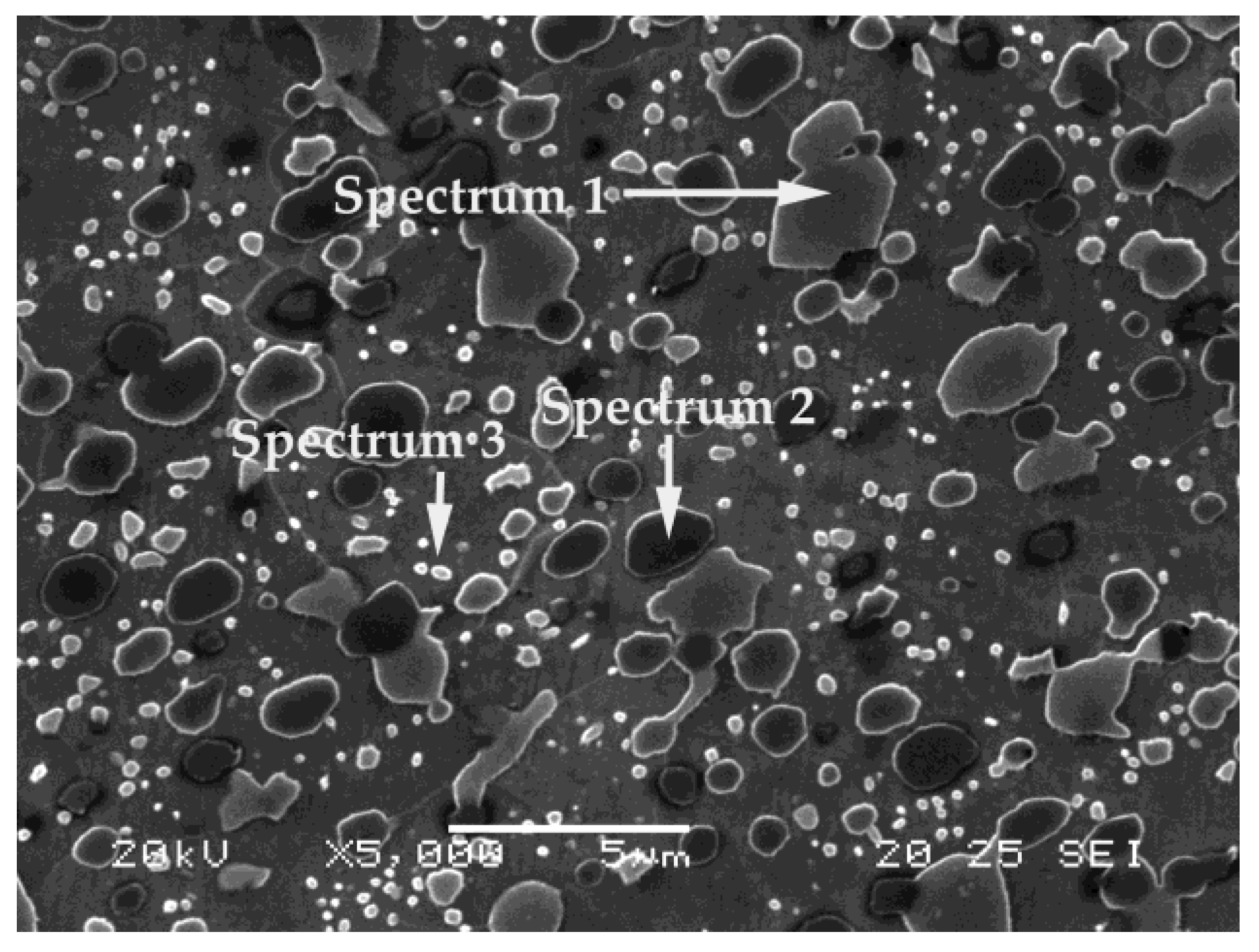
| Spectrum | %C | %V | %Cr | %Fe | %Mo | Most Likely Carbide Type |
|---|---|---|---|---|---|---|
| 1 | 67.1 | 4.38 | 15.01 | 13.11 | 0.40 | M7C3 |
| 2 | 62.29 | 20.19 | 4.60 | 11.93 | 0.98 | MC |
| 3 | 38.75 | 2.96 | 5.16 | 53.13 | - | M3C |
| (a) Hardness before nitriding. | ||||||
| Experiment | HV | Auxiliary Columns Corresponding to Yates’ Algorithm | Effects | |||
| I | II | III | ||||
| 1 | 824 1 | 1328 | 2614 | 5303 | 662.8 | Average |
| 2 | 504 1 | 1286 | 2689 | −1275 | −318.7 | A + BC + CE |
| 3 | 775 1 | 1379 | −584 | −111 | −27.7 | B + AD + CF |
| 4 | 511 1 | 1310 | −691 | 51 | 18.7 | C + AE + BF |
| 5 | 861 1 | −320 | −42 | 75 | 12.7 | D + AB + EF |
| 6 | 518 1 | −264 | −69 | −107 | −26.7 | E + AC + DF |
| 7 | 829 1 | −343 | 56 | −27 | −6.7 | F + BC + DE |
| 8 | 481 1 | −348 | −5 | −61 | −15.2 | AF + BE + CD |
| (b) Hardness after nitriding. | ||||||
| Experiment | HV | Auxiliary Columns Corresponding to Yates’ Algorithm | Effects | |||
| I | II | III | ||||
| 1 | 824 1 | 1328 | 2614 | 7309 | 913.5 | Average |
| 2 | 504 1 | 1286 | 4695 | −717 | −179.2 | A + BC + CE |
| 3 | 775 1 | 2234 | −584 | 185 | 46.4 | B + AD + CF |
| 4 | 511 1 | 2461 | −133 | 99 | 520 | C + AE + BF |
| 5 | 1161 2 | −320 | −42 | 2081 | 24.7 | D + AB + EF |
| 6 | 1073 2 | −264 | 227 | 451 | 112.7 | E + AC + DF |
| 7 | 1253 2 | −88 | 56 | 269 | 67.4 | F + BC + DE |
| 8 | 1208 2 | −45 | 43 | −13 | −3.3 | AF + BE + CD |
| (c) Pin-on-disc wear. | ||||||
| Experiment | Δm (mg) | Auxiliary Columns Corresponding to Yates’ Algorithm | Effects | |||
| I | II | III | ||||
| 1 | 2.4 | 13.5 | 25.5 | 36.2 | 4.52 | Average |
| 2 | 11.1 | 12 | 10.7 | 19 | 4.75 | A + BC + CE |
| 3 | 1.3 | 6.9 | 18.1 | −4.6 | 1.15 | B + AD + CF |
| 4 | 10.7 | 3.8 | 0.9 | −1.8 | −3.7 | C + AE + BF |
| 5 | 2.6 | 8.7 | −1.5 | −14.8 | −0.45 | D + AB + EF |
| 6 | 4.3 | 9.4 | −3.1 | −17.2 | −4.3 | E + AC + DF |
| 7 | 2.3 | 1.7 | 0.7 | −1.6 | −0.4 | F + BC + DE |
| 8 | 1.5 | −0.8 | −2.5 | −3.2 | −0.8 | AF + BE + CD |
| (d) Pin-on-disc wear. | ||||||
| Experiment | μ | Auxiliary Columns Corresponding to Yates’ Algorithm | Effects | |||
| I | II | III | ||||
| 1 | 0.77 | 1.51 | 2.61 | 5.86 | 0.732 | Average |
| 2 | 0.74 | 1.1 | 3.25 | 0.16 | 0.04 | A + BC + CE |
| 3 | 0.51 | 1.62 | 0.05 | −0.4 | −0.1 | B + AD + CF |
| 4 | 0.59 | 1.63 | 0.11 | 0.14 | 0.16 | C + AE + BF |
| 5 | 0.79 | −0.03 | −0.41 | 0.64 | 0.03 | D + AB + EF |
| 6 | 0.83 | 0.08 | 0.01 | 0.06 | 0.01 | E + AC + DF |
| 7 | 0.78 | 0.04 | 0.11 | 0.42 | 0.10 | F + BC + DE |
| 8 | 0.85 | 0.07 | 0.03 | −0.08 | −0.02 | AF + BE + CD |
| Spectrum | %C | %V | %Cr | %Fe | %Mo | %N |
|---|---|---|---|---|---|---|
| 1 | 10.76 | 9.81 | 27.88 | 29.76 | 2.21 | 19.59 |
| 2 | 18.24 | 39.76 | 7.48 | 30.56 | 3.97 | - |
| 3 | 14.28 | 38.52 | 6.93 | 35.04 | 5.23 | - |
| 4 | 11.98 | 1.80 | 5.88 | 71.59 | - | 8.75 |
| 5 | 24.50 | 46.05 | 6.37 | 18.55 | 4.53 | - |
| 6 | 13.41 | 9.93 | 23.51 | 30.94 | 1.35 | 20.87 |
| 7 | 16.18 | 7.39 | 17.17 | 40.67 | 1.30 | 17.30 |
| 8 | 9.22 | 9.03 | 32.97 | 30.55 | 2.40 | 15.84 |
| 9 | 32.40 | 29.56 | 6.25 | 28.60 | 3.19 | - |
| 10 | 6.63 | 2.86 | 6.96 | 77.71 | - | 5.84 |
| 11 | 11.41 | 9.4 | 30.56 | 29.66 | 2.34 | 14.63 |
| 12 | 24.42 | 2.27 | 6.42 | 60.77 | - | 6.12 |
© 2019 by the authors. Licensee MDPI, Basel, Switzerland. This article is an open access article distributed under the terms and conditions of the Creative Commons Attribution (CC BY) license (http://creativecommons.org/licenses/by/4.0/).
Share and Cite
Gonzalez-Pociño, A.; Alvarez-Antolin, F.; Asensio-Lozano, J. Improvement of Adhesive Wear Behavior by Variable Heat Treatment of a Tool Steel for Sheet Metal Forming. Materials 2019, 12, 2831. https://doi.org/10.3390/ma12172831
Gonzalez-Pociño A, Alvarez-Antolin F, Asensio-Lozano J. Improvement of Adhesive Wear Behavior by Variable Heat Treatment of a Tool Steel for Sheet Metal Forming. Materials. 2019; 12(17):2831. https://doi.org/10.3390/ma12172831
Chicago/Turabian StyleGonzalez-Pociño, Alejandro, Florentino Alvarez-Antolin, and Juan Asensio-Lozano. 2019. "Improvement of Adhesive Wear Behavior by Variable Heat Treatment of a Tool Steel for Sheet Metal Forming" Materials 12, no. 17: 2831. https://doi.org/10.3390/ma12172831