Article

Thermal Evolution of NiFe-NO3 LDH and Its Application in Energy Storage Systems

by
Marco Fortunato
1,
Andrea Pietro Reverberi
1,
Bruno Fabiano
2 and
Anna Maria Cardinale
1,*
1
Department of Chemistry and Industrial Chemistry, Università degli Studi di Genova, Via Dodecaneso 31, 16146 Genova, Italy
2
Department of Civil, Chemical and Environmental Engineering, Polytechnic School, Università degli Studi di Genova, Via Opera Pia 15, 16145 Genova, Italy
*
Author to whom correspondence should be addressed.
Energies 2024, 17(5), 1035; https://doi.org/10.3390/en17051035
Submission received: 29 January 2024 / Revised: 15 February 2024 / Accepted: 20 February 2024 / Published: 22 February 2024
(This article belongs to the Collection Renewable Energy and Energy Storage Systems)

Abstract

:
In this work, the performances of nickel iron layered double hydroxides (LDH) with the nitrate anion at the interlayer (NiFe-NO3) for the manufacture of anodes for lithium-ion batteries have been tested before and after its sintering at different temperatures. After synthesis, the material was thermally analyzed in a range 30–1250 °C, showing a mass loss occurring in three different consecutive steps leading to a total mass decrease of ~30 mass%. Following thermogravimetric analysis (TGA), four samples were prepared by annealing at four different temperatures: one of the four did not undergo a thermal treatment (NiFe-0), while the remaining three were annealed at 250 °C, 360 °C, and 560 °C for 6 h (NiFe-250, NiFe-360, and NiFe-560). All materials where completely characterized via FE-SEM, PXRD, and FT-IR. The pristine LDH material showed some structural and compositional changes for growing temperatures, starting from the typical turbostratic hexagonal structure through a mixture of amorphous metal oxides and finally to the stoichiometric oxides FeNi2O4 and NiO. The as-obtained materials were mixed with carbon black (C65) and sodium alginate and tested as electrodes in Swagelok half cells in LP30 vs. metallic Li to perform CV and GCPL analysis. The electrochemical tests showed that the performances of NiFe-0, both in terms of stability and specific capacity, are not so different from the one of the NiFe-560, even if the Ni mass% in the former is lower than in the NiFe-560. This phenomenon could be explained by assuming a combined mechanism of reaction involving both intercalation and conversion.

1. Introduction

The importance of energy storage to reach zero-net requirements and to reduce greenhouse gas emissions and minimize carbon footprints is a key aspect in current research [1] and in modern technology [2]. For this reason, the topic of energy storage has a highly interdisciplinary character, including pure chemistry [3], electrochemistry [4], material science [5], and safety science [6]. Energy storage refers to many sectors of engineering, like mechanical, chemical, and electrical engineering [7]. Intensive research in the latter field led to a refinement of propulsion systems based on electric traction, with inevitable repercussions on research about chemical energy storage systems in rechargeable electric accumulators [8]. On this theme, many choices are possible depending on the intended use and their practical disadvantages, which are typical of each kind of accumulator, often representing a limiting factor if not a crucial bottleneck [9]. In their recent review, Patel et al. [10] proposed a thorough discussion concerning all current types of lithium and non-lithium-based rechargeable battery systems (LIBs), enlightening a discrepancy between theoretical and practical problems affecting such energy storage methods [11].
A common point to most studies on LIBs is focused on the optimization of a set of parameters affecting the real utilization of rechargeable cells [12]. After the seminal paper of Goodenough and Park [13], who described the main figures of merit for a LIB, Deng [14] presented a very clear analysis concerning these aspects, surveying some basic physical “descriptors” having a very important role in the real world. Among them, the main role is played by the total charge per unit weight or volume, the specific energy per unit mass or volume, and the output power, expressed by the product of cell voltage V and discharge current intensity. The latter parameter is particularly crucial, being related to kinetic aspects that are often underestimated in literature, but there are exceptions [15]. In fact, as a general trend, literature tends to focus preferentially on thermodynamics aspects determining the electromotive force of the cell, resulting from voltages related to a combination of electrode reactions at an open circuit. For this reason, the specific structure and composition of each electrode has been the object of very wide investigations, with studies specifically focused on single anodes [16] or cathodes [17]. In the case of LIBs, the overall scheme generally relies upon Li+ ionic transfer in an electrolyte, where the discharge phase takes place by means of an anode subject to a delithiation process and a cathode where the reverse occurs. A common classification criterion for both anodes and cathodes stems in two different physicochemical operating principles, which can be essentially based on Li-ions intercalation, namely on Li-ions removal–insertion [18], or on Li-ion conversion–reaction, building new chemical bonds in the embedding substrate [19]. Manthiram [20] enlightened how such different mechanisms may have a basic role in affecting the charge-storage capacity, through triggering disadvantageous secondary phenomena, such as an excessive volume swelling for anodes or a dramatic life cycle reduction for cathodes, both in cases of conversion–reaction Li storage.
In its turn, the physicochemical properties of an electrolyte may represent an important rate limiting step of the whole process, even conditioning the choice of the relevant electrodes. As is well known, the need for higher cell voltages, in view of specific energy maximization, may actually prevent the use of an aqueous electrolyte by forcing the choice towards non-aqueous media, usually made of aprotic organic solvents [21]. Implicitly, this situation poses a typical problem of multi-constrained optimization [22].
Cathodes’ structure and composition in LIBs have been extensively surveyed in the recent review of Kotal et al. [23], starting from more conventional Li-based layered transition metal oxides, including polyanion compounds, up to the most recent conversion-type cathodes and finally to organic cathodes [24]. In the former case, the cathodic lithiation/delithiation processes, occurring during charge/discharge, can be concisely described as follows:
Li(1−x)MeyOz + x Li+ + x e−1 ↔ LiMeyOz
where Me indicates a transition metal, usually consisting of Co, Ni, and Mn, or a combination of them [25]. Among these elements, the most suitable choice for a cathode configuration depends on a trade-off between advantages related to a gain in charge capacity and drawbacks connected with the onset of unwanted phase transitions during cycling and a tendency to oxidize organic electrolytes, particularly pronounced for metal Ni [20].
Anodes underwent a parallel evolution trend, where the use of Li metal, particularly interesting for its high charge capacity (3.86 Ah/g) and low reduction potential (−3.04 V), was replaced by other formulations for safety issues and technical drawbacks related to dendrite formation on the anode surface [26]. Composite materials, which have proven to offer appealing performances in many different applications [27], represent a cornerstone for LIB anodes operating by a Li-ion intercalation process, despite graphite suffering from an upper stoichiometrical limit in its charge-storage capacity according to the following scheme [28]:
LiC6 ↔ 6C + Li+ + e−1
As an alternative to the aforementioned intercalation processes, Li anodes relying upon conversion–reaction schemes, such as SnO2 and transition metals oxides/sulphides, have been investigated [29].
Layered double hydroxides (LDH), owing to their intrinsic turbostratic structure capable of accepting intercalating ions, have been advantageously adopted as green photocatalysts [30] and selective sorbents for environmental decontamination [31]. To the best of our knowledge, only one study concerning the use of LDHs as a new intercalating Li ion substrate for the realization of LIB anodes has been proposed in literature [32]. In an effort to cover this gap, the present study is focused on the use of a NiFe LDH intercalated by a nitrate anion, exploring the possibility of using it as a promising substrate for Li+ anodic storage. Essentially, the novelty and potential implications of this research consists of finding the best trade-off between a satisfactory energy storage capacity and a compliance with the paradigms of green synthesis for environmental protection [33]. It is shown that the presence of a bidimensional structure promotes the stabilization of the anode, leading to high performances with a lower amount of the electrochemically active Ni, a usually noxious cation for living organisms. Additionally, as reported in [34], notable challenges to obtain a more sustainable process industry in view of climate change and energy transition are related to developing new and safer energy storage devices and, in particular battery materials, taking into proper account at the design stage relevant novel hazards, safety measures, and risk management. In this regard, it is worth noting that even though the energy density increases as the nickel content increases, the thermal and structural stability decreases significantly under abnormal circumstances [35].
The paper is structured as follows. In Section 2, the chemical species used for the synthesis of the LDH are described, together with the corresponding experimental procedure and the apparatuses adopted to characterize the relevant materials. In Section 3, the characterization of the materials and their response in electrochemical tests is made, and finally in Section 4, the conclusions are drawn and an outlook on a possible future development of the present study is proposed.

2. Materials and Methods

2.1. Reagents Used for LDH Synthesis and Electrochemical Cell Setup

The chemicals used in the present experimental tests, along with their purity and supplier company, have been reported in Table 1.
Deionized water was used in all the experimental tests, produced by an ion exchange unit (M3/M6 Chemical Bürger s.a.s, Genova, Italy). Prior to use, it was also boiled and bubbled with argon to completely remove CO2, since in the synthesis condition, it could lead to the formation of a carbonate anion, which is one of the most akin anions for the interlayer.

2.2. Synthesis Method

Achieving the desired LDH stoichiometry and morphology, depending on the intended usage, primarily relies on finding the correct combination of various factors. These factors include synthesis procedures, reaction pH, reagent types, solvents, temperature, and reaction duration. NiFe-NO3 LDH, more precisely identified as [ Ni 0.66 2 + Fe 0 . 33 3 + ( OH ) 2 ] 0.33 + ( NO 3 ) 0.33 , was synthesized following the high supersaturation pathway proposed by Grégoire et al. [36]. Namely, a mixed solution of Ni and Fe salts in the due proportion was titrated with a 0.5 M solution of NaOH, in an inert atmosphere. The obtained solid precursor was set to rest with its mother liquor in a closed bottle under argon for 3 days at 70 °C. Afterwards, the compound was filtered, washed several times with deionized water, and dried. Four aliquots of the compound were considered in the present experimental campaign. One of them, here named as NiFe-0, did not undergo any thermal treatment, while the remaining three, here named as NiFe-250, NiFe-360, and NiFe-560, were annealed in an oven (Carbolite elf 11/6B) for 4 h at 250 °C, 360 °C, and 560 °C, respectively.

2.3. Characterization Setup

The materials were characterized by means of different techniques, here listed as follows:
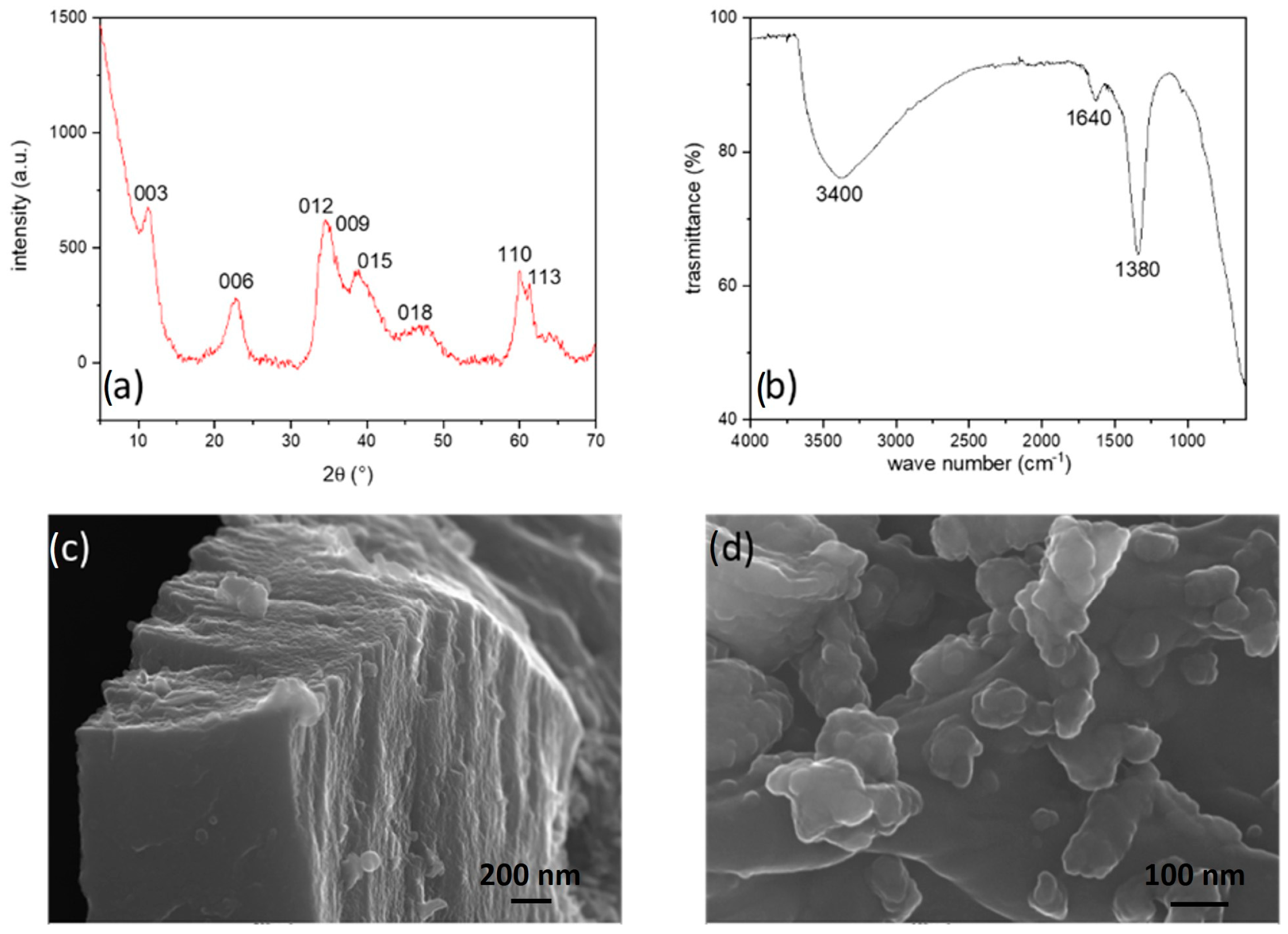
  • Powder X-ray diffraction (PXRD): the patterns were recorded using a powder diffractometer (X’Pert MPD, Philips, Almelo, The Netherlands) equipped with a Cu anticathode (Kα1Cu = 1.5406 Å). The data were collected between 10 and 90 2ϑ with a step of 0.001 and a measuring time of 50 s/step. The indexing of the diffraction data was performed in comparison with the literature using the software package [WinPLOT version 2019].
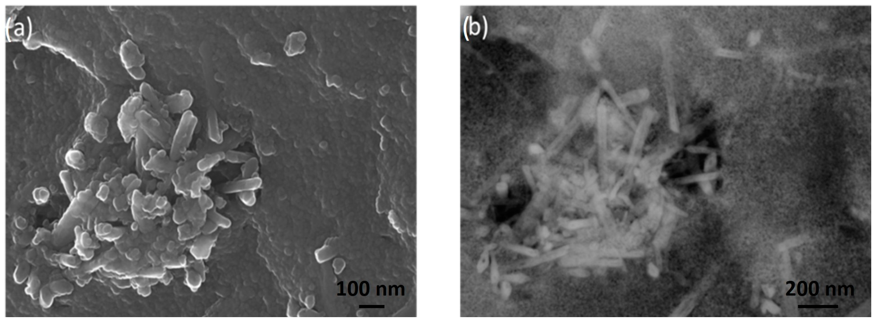
  • Field Emission Scanning Electron Microscopy (FE-SEM): the samples were observed with a ZEISS SUPRA 40 V microscope, applying an acceleration voltage of 5 kV for 50 s.
  • Fourier Transformed Infra-Red (FT-IR) spectroscopy: the spectra ranging from 4000 to 600 cm−1 were obtained utilizing a Spectrum 65 FT-IR Spectrometer (PerkinElmer, Waltham, MA, USA). The instrument was equipped with a KBr beam-splitter and a DTGS detector, and an ATR accessory with a diamond crystal was employed for data collection.
  • Inductively coupled plasma optical emission spectroscopy (ICP-OES): The experiments were conducted utilizing a Varian Vista PRO (Springvale, Australia) with an axially oriented configuration. The sample introduction setup included a pneumatic nebulizer of the glass concentric K-style type (Varian) connected to a glass cyclonic spray chamber (Varian).
  • Thermogravimetry Differential Thermal Analysis (TG-DTA): the analyses were conducted using a LabsysEvo 1600–Setaram thermobalance equipped with a double thermocouple Platinum/Platinum–Rhodium 10%. The thermocouples were calibrated by using, as calibration materials, high-purity elements such as Ag, Au. Approximately 20 mg of the sample was loaded into an open alumina crucible and subjected to heating from 30 °C to 1250 °C at a rate of 10 °C/min, under argon flow (60 mL/min). In the temperature range considered, the error on mass loss determination was 0.2% and in temperature determination 0.5%.

2.4. Cell Preparation for Electrochemical Tests

This section shows the steps by which the source material is transformed to be assembled in the electrode. An amount of 70% NiFe-LDH was crushed in a quartz mortar for 10 min with 20% of conductive carbon. Afterwards, 10% of sodium alginate in a water/isopropanol (9:1) solution was added to the mixture as binder. A 150 μm layer of the as-obtained ink was then coated on a 10 μm thick copper foil current collector, further dried in oven at 80 °C overnight, and finally cut in discs of 12 mm diameter. Each disc was then pressed by 8 tons, dried under vacuum at 120 °C, and stored in a glovebox. The same procedure was performed for NiFe-250, NiFe-320, and NiFe-560.
Sodium alginate, although not a conventional binder, proved to be very suitable for LDHs as it forms hydrogen bonds with hydroxyl groups of LDH, preventing undesired pealing, electrode cracking, and making the active substrate more resistant to discharge/charge cycles [32]. Additionally, it is worth noting that sodium alginate is a natural polymer which can be synthesized in aqueous solution without using any other noxious solvent, making it more sustainable than the standard battery binder polyvinylidene fluoride (PVDF).
The electrodes were then tested in a Swagelok® T-Cell, according to a standard procedure [37]. Analogous three-electrode setups have been adopted in other previous studies, though with slightly different cell configurations [38]. In this preliminary study, the experiments were carried out in a half-cell configuration to obtain all the possible information on the anodes in the best condition. The cell was assembled in an argon-filled glovebox and consisted of the previously prepared electrode as a working electrode, a metallic lithium counter electrode, and a metallic needle of lithium as a reference electrode, whose housings were separated by a glass fiber partition (Whatman grade GF/D). The commercial LP30 (1 M LiPF6 in ethylene carbonate/dimethyl carbonate in a weight ratio of 1:1) was chosen as an electrolyte. A schematic view of the electrochemical cell is reported in Figure 1. All tests were performed in the potential range 0.01–3 V vs. Li/Li+ in a binder climate chamber at 25 °C by means of a multichannel potentiostat (VMP3, Bio-Logic). The presently adopted experimental technique relied upon cyclic voltammetry (CV) at different scan rates increasing from 0.1 mV/s to 10 mV/s in galvanostatic cycling with potential limitation (GCPL) at a current applied of 50 mA/g.

3. Results and Discussion

NiFe-NO3 LDH underwent characterization, and the ICP-OES analysis verified a metals ratio of 2:1, as illustrated in Table 2.
The FT-IR spectrum, reported in Figure 2b, exhibits minimal signals. The prominent and broad band centred at 3400 cm−1 originates from the partial overlapping of the O–H stretching of hydroxides (usually at 3300 cm−1) and of the intercalated water molecules (at about 2850 cm−1). Additionally, a moderately intense signal at 1640 cm−1 corresponds to the bending mode of water, while the narrow band at 1380 cm−1 is associated with the ν3 vibration of nitrate [32], confirming the presence of nitrate anion in the interlayer.
The diffraction pattern of NiFe-NO3, illustrated in Figure 2a, confirms the typical hexagonal layered double hydroxide (LDH) structure (space group R −3 m) [39]. The calculated cell parameters using the WinPLOTR suite [40] are: a = 3.0(8) Å and c = 23.4(9) Å. The broad reflections indicate a small crystallite size and low crystallinity, with symmetric peaks corresponding to basal reflections d003, d006, d009, d110, d113, and asymmetric peaks related to the reflections d012, d015, d018 [36,39,41,42,43]. The presence of asymmetric peaks suggests a turbostratic nature, with different basal planes misaligned, as observed in low-magnification FE-SEM images (Figure 2c). Further examination at high magnification (Figure 2d) reveals the nanostructuring of the material surface.
A TG-DTA analysis conducted in the temperature range of 30 to 1250 °C reveals three main mass losses (Figure 3a). The first mass loss occurs between 30 and 250 °C, resulting in a 14% decrease in mass, attributed to the elimination of crystallization water and subsequent disordering of the layered structure. Subsequently, between 250 and 360 °C, there is a 10% mass loss, followed by a final 7% mass decrease from 360 to 500 °C. These latter two mass changes are likely associated with the dihydroxylation of LDH and degradation of interlayered nitrate. Between 500 °C and 560 °C, an exothermic process is evident in the DTA curve, indicative of recrystallization despite no observable mass change. To validate these hypotheses, three distinct samples, NiFe-250, NiFe-360, and NiFe-560, were prepared by annealing the initial material at temperatures of 250, 360, and 560 °C, respectively, based on the TG data. These samples were subjected to characterization through PXRD and FE-SEM. In Figure 3b, the diffraction patterns of the annealed samples and the pristine LDH are compared: NiFe-250 exhibits a structure resembling the initial LDH, but with reflections enlarged and reduced as intensity, suggesting an increasing disorder.
In the NiFe-360 °C, all previously observed peaks vanish, and the pattern results in a few prominent signals indicative of a blend of disordered Ni and Fe oxides. In the case of NiFe-560, different distinct and intense peaks emerge, which can be attributed to the cubic phases Fe2NiO4 (spinel-like) and NiO. This phenomenon is also evident in Figure 4, where the FE-SEM image of NiFe-560 reveals the presence of needle-shaped crystals, characteristic of spinels. The whole process occurring under heating could be resumed as follows:
[ ( N i 0.66 2 + F e 0.33 3 + O H 2 ] 0.33 + [ ( N O 3 ) 0.33 ] 0.33 · n H 2 O   [ ( N i 0.66 2 + F e 0.33 3 + O H 2 ] 0.33 + [ ( N O 3 ) 0.33 ] 0.33 + n H 2 O g a s
[ ( N i 0.66 2 + F e 0.33 3 + O H 2 ] 0.33 + [ ( N O 3 ) 0.33 ] 0.33 H 2 O g a s + O 2 g a s + N O 2 g a s + F e 2 O 3 + NiO
F e 2 O 3 + N i O F e 2 N i O 4
The pristine material (FeNi-0) and all the calcinated samples were prepared as electrodes and tested in a lithium half cell as described in Section 2.4.
In all four samples (Figure 5), the CV plot exhibits a distinct pattern for the first cycle compared to the subsequent ones. This disparity may arise from irreversible reactions leading to the activation of the material and the formation of the solid electrolyte interface (SEI). Shared peaks are observed across all electrodes: during lithiation, a small and broad peak around 1.5 V and a deeper one at 0.6 V are detected, while during delithiation, common peaks are located at 1.7 V and 2.5 V. In the untreated sample (NiFe-0), as depicted in Figure 5a), an additional peak appears during lithiation at 1 V and during delithiation at 1.1 V. These two peaks persist, albeit with decreasing intensity, from NiFe-250 (Figure 5b) to NiFe-360 (Figure 5c) and completely disappear in NiFe-560 (Figure 5d). Subsequent cycles for all samples display a sharp peak during lithiation at 0.9 V and during delithiation at 1.7 V and 2.5 V. NiFe-0 exhibits additional peaks during lithiation at 1.6 V and 0.5 V and during delithiation at 1.1 V. Although these peaks are retained in the other samples, their intensity diminishes with increasing temperature until they vanish entirely in NiFe-560.
The commonly observed peaks, as extensively documented in the literature [39,44,45], are attributed to the conversion reaction of Ni. Conversely, the additional peaks appear to be associated with reactions occurring at the interlayer, such as intercalation, given that their intensity diminishes as the layered structure decreases. The GCPL plot (Figure 6) reveals a considerable irreversible capacity loss in all samples, approximately 30% of the initial capacity. The curve shape is consistent across all samples; during discharge, there is a prolonged and tilted plateau around 1 V, succeeded by a more inclined one starting at approximately 0.5 V. In NiFe-pristine, an additional tilted plateau at around 1.6 V is evident, and its length decreases in the other samples with increasing calcination temperature. These findings align with the observations from the earlier CV analysis.
Observing the cyclic stability plot (Figure 7a), one can deduce that NiFe-pristine requires several cycles to stabilize, retaining approximately 30% of its initial capacity while delivering around 600 mAh/g. Both NiFe-250 and NiFe-320 exhibit poor stability; the former shows a continuous linear decline in capacity, and the latter experiences a rapid drop, with both retaining only 4% of their initial capacity after 40 cycles. On the other hand, NiFe-560 proves to be the most stable compound. After an initial capacity decrease, the material stabilizes at around 50% of the initial capacity, delivering 750 mAh/g after 40 cycles. The coulombic efficiency plot (Figure 7b) corroborates this trend: NiFe-0 stabilizes after a few cycles, and NiFe-560 achieves near-immediate stabilization, maintaining an efficiency value of about 98%. In contrast, the other two samples exhibit erratic behavior with a significant reduction in capacity values, falling below 75%. These results are intriguing, considering that the final specific capacity of NiFe-0 is not significantly different from that of NiFe-560, which is predominantly composed of NiO, a material well-documented in the literature for its applicability in LIBs [44,46]. Moreover, NiFe-560 contains only a quarter of the nickel mass compared to NiFe-0. This observation suggests a potential dual mechanism involving both conversion and intercalation reactions. However, further analyses are required to substantiate this conclusion.

4. Conclusions

In this study, the performances of a NiFe-NO3 electrode have been investigated in view of possible applications in LIBs. A combined analysis, incorporating thermal studies and electrochemical tests, revealed the influence of a layered double hydroxide (LDH) structure on electrochemical performance. The study suggested the onset of reversible reactions at 1.6 V during discharge and 1.1 V during recharge, gradually diminishing with the reduction of the material’s dimensionality. The pristine material, NiFe-NO3, exhibited a remarkably high initial capacity of 2200 mAh/g. However, it experienced a significant irreversible capacity loss (ICL), retaining only 30% of its initial capacity in the second cycle. Subsequently, the material stabilized over a few charge/discharge cycles, delivering more than 500 mAh/g even after 50 cycles. Although this value is lower, it remains comparable to NiO-based electrodes for LIBs (ranging between 400 and 1000 mAh/g) [44]. However, when considering the mass percentage of Ni in the two compounds, the ranking is reversed. NiFe-NO3 LDH contains only 22 mass% of Ni, whereas in NiO, the Ni content is approximately 80 mass%. Nickel is a critical raw material, and reducing its amount, without significantly compromising electrode performance, aligns with the goal of achieving more sustainable and economical batteries, possibly characterized by higher thermal and structural stability, in compliance with the Sustainable Development Goals of the United Nations 2030 Agenda (particularly the n. 7 affordable and clean energy).

Author Contributions

Conceptualization, A.M.C. and M.F.; methodology, M.F.; software, A.M.C. and B.F.; validation, M.F., A.P.R. and A.M.C.; formal analysis, M.F. and A.P.R.; investigation, M.F. and A.M.C.; resources, A.M.C.; data curation, M.F., A.M.C. and A.P.R.; writing—original draft preparation, M.F., A.P.R. and A.M.C.; writing—review and editing, M.F., A.M.C., A.P.R. and B.F.; visualization, A.M.C.; supervision, A.M.C., project administration, A.M.C. and M.F.; funding acquisition, A.M.C. All authors have read and agreed to the published version of the manuscript.

Funding

This research received no external funding.

Data Availability Statement

Data are contained within the article.

Conflicts of Interest

The authors declare no conflicts of interest.

References

  1. Chavan, S.; Rudrapati, R.; Manickam, S. A comprenhensive review on current advances of thermal energy storage and its applications. Alex. Eng. J. 2022, 61, 5455–5463. [Google Scholar] [CrossRef]
  2. Hörbe Emanuelsson, A.; Johnsson, F. The cost to consumers of carbon capture and storage—A product value chain analysis. Energies 2023, 16, 7113. [Google Scholar] [CrossRef]
  3. Tawalbeh, M.; Murtaza, S.Z.M.; Al-Othman, A.; Alami, A.H.; Singh, K.; Olabi, A.G. Ammonia: A versatile candidate for the use in energy storage systems. Renew. Energy 2022, 194, 955–977. [Google Scholar] [CrossRef]
  4. Navarro-Suárez, A.M.; Shaffer, M.S.P. Designing structural electrochemical energy storage systems: A perspective on the role of device chemistry. Front. Chem. 2021, 9, 810781. [Google Scholar] [CrossRef] [PubMed]
  5. Chang, C.; Chen, W.; Chen, Y.; Chen, Y.; Chen, Y.; Ding, F.; Fan, C.; Fan, H.J.; Fan, Z.; Gong, C.; et al. Recent Progress on Two-Dimensional Materials. Acta Phys. -Chim. Sin. 2021, 37, 2108017. [Google Scholar] [CrossRef]
  6. Vairo, T.; Pettinato, M.; Reverberi, A.P.; Milazzo, M.F.; Fabiano, B. An approach towards the implementation of a reliable resilience model based on machine learning. Process Saf. Environ. Prot. 2023, 172, 632–641. [Google Scholar] [CrossRef]
  7. Deepak Selvakumar, R.; Wu, J.; Ding, Y.; Alkaabi, A.K. Melting behavior of an organic phase change material in a square thermal energy storage capsule with an array of wire electrodes. Appl. Therm. Eng. 2023, 228, 120492. [Google Scholar] [CrossRef]
  8. Ding, Y.; Cano, Z.P.; Yu, A.; Lu, J.; Chen, Z. Automotive Li-ion batteries: Current status and future perspectives. Electrochem. Energy Rev. 2019, 2, 1–28. [Google Scholar] [CrossRef]
  9. Sarmah, S.; Lakhanlal; Kakati, B.K.; Deka, D. Recent advancement in rechargeable battery technologies. Wiley Interdiscip. Rev. Energy Environ. 2023, 12, e461. [Google Scholar] [CrossRef]
  10. Patel, M.; Mishra, K.; Banerjee, R.; Chaudhari, J.; Kanchan, D.K.; Kumar, D. Fundamentals, recent developments and prospects of lithium and non-lithium electrochemical rechargeable battery systems. J. Energy Chem. 2023, 81, 221–259. [Google Scholar] [CrossRef]
  11. Bubulinca, C.; Kazantseva, N.E.; Pechancova, V.; Joseph, N.; Fei, H.; Venher, M.; Ivanichenko, A.; Saha, P. Development of all solid-state Li-ion batteries: From key technical areas to commercial use. Batteries 2023, 9, 157. [Google Scholar] [CrossRef]
  12. Wu, F.; Maier, J.; Yu, Y. Guidelines and trends for next-generation rechargeable lithium and lithium-ion batteries. Chem. Soc. Rev. 2020, 49, 1569–1614. [Google Scholar] [CrossRef]
  13. Goodenough, J.B.; Park, K.-S. The Li-ion rechargeable battery: A perspective. J. Am. Chem. Soc. 2013, 135, 1167–1176. [Google Scholar] [CrossRef]
  14. Deng, D. Li-ion batteries: Basics, progress, and challenges. Energy Sci. Eng. 2015, 3, 385–418. [Google Scholar] [CrossRef]
  15. Kondo, Y.; Abe, T.; Yamada, Y. Kinetics of interfacial ion transfer in lithium-ion batteries: Mechanism understanding and improvement strategies. ACS Appl. Mater. Interfaces 2022, 14, 22706–22718. [Google Scholar] [CrossRef] [PubMed]
  16. Tirado, J.L. Inorganic materials for the negative electrode of lithium-ion batteries: State of the art and future prospects. Mater. Sci. Eng. 2003, R40, 103–136. [Google Scholar] [CrossRef]
  17. Nwachukwu, I.M.; Chinwe Nwanya, A.; Ekwealor, A.B.C.; Ezema, F.I. Recent progress in Mn and Fe-rich cathode materials used in Li-ion batteries. J. Energy Storage 2022, 54, 105248. [Google Scholar] [CrossRef]
  18. Scrosati, B.; Garche, J. Lithium batteries: Status, prospects and future. J. Power Sources 2010, 195, 2419–2430. [Google Scholar] [CrossRef]
  19. Wu, F.; Yushin, G. Conversion cathodes for rechargeable lithium and lithium-ion batteries. Energy Environ. Sci. 2017, 10, 435–459. [Google Scholar] [CrossRef]
  20. Manthiram, A. An outlook on lithium battery technology. ACS Cent. Sci. 2017, 3, 1063–1069. [Google Scholar] [CrossRef]
  21. Zhang, J.-G.; Xu, W.; Xiao, J.; Cao, X.; Liu, J. Lithium metal anodes with nonaqueous electrolytes. Chem. Rev. 2020, 120, 13312–13348. [Google Scholar] [CrossRef]
  22. Cai, X.; Zhang, C.; Zhang, L.; Zhang, W.; Gao, L. Comparative study on state of power estimation of lithium-ion battery based on equivalent circuit model. Jixie Gongcheng Xuebao/J. Mech. Eng. 2021, 57, 64–76. [Google Scholar] [CrossRef]
  23. Kotal, M.; Jakhar, S.; Roy, S.; Sharma, H.K. Cathode materials for rechargeable lithium batteries: Recent progress and future prospects. J. Energy Storage 2022, 47, 103534. [Google Scholar] [CrossRef]
  24. Shea, J.J.; Luo, C. Organic electrode materials for metal ion batteries. ACS Appl. Mater. Interfaces 2020, 12, 5361–5380. [Google Scholar] [CrossRef]
  25. Daniel, C.; Mohanty, D.; Li, J.; Wood, D.L. Cathode materials review. Review on Electrochemical Storage Materials and Technology: Proceedings of the 1st International Freiberg Conference on Electrochemical Storage Materials. Proc. AIP Conf. Proc. 2014, 1597, 26–43. [Google Scholar] [CrossRef]
  26. Mishra, A.; Mehta, A.; Basu, S.; Malode, S.J.; Shetti, N.P.; Shukla, S.S.; Nadagouda, M.N.; Aminabhavi, T.M. Electrode materials for lithium-ion batteries. Mater. Sci. Energy Technol. 2018, 1, 182–187. [Google Scholar] [CrossRef]
  27. Pascariu, V.; Avadanei, O.; Gasner, P.; Stoica, I.; Reverberi, A.P.; Mitoseriu, L. Preparation and characterization of PbTiO 3-epoxy resin compositionally graded thick films. Phase Transit. 2013, 86, 715–725. [Google Scholar] [CrossRef]
  28. Li, Y.; Lu, Y.; Adelhelm, P.; Titirici, M.-M.; Hu, Y.-S. Intercalation chemistry of graphite: Alkali metal ions and beyond. Chem. Soc. Rev. 2019, 48, 4655–4687. [Google Scholar] [CrossRef]
  29. Kim, H.-J.; Krishna, T.N.V.; Zeb, K.; Rajangam, V.; Muralee Gopi, C.V.V.; Sambasivam, S.; Raghavendra, K.V.G.; Obaidat, I.M. A comprehensive review of Li-ion battery materials and their recycling techniques. Electronics 2020, 9, 1161. [Google Scholar] [CrossRef]
  30. Cardinale, A.M.; Alberti, S.; Reverberi, A.P.; Catauro, M.; Ghibaudo, N.; Fortunato, M. Antibacterial and photocatalytic activities of LDH-based sorbents of different compositions. Microorganisms 2023, 11, 1045. [Google Scholar] [CrossRef]
  31. Cardinale, A.M.; Carbone, C.; Fortunato, M.; Fabiano, B.; Reverberi, A.P. ZnAl-SO4 layered double hydroxide and allophane for Cr(VI), Cu(II) and Fe(III) adsorption in wastewater: Structure comparison and synergistic effects. Materials 2022, 15, 6887. [Google Scholar] [CrossRef]
  32. Li, X.; Fortunato, M.; Cardinale, A.M.; Sarapulova, A.; Njel, C.; Dsoke, S. Electrochemical study on nickel aluminum layered double hydroxides as high-performance electrode material for lithium-ion batteries based on sodium alginate binder. J. Solid State Electrochem. 2022, 26, 49–61. [Google Scholar] [CrossRef]
  33. Reverberi, A.P.; Vocciante, M.; Salerno, M.; Ferretti, M.; Fabiano, B. Green synthesis of silver nanoparticles by low-energy wet bead milling of metal spheres. Materials 2020, 13, 63. [Google Scholar] [CrossRef]
  34. Pasman, H.; Sripaul, E.; Khan, F.; Fabiano, B. Energy transition technology comes with new process safety challenges and risks. Process Saf. Environ. Prot. 2023, 177, 765–794. [Google Scholar] [CrossRef]
  35. Zhang, S.S. Problems and their origins of Ni-rich layered oxide cathode materials. Energy Storage Mater. 2020, 24, 247–254. [Google Scholar] [CrossRef]
  36. Grégoire, B.; Ruby, C.; Carteret, C. Hydrolysis of mixed Ni2+–Fe3+ and Mg2+–Fe3+ solutions and mechanism of formation of layered double hydroxides. J. Chem. Soc. Dalton Trans. 2013, 42, 15687–15698. [Google Scholar] [CrossRef]
  37. Solchenbach, S.; Pritzl, D.; Kong, E.J.Y.; Landesfeind, J.; Gasteiger, H.A. A gold micro-reference electrode for impedance and potential measurements in lithium ion batteries. J. Electrochem. Soc. 2016, 163, A2265–A2272. [Google Scholar] [CrossRef]
  38. Ender, M.; Illig, J.; Ivers-Tiffée, E. Three-electrode setups for lithium-ion batteries I. Fem-simulation of different reference electrode designs and their Implications for half-cell impedance spectra. J. Electrochem. Soc. 2017, 164, A71–A79. [Google Scholar] [CrossRef]
  39. Bodhankar, P.M.; Sarawade, P.B.; Singh, G.; Vinu, A.; Dhawale, D.S. Recent advances in highly active nanostructured NiFe LDH catalyst for electrochemical water splitting. J. Mater. Chem. A 2021, 9, 3180–3208. [Google Scholar] [CrossRef]
  40. Roisnel, T.; Rodríquez-Carvajal, J. WinPLOTR: A Windows Tool for Powder Diffraction Pattern Analysis. Mater. Sci. Forum 2001, 378–381, 118–123. [Google Scholar] [CrossRef]
  41. Cavani, F.; Trifirò, F.; Vaccari, A. Hydrotalcite-type anionic clays: Preparation, properties and applications. Catal. Today 1991, 11, 173–301. [Google Scholar] [CrossRef]
  42. Zhou, H.; Wu, F.; Fang, L.; Hu, J.; Luo, H.; Guan, T.; Hu, B.; Zhou, M. Layered NiFe-LDH/MXene nanocomposite electrode for high-performance supercapacitor. Int. J. Hydrogen Energy 2020, 45, 13080–13089. [Google Scholar] [CrossRef]
  43. Tian, M.; Liu, C.; Neale, Z.G.; Zheng, J.; Long, D.; Cao, G. Chemically Bonding NiFe-LDH Nanosheets on rGO for Superior Lithium-Ion Capacitors. ACS Appl. Mater. Interfaces 2019, 11, 35977–35986. [Google Scholar] [CrossRef]
  44. Zhou, G.; Ding, W.; Guan, Y.; Wang, T.; Liu, C.; Zhang, L.; Yin, J.; Fu, Y. Progress of NiO-Based Anodes for High-Performance Li-Ion Batteries. Chemical Record. 2022, 22, e202200111. [Google Scholar] [CrossRef]
  45. Yang, C.C.; Zhang, D.M.; Du, L.; Jiang, Q. Hollow Ni-NiO nanoparticles embedded in porous carbon nanosheets as a hybrid anode for sodium-ion batteries with an ultra-long cycle life. J. Mater. Chem. A 2018, 6, 12663–12671. [Google Scholar] [CrossRef]
  46. Iftikhar, M.; Latif, S.; Jevtovic, V.; Ashraf, I.M.; El-Zahhar, A.A.; Saleh, E.A.M.; Abbas, S.M. Current advances and prospects in NiO-based lithium-ion battery anodes. Sustain. Energy Technol. Assess. 2022, 53, 102376. [Google Scholar] [CrossRef]
Figure 1. (a) An open Swagelok T-cell; (b) schematic description of a closed cell.
Energies 17 01035 g001
Figure 2. PXRD pattern (a), FT-IR spectra (b), and FE-SEM images at low (c) and high (d) magnification of NiFe-NO3.
Energies 17 01035 g002
Figure 3. TG-DTA curve (a) and PXRD pattern of NiFe-NO3 and its calcinated compounds (b): black is the NiFe-0, red is NiFe-250, green is NiFe-360, and blue NiFe-560.
Energies 17 01035 g003
Figure 4. FE-SEM pictures of NiFe-560 recorded in lens (a) and with the back scattered detector (BSD) (b).
Energies 17 01035 g004
Figure 5. CV plot at 0.01 mV/s scan rate of NiFe-0 (a), NiFe-250 (b), NiFe-320 (c), and NiFe-560 (d).
Energies 17 01035 g005
Figure 6. GCPL plot with an applied current of 50 mA/g of NiFe-pristine (a), NiFe-250 (b), NiFe-320 (c), and NiFe-560 (d).
Energies 17 01035 g006
Figure 7. Specific capacity in discharge vs. cycle number (a) coulombic efficiency vs. cycle number (b) of NiFe-0 (black), NiFe-250 (red), NiFe-320 (blue), and NiFe-560 (green).
Energies 17 01035 g007
Table 1. List of reagents used in the present study.
NameFormulaPurity (Mass%)
Iron (III) nitrate nonahydrateFe(NO3)3·9H2OACS reagent, ≥98% by Sigma-Aldrich Co., LLC. (St. Louis, MO, USA)
Nickel nitrate hexahydrateNi(NO3)2·6H2OACS reagent, ≥98.5% by Sigma-Aldrich Co., LLC. (St. Louis, MO, USA)
Sodium hydroxideNaOHReagent grade, ≥98% (anhydrous) by Carlo Erba srl (Cornaredo MI, Italy)
Lithium hexafluorophosphateLiPF6Commercial LP30, 1 M battery grade solution in EC/DMC, ≥99.5% by Sigma-Aldrich Co., LLC. (St. Louis, MO, USA)
IsopropanolCH3CHOHCH3Purum p.a., ≥97% by Labbox ITALIA, S.R.L (Cornaredo MI, Italy)
Conductive carbon C65Commercial battery grade, ≥99.5% by TIMCAL. Ltd. (Bodio, Switzerland)
Sodium alginate(NaC6H7O6)nPurum p.a., ≥99.8% by Sigma-Aldrich Co., LLC (St. Louis, MO, USA)
Table 2. Amount of Ni and Fe in the LDH sample resulting from ICP-OES analysis.
ElementAmount of Element (Mass%)Amount of Element (mol)
Ni17.00.30
Fe35.80.61
Disclaimer/Publisher’s Note: The statements, opinions and data contained in all publications are solely those of the individual author(s) and contributor(s) and not of MDPI and/or the editor(s). MDPI and/or the editor(s) disclaim responsibility for any injury to people or property resulting from any ideas, methods, instructions or products referred to in the content.

