Review

Battery Storage Use in the Value Chain of Power Systems

by
Mukovhe Ratshitanga
,
Ayokunle Ayeleso
*,
Senthil Krishnamurthy
,
Garrett Rose
*,
Anges Akim Aminou Moussavou
and
Marco Adonis
Department of Electrical, Electronics and Computer Engineering, Cape Peninsula University of Technology, Cape Town 7535, South Africa
*
Authors to whom correspondence should be addressed.
Energies 2024, 17(4), 921; https://doi.org/10.3390/en17040921
Submission received: 19 January 2024 / Revised: 10 February 2024 / Accepted: 13 February 2024 / Published: 16 February 2024
(This article belongs to the Special Issue Review Papers in Energy Storage and Related Applications)

Abstract

:
In recent years, energy challenges such as grid congestion and imbalances have emerged from conventional electric grids. Furthermore, the unpredictable nature of these systems poses many challenges in meeting various users’ demands. The Battery Energy Storage System is a potential key for grid instability with improved power quality. The present study investigates the global trend towards integrating battery technology as an energy storage system with renewable energy production and utility grid systems. An extensive review of battery systems such as Lithium-Ion, Lead–Acid, Zinc–Bromide, Nickel–Cadmium, Sodium–Sulphur, and the Vanadium redox flow battery is conducted. Furthermore, a comparative analysis of their working principles, control strategies, optimizations, and technical characteristics is presented. The review findings show that Lead–Acid, Lithium-Ion, Sodium-based, and flow redox batteries have seen increased breakthroughs in the energy storage market. Furthermore, the use of the BESS as an ancillary service and control technique enhances the performance of microgrids and utility grid systems. These control techniques provide potential solutions such as peak load shaving, the smoothing of photovoltaic ramp rates, voltage fluctuation reduction, a large grid, power supply backup, microgrids, renewable energy sources time shift, spinning reserve for industrial consumers, and frequency regulation. Conclusively, a cost summary of the various battery technologies is presented.

1. Introduction

The integration of renewable energy sources (RESs) and the optimization of energy grids relies heavily on energy storage systems (ESSs) to function effectively since RESs are intermittent in nature and often create temporal negative effects between energy availability and user demands. Additionally, ESS is critical for the stability of power grids, the amalgamation of RESs, and optimizing the overall performance of energy systems. Batteries can be used as an ESS in smoothing the power output and managing the ramp rate of RES power plants to reduce unexpected voltage and power fluctuations on the electrical grid. Moreover, the above solutions are important for managing the deployment of RES, electrified transportation advancements, and smart grid development. With the deployment of RESs and enhanced electrified transportation, the marketplace for large-scale stationary energy storage (ES) has experienced rapid growth [1,2]. In addition, various technologies of electrochemical energy storage (EES) systems, for instance, electrochemical batteries, redox flow batteries, and other emerging storage technologies, are being developed and researched to meet the growing demand for ES solutions. EESs offer effective solutions thanks to their outstanding traits such as elevated energy concentration, flexibility, and scalability [2]. The EES also demonstrates favorable qualities in terms of ES power capacity and efficiency, making it suitable for large-scale applications. In recent years, significant efforts have been made towards ES device research, which includes prototyping and installations. These previous studies have been motivated by the potential of using ESSs to attain better performance of power systems and improve power generation technologies, especially when used in combination with renewable energies [3]. The ESS performs a crucial role in redistributing energy and warranting a reliable and stable power supply [4]. The major contribution of this study includes the discussion of several BESS equivalent circuits, limitations (battery aging and failure), and potential solutions. This study also looks at various ancillary services, such as demand-side energy management and other control strategies. The lifecycle cost of each BESS technology is analyzed.

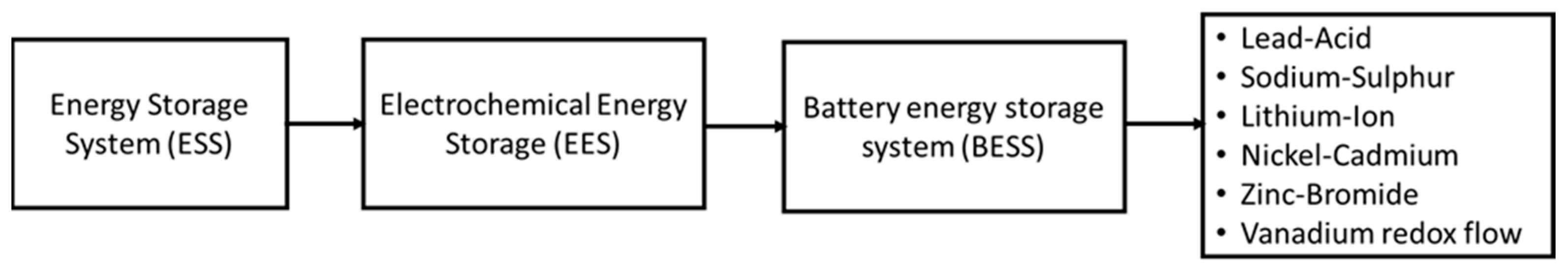
2. Battery Energy Storage Systems

The development of the RES has led to the disruption of conventional power grid operations due to the uncertainties and technical challenges faced by the intermittent nature of RES. This affects transmission grids and creates frequency variations, voltage violations, and network congestion [5]. To address these issues, the ESS, especially battery energy storage systems (BESSs), is a potential solution that can contribute to grid stability. The BESS offers many solutions, including suitable auxiliary services such as backup power supply, supporting peaking capacity, and facilitating energy shifting [6]. BESSs are also important for solving structural problems in the power grid and improving its stability [7,8,9,10]. In the transition to 100% renewable energy networks, a larger renewable energy capacity and ESSs are required to deal with the supply and demand mismatches caused by fluctuations and uncertainty in renewable resources [4].
Battery technologies, such as Lead–Acid, Sodium–Sulphur (NaS), Lithium-Ion (Li-ion), Nickel–Cadmium (NiCd), Zinc–Bromide (ZnBr), and Vanadium redox flow battery (VRFB) can be used as BESSs and integrated with RES to support different power systems. According to Kroposki et al. (2008) [11], batteries store electrical energy in the form of chemical energy during periods of high RES and, subsequently, release it during periods of low energy output to create a balance between supply and demand [12,13]. Furthermore, many batteries used with utility connections have bi-directional converters, which allow energy to be stored and taken from the batteries. The BESS can also provide an alternative solution to ensuring the sustainability of a fixed voltage and frequency operation through ancillary services while using renewable energy sources [14]. Some of the other benefits of BESS include stabilizing fluctuating energy sources and load changes, reliability, enabling load-sharing operations, reducing load spikes and electrical interference, and reducing the cost of ESS. Additionally, they can provide ride-through capability when there are dynamic variations in primary energy (such as those of sun, wind, and hydropower sources), provide energy management, ensure grid independence and stability, enhance efficiency, smooth the power output, and ensure the resiliency of microgrid operations while enabling the integration of renewable energy sources [11,12,15,16,17].
Other promising ES technologies have emerged over the years as potential solutions, which include compressed air energy storage (CAES), superconducting magnetic energy storage (SMES), electrochemical capacitor energy storage (ECES), and flywheel energy storage (FES) [3]. Figure 1 depicts the different classifications of ESS used in power systems and those that can be integrated with RES [13]. The schematic diagram showing the technological maturity of the ESS, particularly BESS technologies, is shown in Figure 2.
Referring to Figure 2, the level of maturity of different battery technologies has increased significantly. The Li-ion and redox flow batteries are at the optimum level compared to other battery technologies in terms of demonstration and deployment. However, these technologies’ usage for ES and commercial purposes is still very low due to their high capital requirement.

3. Battery Technologies

3.1. BESS Chemical Compositions

The chemical composition is the main component of the battery system and is often used to store electrical energy in the form of chemical energy. There is a wide range of existing batteries available for BESS, which includes Lead–Acid, Li-ion, NiCd, NaS, ZnBr, and VRFB. An extensive review of some of the most prominent research that has investigated the integration of BESS and RES with microgrid applications involving technologies such as Lead–Acid, Li-ion, NiCd, NaS, ZnBr, and VRFB for grid storage purposes is presented as follows.

3.1.1. Lead–Acid Batteries

Lead–Acid batteries are the most mature and commonly used rechargeable batteries, known for their performance, reliability, and low-cost battery technology [13,18]. The battery comprises a positive electrode made of lead dioxide (PbO2) and a negative electrode made of lead (Pb). These electrodes are inserted into a Sulphuric acid electrolyte where the charge and discharge reaction take place. The chemical composition of Lead–Acid is composed of the cathode and anode layer, which are represented by Equations (1) and (2).
At the cathode,
P b O 2 + S O 4 2 + 4 H + + 2 e     P b S O 4 + 2 H 2 O
At the anode,
P b + S O 4 2     P b S O 4 + 2 e
The following are some of the studies conducted to investigate the performance of Lead–Acid batteries.
Yang et al. (2023) [19] conducted a study on the optimal allocation method of the photovoltaic (PV) microgrid ES’s capacity based on empirical modal decomposition. The research problem of their study was that the PV system, which is one of the main components of distributed power generation systems, is connected to the grid through power electronics and does not have the frequency and voltage regulation characteristics usually found in synchronous generating units. Another issue found was that the allocation of ES in the microgrid systems is very low, which led to high battery usage in a year. The insufficient inertia of power electronics also affects the overall system performance in terms of grid security and stability. To solve this problem, an empirical modal decomposition (an optimal allocation method) was implemented to economically allocate a reasonable share of the Lead–Acid BESS’s power density and energy density in the microgrid system. This ensures that a PV system with high output impedance and inertia is produced at low operating costs to meet the safety and stability requirements of the grid. The empirical mode decomposition method is constructed alongside a PV and ES unit. The PV microgrid with hybrid ES was built in MATLAB/Simulink, operating under the off-grid mode. They found that the mean value of annual battery usage for the PV microgrid’s capacity was 53.74%, indicating that the proposed method is feasible when combined with an empirical modal decomposition algorithm. In Chen et al’s. (2023) [20] study, the optimal allocation methods based on an improved whale algorithm were implemented to enhance the configuration speed and pertinence of ES capacity monitoring nodes in distributed microgrids. The optimization approach improved the ES power of microgrids and reduced the difference adjustment coefficient.
In another study, Al Badwawi et al. (2018) [21] developed a supervisory control strategy for power management in an islanded AC microgrid using a frequency signaling-based fuzzy logic controller (FLC). The study also discusses the coordination and control of different units in a microgrid, including RES and BESS. Figure 3 shows the design of the proposed FLC. In this figure, the controller consists of two subsystems that vary the bus frequencies.
From Figure 3, the upper subsystem prevents the Lead–Acid battery from overcharging, while its charging power stays within its limits. The expression for the state of charge ( S O C u ) and charging power ( P c h a r g e ) for the upper subsystem are given as follows [22]:
S O C u = S O C m a x S O C S O C m a x S O C m i n
P c h a r g e = P c h a r g e   m a x P c h a r g e P c h a r g e   m a x
where
  • S O C is the state of charge.
  • S O C m a x is the maximum value of the state of charge.
  • P c h a r g e is the charging power.
  • P c h a r g e   m a x is the maximum charging power.
The expression for the state of charge ( S O C l ) and discharging power ( P d i s c h a r g e ) , for the lower subsystem is given as follows,
Δ S O C l = S O C S O C m i n S O C m i n + 10 % S O C m i n
Δ P d i s c h a r g e = P d i s c h a r g e   m a x P d i s c h a r g e P d i s c h a r g e   m a x
where
  • S O C m i n is the S O C minimum value.
  • S O C m i n + 10 % is the S O C minimum value plus 10%.
  • P d i s c h a r g e   is the discharging power.
  • P d i s c h a r g e   m a x is the maximum discharging power value.
The obtained results showed that by varying the bus frequencies, RESs were able to limit its power when required while the auxiliary unit reacted instantaneously to the supply power when the frequency was varied. In addition, they found that the proposed FLC was able to maintain the battery’s state of charge (SOC). The charging and discharging power of the battery’s limits were maintained despite the change in RES/load. The performance of the controller was better than the traditional droop control method. When comparing the FLC with the proportional controller used in the droop control method, the performance of the FLC was better at achieving the required objective. This is because the proportional controller was not able to maintain the FLC and ensure that the charging and discharging power limits were not exceeded.
Sharmila et al. (2021) [23] also performed a study that uses a Lead–Acid battery as an ESS and solar PV as the RES in a microgrid system. The study focuses on the implementation of a combined proportional–integral (PI) controller and hysteresis controller (CPIHC) method to efficiently manage dynamic power, regulate the DC link voltage, and control the battery’s SOC for a stand-alone DC microgrid system. The Lead–Acid battery voltage considered was a non-linear parameter and mainly depends on the temperature T of the electrolyte and the battery’s SOC, as given by Equation (7).
V m = V m o K [ 273 + T ] ( 1 S O C )
where
  • V m is the open circuit voltage in volts.
  • V m o is the open circuit voltage at full charge in volts.
  • K is the constant in volts/C.
  • T is the electrolyte temperature in C.
The approximated value of resistance, as seen from battery terminals, was assumed to be temperature independent and a function of SOC (defined as the ratio of the battery’s current capacity to the nominal capacity) of the battery, as given by Equation (8).
R s = R s r e f [ 1 + A ( 1 S O C ) ]
where
  • R s r e f is the value of R s for S O C = 1 (in ohms).
  • A is a constant.
  • The maximum SOC limit is 80% and the minimum SOC is 20%.
For Lead–Acid application with a BESS, a bidirectional converter and control algorithm were used to regulate the DC link voltage for varying solar irradiance. The DC link voltage increased when the user demand was less than the power generated from solar PV. Conversely, the DC link voltage decreased when the user demand was greater than the power generated from solar PV.
To improve the performance of the battery, the DC link voltage was maintained, which improved grid stability; Sharmila et al. (2021) [23] proposed a PI controller technique that controls the gating pulses of the battery, as shown in Figure 4. In Figure 4a, the controller makes a comparison between the Vdcref and Vdc and feeds it to the moving average filter. Thereafter, the battery reference current, Iref, is filtered through a ramp rate limiter that limits the charging and discharging levels. The Iref then corresponds with the actual current, I, value through a hysteresis controller to generate the switching pulses in the converter circuit, as shown in Figure 4b [23].
The simulation results from [23] show that the CPIHC is an efficient technique to manage the dynamic grid power response, improve stable operation, provide adequate regulation, and control the DC link voltage and battery’s SOC compared to the conventional combined PI and droop controllers (CPIDCs). In addition, the PI control technique was able to provide improved DC link voltage regulation and smooth power sharing. This study recommended that a supercapacitor be integrated to enhance the performance of the hybrid BESS.
Cecilia et al. (2020) [24] also investigated an optimal energy management system in a standalone microgrid with solar photovoltaic generation, short-term storage, and hydrogen production. This study provided insights into the use of Lead–Acid for dynamic power management, voltage regulation, and SOC control in microgrid systems. The proposed microgrid system consists of a Lead–Acid battery and is connected to the AC bus through a set of battery inverters per phase. The inverters are responsible for maintaining the voltage and frequency parameters of the microgrid. To determine the required control action for optimization, a model predictive control (MPC) scheme was used to predict the performance of RES and the load characteristics. A prediction horizon of 24 h, which amounts to a period of 72 h, was implemented using a sampling time of 10 min to obtain the value of factor N of 144. Furthermore, the controller required information about the battery power and SOC parameters. In the simulation, three profiles were used for the energy demand profile, the solar energy profile used in the MPC’s computations, and the solar energy profile used in the experimental data measured from a pyranometer. Figure 5 depicts the MPC scheme implemented by Cecilia et al. (2020) [24]. In this figure, the important parameters are the solar irradiance ( I c s ), the mean value of daily atmospheric turbidity ( T L ,   n 1 ), and load schedules, P c f l and P c i f l .
According to [24], the SOC of the Lead–Acid battery is given by Equation (9),
S O C = 1 C n 0 t f I b a t   d t  
where I b a t is the discharge current and C n is the nominal capacity.
The charged and discharged power of the battery depends on the difference between the PV panel’s power, P S O L   , and the power consumed by the system P c . The linear characterization of the SOC of the Lead–Acid battery from [24] is given by Equations (9) and (10):
d S O C d t = P c P S O L           1 C n V b a t ,   o c η i n v α c h   ( P S O L P c ) d S O C d t = P c > P S O L           1 C n V b a t ,   o c η i n v α c h   ( P S O L P c )
where
  • P c is the power consumed by the system.
  • P S O L is the power generated by the PV panels.
  • V b a t ,   o c is the battery open circuit voltage.
  • η i n v is the efficiency of the battery.
  • α c h is the battery charge efficiency.
The depth of discharge (DOD) is given as follows:
D O D = 100 S O C
The simulation results from [24] show that the incorporation of the MPC scheme stabilizes the battery SOC. Moreover, the energy demand is managed through changes in the schedule of deferrable loads, obtaining a reduction in the amount of energy cycled in the battery. The results also indicate that the use of MPC could reduce the storage needed, prolong the battery life, and reduce the investment and operating costs of the system.
In summary, several studies through optimization and performance enhancement have highlighted the importance of Lead–Acid batteries when used as an ESS in microgrid-connected systems. The control schemes that utilize controllers such as FLC, CPIDC, and MPC have been used to analyze Lead–Acid batteries in the SOC and DOD state. One common problem with Lead–Acid batteries is that they can sometimes experience a loss in capacity over time, known as sulfation, which can be mitigated through proper charging and maintenance practices. Studies recommend that more research (both simulation and experiment) should focus on the application of the MPC scheme to quantify energy and system costs with respect to the battery lifetime using several case studies. An accurate solar irradiance and battery subsystem models should be implemented to improve the controller performance. A more robust (stochastic variants) MPC should be investigated to improve the system performance.

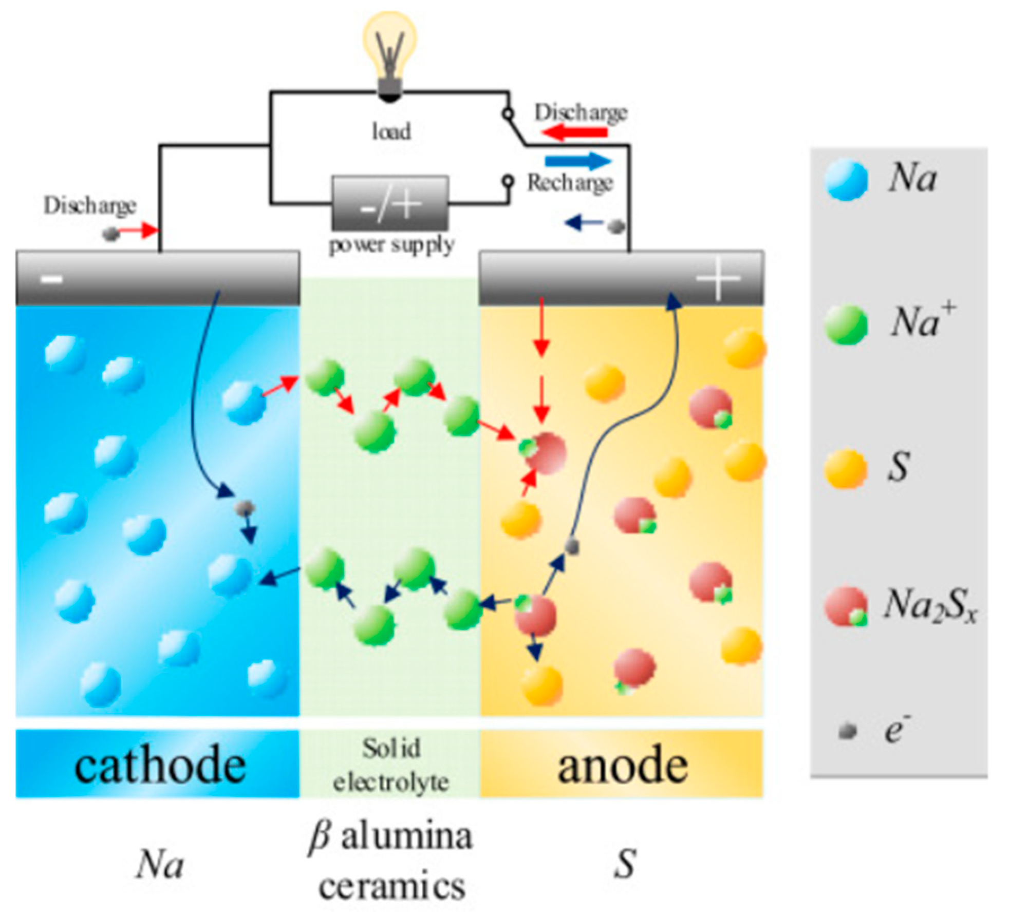
3.1.2. Sodium–Sulphur Batteries

Sodium–Sulphur (NaS) batteries are readily accessible and well-matched for grid applications. This battery technology is suitable for use in ES systems because of its high energy density [25]. This technology consists of Sodium as an anode and Sulphur as a cathode, while the electrolyte (separator) is made of Sodium Beta Alumina ceramics and has a low internal cell resistance. NaS batteries can also operate in liquid state form at temperatures ranging between 574 K and 624 K [26]. Figure 6 depicts the charging and discharging chemical reaction of a NaS battery. The typical working temperature of NaS batteries is between 300 °C and 350 °C to maintain the electrodes in a liquid state [27]. Some of the advantages of the NaS battery include its large capacity, low maintenance, high energy density, high efficiency, high lifetime cycles, pulse power capability, high durability, and high resistivity in case of self-discharging. The disadvantages are the high cost and temperature [28]. Furthermore, the self-discharge factor of NaS is very low, and the DOD can reach up to 100% with less degradation.
From Figure 6, the Sodium-ion (Na) cathode is combined with Sulphur within the electrolyte to form Sodium polysulfide (Na2Sx) in the discharging phase. However, the reverse is the case for the charging phase, as shown in Equation (12).
2 N a + x S D i s c h a r g i n g C h a r g i n g   N a 2 S x
where x value is within the range of 3 to 5.
Several studies have been conducted to investigate the performance of NaS batteries when integrated with a BESS. Among them is the study conducted by Saravanan et al. (2013) [30], where they use a scalable aqueous precipitation method to develop a Sodium-ion battery cathode material (Na3V2(PO4)3/C) with high-capacity retention, high energy density, high power density, ultra-long cycle life (30,000 cycles), and low cost in a large-scale ESS.
In another study, Iijima et al. (2010) [31] developed a system consisting of a 51 MW wind farm using 34 MW NaS batteries located at Futamata, Japan. A NaS battery system controller was placed between the common coupling point of the Tohoku Electric Power Company and the wind turbine in a feed-forward setting to improve the control response. Subsequently, the system performance test was performed from August 2008 to August 2009. The results showed that the NaS battery is suitable for constant output control to compensate for the fluctuation often experienced with the wind turbine.
Almarzooqi et al. (2023) [32] also evaluated the operation of a NaS battery system (BESS) integrated with a 13 MW capacity PV plant in Dubai. The goal of their study was to increase profit while using a linear optimization method to control the BESS with varying tariff plans and solar generation. The configuration of the proposed hybrid system is shown in Figure 7. In this system, the 7.2 MWH NaS BESS and PV subsystem are coupled separately to an inverter. A maximum power of 1.2 MW is then fed to the grid through a step-up transformer [32].
The SOC of NaS BESS is calculated as follows [32]:
S O C t = E t E m a x
where
  • E t represents the battery energy.
  • E m a x represents the maximum battery energy.
The simulation results from [32] show that the system profit increased by 0.27% for more than one week without grid penalties.
In summary, the use of the NaS battery system for ES presents interesting opportunities in power systems. The linear optimization control method and NaS battery system controller have been used in several studies to optimize NaS BESS coupled with PV, including the SOC level, charge, and discharge states. In addition, the battery system can be used for applications that require load leveling, RES power stabilization, and the minimization of voltage sag. The NaS battery contributes over 24% of the quantity of energy stored using BESS, which proves that it can be used for large-scale ES applications. A disadvantage to NaS battery systems in various applications is that it is very expensive because they must be operated at a high temperature of between 300 and 350 °C for Sodium and Sulphur to be converted into liquid. For future studies, it was suggested that the BESS sizing should be optimized using different electricity markets with the appropriate ancillary services, control strategy, and NaS thermal constraints.

3.1.3. Lithium-Ion Batteries

Lithium-Ion (Li-ion) batteries are commonly used in microgrid applications because of their high energy density, flexible design, and longer lifespan compared to other battery technologies. In the design of this battery, electrical energy is stored as chemical energy in two electrodes, a carbon material (anode or reductant) and a Lithium metal oxide (cathode or oxidant), separated by an electrolyte [33,34]. The electrolyte enables the movement of ions within the battery while forcing the electronic elements from the battery. One of the challenges faced in the design of Li-ion batteries for microgrid applications is the formation of a passivating surface layer on electrode/electrolyte surfaces, which increases the impedance of Li-ion transfer and lowers the cycle life of the battery [35]. Additionally, the formation of this passivation layer on the anode can irreversibly erase Li-ion from the cathode during the initial charge, which further reduces the reversible energy output of the battery. To address these challenges, an investigation needs to be carried out on how best electrode passivation layers can be controlled to improve the rate of Li-ion transfer across the electrode/electrolyte surface layer. This approach can further help in identifying electrolytes with larger windows to increase the density of stored energy [35]. The chemical composition of Lithium-Ion is composed of the cathode and anode layer, which are represented by Equations (14) and (15).
At the cathode,
L i M O 2     L i 1 x M O 2 + L i + + x e
At the anode,
C + x L i + + x e     L i x C
The overall reaction is as follows:
L i M O 2 + C L i x C + L i 1 x M O 2  
Several studies have been previously conducted with respect to the use of Li-ion batteries, including, among them, the work presented by study [36], where they used the Porous Electrode Theory (PET) method to predict and evaluate the effect of a dynamic positive electrode density in Li-ion battery cells. They evaluated the effect that manufacturing processes have on the performance of Li-ion batteries. They found that the cells with high positive electrode density produced a marginally higher discharge capacity when a low current was applied. The cells with a low positive electrode density produced a much better performance at high current rates.
In another study, Moncecchi et al. (2020) [37] focused on the development of a robust design to size a PV and BESS for electrification in a rural village in Tanzania. The design consists of two models of the Li-ion battery, namely, analytical, and electrical, which are then implemented in the robust design of an off-grid power system. For the empirical model described in [37], the SOC of the Li-ion battery is given as follows:
S O C   ( k ) = E B E S S ( k ) B E S S   s i z e × S O H   ( k 1 )
where S O H   ( k 1 ) is the assumed aging state of the BESS during time steps (k).
The state of health (SOH) is given as follows:
S O H   ( k ) = S O H   ( k 1 ) c y ( k ) × c f   ( k )  
c y   ( k ) = S O C   ( k ) S O C   ( k 1 ) 2
c f   ( k ) = 1 S O H m i n c y m a x  
where
  • c y represents equivalent cycle during the time step (k).
  • c f represents the capacity factor (capacity loss per cycle).
For the empirical model, a simplified series R-C circuit was proposed, as shown in Figure 8 [37].
The analytical and electrical models were designed using a MATLAB-based computational tool called POLItecnico di Milano—Network Robust desiGn (Poli.NRG). Their results showed that both BESS models had a significant effect on the battery SOC and SOH, the loss of load probability (LLP), and net present cost (NPC) estimations. In addition, a high-accuracy solution was obtained in the electrical model. However, degradation factors such as power fade and a higher simulation time made this method less reliable, unlike the analytical method, which is a more suitable model because degradation factors were considered. In general, these studies have highlighted that more attention should be given to uncertainties in equipment such as loads and generators when BESS is integrated into a DC off-grid power system.
Parthasarathy et al. (2023) [38] developed a peak power evolution and P-control model for active network management (ANM) using an equivalent circuit model (ECM) to manage the SOC and aging parameters for Li-ion batteries. The equivalent circuit was modeled in the second order with parameters such as the current rate and temperature levels. This study was conducted because Li-ion batteries age with use, and this causes the battery performance characteristics to degrade, which leads to a reduction in their charge and discharge capability. For these reasons, the BMS within the p-control model was implemented based on a second-order equivalent circuit of the Li-ion battery to produce accurate voltage, power, and energy characteristics. The goal was to ensure that the battery charging and discharging process fell within the peak active power performance threshold. The schematic diagram of the hybrid system is shown in Figure 9, while Figure 10 depicts the Li-ion battery PI controller for the charge and discharge phase.
In the modeling design, the Li-ion BESS is connected to the medium voltage (MV) bus system through a DC/AC converter interface and a voltage source controller (VSC). The system was verified using MATLAB Simulink Software. The simulation results from [38] showed that the magnitude of the defined BESS current, voltage, and power increases with respect to time. However, the BESS SOC decreases as the time increases up to 60 s, and then SOC gradually increases after 60 s. Furthermore, the BESS controller power decreases as time increases.
In summary, the use of the Li-ion battery system for ES in microgrid-connected systems has been discussed. The DC/DC and DC/AC converter and controllers, such as PI, current, charge, VSC, and discharge controllers, have been used in many studies to analyze the SOC and SOH of Li-ion batteries. For the estimation of SOC and SOH, it is necessary to include in the design of Li-ion BESS controllers’ adaptive secondary and tertiary controls in the aging parameter. This is necessary to avoid high-temperature problems such as overcharging and over-discharging, internal short circuit issues, and it also gives an early indication of when to replace depleted batteries [39]. In future studies, the Li-ion BESS can be modeled in steady-state and transient stability for multiple applications involving age and temperature parameters.

3.1.4. Nickel–Cadmium Batteries

Nickel–Cadmium (NiCd) batteries are cheap and robust technologies used in applications that require a long battery life or in extremely bad environmental conditions. The NiCd batteries consist of nickel oxide hydroxide (cathode) and metallic cadmium (anode), while the electrolyte is made of potassium hydroxide. The NiCd battery can perform extremely well at low temperatures between −20 °C and −40 °C. Moreover, comparing this battery with the Lead–Acid battery, this battery tolerates deep discharging and can store energy in the discharging state for a longer period compared to Lead–Acid batteries. NiCd batteries have an efficiency of approximately 70%. Figure 11 depicts the schematic diagram of NiCd electrolytic cells. In this figure, the cell consists of a positive (cathode: NiOOH) plate and a negative (anode: Cd) plate with a potassium hydroxide electrolyte separation layer between them. The maximum cell voltage of NiCd during the charge is 1.3 V, while the average voltage is 1.2 V. In terms of the discharge cycle, Ni(OH)2 is the active material of the positive cathode, while Cd (OH)2 is the active material of the negative anode. For the charge cycle, NiOOH is the active material of the positive cathode, while Cd is the active material of the negative anode, as shown in the following Equation [40].
The mathematical equation for the positive and negative electrodes of Ni-Cd electrolytic cells is given as follows [40].
At the cathode,
N i O O H + 2 H 2 O + 2 e   2 N i ( O H ) 2 + 2   O H
At the anode,
C d + 2   O H C d ( O H ) 2 + 2 e
The overall reaction is as follows:
N i O O H + C d + 2 H 2 O 2 N i ( O H ) 2 + C d ( O H ) 2
In study [41], they evaluated the performance of battery technologies such Lead–Acid, Li-ion, and NiCd when applied to microgrid systems. The aim was to compare the batteries’ SOC in terms of absorbing or delivering power during power fluctuations. The simulation was performed using the SCAMRE RT-LAB digital platform to study different battery case studies. The schematic diagram of the BESS structure is shown in Figure 12 [41].
The mathematical expression of the battery terminal voltage ( V b a t ) and SOC is given as follows:
V b a t = V o c + R b a t I b a t K Q b a t Q b a t + I b a t d t + A b a t ( B b a t I b a t d t )
S O C = 100 ( 1 + I b a t d t Q b a t )
where
  • V o c is the battery open circuit voltage.
  • R b a t represents the internal resistance of the battery.
  • I b a t is the battery charging current.
  • K represents the polarization voltage.
  • Q b a t is the battery capacity.
  • A b a t is the exponential voltage.
  • B b a t is exponential capacity.
The simulation results from [41] show that Li-ion batteries respond faster and produce a greater reduction in active power fluctuation for about 8 s compared to Lead–Acid (40 s) and NiCd batteries (38 s). Furthermore, the battery’s power absorbed or supplied is the same as the power from the main grid, which confirmed that BESSs compensated for the power losses or excess power in the microgrid. This also showed that BESS, with a fast response time, can provide peak load shaving, frequency regulation, voltage support, and grid stability.
In summary, the use of the NiCd batteries system for ES in microgrid systems has been discussed. The DC/DC and DC/AC converter and controllers such as battery-side and grid-side controllers have been implemented to analyze the terminal voltage and SOC of NiCd batteries. A disadvantage of NiCd batteries is that they are prone to self-discharge, which restricts their capacity for battery use. They are extremely toxic due to their composition [41]. For future studies, more comparisons should be conducted using experimental and real time simulations with respect to the development of BESS’s usage in power systems.

3.1.5. Zinc–Bromide Batteries

Zinc–Bromide (ZnBr) batteries are rechargeable and consist of zinc and bromine. They use an aqueous zinc nitrate bromine solution to produce electrical currents. Over the years, ESS technology has attracted attention as a potential ESS alternative to the Li-ion battery in stationary electrical applications, spanning from household to electricity. One of the important features of ZnBr batteries is that their electrodes are used during the chemical reaction. As a result, they have a high lifespan of operation, exceeding 2000 full-charge and discharge cycles compared to the conventional battery with 800 cycles [42]. There are two types of ZnBr batteries: (1) flow batteries and (2) ZnBr solid-state batteries. The flow battery uses zinc and bromide as active materials in the electrolyte, which is separated by a membrane. The zinc is plated during the charging cycle and then dissolves into the aqueous solution during the discharging cycle. During the charging and discharging cycle, zinc ions move from one side to the other side of the electrolyte tank, whereas the bromide remains in the solution. On the other hand, the solid-state ZnBr battery uses solid-state materials instead of liquid electrolytes to complete its chemical reactions. The chemical composition of ZnBr batteries in an electrolytic solution is given as follows:
At the cathode,
2 B r     B r 2 + 2 e
At the anode,
Z n 2 + 2 e     2 Z n
The following are some of the studies conducted to investigate the performance of ZnBr batteries.
Peng et al. (2015) [43] designed efficient fiber-shaped ZnBr batteries for flexible power sources. They focus on the development of a hybrid energy system combining ZnBr batteries and dye-sensitized solar cells. The identified problem is that flexible fiber batteries (FBs) remain a challenging process during production due to the problem experienced in obtaining properly active materials and resistant electrodes. Hence, they proposed a hybrid system consisting of two power fibers to achieve a high energy conversion efficiency and created a pathway for flexible, lightweight, and efficient power fibers. Their results showed that the system’s overall efficiency obtained was 3.4%, making it more suitable for large-scale production and can be used as an efficient power source.
In another study, ref. [44] performed the mathematical modeling of solar PV plants with a 50 kW ZnBr battery storage in a microgrid system. The aim was to model the ZnBr battery unit separately in terms of SOC, Rinternal, and open circuit voltage (OCV) calculations using the constant current charging and discharging technique in the MATLAB Simulink. The battery specifications include an energy density ranging from 85 to 90 Wh/kg, a power density from 300 to 600 W/kg, and a life cycle of 2000. The equivalent circuit diagram of the modeled ZnBr BESS is shown in Figure 13.
The mathematical expression of the SOC of the battery is given as follows:
S O C = 1 0 t i t d t  
where i t   is the discharge current.
The internal resistance of the battery depends on the SOC and the cell temperature, as given by the following:
R i n t e r n a l   ( S O C ) = 5.94 ( 0.13     S O C ) + 0.0254 ( 5.7 × 10 3     S O C )  
The OCV can be determined using the fourth-order polynomial function of SOC,
O C V   ( S O C ) = 1.8781 × 10 6 × S O C 4 + 5.2857 × 10 4 × S O C 3 0.0535 × S O C 2 + 2.3386 × S O C + 63.09636  
The terminal voltage for the equivalent circuit of ZnBr is given as
  V t   ( S O C ) = O C V   ( S O C )   R i n t e r n a l   ( S O C )     i t    
The resistance in parallel to the OCV (SOC) source in Figure 13 can be used to determine the self-discharging phase of the ZnBr battery.
  R s e l f   d i s c h a r g i n g   = O C V   ( S O C ) I   d i s c h a r g i n g   = O C V   ( S O C ) Δ q   l o s t   / Δ t
The simulation results show that the SOC of the ZnBr battery decreases at a constant discharging current from 80 A to 20 A, and the SOC linearly decreases at a constant discharging current from 100% to 25% and then linearly increases again after 4 min to 20 min, maintaining 100% percent SOC. The nominal capacity of the battery is 72 × 1.67 × 3600 = 102 Ah (432,000 A-s). Furthermore, after about 4 min of the constant rate discharging period, the OCV of the battery unit decreases from 105 V to 76 V, while the terminal voltage decreases from 108 V to 97 V. After 20 min, both OCV and the battery terminal voltage starts rising again to approximately 108 V and 107 V, respectively [44]. For self-discharging resistance, the average value was found to be 5.1 Ω using (32).
In summary, the SOC of a ZnBr battery for ES has been discussed. This study showed that the battery can be used to support the production of portable and efficient power sources. In addition, ZnBr battery ES models are suitable for renewable sources and electric power utilities that require industrial and commercial-sized devices. The drawback of this technology is that it has lower energy density, efficiency, and slower charging and discharging speeds compared to Li-ion batteries.

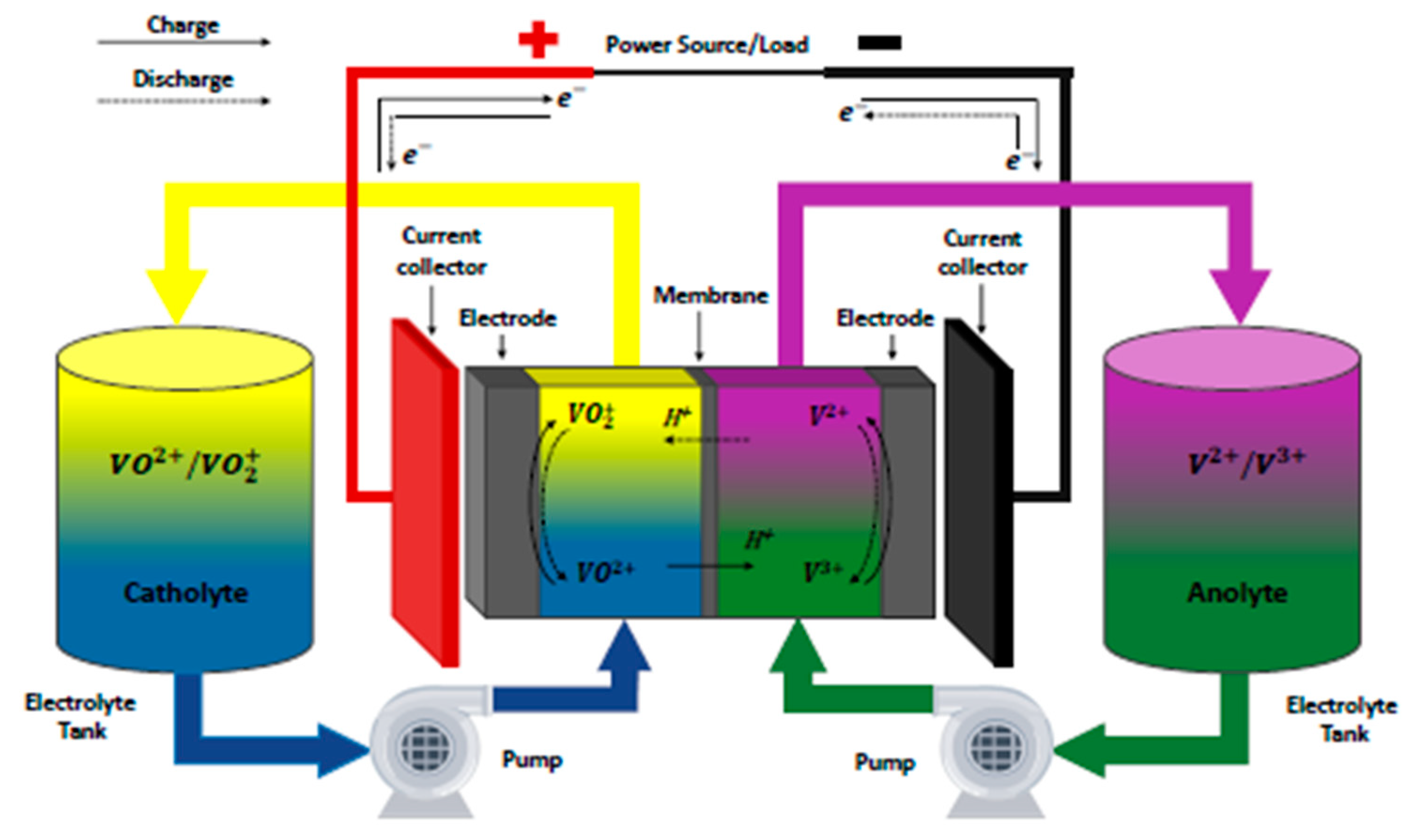
3.1.6. Redox Flow Batteries

Redox flow batteries, specifically VRFB, have been studied extensively for their integration with BESS in microgrid applications. These batteries’ composition consists of two liquid electrolytes, with one being negatively charged and the other positively charged. An ion-selective membrane is placed between the electrolytes to allow the independent flow of ions during the charging and discharging phase, as shown in Figure 14. In this figure, the energy stored after the chemical reaction corresponds to the electrolyte volume within the tanks. Moreover, the vanadium species concentration (V2+ and V5+) increases during the charging phase and decreases during the discharge phase, as shown in (33) and (34) [45].
The chemical composition of the VRFB is given as follows:
At the negative electrode,
V 2 + D i s c h a r g e C h a r g e   V 3 + + e
At the positive electrode,
V O 2 + + 2 H + + e D i s c h a r g e C h a r g e   V O 2 + + H 2 O
The mathematical expression of the SOC of the battery is given as follows:
S O C = E c u r r e n t E c a p a c i t y
The change in the SOC after each time step from the previous SOC is given as follows:
S O C   ( k + 1 ) = S O C   ( k ) + Δ S O C ( k )
The SOC of the VRFB is given as follows [46]:
S O C = S O C 0 + U s t a c k × I s t a c k P r a t i n g × T r a t i n g d t
Δ S O C = S O C 0 + U s t a c k × I s t a c k × t P r a t i n g × T r a t i n g
Δ S O C = V s t a c k × I s t a c k × C
where
  • U s t a c k represents the stack voltage.
  • I s t a c k represents the stack current.
  • P r a t i n g represents the battery power rating.
  • T r a t i n g represents the battery temperature rating.
  • C represents MATLAB constant block.
The stack voltage ( U s t a c k ) is given as follows:
U s t a c k = n   [ U 0 + R T F l n S O C 1 S O C ]
where
  • n represents the number of cells in series.
  • U 0 represents the internal cell voltage.
  • S O C represents a per-unit value of 0.5.
  • R represents the universal gas constant (8.314 J K 1 m o l 1 ).
  • T represents the temperature of the stack.
  • F represents Faraday’s constant (94,485.3399   m o l 1 ).
The following are some of the previous studies conducted to investigate the performance of redox flow batteries in power systems. Huang & Mu (2021) [46] performed a numerical study on a novel flow field design for VRFBs in microgrids to optimize the flow field structure, enhancing the overall efficiency of the batteries. In their study, various aspects, such as VRFB modeling, the optimization of the battery’s structural design, flow field and flow, stack design, thermal treatment, and temperature characteristic distribution, were reviewed and discussed. They found that the optimized VRFB, with a trapezoidal cross-section channel design, accelerated the electrolyte flow rate and improved the battery efficiency of the battery.
In another study, Babay et al. 2021 [47] developed a dynamic equivalent model of VFRB. The model consisted of subsystems such as solar PV, a maximum power point tracking (MPPT) controller, a DC–DC boost converter, and a VRFB storage system. The aim was to study the system flow rate and losses in power pumps. Figure 15 depicts the equivalent circuit of a practical VRFB model.
In Figure 15, the VRFB storage system was connected to a varying resistive load in the discharging phase and a solar PV in the charging phase. The VRFB model was developed using the MATLAB/Simulink environment platform to estimate the SOC of the battery. The simulation results showed that the VRFB’s SOC was maintained within the standard operating limit from 10% to 90%. This limit is important to prevent the high discharge that affects the battery’s lifetime. In addition, the VRFB delivers an active power of about 2.6 kW to 3.4 kW to the resistive loads with a maximum deviation of 0.063%. The VRFB’s SOC and battery voltage variation decreases over a period.
In Gong & Lei’s (2017) [49] study, a conventional model for the SOC estimation of the VRFB ES system was simplified to evaluate the feasibility and effectiveness of the battery. The simplified model comprised a bidirectional DC–DC converter in which the VRFB was charged and discharged under a constant current, and a PI controller was used to control the power flow between the VRFB storage system and the main utility grid. Figure 16 depicts the traditional VRFB equivalent circuit diagram, while Figure 17 shows the circuit diagram of a simplified VRFB.
For the modeling, the specification of the 5 kW VRFB ESS was entered into the MATLAB Simulink Software to evaluate and verify the proposed VRFB ESS and SOC estimation method based on the equivalent circuits in Figure 16 and Figure 17. The simulation results show that the estimated SOC values of the simplified VRFB model are very close to the conventional SOC value, as shown in Figure 18.
The results from Figure 18 show that the simplified model was very effective in showing the SOC of the battery when connected to the main AC grid. For future studies, it is recommended that the proper design of VRFB for ESS should be considered.
In another study, Ontiveros et al. (2017) [50] investigated the use of a VRFB coupled with a power conditioning system (PCS) to improve the frequency stability of a microgrid in a wind turbine system. The microgrid system consists of a constant load, steam turbine (10 MVA), eight double-fed induction generator (DFIG) wind turbines (12 MW), and a 1.5 MW VRFB unit, with a thyristor converter, commutated capacitors (TCCC) and infinite grid voltage of 132 kV. The control system is composed of low-level, mid-level, and high-level controllers, as shown in Figure 19.
The entire system is modeled using the SimPowerSystems unit within the MATLAB/Simulink software. The simulation results revealed that the TCCC/VRFB unit, alongside the load-leveling controller, was effectively able to compensate for the active power fluctuations generated by the wind turbine. This system generates a better and smoother power response compared to systems without the TCCC/VRFB unit. In addition, the TCCC/VRFB unit, alongside the primary frequency control (PFC) and secondary frequency control (SFC) controllers, effectively contributed to frequency recovery during extreme disturbances occurring in the microgrid.
In summary, the SOC of a VRFB battery for ES has been discussed. The studies show that the VRFB SOC operating limit was maintained. Moreover, since the VRFB SOC and battery voltage transition decreased over a long period of time, the battery lifetime was prolonged in the process. Furthermore, the incorporation of the VRFB with thyristor converters and controllers (PFCs and SFCs) was shown to improve the system’s performance when integrating renewable energy sources such as wind turbines and PV with the AC microgrid. These studies show that when the VRFB is used as ES, it can effectively support the main utility grid by providing an appropriate VRFB SOC status. Other advantages of VRFB include the fact that it offers flexible design, high safety, and long service life. These advantages were emphasized in the study conducted by [34], where lower costs and improved VRFBs were used for grid-scale ES systems. The main drawback of the VRFB system is that it does not take into consideration the effect of the system’s dynamic flow rate when implementing estimation strategies. Another demerit of this technology is that each VRFB cell that matches the stack does not behave the same way. A possible solution is to develop new estimation models that include shunt current and temperature gradients within the stack [45]. Another drawback of the VRFB system is the self-discharge problem caused by the low ion selectivity of membranes. This has led to the low efficiency and fast decay of the battery mainly caused by the migration of VRFB ions through ion-exchange membranes [52]. A possible solution is to improve the development of the VRFB’s components. Future recommended studies relating to VRFB energy storage are as follows:
  • A new RFB storage system with novel electrolyte chemical compositions should be modeled and compared to VRFB.
  • The impact of the temperature and aging status using varying VRFB parameters should be investigated.
  • The development of new models for different VRFB cell integration with parameters such as stack shunt currents and temperature gradients.
  • The development of strategies to optimize the VRFB particle flow rate and minimize power consumption.
  • The development of an improved SOC estimation for imbalanced VFRB electrolytes.

3.2. Technical Analysis of BESS Technologies

The performance characteristics of the five BESS technologies for Lead–Acid batteries, Li-ion batteries, NaS batteries, ZnBr batteries, and the VRFB are presented in this section. To select the appropriate technology for different applications, the criteria are often used depending on the battery recharging ability, safety, space and weight characteristics, and round-trip efficiency during the charging–discharging process. The performance comparison of several battery technologies is shown in Table 1. In this table, Li-ion batteries have high energy density (≈180 Wh/kg), power density (≈315 W/kg), and high efficiency (≈98%) when compared to other battery technologies. Vanadium redox flow batteries, on the other hand, have a long life (≥12,000 cycles). They are flexible and can be used for storing medium and large amounts of energy. Vanadium redox flow battery technologies have a low energy density (≈150 Wh/kg) characteristic that limits its capacity to be used for large-scale ESS applications such as peak shaving and the energy time shift. Lead–Acid batteries, because of their low energy density (≈300 Wh/kg), low life (≈3000 cycles), and long charging times, can only be used in combination with small PV systems, but not with larger-scale renewable ES systems. NaS batteries, on the other hand, have excellent charge and discharge efficiency, a long lifetime (≈5000 cycles), and a high energy density (≈120 Wh/kg), which is five times higher than that of Lead–Acid batteries (≈35 Wh/kg). The performance characteristics of NaS show that they can be used as a stand-alone renewable energy source or as arbitrage power to complement energy systems. Comparing the cell voltage for the different battery technologies considered, Li-ion batteries produce the highest cell voltage (2.5 to 5 V), followed by NaS and Lead–Acid batteries, which also have a high cell voltage level. The VRFB produces the lowest cell voltage.
From a technical standpoint, the data presented in Table 1, the most suitable technologies for the frequency of regulation application are Li-ion batteries due to their high power (150 to 315 W/kg) and energy density (120 to 180 Wh/kg) characteristics. In addition, considering an economic point of view, the BESS offers services that are cheaper compared to the conventional power system. Among the battery technologies used in certain electrical applications, Li-ion-based batteries are the most applicable due to their good performance characteristics. Furthermore, technologies such as Li-ion, Lead–Acid, and NaS are more suitable for frequency regulation applications due to their fast response in supplying and absorbing energy. Common relationships observed among some of the battery characteristics for large-scale ESs are reduced costs and improved scalability, especially Li-ion, NaS, and redox flow. The choice of these batteries depends mostly on their specific applications, energy capacity, budgetary requirements, geographical location, and technology maturity. Furthermore, to leverage the characteristics of each battery, the optimization of these batteries in terms of charging and discharging behaviors and a smart control management system must be considered to maximize efficiency.
The environmental factors that should be considered before implementing BESS are resource extraction, energy intensity, end-of-life management, land use, life cycle, and grid integration. For instance, battery technologies like lithium and nickel pose potential risks of habitat destruction, water pollution, soil erosion, and the destruction of ecosystems. To mitigate these risks, efforts must be made in terms of policies to provide a proper geographical location for the installation of BESS. The high energy intensity of BESS could potentially lead to greenhouse gas emissions. In addition, the improper disposal of BESS could lead to soil and water contamination. To combat this problem, an effective recycling process must be developed. Considerations such as the overloading of the grid could result in the over-reliance of the BESS resource technology. A solution to this is to balance the environmental benefits and drawbacks by implementing the effective management of BESS.

3.3. Current and Future Battery Technologies for Energy Storage in Utilities

This section discusses the latest and future battery technologies that can be used with the BESS to achieve the following application objectives such as power smoothing, frequency regulation, voltage control, load leveling, and hybrid energy storage system (HESS) integration. Some of the challenges encountered with BESSs are self-discharge and material degradation, which limits its potential for storage capabilities. In the future, a long-term hydrogen ES would serve as a promising solution because of its high energy density and stability compared to the BESS. Hydrogen ES also offers solutions for long-term charging and discharging since it is based on an electrolysis and fuel cell combustion system. This would also serve as a potential solution in the reduction in capital costs compared to the BESS. Even though BESSs offer a very high round-trip efficiency, the hydrogen ES offers long-period solutions for RES plant shutdown. Moreover, hydrogen geological storage systems could be investigated to study the effects of geological locations on hydrogen losses and performances. From an industrial perspective, several chemical hydrogen ES, especially ammonia and methanol, could outperform hydrogen liquefaction for ES applications. Lastly, major technical challenges such as hydrogen carrier combustion and external fuel could be solved by hydrogen ES in the future. Some of the future BESSs and other technologies that have been identified in the literature, together with their objectives and outcomes, are summarized in Table 2.
Table 3 summarizes the use of BESSs based on industry perspectives and applications to understand the past and recent development trends.
In summary, the charge, discharge, SOC, and SOH of battery technologies such as Lead–Acid, NaS, Li-ion, NiCd, ZnBr, and VRFB in microgrid-connected systems are discussed in this section. The analysis of each battery system was performed using their respective DC/DC converter, DC/AC converter, and PI and VSI controllers. Furthermore, Li-ion, Sodium-based, and flow redox batteries have seen increased breakthroughs in the ES market. Moreover, Lead–Acid, Li-ion, NaS, and redox flow batteries lead the way in terms of power systems usage. Li-ion batteries represent about 18% of the quantity of energy stored using BESS compared to Lead–Acid (18%), NaS (24%), and VRFB (25%). Hence, they are commonly used due to their good overall characteristics, such as lifetime cycles, efficiency, energy density, and power density, which have grown significantly in the current energy storage market. After the Li-ion battery, it is followed by the NaS, VRFB, and Lead–Acid battery. For the DSEM, techniques such as the Newton-Weighted Sum Frisch method (NWSFA), novel equalization management system (EMQS), Calliope Mixed-Integer Linear Programming (MILP) algorithm, LEAP-NEMO interface model and FLC and DC–DC control strategies have been identified and implemented to tackle RES fluctuation issues. From an industrial perspective, the BESS has been used for peak load shaving, the smoothing of PV ramp rates, and voltage fluctuation reduction, RES, large grid, power supply backup, microgrids, RES time shift, the spinning reserve for industrial consumers, and frequency regulation. The above characteristics are the merits of different battery technologies.
Some of the factors that can affect BMS failures are design and quality, environmental considerations, the overcharging and discharging of the batteries, production faults, software glitches, component degradation, physical damage to equipment, and lack of maintenance. To mitigate against possible BMS failures, manufacturers and operators should implement the following solutions:
  • The use of robust and high-quality components.
  • Adhering strictly to installation guidelines.
  • Thorough quality assurance checks should be conducted.
  • The proper scheduling and regular maintenance of equipment.
  • The regular training of personnel handling the operation and maintenance of the BMS.
  • Adhering to policies and environmental regulations.

4. BESS Ancillary Services

The BESS is significant in providing ancillary services to the grid. The BESS plays a crucial role in facilitating the integration of RES into the grid by compensating for the fluctuations produced by RESs as intermittent resources [66]. Ancillary services encompass all the services necessary for the grid operator (transmission and distribution operator) to maintain the system’s integrity, stability, and power quality [67]. Grid operators ensure a reliable power supply, frequency, voltage, and power load within certain limits. The schematic diagram of different ancillary services in BESSs is shown in Figure 20 [68].

4.1. Evolution and Development of Bess Ancillary Services

Over recent years, research and development have demonstrated the significant evolution of grid ancillary services. These research studies have focused on various crucial services required by the grid, including the integration of RES and BESS, the impact of high-voltage and direct-current (HVDC) grids on ancillary services, the utilization of electric vehicle grid integration systems (EVGI) and the evaluation of grid performance [6,7,69,70,71]. The exploration of distributed energy resource (DES) interconnection codes with PV inverters has also been assessed [72]. Ancillary services work on peak load shifting, frequency regulation, voltage support, smoothing variable generation from renewables, and the optimization of power system operations [73]. Furthermore, potential control strategies have been explored for electric vehicles (EVs) to participate in ancillary services [74]. Multiperiod optimum power flow solutions for active distribution networks have been investigated by [72,75,76]. The feasibility of using a BESS for ancillary services depends on battery investment costs, self-consumption advantages, grid optimization, and applications, as shown in Figure 21 [66,77].
The potential challenges that can be addressed by BESS ancillary services are shown in Figure 22. These challenges involve battery degradation, economic concerns, environmental threats, regulatory barriers, the charging and discharging of BESS, and dynamic impacts [6].
The following BESS ancillary services have been identified as a potential solution to provide support and overcome some of the above challenges:
  • Frequency regulation.
  • Congestion relief.
  • Voltage support.
  • Power smoothing (flow control between RES and the grid).
  • Peak shaving (demand-side energy management).

4.1.1. BESSs for Frequency Regulation

The BESS has shown remarkable effectiveness in offering diverse ancillary services to the grid and microgrid. Among these services, it provides frequency regulation in response to changes in grid frequency, quickly adjusting by either injecting or absorbing power. This dynamic response helps maintain a stable frequency within the desired range, preserving grid stability and a reliable power supply [78].
One crucial feature of BESSs for frequency regulation is their optimal placement and storage system sizing. It was observed that the optimal size of BESSs could result in a high-frequency control performance when utilizing the Particle Swarm Optimization (PSO) algorithm compared to other sizing algorithms [79]. The selection of the optimal sizing of BESS depends on parameters such as load-shedding schemes and contingencies [79]. To avoid unnecessary power consumption by BESSs and the smoothing of power grid frequency, diverse control strategies have been developed to enhance frequency regulation. These strategies aim to mitigate the fluctuations in renewable energy generation and monitor the battery state of charge (SOC) [79]. This system’s capacity limit is controlled by a strategy that allows the BESS to switch between frequency regulation and the recharge control strategy [80]. Another approach to the control strategy regulates the frequency between BESS and traditional generators by considering factors such as battery state of charge, the frequency modulation effect, and system economy for optimum results. The BESS centralized control strategy is commonly utilized for frequency regulation [81]. However, a distributed local control-based BESS has high output performances and effectiveness with a faster response between the BESS and other power generation sources.
Frequency control in a microgrid is divided into three levels, namely, primary control, secondary control, and tertiary control. The primary control employs the use of droop control without any communication network [82,83]. This method uses fast stabilizing control actions and can be implemented by voltage and current loops [84]. The secondary control employs microgrid central controllers such as slow control loops and low bandwidth communication systems. These systems are used to measure parameters at certain points of the microgrid and to send back the control output information to each microgrid unit [84]. The tertiary control employs the economic dispatch of DES, which is related to economic optimization [82]. This type of control exchanges relevant information with the Distribution System Operator (DSO) and the optimization of microgrid operation within the utility grid [80].
Ref. [67] is study that covered the voltage and frequency regulation for both distribution and transmission grids. This study addresses load-shedding challenges in South African power networks and offers a list of references related to voltage control techniques. In addition, more studies have efficiently underlined BESS’s frequency regulation. It has been shown in the all-island Irish transmission system that implementing the appropriate BESS capacity could successfully decrease grid frequency fluctuations [85]. Furthermore, economic models and the fuzzy logic theory have also been conducted to optimize the frequency regulation strategy of BESSs. The BESS is vital for maintaining stable power grid frequencies, particularly when RESs are involved. Strategic positioning, sizing, and control methods are used to optimize the BESS’s effectiveness.

4.1.2. BESSs for Congestion Relief

The BESS presents an efficient alternative solution for congestion relief in power grids [6]. It overcomes the limits of traditional methods, such as network configuration and load rescheduling [6]. Moreover, the BESS is utilized as a black start for congestion relief in distribution grids [6]. The following are some of the control strategies and optimization techniques used in BESSs for congestion relief.
Adaptive control algorithms have been developed to control the action of the BESS for voltage regulation and congestion status in distribution grids. Likewise, coordinated control strategies integrating BESSs with other devices, such as on-load tap changers, have been used for voltage regulation and congestion relief [6].
Real-time control frameworks and dispatch algorithms have been proposed to optimize the revenue of BESSs in delivering grid services, including congestion relief [86]. These frameworks underline the potential gains of using the BESS for congestion management in power systems. Disruption can be alleviated by strategically deploying BESSs in the transmission network, which can avoid the need for costly infrastructure upgrades [87].

4.1.3. BESSs for Voltage Support

The BESS has gained recognition for being a solution that contributes to voltage support in power systems, especially when integrating a substantial amount of PV generation into the system [88]. The unstable nature of PV generation often induces voltage fluctuations. Therefore, the BESS can be used to regulate and stabilize the voltage levels of the system [88]. An obstacle when employing the BESS for voltage support is the constant charging/discharging cycles, which directly affect the system’s cost and longevity [6]. The following methods can be used to respond quickly to the fluctuations in PV power and maintain voltage stability. For example, the real-time coordination control strategy has been developed to improve the performance of PV inverters and BESSs for voltage regulation [88]. The moving average algorithm has been commonly used to improve voltage support by smoothing the PV power output. However, the constant charging/discharging implemented by this algorithm can degrade the BESS’s lifespan and create economic drawbacks [6]. Another efficient control strategy has been developed to dynamically adjust the charging and discharging power of the BESS accordingly to prevent premature energy depletion and optimize its overall lifespan [6]. Moreover, the interaction between step voltage regulators (SVRs), PV inverters, and BESSs has been studied for voltage regulation without relying on electronic communication [88]. This interaction is established via a voltage margin control strategy, which guarantees adequate voltage support within the system [88].

4.1.4. BESSs for Power Smoothing

The BESS offers fast response times, modularity, and scalability, making it suitable for applications in power systems [16]. Through fast discharging or charging, the fast-response time deals with the fluctuation in supply or demand. Optimization control and management are essential for addressing RES integration challenges [89]. The integration effect of large-scale BESSs to tackle the problem of the fluctuation and intermittency of renewable power to the grid has been previously investigated. The investigation findings showed that the BESS improved the grid stability and transmission network’s operation [89].
The interaction of the BESS with PV systems performance has also been previously studied. In [90], their study mitigated voltage unbalance and network losses by applying a battery-powered flow control algorithm and injecting real and reactive power into the grid. Furthermore, BESS’s optimal planning and sizing for frequency control in power grids have been widely considered when penetrating renewable RESs and the grid [6]. Integrating the BESS into the microgrid can deliver main and auxiliary services for reliable and efficient power flow control [91]. In another study, ref. [13] investigated various types of BESS and RES usage in power systems. The objective was to generate renewable energy using different scheduling periods. Their results showed that BESS can assist power distribution suppliers by mitigating and smoothing the overall power fluctuations caused by RES intermittent issues.

4.1.5. BESS for Demand-Side Energy Management

The implementation of demand-side energy management (DSEM) programs through customer participation is an important factor that is required to achieve total load optimization as well as a reduction in the microgrid investment cost [92]. The aim of DSEM programs is to change the energy consumption behavior of customers by consuming less power during peak hours and more power in the off-peak hours [93]. The DSEM can be divided into the following two categories: the load demand response (LDR) and energy efficiency (EE). The goal is to reduce customers’ peak energy demand, minimize energy consumption costs, reduce the peak-to-average ratio (PAR), minimize user discomfort by changing the operating behavior of devices, and increase the use of energy generated from local sources. Figure 23 depicts the classification of DSEM [93].

Load Demand Response

The LDR program provides an avenue to control the load behavior on the network instead of the supplied power. This is conducted through demand shifts and curtailment during the peak periods to reduce cost and maintain a balance between the electric power and the load. The demand response (DR) is grouped into two categories as follows: incentive-oriented or price-oriented programs.
The incentive-oriented program consists of direct load control (DLC), curtailable load (CL), and demand-side bidding (DSB). In the DLC method, the main utilities regulate heavy customers’ loads and appliances during peak demands by turning them off. Some of these heavy loads include air conditioners, microwaves, ovens, refrigerators, and cooling devices. In the CL method, the main utility proposes demand adjustment schedules, while the user controls the usage of appliances. Moreover, rewards are given to users who comply with these schedules while penalty fees are levied on those who disobey them. In the DSB (load shifting) method, users can adjust their loads to improve peak load shaving based on a bidding request in an electricity market [94]. The loads are shifted and distributed evenly without affecting the total consumed energy. Moreover, this program ensures that demand and supply are maintained at the required level while increasing the system’s efficiency.
The price-oriented program consists of the time of use (TOU), critical peak pricing (CPP), real-time pricing (RTP), and inclined block rate (IBR), as shown in Figure 24 [95].
The TOU program enables the main utility to remotely regulate customers’ appliances by setting different prices for usage times. In this program, the cost of electricity is determined by how much electricity is consumed by the users [94,96]. In the CPP program, a flat pricing strategy or TOU tariff is used annually as an alternative option for small-size peak load usage periods. According to Bakare et al. 2023 [95], energy users who participate in DR programs through the CPP method experience a significant reduction in the cost of energy usage, especially in countries such as North America and Sweden. In the RTP program, spot pricing is implemented on an hourly basis. Hence, energy users are notified hours or days ahead, depending on their electricity market schedules. One limitation of this method is that it is extremely difficult for energy users to actively enroll due to the vigorous back-and-forth communication required by both the utilities (energy providers) and the consumers. According to Bakare et al. 2023, RTP is recommended as a method that can be used to improve system stability at a low cost with good environmental impacts, especially in the USA. The IBR program is used alongside the RTP or TOU price signals. This method, when coupled with TOU, can boost the scheme’s efficacy and the pricing scheme in terms of energy cost and system stability.
The control strategies often used in DR programs include peak load shaving, valley filling, load leveling, load shifting, and energy arbitrage.
  • Peak load shaving
Peak load shaving or clipping is a traditional DR technique that cuts some portion of users’ loads during peak hours and when consumer demands are very high. BESS is commonly used in peak load shaving to effectively reduce the power grid’s peak demand. Furthermore, during periods of high demand, the BESS can discharge stored energy to meet the increased load, reducing the stress/tension on the grid and possibly avoiding the need for high-cost infrastructure upgrades. The impacts of the peak load shaving and BESS strategies when used with RES in the energy markets have been addressed in the literature. Ref. [97] investigated a residential microgrid, consisting of 144 households, PV, a wind turbine, and BESS. They used a Lead–Acid BESS to overcome the fluctuations caused by the intermittent nature of RES, while the DSM scheme was implemented to shift the peak loads by an hour when the user demand was very low. The results obtained showed that the optimized renewables mix was able to reduce demand fluctuations and improve energy balance. The peak load demand fluctuation per hour in the microgrid was reduced by 19% (12% with renewables mix, 4.6% with a BESS, and 3.5% with DSEM), with one renewable unit and four batteries per household, 83% PV panels and 17% wind turbines. In another study, Hosseini et al. (2019) [98] presented a DSEM method based on robust model predictive control (RMPC) for residential smart grids, which consist of multiple interconnected homes, Lead–Acid and Li-ion BESSs. The aim was to reduce users’ energy bills and PAR. The effectiveness of the proposed method was validated via a case study. The simulation results showed that the RMPC method provides a higher PAR value in terms of the budget of uncertainty. The suggested future work is to combine this model with other subsystems such as distributed generators, non-interruptible loads, RES, and multi-agent large-scale residential smart grids.
In another study, Li et al. (2019) [99] concentrated on synchronizing energy-intensive loads (EILs) with a BESS to reduce peak shaving using an optimization framework. This framework includes the neural network algorithm that balances the system operation expenses and wind energy curtailment costs. Papadopoulos et al. (2020) [100] investigated the economic viability of peak shaving with the BESS on real power, charging, and discharging rates. The aim was to analyze the economics of grid-level energy storage for load-shaving applications and the potential of peak shaving through BESSs for low-voltage enterprises with peak demand pricing. The results indicate the economic benefits for certain end-users [100]. Yao et al. (2015) [101] proposed an independent energy scheduling strategy to deal with the challenge of voltage deviation in home energy management systems (HEMSs). Moreover, the DSEM was employed using optimal charging methods to bring down the high peak load demand in plug-in electric vehicles (PHEVs). This approach led to increased power network reliability, reduced cost of system operations, and BESS’s efficiency increased [102,103]. The benefits of peak shaving have also been identified by Molderink et al. (2010a, b) [104] as a potential solution to varying productions and demands of electricity and additional unpredictable loads, especially EVs.
  • Valley filling
Valley fillings are periods when low demand is experienced with respect to base loads. In this technique, the use of the BESS and transferable loads can be used to curtail excess energy generation. The impacts of the valley filling and BESS strategies in the energy markets have been addressed in the literature. Augusto et al. (2017a) [105] investigated a valley-filling strategy to restrict transferable loads to off-peak demand scenarios. Their results highlighted the importance of DSEM measures with the reduced levelized cost of electricity to around 18%. Valley fillings have also been investigated by [106], where EVs from a PV/grid system were charged using a rule-based EM system (REMIS).
  • Load leveling
Load leveling is the strategy required for large load fluctuations. In this method, the differences between the peak and low demand profiles are significantly reduced. The impacts of the load leveling, and BESS strategies have been addressed in the literature. Agamah and Ekonomou (2017a) [107] investigated the combination of Lithium-Ion BESSs and the peak demand schedule to improve load leveling and achieve peak demand reduction using genetic algorithm combinatorial optimization (GACO) genetic algorithms. The result obtained showed that the peak load demand was reduced to about 7.69% without combinatorial optimization (GA). When the GA and BESS parameters were introduced, the peak load demand was reduced by 8%. In another study, Papic et al. (2006) [108] developed a simulation model for the load leveling of a Lead–Acid BESS for several hours. The discharge model was based on the power (Ah) of the BESS and load measurements at constant discharging currents. The simulation results showed that the successful shaving of peak loads was achieved with the appropriate active power reference setting. A future research direction is to focus on the impact of the population and battery size. The BESS’s development and practical installations with different approaches should be investigated.
  • Load shifting
Load shifting is a strategy that involves transferring load demands among different users based on the transferability of such loads and supply availability. The impacts of the load shifting, and BESS strategies have been addressed in the literature. Sepulveda et al. 2018 [109] presented a study that focused on the optimal determination of the best site and size for BESSs in a PV/wind turbine distribution system. The proposed model implemented a genetic algorithm and was tested using the IEEE 123 nodes system (OPENDSS) in MATLAB. The results showed that the grid’s power reverse flow was mitigated, and the cost of energy was reduced, specifically with the BESS. A future research direction is to focus on the implementation of OPENDSS algorithms to study the effect of devices such as voltage regulators and capacitors on this network.
  • Energy arbitrage
Energy arbitrage is a strategy that can be used to store energy at the time of excess production for use at a time when the power supplies are very low. This strategy is mostly suitable for RES-based systems and can be achieved with a BESS, supercapacitor, air, water, hydrogen, and EV storage [110]. The impacts of energy arbitrage and BESS strategies have been addressed in the literature. Salles et al. (2016) [111] presented a study that used energy arbitrage techniques to improve revenue based on the price volatility in 7395 different electricity markets. In another study, [112] investigated an extended-term BESS arbitrage problem using a bi-level BESS arbitrage solution with high wind power penetration. The bi-level ES arbitrage model consists of an upper level where the ES arbitrage revenue is maximized, with a lower level where the market clearing process is conducted. The simulation result showed that the BESS power and energy ratings should be significantly reduced to achieve a medium-to-high percentage of the optimum revenue. Other DSEM effects on the RES and BESS are presented in Table 4. A future research direction is to investigate different strategies that can be used to improve the arbitrage revenue price using several BESS systems [113].

Energy Efficiency

Energy efficiency is a system of DR that provides energy customers with a favorable service that can require less energy consumption and is economically profitable. Moreover, this method often reduces huge power losses [120]. The characteristics of energy efficiency techniques are presented as follows [121]:
  • Efficient energy devices in households with constant awareness programs towards the better use of energy. An example is using energy-saving bulbs, such as incandescent bulbs and energy-saving air conditioners.
  • Performance check routine with optimal maintenance techniques on electric power equipment should be promoted. An example is recovering heat from waste products.
  • The utilization of distributed generation, optimized control systems for voltage regulation, load flow power factor correction on networks, and data acquisition systems using fiber optics, smart meters, and advanced transformers should be promoted.
In summary, BESS ancillary services (frequency regulation, grid congestion relief, voltage support, power smoothing, and DSEM) for different applications are discussed in this section. On the consumer side, the important criteria to consider when implementing DSEM with a BESS are RES integration, behind-the-meter energy consumption, the load profile of appliances, load categorization, constraints, dynamic pricing, and consumer behaviors. The potential solutions that have been identified to tackle these criteria are peak load shaving, valley filling, load leveling, load shifting, and energy arbitrage. Many control strategies or programs used in the DSEM assist in reducing the wastage of energy, curbing energy consumption when power supplies are very low, and minimizing energy and system costs.

5. Economic Analysis of BESS Technologies

In this section, the cost of five BESS technologies, such as Lead–Acid, Li-ion, NaS, ZnBr, and VRFB, are evaluated and compared for the years between 2018 and 2025. As shown in Table 5, the total cost of the project for redox flow batteries was USD 858/kWh in 2018 and is projected to be about USD 650/kWh in 2025. This high cost shows that VRFB technologies are very expensive compared to other batteries such as Lead–Acid (USD 549/kWh in 2018 and USD 464/kWh in 2025), Li-ion (USD 469/kWh in 2018 and USD 362/kWh in 2025), NaS (USD 907/kWh in 2018 and USD 669/kWh in 2025), and ZnBr (USD 551/kWh in 2018 and USD 433/kWh in 2025). In terms of lifespan, the cost of ES technologies (such as Lead–Acid, NaS, Li-ion, NiCd, ZnBr, and VRFB) for commercial usage consists of operating and capital costs. Most of the time, the operating costs cover the running cost, maintenance, recycling, and replacement, while the capital cost includes the ancillary services components. These costs are vital for the economic feasibility of ES technologies. For capital cost per kWh, Lead–Acid ES has about USD 1000–2000/kW for a lifetime exceeding 20 years. Furthermore, NaS has about USD 1000–30,000/kW for a lifetime between 10 and 15 years and a 2500 cycle life. Other batteries like ZnBr have about USD 700–2500/kW for a lifetime between 5 and 10 years and a lifetime exceeding 2000 cycles. VRFB has about USD 600–1500/kW for a lifetime between 5 and 10 years and a lifetime exceeding 12,000-cycles. For Li-on, it has about USD 1200–4000/kW for a life cycle of 5 years. Lastly, NiCd batteries are characterized by their long life of 3000 cycles. However, the energy cost, which is ten times more than Lead–Acid (USD 10,000/kW), often determines its application usage for ES. There are also some concerns regarding the toxicity of the battery [122].
Considering the above cost estimates, some of the possible solutions that can be suggested to manage the use of BESS batteries is by applying a BESS model in which energy is stored from the RES during low demand periods and re-used later when the RES contribution is low during the off-peak period. Furthermore, residential communities, commercial entities, and industrial partners should be encouraged to participate in revenue stream and energy sharing to improve the BESS’s infrastructure reliability, reduce energy cost, and energy independence. Microgrid owners should adopt a pricing model such as subscription fees to ensure that users have a fixed monthly or annual rate before assessing BESS services. The use of DSEM ancillary services, such as the load demand response program, can be applied by microgrid owners to reduce users’ energy costs. Microgrid owners can also employ a BMS to manage BESSs’ charging and discharging cycles, grid stability, and energy dispatch optimization.

6. Conclusions

This study presents a comprehensive review of BESS technologies and their ancillary services when integrated with RES or DSEM in grid or microgrid systems. It discusses several BESS-equivalent circuit models, limitations, deployments, research gaps, advantages, and drawbacks for the charging, discharging, SOC, and SOH of battery technologies (such as Lead–Acid, NaS, Li-ion, Ni-Cd, Zn-Br, and VRFB) for energy storage in microgrid-connected systems. The analysis of each battery system was performed using their respective DC/DC converter and DC/AC converter, frequency signaling-based fuzzy logic, model predictive control, DAE-MPPT algorithm, PI, and VSI controllers. The performance analysis showed that BESS technologies such as Lead–Acid, Li-ion, NaS, Ni-Cd, Zn-Br, and VRFB are the commonly used technologies in power systems and electrical applications. Data-driven models have been found to produce more accuracy for BESS SOC and SOH estimations. Li-ion batteries because of their high lifetime cycles, efficiency, energy density, and power density have grown significantly in the current ES market. The reduction in the cost (54–61%) of making this battery helps to reduce the intermittent renewable resources problem and can provide better system performance when used for smart grid applications. One demerit of the BESS is degradation. The estimated lifetime of most batteries in a microgrid system is less than other elements of the system; hence, the maintenance and refurbishment of BESSs are crucial to the cost of the microgrid system. On this premise, the rate of capacity loss in BESSs is dependent on factors such as the SOC, temperature, DOD, discharge rate, time, and BESS environmental considerations. For future studies, battery management systems should be investigated as an alternative solution that can help to detect the early aging of batteries and battery failures. This review study has also identified DSEM techniques such as NWSFA, EMS, MILP algorithm, LEAP-NEMO interface model, and FLC and DC–DC control strategies to tackle RES fluctuation issues. From an industrial perspective, BESS can be used to solve problems related to peak load shaving, the smoothing of PV ramp rates, voltage fluctuation reduction, large grids, power supply backup, microgrids, RES time shift, the spinning reserve for industrial consumers, and frequency regulation.
For future DSEM studies, the following should be investigated using the DR schemes:
  • Integrate the RMPC model with other subsystems such as distributed generators, non-interruptible loads, RES, and multi-agent large-scale residential smart grids.
  • Investigate the impact of load leveling on the population and battery size. The development of a BESS and its practical installation with different approaches should also be investigated.
  • Implement OPENDSS algorithms to study the effect of devices such as voltage regulators and capacitors on the network.
  • Investigate different strategies that can be used to improve the arbitrage revenue price using several BESS systems.
This study recommends further research, such as the optimal fine-tuning of BESS controllers in power systems. The use of retired batteries as ES for combined PV and wind sources should also be studied using the appropriate methods that have been identified and discussed in this study. Lastly, additional studies could be performed on overvoltage reduction and the application of peak load shaving when used for solving problems related to multiple battery management systems.

Funding

This research was funded by the South African National Energy Development Institute (SANEDI), under the project SANEDI JET RFQ0622, including the APC.

Data Availability Statement

Not applicable.

Conflicts of Interest

The author declares that there are no conflicts of interest in the research.

References

  1. Olabi, A.G.; Wilberforce, T.; Sayed, E.T.; Abo-Khalil, A.G.; Maghrabie, H.M.; Elsaid, K.; Abdelkareem, M.A. Battery Energy Storage Systems and SWOT (Strengths, Weakness, Opportunities, and Threats) Analysis of Batteries in Power Transmission. Energy 2022, 254, 123987. [Google Scholar] [CrossRef]
  2. Soloveichik, G.L. Battery Technologies for Large-Scale Stationary Energy Storage. Annu. Rev. Chem. Biomol. Eng. 2011, 2, 503–527. [Google Scholar] [CrossRef] [PubMed]
  3. Ortega, Á.; Milano, F. Modeling, Simulation, and Comparison of Control Techniques for Energy Storage Systems. IEEE Trans. Power Syst. 2017, 32, 2445–2454. [Google Scholar] [CrossRef]
  4. Liu, Y.; Shi, H.; Guo, L.; Xu, T.; Zhao, B.; Wang, C. Towards Long-Period Operational Reliability of Independent Microgrid: A Risk-Aware Energy Scheduling and Stochastic Optimization Method. Energy 2022, 254, 124291. [Google Scholar] [CrossRef]
  5. Magdy, G.; Mohammed Nour, M.A.M.; Shabib, G.; Elbaset, A.A.; Mitani, Y. Supplementary Frequency Control in a High-Penetration Real Power System by Renewables Using SMES Application. J. Electr. Syst. 2019, 4, 526–538. [Google Scholar]
  6. Prakash, K.; Ali, M.; Siddique, M.N.I.; Chand, A.A.; Kumar, N.M.; Dong, D.; Pota, H.R. A Review of Battery Energy Storage Systems for Ancillary Services in Distribution Grids: Current Status, Challenges and Future Directions. Front. Energy Res. 2022, 10, 971704. [Google Scholar]
  7. Li, C.; Zhang, H.; Zhou, H.; Sun, D.; Dong, Z.; Li, J. Double-Layer Optimized Configuration of Distributed Energy Storage and Transformer Capacity in Distribution Network. Int. J. Electr. Power Energy Syst. 2023, 147, 108834. [Google Scholar] [CrossRef]
  8. Zhao, T.; Ding, Z. Cooperative Optimal Control of Battery Energy Storage System Under Wind Uncertainties in a Microgrid. IEEE Trans. Power Syst. 2018, 33, 2292–2300. [Google Scholar] [CrossRef]
  9. Jiao, Y.; Månsson, D. Analysis of Two Hybrid Energy Storage Systems in an Off-Grid Photovoltaic Microgrid: A Case Study. In Proceedings of the 2020 IEEE PES Innovative Smart Grid Technologies Europe (ISGT-Europe), Virtual, 26–28 October 2020; pp. 554–558. [Google Scholar]
  10. Emara, D.; Ezzat, M.; Abdelaziz, A.Y.; Mahmoud, K.; Lehtonen, M.; Darwish, M.M.F. Novel Control Strategy for Enhancing Microgrid Operation Connected to Photovoltaic Generation and Energy Storage Systems. Electronics 2021, 10, 1261. [Google Scholar] [CrossRef]
  11. Kroposki, B.; Lasseter, R.; Ise, T.; Morozumi, S.; Papathanassiou, S.; Hatziargyriou, N. Making Microgrids Work. IEEE Power Energy Mag. 2008, 6, 40–53. [Google Scholar] [CrossRef]
  12. Jiang, Y.; Kang, L.; Liu, Y. Optimal Configuration of Battery Energy Storage System with Multiple Types of Batteries Based on Supply-Demand Characteristics. Energy 2020, 206, 118093. [Google Scholar] [CrossRef]
  13. Krishan, O.; Suhag, S. An Updated Review of Energy Storage Systems: Classification and Applications in Distributed Generation Power Systems Incorporating Renewable Energy Resources. Int. J. Energy Res. 2019, 43, 6171–6210. [Google Scholar] [CrossRef]
  14. Bayindir, R.; Hossain, E.; Kabalci, E.; Perez, R. A Comprehensive Study on Microgrid Technology. Int. J. Renew. Energy Res. 2014, 4, 1094–1107. [Google Scholar]
  15. Hartono, B.S.; Budiyanto, Y.; Setiabudy, R. Review of Microgrid Technology. In Proceedings of the 2013 International Conference on QiR, Yogyakarta, Indonesia, 25–28 June 2013; pp. 127–132. [Google Scholar]
  16. Mexis, I.; Todeschini, G. Battery Energy Storage Systems in the United Kingdom: A Review of Current State-of-the-Art and Future Applications. Energies 2020, 13, 3616. [Google Scholar] [CrossRef]
  17. Panda, D.K.; Das, S. Smart Grid Architecture Model for Control, Optimization and Data Analytics of Future Power Networks with More Renewable Energy. J. Clean. Prod. 2021, 301, 126877. [Google Scholar] [CrossRef]
  18. Gür, T.M. Correction: Review of Electrical Energy Storage Technologies, Materials and Systems: Challenges and Prospects for Large-Scale Grid Storage. Energy Environ. Sci. 2018, 11, 3055. [Google Scholar] [CrossRef]
  19. Yang, B.; Liu, Z.; Yang, S.; Cui, C.; Deng, S. Research on the Optimal Allocation Method of PV Micro-Grid Energy Storage Capacity Based on Empirical Modal Decomposition. J. Phys. Conf. Ser. 2023, 2503, 012013. [Google Scholar] [CrossRef]
  20. Chen, Z.; Zhang, Z.; Kong, W.; Xu, D. Optimal Allocation of Energy Storage Capacity in Distributed Micro-Grid Based on Improved Whale Algorithm. J. Phys. Conf. Ser. 2023, 2503, 012096. [Google Scholar] [CrossRef]
  21. Al Badwawi, R.; Issa, W.R.; Mallick, T.K.; Abusara, M. Supervisory Control for Power Management of an Islanded AC Microgrid Using a Frequency Signalling-Based Fuzzy Logic Controller. IEEE Trans. Sustain. Energy 2019, 10, 94–104. [Google Scholar] [CrossRef]
  22. Assem, H.; Azib, T.; Bouchafaa, F.; Laarouci, C.; Belhaouas, N.; Hadj Arab, A. Adaptive Fuzzy Logic-Based Control and Management of Photovoltaic Systems with Battery Storage. Int. Trans. Electr. Energy Syst. 2023, 2023, 9065061. [Google Scholar] [CrossRef]
  23. Sharmila, N.; Nataraj, K.R.; Rekha, K.R. An Efficient Dynamic Power Management Model for a Stand-Alone DC Microgrid Using CPIHC Technique. Int. J. Power Electron. Drive Syst. 2021, 12, 1439–1449. [Google Scholar] [CrossRef]
  24. Cecilia, A.; Carroquino, J.; Roda, V.; Costa-Castelló, R.; Barreras, F. Optimal Energy Management in a Standalone Microgrid, with Photovoltaic Generation, Short-Term Storage, and Hydrogen Production. Energies 2020, 13, 1454. [Google Scholar] [CrossRef]
  25. Wen, Z. Study on Energy Storage Technology of Sodium Sulfur Battery and It’s Application in Power System. In Proceedings of the 2006 International Conference on Power System Technology, Chongqing, China, 22–26 October 2006; pp. 1–4. [Google Scholar]
  26. de Waal, D.J.; Bekker, B. A Review of Contextual Frameworks Relevant to Energy Storage on the South African Grid. In Proceedings of the 2019 Southern African Universities Power Engineering Conference/Robotics and Mechatronics/Pattern Recognition Association of South Africa (SAUPEC/RobMech/PRASA), Bloemfontein, South Africa, 28–30 January 2019; pp. 624–628. [Google Scholar]
  27. Vins, M.; Sirovy, M. Sodium-Sulfur Batteries for Energy Storage Applications. In Proceedings of the 2019 20th International Scientific Conference on Electric Power Engineering (EPE), Kouty nad Desnou, Czechia, 15–17 May 2019; pp. 1–5. [Google Scholar]
  28. Fan, X.; Liu, B.; Liu, J.; Ding, J.; Han, X.; Deng, Y.; Lv, X.; Xie, Y.; Chen, B.; Hu, W.; et al. Battery Technologies for Grid-Level Large-Scale Electrical Energy Storage. Trans. Tianjin Univ. 2020, 26, 92–103. [Google Scholar] [CrossRef]
  29. Dalapati, G.K.; Wong, T.K.S.; Kundu, S.; Chakraborty, A.K.; Zhuk, S. Sulfide and Selenide Based Materials for Emerging Applications: Sustainable Energy Harvesting and Storage Technology; Elsevier: Amsterdam, The Netherlands, 2022; ISBN 978-0-323-99882-6. [Google Scholar]
  30. Saravanan, K.; Mason, C.W.; Rudola, A.; Wong, K.H.; Balaya, P. The First Report on Excellent Cycling Stability and Superior Rate Capability of Na3V2(PO4)3 for Sodium Ion Batteries. Adv. Energy Mater. 2013, 3, 444–450. [Google Scholar] [CrossRef]
  31. Iijima, Y.; Sakanaka, Y.; Kawakami, N.; Fukuhara, M.; Ogawa, K.; Bando, M.; Matsuda, T. Development and Field Experiences of NAS Battery Inverter for Power Stabilization of a 51 MW Wind Farm. In Proceedings of the 2010 International Power Electronics Conference—ECCE ASIA, Sapporo, Japan, 21–24 June 2010; pp. 1837–1841. [Google Scholar]
  32. Almarzooqi, A.; AlBeshr, H.; Husnain, A.; Bilbao, E. Utility Scale Battery Energy Storage Modes of Operation Implemented in Dubai. In Proceedings of the 2023 IEEE 14th International Symposium on Power Electronics for Distributed Generation Systems (PEDG), Shanghai, China, 9–12 June 2023; pp. 485–490. [Google Scholar]
  33. Tarascon, J.-M.; Armand, M. Issues and Challenges Facing Rechargeable Lithium Batteries. Nature 2001, 414, 359–367. [Google Scholar] [CrossRef]
  34. Dunn, B.; Kamath, H.; Tarascon, J.-M. Electrical Energy Storage for the Grid: A Battery of Choices. Science 2011, 334, 928–935. [Google Scholar] [CrossRef]
  35. Goodenough, J.B.; Park, K.-S. The Li-Ion Rechargeable Battery: A Perspective. J. Am. Chem. Soc. 2013, 135, 1167–1176. [Google Scholar] [CrossRef]
  36. Smekens, J.; Gopalakrishnan, R.; Steen, N.V.d.; Omar, N.; Hegazy, O.; Hubin, A.; Van Mierlo, J. Influence of Electrode Density on the Performance of Li-Ion Batteries: Experimental and Simulation Results. Energies 2016, 9, 104. [Google Scholar] [CrossRef]
  37. Moncecchi, M.; Brivio, C.; Mandelli, S.; Merlo, M. Battery Energy Storage Systems in Microgrids: Modeling and Design Criteria. Energies 2020, 13, 2006. [Google Scholar] [CrossRef]
  38. Parthasarathy, C.; Laaksonen, H.; Redondo-Iglesias, E.; Pelissier, S. Aging Aware Adaptive Control of Li-Ion Battery Energy Storage System for Flexibility Services Provision. J. Energy Storage 2023, 57, 106268. [Google Scholar] [CrossRef]
  39. Xu, J.; Sun, C.; Ni, Y.; Lyu, C.; Wu, C.; Zhang, H.; Yang, Q.; Feng, F. Fast Identification of Micro-Health Parameters for Retired Batteries Based on a Simplified P2D Model by Using Padé Approximation. Batteries 2023, 9, 64. [Google Scholar] [CrossRef]
  40. Nikolaidis, P.; Poullikkas, A. A Comparative Review of Electrical Energy Storage Systems for Better Sustainability. J. Power Technol. 2017, 97, 220–245. [Google Scholar]
  41. Fellah, K.; Abbou, R.; Khiat, M.; Rahiel, D. Comparative Study of Battery Energy Storage Systems in a Micro-Grid Based on Real-Time Simulation. Indones. J. Electr. Eng. Inform. (IJEEI) 2021, 9, 371–383. [Google Scholar] [CrossRef]
  42. Narasimhan, A. Simulation of Microgrid Technology by Modelling Solar Plant and Battery System. In Proceedings of the 2020 IEEE International Conference on Electronics, Computing and Communication Technologies (CONECCT), Bangalore, India, 2–4 July 2020; pp. 1–6. [Google Scholar]
  43. Peng, M.; Yan, K.; Hu, H.; Shen, D.; Song, W.; Zou, D. Efficient Fiber Shaped Zinc Bromide Batteries and Dye Sensitized Solar Cells for Flexible Power Sources. J. Mater. Chem. C 2015, 3, 2157–2165. [Google Scholar] [CrossRef]
  44. Hossain, J.; Sakib, N.; Hossain, E.; Bayindir, R. Modelling and Simulation of Solar Plant and Storage System: A Step to Microgrid Technology. Int. J. Renew. Energy Res. (IJRER) 2017, 7, 723–737. [Google Scholar]
  45. Puleston, T.; Clemente, A.; Costa-Castelló, R.; Serra, M. Modelling and Estimation of Vanadium Redox Flow Batteries: A Review. Batteries 2022, 8, 121. [Google Scholar] [CrossRef]
  46. Huang, Z.; Mu, A. Numerical Research on a Novel Flow Field Design for Vanadium Redox Flow Batteries in Microgrid. Int. J. Energy Res. 2021, 45, 14579–14591. [Google Scholar] [CrossRef]
  47. Babay, M.A.; Adar, M.; Mabrouki, M. Integration of Vanadium Redox Battery with PV Systems: Modeling and Simulation of Vanadium Redox Flow Batteries Based on MATLAB/Simulink. In Proceedings of the 2021 International Conference on Innovations in Energy Engineering & Cleaner Production (IEECP21), San Francisco, CA, USA, 29–30 July 2021; pp. 1–10. [Google Scholar]
  48. Bhattacharjee, A.; Saha, H. Design and Experimental Validation of a Generalised Electrical Equivalent Model of Vanadium Redox Flow Battery for Interfacing with Renewable Energy Sources. J. Energy Storage 2017, 13, 220–232. [Google Scholar] [CrossRef]
  49. Gong, Q.; Lei, J. Design of a Bidirectional Energy Storage System for a Vanadium Redox Flow Battery in a Microgrid with SOC Estimation. Sustainability 2017, 9, 441. [Google Scholar] [CrossRef]
  50. Ontiveros, L.J.; Suvire, G.O.; Mercado, P.E. Power Conditioning System Coupled with a Flow Battery for Wind Energy Applications: Modelling and Control Design. IET Renew. Power Gener. 2017, 11, 987–995. [Google Scholar] [CrossRef]
  51. Ontiveros, L.J.; Suvire, G.O.; Mercado, P.E.; Ontiveros, L.J.; Suvire, G.O.; Mercado, P.E. A New Control Strategy to Integrate Flow Batteries into AC Micro-Grids with High Wind Power Penetration. In Redox-Principles and Advanced Applications; IntechOpen: Rijeka, Croatia, 2017; pp. 83–102. ISBN 978-953-51-3394-0. [Google Scholar]
  52. Sun, C.; Negro, E.; Nale, A.; Pagot, G.; Vezzù, K.; Zawodzinski, T.A.; Meda, L.; Gambaro, C.; Di Noto, V. An Efficient Barrier toward Vanadium Crossover in Redox Flow Batteries: The Bilayer [Nafion/(WO3)x] Hybrid Inorganic-Organic Membrane. Electrochim. Acta 2021, 378, 138133. [Google Scholar] [CrossRef]
  53. Oliveira Farias, H.E.; Neves Canha, L. Battery Energy Storage Systems (BESS) Overview of Key Market Technologies. In Proceedings of the 2018 IEEE PES Transmission & Distribution Conference and Exhibition-Latin America (T&D-LA), Lima, Peru, 18–21 September 2018; pp. 1–5. [Google Scholar]
  54. Zarate-Perez, E.; Rosales-Asensio, E.; González-Martínez, A.; de Simón-Martín, M.; Colmenar-Santos, A. Battery Energy Storage Performance in Microgrids: A Scientific Mapping Perspective. Energy Rep. 2022, 8, 259–268. [Google Scholar] [CrossRef]
  55. Šimić, Z.; Topić, D.; Knežević, G.; Pelin, D. Battery Energy Storage Technologies Overview. Int. J. Electr. Comput. Eng. Syst. 2021, 12, 53–65. [Google Scholar] [CrossRef]
  56. Wali, S.B.; Hannan, M.A.; Reza, M.S.; Ker, P.J.; Begum, R.A.; Rahman, M.S.A.; Mansor, M. Battery Storage Systems Integrated Renewable Energy Sources: A Biblio Metric Analysis towards Future Directions. J. Energy Storage 2021, 35, 102296. [Google Scholar] [CrossRef]
  57. Yang, P.; Yu, L.; Wang, X.; Zheng, P.; Lv, X.; Yue, J. Multi-Objective Planning and Optimization of Microgrid Lithium Iron Phosphate Battery Energy Storage System Consider Power Supply Status and CCER Transactions. Int. J. Hydrogen Energy 2022, 47, 29925–29944. [Google Scholar] [CrossRef]
  58. Zhou, C.; Li, T. Research on Liquid Metal Energy Storage Battery Equalization Management System in Power PSS. Procedia CIRP 2019, 83, 547–551. [Google Scholar] [CrossRef]
  59. Jin, L.; Rossi, M.; Monforti Ferrario, A.; Alberizzi, J.C.; Renzi, M.; Comodi, G. Integration of Battery and Hydrogen Energy Storage Systems with Small-Scale Hydropower Plants in off-Grid Local Energy Communities. Energy Convers. Manag. 2023, 286, 117019. [Google Scholar] [CrossRef]
  60. Elberry, A.M.; Thakur, J.; Veysey, J. Seasonal Hydrogen Storage for Sustainable Renewable Energy Integration in the Electricity Sector: A Case Study of Finland. J. Energy Storage 2021, 44, 103474. [Google Scholar] [CrossRef]
  61. Andersson, J.; Grönkvist, S. Large-Scale Storage of Hydrogen. Int. J. Hydrogen Energy 2019, 44, 11901–11919. [Google Scholar] [CrossRef]
  62. Wang, W.; Yuan, B.; Sun, Q.; Wennersten, R. Application of Energy Storage in Integrated Energy Systems—A Solution to Fluctuation and Uncertainty of Renewable Energy. J. Energy Storage 2022, 52, 104812. [Google Scholar] [CrossRef]
  63. Lavrova, O.; Cheng, F.; Abdollahy, S.; Barsun, H.; Mammoli, A.; Dreisigmayer, D.; Willard, S.; Arellano, B.; van Zeyl, C. Analysis of Battery Storage Utilization for Load Shifting and Peak Smoothing on a Distribution Feeder in New Mexico. In Proceedings of the 2012 IEEE PES Innovative Smart Grid Technologies (ISGT), Washington, DC, USA, 16–20 January 2012; pp. 1–6. [Google Scholar]
  64. Faunce, T.A.; Prest, J.; Su, D.; Hearne, S.J.; Iacopi, F. On-Grid Batteries for Large-Scale Energy Storage: Challenges and Opportunities for Policy and Technology. MRS Energy Sustain. 2018, 5, E11. [Google Scholar] [CrossRef]
  65. Adeyemo, A.A.; Tedeschi, E. Technology Suitability Assessment of Battery Energy Storage System for High-Energy Applications on Offshore Oil and Gas Platforms. Energies 2023, 16, 6490. [Google Scholar] [CrossRef]
  66. Gundogdu, B.; Gladwin, D.; Stone, D. Battery Energy Management Strategies for UK Firm Frequency Response Services and Energy Arbitrage. J. Eng. 2019, 2019, 4152–4157. [Google Scholar] [CrossRef]
  67. Tshinavhe, N.; Ratshitanga, M.; Aboalez, K. A Nexus for Dispatching of Ancillary Services of Emergency Reserves in South African Networks. In Proceedings of the 2023 31st Southern African Universities Power Engineering Conference (SAUPEC), Johannesburg, South Africa, 24–26 January 2023; pp. 1–6. [Google Scholar]
  68. Kumar, G.V.B.; Palanisamy, K. A Review of Energy Storage Participation for Ancillary Services in a Microgrid Environment. Inventions 2020, 5, 63. [Google Scholar] [CrossRef]
  69. Renner, R.H.; Van Hertem, D. Ancillary Services in Electric Power Systems with HVDC Grids. IET Gener. Transm. Distrib. 2015, 9, 1179–1185. [Google Scholar] [CrossRef]
  70. Das, H.S.; Nurunnabi, M.; Salem, M.; Li, S.; Rahman, M.M. Utilization of Electric Vehicle Grid Integration System for Power Grid Ancillary Services. Energies 2022, 15, 8623. [Google Scholar] [CrossRef]
  71. Huo, Y.; Gruosso, G. Ancillary Service with Grid Connected PV: A Real-Time Hardware-in-the-Loop Approach for Evaluation of Performances. Electronics 2019, 8, 809. [Google Scholar] [CrossRef]
  72. Shahin, M.; Topriska, E.; Nour, M.; Gormley, M. Evaluation of Distributed Energy Resource Interconnection Codes and Grid Ancillary Services of Photovoltaic Inverters: A Case Study on Dubai Solar Programme. Int. J. Energy Econ. Policy 2020, 10, 512–520. [Google Scholar] [CrossRef]
  73. Peterson, S.B.; Apt, J.; Whitacre, J.F. Lithium-Ion Battery Cell Degradation Resulting from Realistic Vehicle and Vehicle-to-Grid Utilization. J. Power Sources 2010, 195, 2385–2392. [Google Scholar] [CrossRef]
  74. Pradana, A.; Haque, M.; Nadarajah, M. Control Strategies of Electric Vehicles Participating in Ancillary Services: A Comprehensive Review. Energies 2023, 16, 1782. [Google Scholar] [CrossRef]
  75. Blasi, T.M.; Fernandes, T.S.P.; Aoki, A.R.; Tabarro, F.H. Multiperiod Optimum Power Flow for Active Distribution Networks With Provisioning of Ancillary Services. IEEE Access 2021, 9, 110371–110395. [Google Scholar] [CrossRef]
  76. Ehnberg, J.; Lennerhag, O.; Hillberg, E.; Perez, A.; Mutule, A.; Zikmanis, I. Categorisation of Ancillary Services for Providers. Latv. J. Phys. Tech. Sci. 2019, 56, 3–20. [Google Scholar] [CrossRef]
  77. Schram, W.L.; AlSkaif, T.; Lampropoulos, I.; Henein, S.; van Sark, W.G.J.H.M. On the Trade-Off Between Environmental and Economic Objectives in Community Energy Storage Operational Optimization. IEEE Trans. Sustain. Energy 2020, 11, 2653–2661. [Google Scholar] [CrossRef]
  78. Lin, F.-J.; Liao, J.-C.; Chen, C.-I.; Chen, P.-R.; Zhang, Y.-M. Voltage Restoration Control for Microgrid With Recurrent Wavelet Petri Fuzzy Neural Network. IEEE Access 2022, 10, 12510–12529. [Google Scholar] [CrossRef]
  79. Motalleb, M.; Reihani, E.; Ghorbani, R. Optimal Placement and Sizing of the Storage Supporting Transmission and Distribution Networks. Renew. Energy 2016, 94, 651–659. [Google Scholar] [CrossRef]
  80. Yu, B.; Lv, Q.; Zhang, Z.; Dong, H. Hierarchical Distributed Coordinated Control for Battery Energy Storage Systems Participating in Frequency Regulation. Energies 2022, 15, 7283. [Google Scholar] [CrossRef]
  81. Kim, H.-S.; Hong, J.; Choi, I.-S. Implementation of Distributed Autonomous Control Based Battery Energy Storage System for Frequency Regulation. Energies 2021, 14, 2672. [Google Scholar] [CrossRef]
  82. Rodrigues, Y.; Monteiro, M.; Abdelaziz, M.; Wang, L.; de Souza, A.Z.; Ribeiro, P. Improving the Autonomy of Islanded Microgrids through Frequency Regulation. Int. J. Electr. Power Energy Syst. 2020, 115, 105499. [Google Scholar] [CrossRef]
  83. Zafari, P.; Zangeneh, A.; Moradzadeh, M.; Ghafouri, A.; Parazdeh, M.A. Various Droop Control Strategies in Microgrids. In Microgrid Architectures, Control and Protection Methods; Mahdavi Tabatabaei, N., Kabalci, E., Bizon, N., Eds.; Power Systems; Springer International Publishing: Cham, Switzerland, 2020; pp. 527–554. ISBN 978-3-030-23723-3. [Google Scholar]
  84. Shafiee, Q.; Vasquez, J.C.; Guerrero, J.M. Distributed Secondary Control for Islanded MicroGrids—A Networked Control Systems Approach. In Proceedings of the IECON 2012-38th Annual Conference on IEEE Industrial Electronics Society, Montreal, QC, Canada, 25–28 October 2012; pp. 5637–5642. [Google Scholar]
  85. He, B.; Ren, Y.; Xue, Y.; Fang, C.; Hu, Z.; Dong, X. Research on the Frequency Regulation Strategy of Large-Scale Battery Energy Storage in the Power Grid System. Int. Trans. Electr. Energy Syst. 2022, 2022, e4611426. [Google Scholar] [CrossRef]
  86. Nguyen, T.A.; Copp, D.A.; Byrne, R.H.; Chalamala, B.R. Market Evaluation of Energy Storage Systems Incorporating Technology-Specific Nonlinear Models. IEEE Trans. Power Syst. 2019, 34, 3706–3715. [Google Scholar] [CrossRef]
  87. Abdullah, W.S.W.; Osman, M.; Ab Kadir, M.Z.A.; Verayiah, R. The Potential and Status of Renewable Energy Development in Malaysia. Energies 2019, 12, 2437. [Google Scholar] [CrossRef]
  88. Wang, L.; Bai, F.; Yan, R.; Saha, T.K. Real-Time Coordinated Voltage Control of PV Inverters and Energy Storage for Weak Networks With High PV Penetration. IEEE Trans. Power Syst. 2018, 33, 3383–3395. [Google Scholar] [CrossRef]
  89. Li, X.; Yao, L.; Hui, D. Optimal Control and Management of a Large-Scale Battery Energy Storage System to Mitigate Fluctuation and Intermittence of Renewable Generations. J. Mod. Power Syst. Clean Energy 2016, 4, 593–603. [Google Scholar] [CrossRef]
  90. Arshad, A.; Püvi, V.; Lehtonen, M. Monte Carlo-Based Comprehensive Assessment of PV Hosting Capacity and Energy Storage Impact in Realistic Finnish Low-Voltage Networks. Energies 2018, 11, 1467. [Google Scholar] [CrossRef]
  91. Shin, H.; Chae, S.H.; Kim, E.-H. Unbalanced Current Reduction Method of Microgrid Based on Power Conversion System Operation. Energies 2021, 14, 3862. [Google Scholar] [CrossRef]
  92. Sheth, A.; Gautam, P.; Siridevi, N.C. Intelligent Generation Scheduler for a Smart Micro Grid. In Proceedings of the 2018 2nd International Conference on Power, Energy and Environment: Towards Smart Technology (ICEPE), Shillong, India, 1–2 June 2018; pp. 1–6. [Google Scholar]
  93. Philipo, G.H.; Chande Jande, Y.A.; Kivevele, T. Clustering and Fuzzy Logic-Based Demand-Side Management for Solar Microgrid Operation: Case Study of Ngurudoto Microgrid, Arusha, Tanzania. Adv. Fuzzy Syst. 2021, 2021, e6614129. [Google Scholar] [CrossRef]
  94. Mohanty, S.; Panda, S.; Parida, S.M.; Rout, P.K.; Sahu, B.K.; Bajaj, M.; Zawbaa, H.M.; Kumar, N.M.; Kamel, S. Demand Side Management of Electric Vehicles in Smart Grids: A Survey on Strategies, Challenges, Modeling, and Optimization. Energy Rep. 2022, 8, 12466–12490. [Google Scholar] [CrossRef]
  95. Bakare, M.S.; Abdulkarim, A.; Zeeshan, M.; Shuaibu, A.N. A Comprehensive Overview on Demand Side Energy Management towards Smart Grids: Challenges, Solutions, and Future Direction. Energy Inform. 2023, 6, 4. [Google Scholar] [CrossRef]
  96. Hosseini Imani, M.; Niknejad, P.; Barzegaran, M.R. The Impact of Customers’ Participation Level and Various Incentive Values on Implementing Emergency Demand Response Program in Microgrid Operation. Int. J. Electr. Power Energy Syst. 2018, 96, 114–125. [Google Scholar] [CrossRef]
  97. Quiggin, D.; Cornell, S.; Tierney, M.; Buswell, R. A Simulation and Optimisation Study: Towards a Decentralised Microgrid, Using Real World Fluctuation Data. Energy 2012, 41, 549–559. [Google Scholar] [CrossRef]
  98. Hosseini, S.M.; Carli, R.; Dotoli, M. A Residential Demand-Side Management Strategy under Nonlinear Pricing Based on Robust Model Predictive Control. In Proceedings of the 2019 IEEE International Conference on Systems, Man and Cybernetics (SMC), Bari, Italy, 6–9 October 2019; pp. 3243–3248. [Google Scholar]
  99. Li, Y.; Liu, K.; Foley, A.M.; Zülke, A.; Berecibar, M.; Nanini-Maury, E.; Van Mierlo, J.; Hoster, H.E. Data-Driven Health Estimation and Lifetime Prediction of Lithium-Ion Batteries: A Review. Renew. Sustain. Energy Rev. 2019, 113, 109254. [Google Scholar] [CrossRef]
  100. Papadopoulos, V.; Knockaert, J.; Develder, C.; Desmet, J. Peak Shaving through Battery Storage for Low-Voltage Enterprises with Peak Demand Pricing. Energies 2020, 13, 1183. [Google Scholar] [CrossRef]
  101. Yao, E.; Samadi, P.; Wong, V.W.S.; Schober, R. Residential Demand Side Management Under High Penetration of Rooftop Photovoltaic Units. IEEE Trans. Smart Grid 2016, 7, 1597–1608. [Google Scholar] [CrossRef]
  102. Mou, Y.; Xing, H.; Lin, Z.; Fu, M. A New Approach to Distributed Charging Control for Plug-in Hybrid Electric Vehicles. In Proceedings of the 33rd Chinese Control Conference, Nanjing, China, 28–30 July 2014; pp. 8118–8123. [Google Scholar]
  103. Nguyen, V.-L.; Tran-Quoc, T.; Bacha, S.; Nguyen, B. Charging Strategies to Minimize the Peak Load for an Electric Vehicle Fleet. In Proceedings of the IECON 2014—40th Annual Conference of the IEEE Industrial Electronics Society, Dallas, TX, USA, 29 October–1 November 2014; pp. 3522–3528. [Google Scholar]
  104. Molderink, A.; Bakker, V.; Bosman, M.G.C.; Hurink, J.L.; Smit, G.J.M. Management and Control of Domestic Smart Grid Technology. IEEE Trans. Smart Grid 2010, 1, 109–119. [Google Scholar] [CrossRef]
  105. Augusto, C.; Almeida, R.H.; Mandelli, S.; Brito, M.C. Evaluation of Potential of Demand Side Management Strategies in Isolated Microgrid. In Proceedings of the 2017 6th International Conference on Clean Electrical Power (ICCEP), Santa Margherita Ligure, Italy, 27–29 June 2017; pp. 359–361. [Google Scholar]
  106. Bhatti, A.R.; Salam, Z. A Rule-Based Energy Management Scheme for Uninterrupted Electric Vehicles Charging at Constant Price Using Photovoltaic-Grid System. Renew. Energy 2018, 125, 384–400. [Google Scholar] [CrossRef]
  107. Agamah, S.U.; Ekonomou, L. Energy Storage System Scheduling for Peak Demand Reduction Using Evolutionary Combinatorial Optimisation. Sustain. Energy Technol. Assess. 2017, 23, 73–82. [Google Scholar] [CrossRef]
  108. Papic, I. Simulation Model for Discharging a Lead-Acid Battery Energy Storage System for Load Leveling. IEEE Trans. Energy Convers. 2006, 21, 608–615. [Google Scholar] [CrossRef]
  109. Sepulveda Rangel, C.A.; Canha, L.; Sperandio, M.; Severiano, R. Methodology for ESS-Type Selection and Optimal Energy Management in Distribution System with DG Considering Reverse Flow Limitations and Cost Penalties. IET Gener. Transm. Distrib. 2018, 12, 1164–1170. [Google Scholar] [CrossRef]
  110. Nikolaidis, P.; Poullikkas, A. Cost Metrics of Electrical Energy Storage Technologies in Potential Power System Operations. Sustain. Energy Technol. Assess. 2018, 25, 43–59. [Google Scholar] [CrossRef]
  111. Salles, M.B.C.; Aziz, M.J.; Hogan, W.W. Potential Arbitrage Revenue of Energy Storage Systems in PJM during 2014. In Proceedings of the 2016 IEEE Power and Energy Society General Meeting (PESGM), Boston, MA, USA, 17–21 July 2016; pp. 1–5. [Google Scholar]
  112. Cui, H.; Li, F.; Fang, X.; Chen, H.; Wang, H. Bilevel Arbitrage Potential Evaluation for Grid-Scale Energy Storage Considering Wind Power and LMP Smoothing Effect. IEEE Trans. Sustain. Energy 2018, 9, 707–718. [Google Scholar] [CrossRef]
  113. Oskouei, M.Z.; Şeker, A.A.; Tunçel, S.; Demirbaş, E.; Gözel, T.; Hocaoğlu, M.H.; Abapour, M.; Mohammadi-Ivatloo, B. A Critical Review on the Impacts of Energy Storage Systems and Demand-Side Management Strategies in the Economic Operation of Renewable-Based Distribution Network. Sustainability 2022, 14, 2110. [Google Scholar] [CrossRef]
  114. Wu, Z.; Tazvinga, H.; Xia, X. Demand Side Management of Photovoltaic-Battery Hybrid System. Appl. Energy 2015, 148, 294–304. [Google Scholar] [CrossRef]
  115. Blake, S.T.; O’Sullivan, D.T.J. Optimization of Distributed Energy Resources in an Industrial Microgrid. Procedia CIRP 2018, 67, 104–109. [Google Scholar] [CrossRef]
  116. Kohlhepp, P.; Harb, H.; Wolisz, H.; Waczowicz, S.; Müller, D.; Hagenmeyer, V. Large-Scale Grid Integration of Residential Thermal Energy Storages as Demand-Side Flexibility Resource: A Review of International Field Studies. Renew. Sustain. Energy Rev. 2019, 101, 527–547. [Google Scholar] [CrossRef]
  117. Palma-Behnke, R.; Benavides, C.; Aranda, E.; Llanos, J.; Sáez, D. Energy Management System for a Renewable Based Microgrid with a Demand Side Management Mechanism. In Proceedings of the 2011 IEEE Symposium on Computational Intelligence Applications in Smart Grid (CIASG), Paris, France, 11–15 April 2011; pp. 1–8. [Google Scholar]
  118. Fan, W.; Liu, N.; Zhang, J. An Event-Triggered Online Energy Management Algorithm of Smart Home: Lyapunov Optimization Approach. Energies 2016, 9, 381. [Google Scholar] [CrossRef]
  119. Shen, J.; Jiang, C.; Liu, Y.; Qian, J. A Microgrid Energy Management System with Demand Response for Providing Grid Peak Shaving. Electr. Power Compon. Syst. 2016, 44, 843–852. [Google Scholar] [CrossRef]
  120. Bukowski, S.; Tabarez, J.; Ranade, S.J.; Nadella, A.; Jain, P. Decentralized Energy Scheduling of Distributed Resources Using Lagrangian Relaxation. In Proceedings of the 2016 North American Power Symposium (NAPS), Denver, CO, USA, 18–20 September 2016; pp. 1–5. [Google Scholar]
  121. Jabir, H.J.; Teh, J.; Ishak, D.; Abunima, H. Impacts of Demand-Side Management on Electrical Power Systems: A Review. Energies 2018, 11, 1050. [Google Scholar] [CrossRef]
  122. Aneke, M.; Wang, M. Energy Storage Technologies and Real Life ApplicationsA State of the Art Review. Appl. Energy 2016, 179, 350–377. [Google Scholar] [CrossRef]
  123. Mongird, K.; Viswanathan, V.; Balducci, P.; Alam, J.; Fotedar, V.; Koritarov, V.; Hadjerioua, B. An Evaluation of Energy Storage Cost and Performance Characteristics. Energies 2020, 13, 3307. [Google Scholar] [CrossRef]
  124. Santos-Pereira, K.; Pereira, J.D.F.; Veras, L.S.; Cosme, D.L.S.; Oliveira, D.Q.; Saavedra, O.R. The Requirements and Constraints of Storage Technology in Isolated Microgrids: A Comparative Analysis of Lithium-Ion vs. Lead-Acid Batteries. Energy Syst. 2021, 1–24. [Google Scholar] [CrossRef]
  125. Yoo, H.-J.; Kim, H.-M.; Song, C.H. A Coordinated Frequency Control of Lead-Acid BESS and Li-Ion BESS during Islanded Microgrid Operation. In Proceedings of the 2012 IEEE Vehicle Power and Propulsion Conference, Seoul, Republic of Korea, 9–12 October 2012; pp. 1453–1456. [Google Scholar]
Figure 1. Flowchart showing the ES conversion method.
Energies 17 00921 g001
Figure 2. Technological maturity level of different energy storage systems.
Energies 17 00921 g002
Figure 3. Frequency–based fuzzy logic controller [22].
Energies 17 00921 g003
Figure 4. (a) Referenced current circuit and (b) actual switching pulse circuit [23].
Energies 17 00921 g004
Figure 5. Model predictive control scheme [24].
Energies 17 00921 g005
Figure 6. Charging and discharging chemical reaction of NaS battery [29].
Energies 17 00921 g006
Figure 7. NaS BESS-PV system configuration.
Energies 17 00921 g007
Figure 8. Simplified series R-C circuit for the electrochemical cell [37].
Energies 17 00921 g008
Figure 9. Battery integration modeling [38].
Energies 17 00921 g009
Figure 10. Battery charge/discharge controller [38].
Energies 17 00921 g010
Figure 11. Schematic diagram illustrating the NiCd battery [40].
Energies 17 00921 g011
Figure 12. Simplified structure of a microgrid system [41].
Energies 17 00921 g012
Figure 13. Equivalent circuit diagram of ZnBr.
Energies 17 00921 g013
Figure 14. Schematic diagram showing the chemical reaction of the charging and discharging of VFRB [45].
Energies 17 00921 g014
Figure 15. Equivalent circuit of the VRFB model [48].
Energies 17 00921 g015
Figure 16. VRFB equivalent circuit diagram [47,48].
Energies 17 00921 g016
Figure 17. Simplified VRFB circuit diagram [49].
Energies 17 00921 g017
Figure 18. The VFRB SOC results in an 80 A charging and discharging current [49].
Energies 17 00921 g018
Figure 19. Low, mid, and high-level controllers for TCCC [51].
Energies 17 00921 g019
Figure 20. Ancillary services.
Energies 17 00921 g020
Figure 21. BESS applications in power systems [16].
Energies 17 00921 g021
Figure 22. BESSs for ancillary challenges [6].
Energies 17 00921 g022
Figure 23. Classification of DSEM.
Energies 17 00921 g023
Figure 24. Flowchart diagram of the price-oriented DR.
Energies 17 00921 g024
Table 1. Summary of BESS technologies and their performance characteristics.
ReferencesBattery TypeEnergy Range (MWh)Discharge Time (Hours)Reaction Time (Milli Seconds)Energy Density (Wh/kg)Power Density (W/kg)LIFETIME (Cycles)Efficiency (%)Cell VOLTAGE (V)Overcharge Ability
[28]Lead–Acid≈10≤20Few25 to 3575 to 300500 to 300075 to 852 to 2.1High duration
[53]Li-Ion≈10 ≤4Few120 to 180150 to 3152000 to 10,00090 to 982.5 to 5Low duration
[54]Nas≈350 6 to 7Few (if hot)100 to 120150 to 2302000 to 500075 to 851.8 to 2.71High duration
[55]Znbr------70100 to 1662000 to 350065 to 901.85High duration
[56]Vanadium redox flow100 kWh to few MWhFewFew75 to 150100 to 166≥12,00070 to 751.2 to 1.4Low duration
Table 2. Future battery technologies for BESSs.
ReferencesBattery TypeObjectivesDSEM TechniqueOutcome
[57]Lithium iron phosphate (LIPB)Multi-objective planning optimization model for LIPB BESS under different power supply states for the microgridNewton-Weighted Sum Frisch method (NWSFA)The BESS operating cost was reduced by 18.81%, while an increase of 0.15 was obtained for the energy supply reliability.
[58]Liquid metal battery (LMB)LMB energy storage was investigated to match its low cell voltage.Novel equalization management system (EMQS)The LMB EMS produces a good balance effect that suppresses power fluctuations. The LMB significantly improves the system’s power and efficiency.
[59]Hydrogen battery storage system (HBSS)Investigation of different BESSs coupled with HBSSs in a 220-kW small scale hydropower plant.Calliope Mixed-Integer Linear Programming (MILP) algorithmHBSS produces a high energy-to-power ratio. It is a potential solution for RES plant issues related to long shutdown periods.
[60,61]Hydrogen battery storage system (HBSS)Investigation of a large-scale HBSS technology in Finland over longer time periods.LEAP-NEMO interface modelHBSS led to a reduced CO2 of about 69% without the use of fossil fuels. It is also suitable for long charging and discharging periods because of its high energy density.
[62]Superconductor
magnetic energy
storage (SMES)
Mitigation of transient wind power generation using SMES and reactive power support.FLC and DC–DC control strategySMES successfully controlled the voltage, active and reactive powers at the point of common coupling in different wind gust scenarios.
Table 3. Review summary of BESSs based on industrial applications.
ReferencesBattery TechnologiesLocationIndustrial Applications with BESS
[63]Lead–AcidSandia National Laboratories, New Mexico.Peak load shaving, smoothing of PV ramp rates, and voltage fluctuation reductions.
[26]NaSNAS BESS system (1 MW/1 MWh) installed by Japanese company NGK in Abu Dhabi, 2019.RES, large grid, power supply backup, microgrids, and spinning reserve for industrial consumers.
[64]Li-ionLarge 129 MWh Li-ion BESS installed at Hornsdale wind farm, Adelaide.Wind turbines sourced RES to stabilize that state’s electricity grid.
[65]Zn-BrLarge 2 MWh BESS consisting of 192 ZBFBs (10 kWh rated for each) installed in Anaergia’s Rialto Bioenergy Facility, CaliforniaReduction in peak load absorption by the microgrid.
[65]VRFBLarge VRFB, consisting of a 200 MW/800 MWh BESS power rating was deployed in Dalian, China, 2021.Peak shaving.
[65]VRFBLarge VRFB, consisting of a 17 MW/51 MWh BESS power rating was deployed in Hokkaido, Japan Washington, USA, 2022.RES time shift in a microgrid system.
[65]Ni-CdLarge NI-CD, consisting of a 3 MW/6 MWh BESS power rating and deployed in Bonaire Island, Netherlands, 2010.Spinning reserve, frequency regulation.
Table 4. The effects of DSEM execution on RES and ESS-integrated systems.
ReferencesSystemDSEM TechniqueOutcome
[114]A PV and BESS hybrid system.DR (TOU price-based)The electricity bill is reduced on the customer side, while the PV energy and BESS usage
are increased.
[115]An industrial microgrid coupled with a wind turbine and BESS.DR scheme.There was a total reduction of 73% in the cost of electricity; furthermore, the carbon emissions with the introduction of the wind turbine were reduced by 88% and DSEM by 30%.
[116]A residential microgrid coupled with a PV panel, wind turbine and BESS.DR peak load shaving.There was a decrease of 16% in energy demand and a decrease of 10% in CO2 emissions. Furthermore, there was a decrease of 12% in the fluctuation of renewables, which included a decrease by 4.6% in the BESS and a decrease by 3.5% in demand.
[117]A microgrid system coupled with a PV panel, wind turbine, diesel generator, BESS, and hydro system.DR (load shifting)The operation cost was decreased by 3.06% when consumers shifted their load requirements.
[118]A PV system incorporated with a household.DR (load shifting)There was a reduction in consumer electricity usage while providing consumer comfort.
[119]A microgrid system coupled with microturbines, wind turbines, fuel cells, PV panels and BESSs.DR (peak load shaving)Peak load shaving was implemented from the grid tie-line. Furthermore, the scheduling of ESS and the diesel generators was optimized.
Table 5. Economic analysis and cost implications of BESS technologies between 2018 and 2025.
ReferencesBattery TechnologyLead–AcidLi-IonNaSZnbrRedox Flow
[123,124,125]Construction and commissioning cost (USD/kWh)2018–2025
176 (167)
2018–2025
101 (96)
2018–2025
133 (127)
2018–2025
173 (164)
2018–2025
190 (180)
Capital cost–energy capacity (USD/kWh)2018
26
2025
(220)
2018
271
2025
(189)
2018
661
2025
(465)
2018
265
2025
(192)
2018
555
2025
(393)
Power conversion system (USD/kW)2018
260
2025
(220)
2018
288
2025
(211)
2018
350
2025
(211)
2018
350
2025
(211)
2018
350
2025
(211)
Balance of plant
(USD/kW)
2018
100
2025
(95)
2018
100
2025
(95)
2018
100
2025
(95)
2018
100
2025
(95)
2018 1002025
(95)
Total Project Cost (USD/kW)2018
2194
2025
(1854)
2018
1876
2025
(1446)
2018
3626
2025
(2674)
2018
2202
2025
(1730)
2018
(3430)
2025
(2598)
Total project Cost (USD/kWh)2018
549
2025
(464)
2018
469
2025
(362)
2018
907
2025
(669)
2018
551
2025
(433)
2018
(858)
2025
(650)
O&M fixed
(USD/kW-year)
2018
10
2025
(8)
2018
10
2025
(8)
2018
10
2025
(8)
2018
10
2025
(8)
2018
10
2025
(8)
Life Years2018
2.6
2025
(3)
2018
10
2025
10
2018
12.5
2025
12.5
2018
10
2025
10
2018
15
2025
15
Cycles at 80% DoD90035004000350010,000
System RTE0.720.860.750.720.675(0.7)
System RTE degradation factor5.40%0.50%0.34%1.50%0.40%
() denotes predicted values.
Disclaimer/Publisher’s Note: The statements, opinions and data contained in all publications are solely those of the individual author(s) and contributor(s) and not of MDPI and/or the editor(s). MDPI and/or the editor(s) disclaim responsibility for any injury to people or property resulting from any ideas, methods, instructions or products referred to in the content.

