
The Mine Shaft Energy Storage System—Implementation Threats and Opportunities

Department of Power Electronics and Automation of Energy Transformation Systems, Faculty of Electrical Engineering, Automatics, Computer Science and Biomedical Engineering, AGH University of Science and Technology, 30-059 Krakow, Poland
Energies 2023, 16(15), 5615; https://doi.org/10.3390/en16155615
Submission received: 8 May 2023
/
Revised: 9 July 2023
/
Accepted: 19 July 2023
/
Published: 26 July 2023
(This article belongs to the Special Issue Review Papers in Energy Storage and Related Applications)
Abstract
:For several years, research work has been carried out on energy storage that uses changes in the potential energy of masses being lifted or lowered. The energy of such a solution depends on the mass to be transported and the height to which the weight has to be lifted. Increasing the weight to be lifted is limited by the parameters of the mechanical components, such as ropes. Increasing the height, however, is difficult to implement, if only because of the weather conditions that affect the safe operation of such a system. In fact, the ideal solution is to use mine shafts, which in Poland are up to 1300 m deep. The progressive process of decommissioning the mining industry creates new opportunities to use this part of the infrastructure of mining plants for the construction of energy storage facilities. In the article, possible constructions of gravitational energy storage facilities based on existing hoisting machines are described. There are three main areas in which the operation of an energy store should be analysed if it were to be realised in a mine shaft. The mine shaft, as a working mine and for energy storage, is subject to relevant regulations that need to be met. To confirm the assumptions about the possible use of the existing infrastructure, measurements of one hoisting machine in Poland were carried out and example results of these measurements are included.
1. Information on Mining in Poland
Since 1989, the transformation of the political system has caused a state of constant change for the Poland mining industry, including restructuring and, in recent years, decommissioning for some of them. In the 1990s, mine output was drastically reduced, employment was cut, and mining plants were successively closed. The process of decommissioning mines was carried out in such a way that the resumption of mining in decommissioned plants or the use of the infrastructure would be impossible. This is why it is so important to determine the possibility of adapting the equipment of mining plants to carry out energy transition processes.
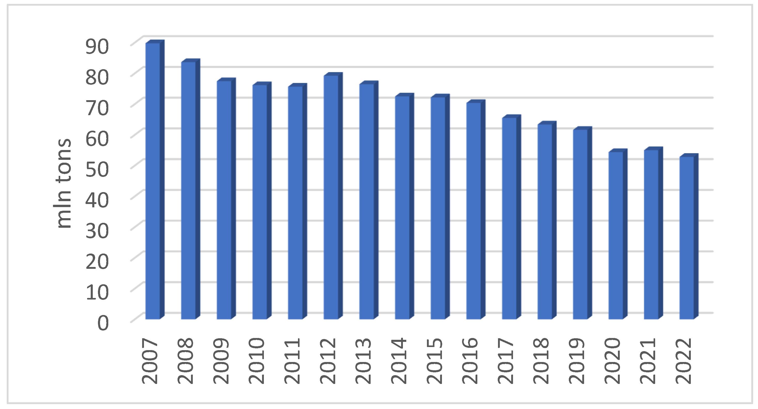
The output of hard coal in Poland continues to decline. Figure 1 shows coal production in Polish mines from 2007 to 2022 [1]. In the first part of this period, production from Polish mines covered the demand for this raw material in the country. At present, the demand for the raw material is not decreasing and the mining capacity has significantly decreased, and in 2022, it was just over 52 million tonnes, of which 40 million tonnes is thermal coal and the remaining, over 12 million tonnes, is coking coal [2].
The reduction in extraction concerns only thermal coal. This is the result of a reduction in demand for this raw material and rising extraction costs due to increasingly deep seams, as well as the legal conditions imposed on producers (CO2 emission charges).
Due to the fact that coking coal has been recognised as a strategic resource for the European Union, there are no reductions in its extraction.
The decommissioning processes only concern coal mines extracting thermal coal. In addition, there are mines for coking coal, metal ores and salt.
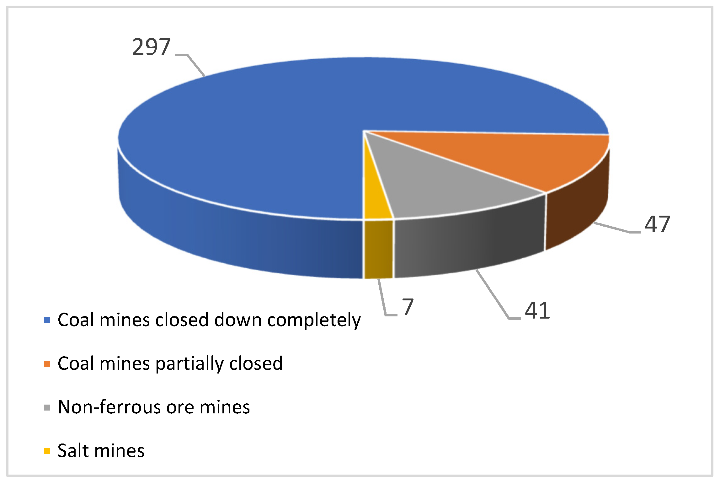
Over the last thirty years, the number of hard coal mines in Poland has decreased to 20. As reported in [3], between 1991 and 2005, the largest mine closures in European countries were carried out, which resulted in a reduction in the number of mines from 70 in 1996 to 36 in 2003, and the mining capacity was reduced by 100 million tonnes per year. It is possible to use post-mining areas as investment land, e.g., for photovoltaic farms, but these could be built virtually anywhere. Much more valuable resources are mine shafts. These are those elements of mine infrastructure that are decommissioned last, and in some cases are left to provide technical service for the neighbouring operating mines. Figure 2 shows the structure of decommissioned shafts according to the type of mine. As a result of the mine closure operation, 392 shafts were decommissioned.
Only some of the shafts of the decommissioned mines were used for further exploitation. They were converted into pumping stations in order to protect the workings of the neighbouring, active mines.
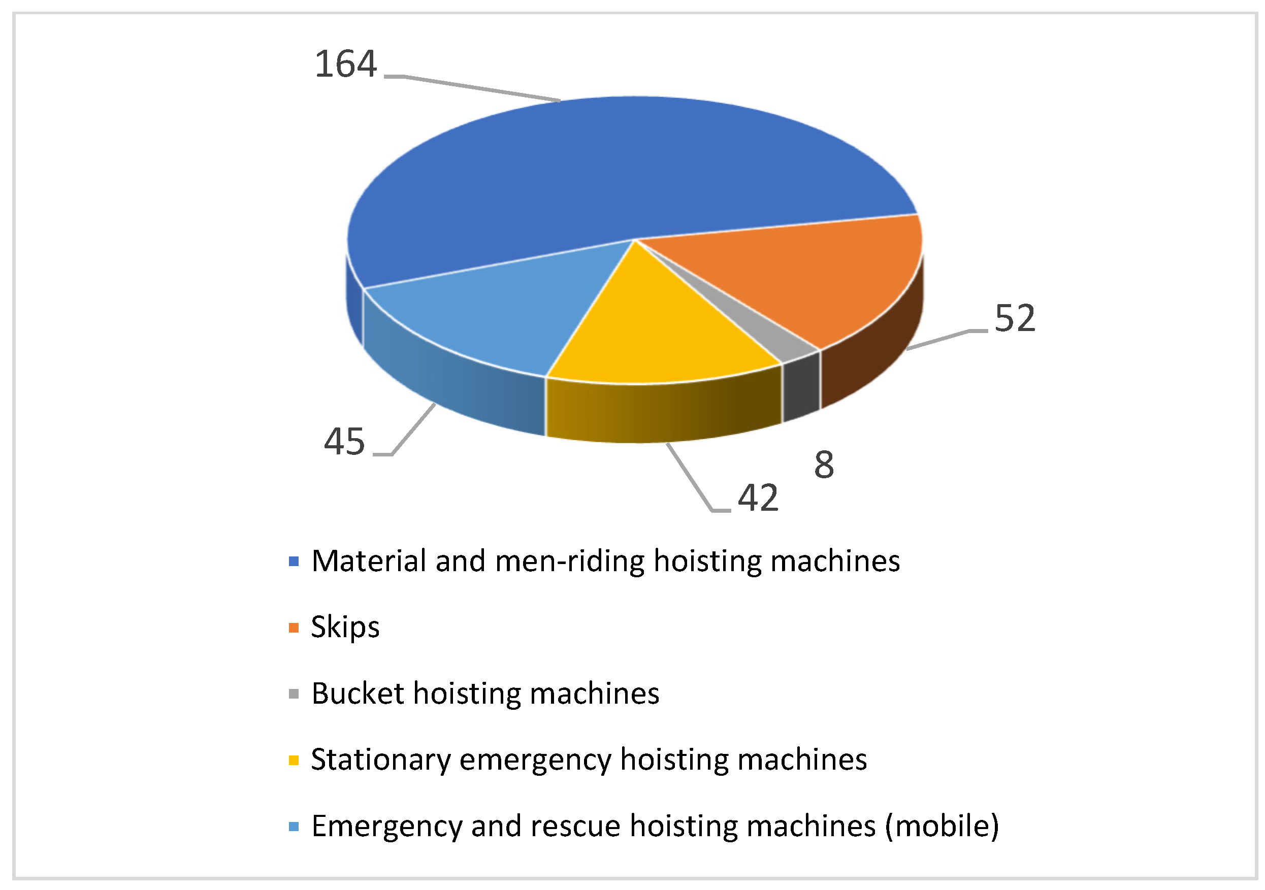
Figure 3 shows a summary of the number of mine shaft hoists, i.e., installed hoisting machines of various types in mine shafts. It should be noted that the number of mine shaft hoists does not directly correspond to the number of mine shafts, if only because there are two-compartment shafts and the emergency hoists can serve several shafts.
The process of decommissioning shafts in Poland is still progressing, so it is not possible to give a current figure for the number of active and usable shafts, for example, for energy storage.
2. Energy Storage in a Mine Shaft—Technical Possibilities
Energy storage methods have become a very important publication topic in recent years. Many centres are researching different types of solutions. Energy storage classifications vary and the latest developments in the field continue to be described [4,5,6,7].
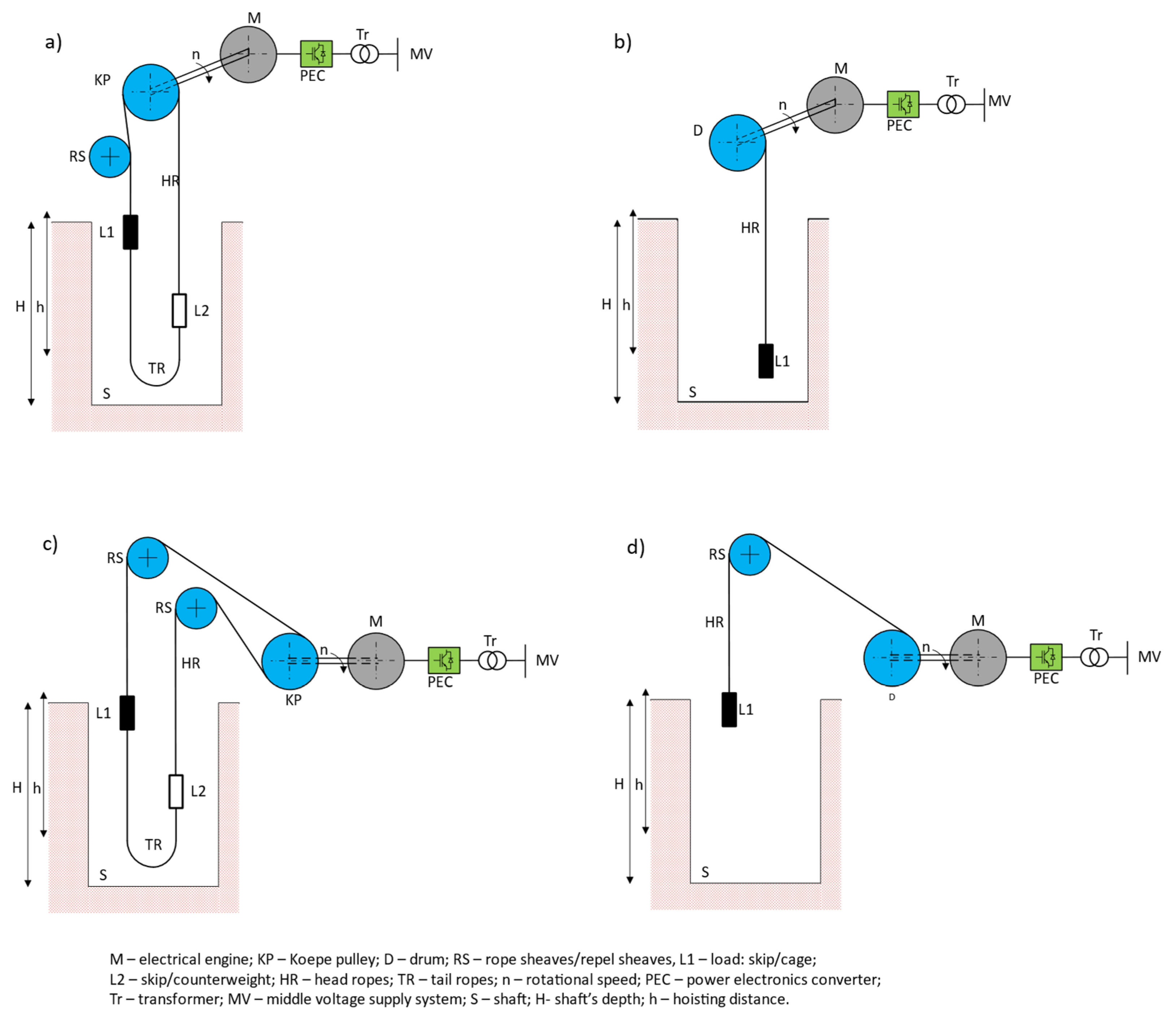
There is still little information and published results of analyses and measurements with regard to gravitational energy storage installed in mine shafts [7,8,9]. Hoisting machines implementing the process of transporting relatively large masses are built as drum machines or Koepe wheel machines. Figure 4 shows an example of the configuration of the mechanical part of a mine shaft hoisting machine.
These are the most common arrangements: a tower winder with a rope drive and motor located in the hoist tower above the shaft opening (Figure 4a,b) and a logging machine in which the motor and rope drive are located in the hoist building next to the shaft opening (Figure 4c,d). The motor and rope sheave are housed in a hoisting gear building located next to the shaft opening (Figure 4c,d). For the two options of locating the rope sheave, it is possible to design it as a Koepe pulley with the rope being wound through the sheave during the downhaul operation or as a drum from which the rope is unwound during the downhaul operation and rewound during the uphaul operation.
The basic component of the drive system is the hoisting motor. At present, DC overload motors, induction motors and slow-running synchronous motors are used. Each hoisting machine operates according to a well-defined scheme, following a corresponding drive diagram. Its shape depends on a lot of parameters, constraints and regulations. For each machine, the input movement parameters are defined, which result from the need to realise transport by the mining plant. These include:
- -
- The purpose of the hoist (transport of ore or people);
- -
- The weight of the ore/material/people to be transported;
- -
- The efficiency of the hoisting machines.
The definition of the previously mentioned parameters results in appropriate regulatory restrictions being imposed on the type of lift, which is described later in this article.
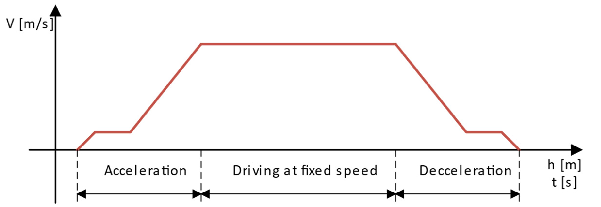
A machine designed in this way operates in a cyclic manner, with start-up (acceleration), steady-speed travel (fixed speed) and braking (deceleration) section occurring in each cycle (Figure 5).
During the downward lowering of the load, the effect which makes it possible for the implementation of gravitational energy storage occurs.
Taking this into account, it is possible to determine the conditions for which energy storage will be implemented using existing hoisting machinery, once it has been adapted to a different operating regime.
In order to test the feasibility of using a shaft hoist as a gravitational energy store, it has been assumed that the hoisting machine is designed for material transport and excavated materials weighing 12 tonnes. The travelling speed of such a hoist may vary. This is due to the regulations in force in Poland and will be a maximum of 12 m/s for driving people. For material and excavated material driving, there are no limits. For energy storage, the range of speed variation is wide and between 0.1 m/s and 20 m/s.
The potential energy of such a system results from Equation (1):
where m—load mass (assumed useful mass), g—acceleration of gravity, and h—the path of travel of the vessel.
However, it must be remembered that such a system will always operate according to a specific diagram and only some of the available energy can be used to power external equipment.
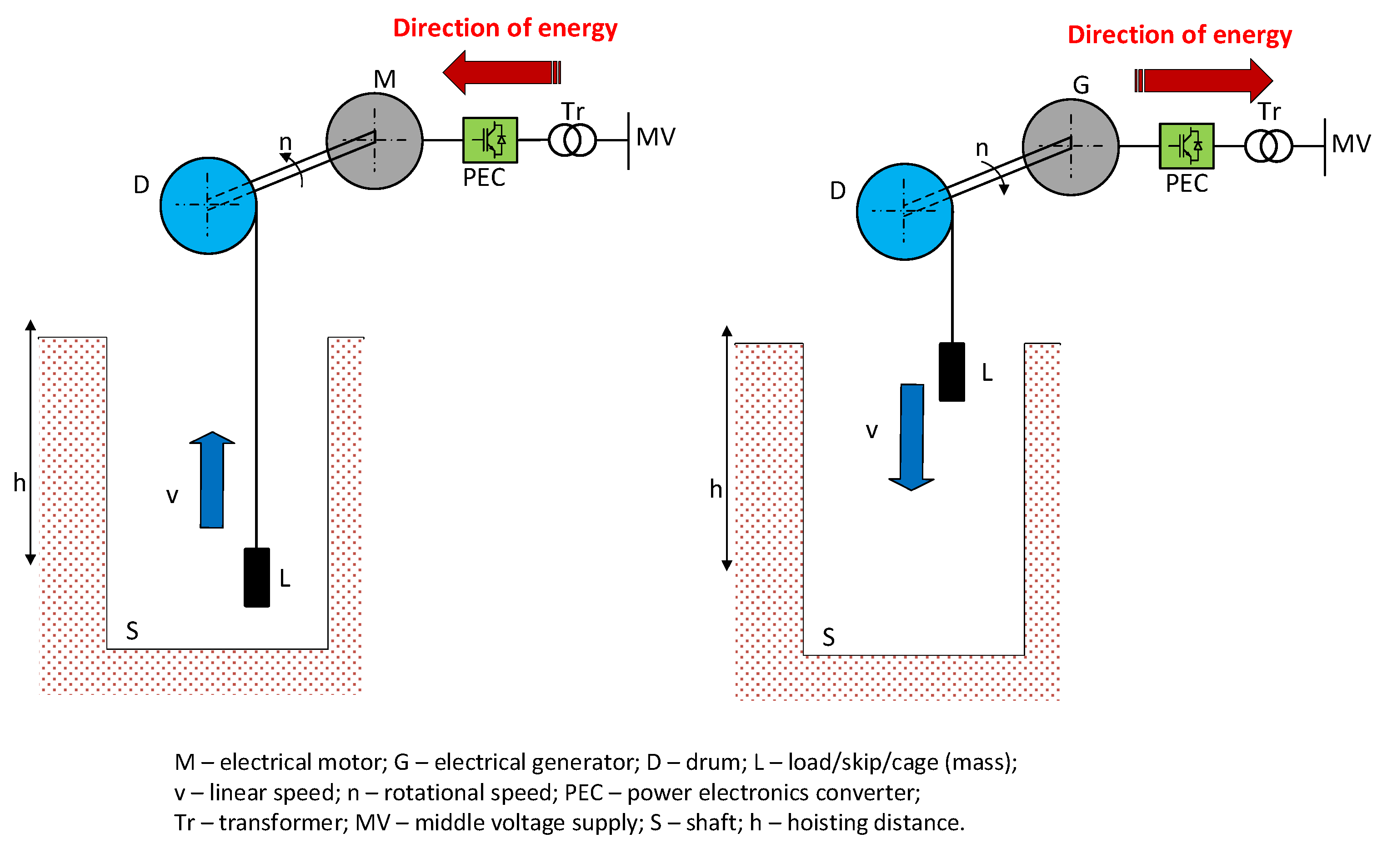
The most important part of the travel cycle is regenerative braking, where, under suitable conditions, the mechanical energy is converted into electrical energy by the hoisting engine operating in generator mode. Braking with regenerative braking is possible when the load torque is an active torque—the sign of the drag torque does not change despite a change in the direction of rotation of the motor. The second condition for regenerative braking is the maintenance of a constant flux in the machine and a constant supply voltage. In the case of a gravitational energy store, the residual torque condition is fulfilled. All that remains is to control the power electronic converter in such a way that the conditions for the constancy of the supply notch and flux are met.
In the system shown in Figure 6, another component of the drive system is the electronic power converter, which is responsible for transmitting energy with the appropriate parameters to the power grid. In hoisting machines where a separately excited DC motor is used, during generator operation of the motor, the rectifier switches to inverter operation and is responsible for adjusting the system to the grid parameters.
For the purpose of the analysis described here, power measurements were carried out on one of the hoisting machines with the following parameters:
- -
- Mass transported in the vessel: 25 Mg;
- -
- Maximum travelling speed of the vessel: 12 m/s;
- -
- Travel distance: 900 m.
The potential energy calculated according to Equation (1) is equal to 110,362 kJ, giving 30.6 kWh.
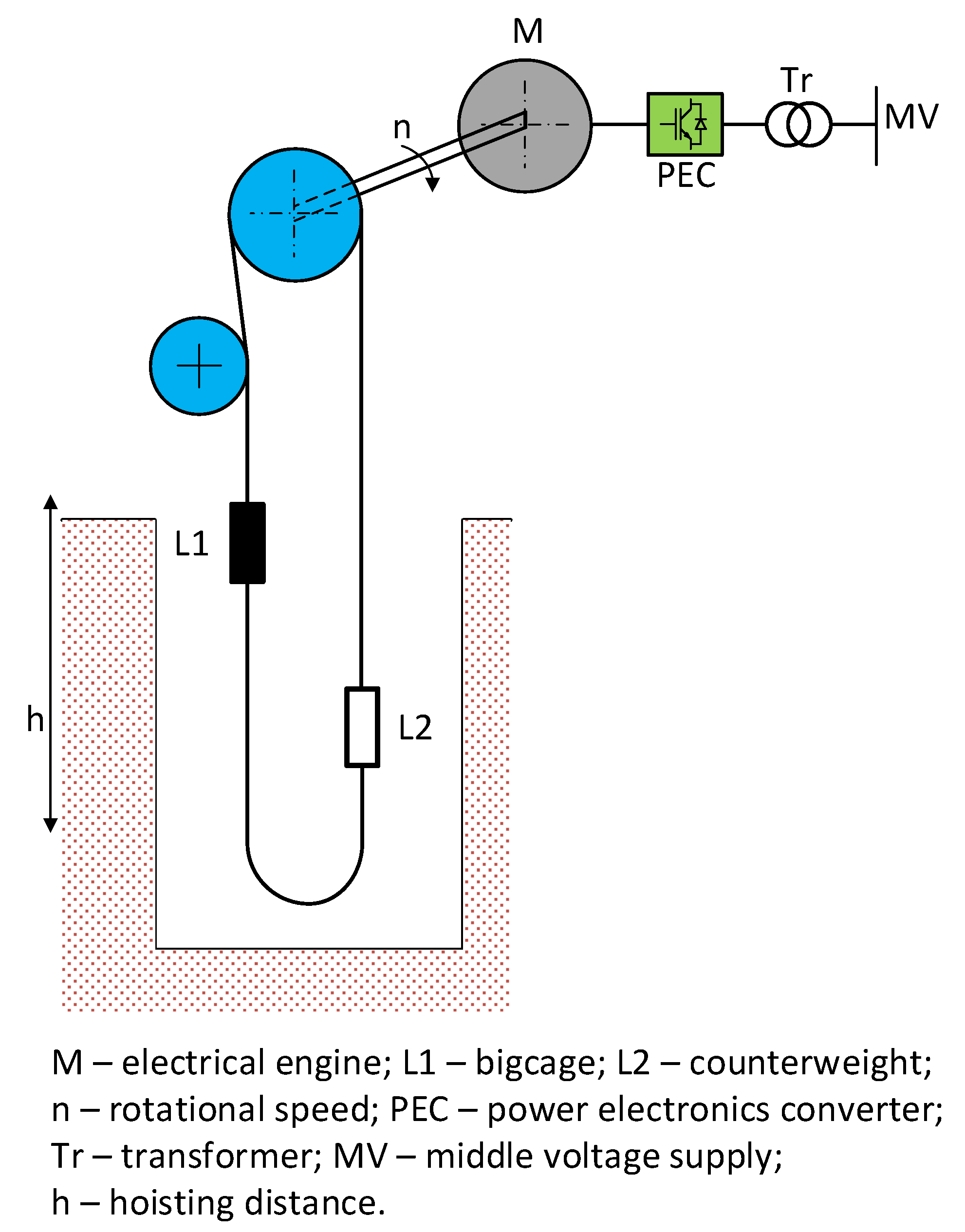
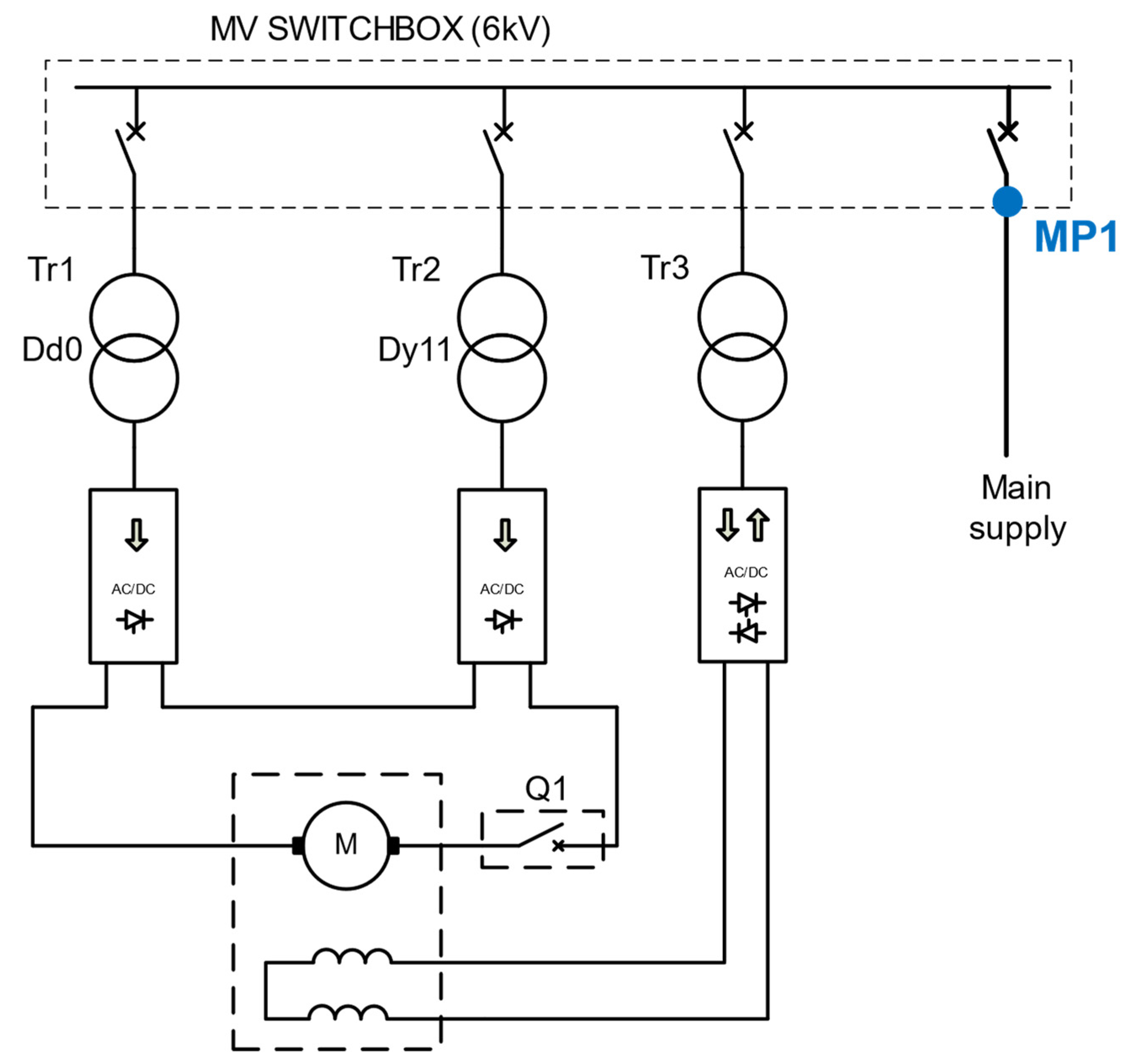
The machine was equipped with a 2.4 MW PW-124 type separately excited DC motor manufactured by a Polish factory (Figure 7). The supply voltage of the motor results from the dimensions of the Koepe pulley and the speed of the cage in the shaft (equal to 12 m/s) and is equal to 980 V. The mass placed in the counterweight is equal to 12.5 Mg. It represents the static overweight of the system, which directly affects the amount of energy stored. Measurements were taken with a Class A power quality analyser, the PQM711, in accordance with EN 50160. Current and voltage measurements were taken using current and voltage transformers placed in the field supplying the switchgear.
The measuring instrument was plugged into the supply bay of the main winder switchgear (Figure 8). The plug-in point of the instrument is marked in blue. The measurements take into account the energy consumption of all the consumers that are necessary for proper machine operation. These include: the control system, the braking system including the hydraulic power pack, the bearing lubrication system, the shaft communication and signalling system and additional auxiliary equipment.
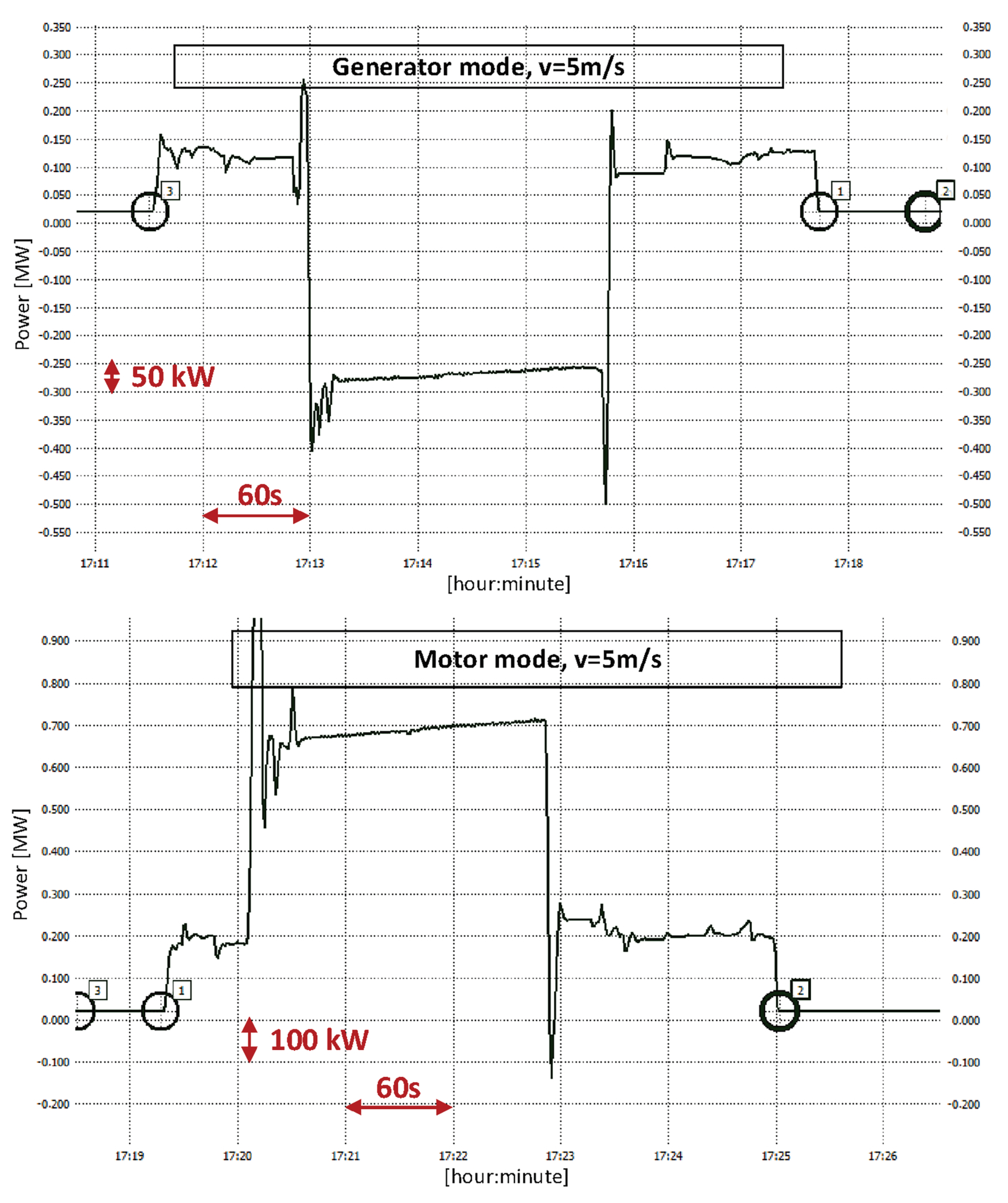
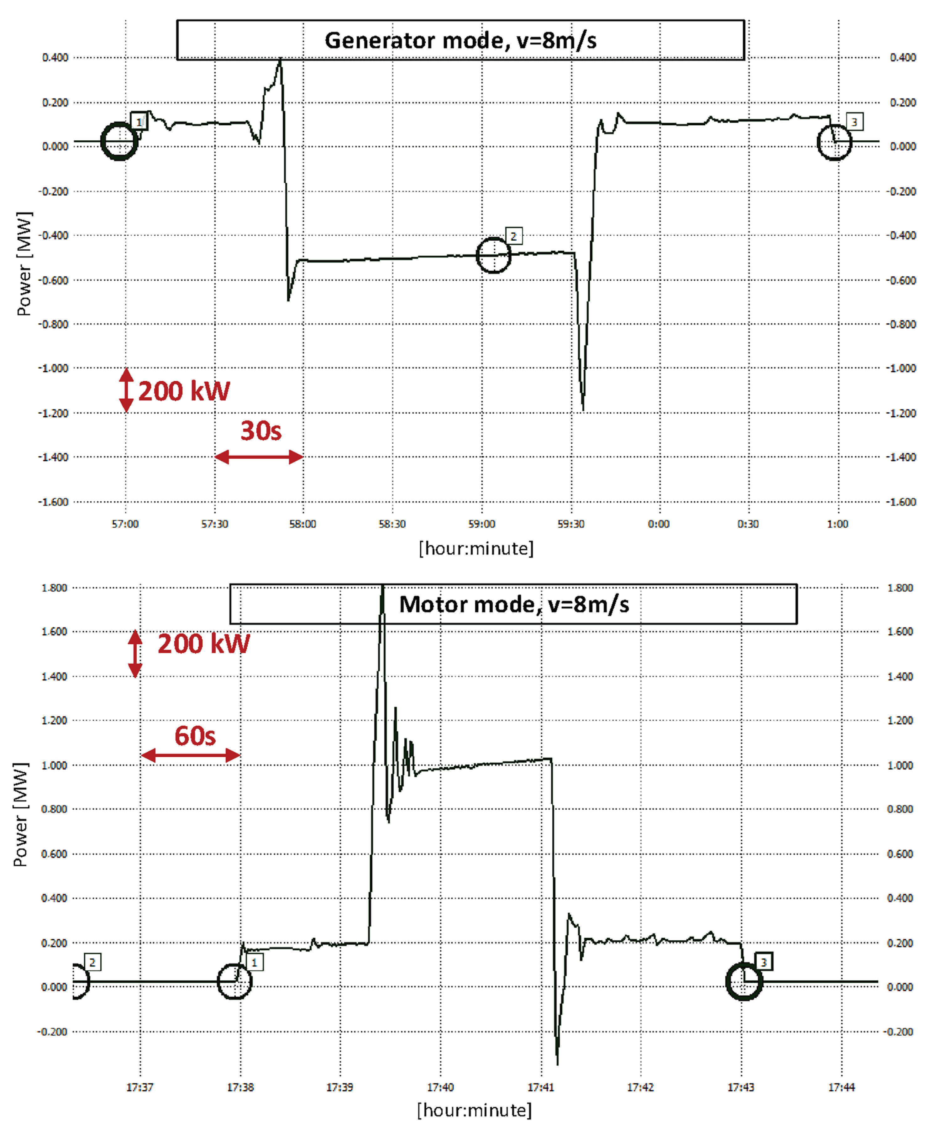
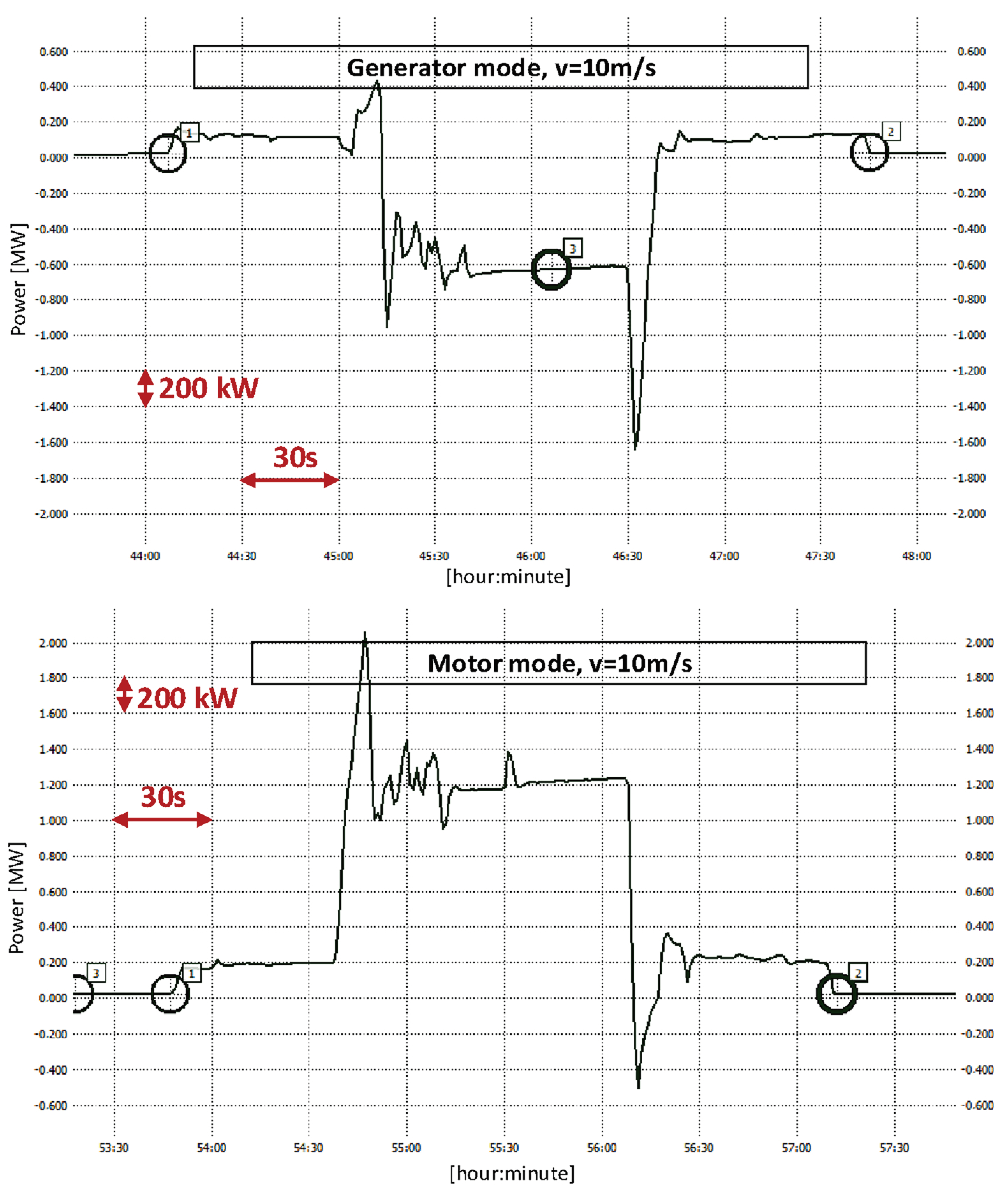
Measurements were made for three different driving speeds of the loaded vessel: 5 m/s, 8 m/s and 10 m/s (Figure 9, Figure 10 and Figure 11).
As the steady-state speed was increased, the travel time at this speed was reduced compared to the diagram with a lower steady-state speed. At 5 m/s, the steady-state travel time was about 160 s and at 10 m/s about 75 s. The power generated during steady-state travel was approximately 280 kW and 600 kW, respectively.
For each speed, a measurement was also made for the drive’s motor operation—driving with the load upwards. The length of the cycle and its individual phases did not change. However, for steady-state speed driving, the measured power for a speed of 5 m/s was about 700 kW and for a speed of 10 m/s was about 1200 kW.
It follows that the storage efficiency could be about 50%. This is not achievable in such a system due to the periods associated with the change in acceleration.
In this case, the efficiency calculation has been limited to the steady-state travel period. This is justified because the acceleration and deceleration times of the hoisting machine are long in relation to the steady-state travel period. If the hoisting machine is used as an energy storage system, the travel speed should be considerably lower, so the acceleration and deceleration times will also be shorter. Calculations were made for the machine operation described earlier, taking into account the transients in the machine operation, i.e., the acceleration and deceleration periods. When the cage was travelling at a speed of 8 m/s, the storage efficiency was 47.8%.
However, the calculation of efficiency is a much more serious problem that needs a case-by-case-based approach due to the differences that exist between each mine hoist, if only because of the geometrical dimensions of the shaft [10].
3. Energy Storage in a Mine Shaft—Legal Regulations in Poland
According to the Polish Geological and Mining Law [11], an excavation is a space in the ground property or rock mass resulting from mining works. A shaft is a vertical or inclined mine working at an angle of inclination greater than 45° [12]. As such, it is subject to all regulations applicable to such a pit. The installation, operation and dismantling of the equipment may be carried out in accordance with the rules clearly set out in the regulations.
A mine shaft hoist, and this will be the gravitational energy storage system, must be constructed and operated based on:
The first of the aforementioned regulations specifies which elements of mine shaft lifts are subject to the so-called authorisation procedure for use in underground mines. The procedure is carried out on the basis of documentation for the equipment in question and confirmation that the requirements have been met is given by the President of the State Mining Authority. The mine shaft hoist components that are subject to this procedure are: hoisting machinery, hoisting vessels, rope sheaves, suspensions for hoisting ropes, compensating ropes, guide ropes and buffer ropes, suspensions for vessels, and shaft signalling and communication equipment. It follows that any element of the gravitational energy storage will be subjected to this procedure.
The second regulation defines the conditions for the operation of equipment installed in a mine shaft. Each piece of equipment is subjected to strict inspection procedures during its period of operation. Reviews, inspections and tests are carried out by the operators of the equipment, the mine’s traffic experts and the mining supervisory authorities, respectively. Vertical transport equipment belongs to the group of basic equipment. The resulting gravitational energy storage facility will also be a transport facility and its operation will be carried out in accordance with the described regulations. If an existing winding machine is used as an energy store, documentation must be prepared for it with the relevant modifications and the relevant permissions must be obtained. Therefore, when designing the energy storage in the shaft, considerations must be taken whether its design will allow for the relevant inspections and tests to be carried out during its operation, if only by allowing access to the shaft for inspectors.
The regulations described earlier relate to the construction of the storage in the mechanical-electrical part as a device in the mine workings. The second issue is the operation of energy storage in the power system. At present, regulations concerning energy storage facilities are in force in Poland, in particular the Energy Law, which has been amended in this context [15], and they define the rules for integrating an energy storage facility into the power grid.
4. Energy Storage in a Mine Shaft—The Economic Aspect
The amount of energy stored in a gravity energy store depends on the size of the load that is suspended and the height to which the mass is lifted. Research is currently being carried out into making gravity storage using concrete blocks stacked into a single tall structure as the load [16], as well as using a mine shaft for storage [17]. This article is concerned with the latter type of storage, which undoubtedly requires significantly more investment if the calculations were to be carried out in conjunction with the excavation of a new shaft. However, it should be borne in mind that currently in Poland a significant number of mining facilities are undergoing decommissioning processes. This means that it is possible to use the existing infrastructure for energy storage. It should be noted, however, that the primary cost of storage in such a case will be to equip the shaft with a high-efficiency drive which will enable increased storage efficiency. In addition, the cost of operating the shaft and the equipment will be significant. The calculation of the real costs must be performed on a case-by-case basis [18,19].
The following items should be included in the economic calculation:
- The costs of adapting the shaft to the new operating conditions (shaft reinforcement, vessel/vessel guidance);
- The costs of fitting/upgrading the new high-performance drive equipment;
- The costs of maintaining the crew to operate the shaft—people with the appropriate qualifications and the structure of the mining company;
- The costs of expert surveys;
- The costs of revisions, inspections and service maintenance.
Additional costs arising from specific conditions in the mine shafts being decommissioned must still be taken into account. If it is necessary to pump out incoming water from the workings of a mine undergoing decommissioning because of the risk of flooding in neighbouring mines, the cost of such activities will not be included in the cost of maintaining the energy storage system.
If, however, the store would be operated in a shaft that no longer fulfils any additional functions, the cost of maintaining the water level in the shaft at an appropriate level, e.g., by means of depth pumps, should be included in the calculation.
In addition to the costs already mentioned, mention should be made of those associated with connecting the storage facility to the distribution network, depending on the size of the storage facility.
5. Conclusions
The problem of energy storage is one of the most vital challenges, the successful solution of which will make an important contribution to the further development of civilisation. The energy transition, the full use of renewable energy sources and the elimination of fossil fuels, will depend in large part on whether energy can be stored effectively. As we can see, on the one hand, the closure of one industry creates opportunities for the development of a new one. This is the case here, where the decommissioning of mines opens up opportunities to store energy in elements of its infrastructure. Gravitational energy storage is feasible, as the results of measurements show, but the preparation of a system that will work in a responsible manner is complicated and is an interdisciplinary issue.
According to the systems reliability theory, in order to calculate the efficiency of equipment consisting of multiple components, the structure of the system must be established, and then the resulting efficiency of such a set of equipment must be calculated. In the case of a hoisting machine, the approach that the storage efficiency is most and only influenced by the efficiency of the motor is false. If it were, the efficiency of energy storage in the form of potential energy would be very high, at over 90%. As measurements prove, the efficiency of this storage is much lower. All components of a mine shaft hoist must be taken into account, as this is also the case with energy storage.
At present, the use of most hoisting machinery in mines is relatively low. It is approximately 40–50% of the available time. This means that storing energy in such shafts can improve a mine’s bottom line by increasing the machine’s uptime. However, this requires changes in both legal and technical/organisational regulations.
Funding
This research received no external funding.
Data Availability Statement
The data presented in this study are available on request from the corresponding author. The data are not publicly available due to contractual restrictions on measurements.
Conflicts of Interest
The authors declare no conflict of interest.
References
- Available online: www.polskirynekwegla.pl/raporty-dynamiczne (accessed on 11 April 2023).
- Kicki, J. Górnictwo Węgla Kamiennego w Polsce; Raport 2021; Mineral and Energy Economy Research Institute, Polish Academy of Science: Krakow, Poland, 2022. [Google Scholar]
- Czaja, P. Ocena rozwiązań projektowych likwidacji szybów zastosowanych w procesie restrukturyzacji polskiego górnictwa węglowego. AGH J. Min. Geoengin. 2009, 33, 105–119. [Google Scholar]
- Aneke, M.; Wang, M. Energy storage technologies and real life applications—A state of the art review. Appl. Energy 2016, 179, 350–377. [Google Scholar] [CrossRef] [Green Version]
- Berrada, A.; Emrani, A.; Ameur, A. Life-cycle assesment of gravity Energy storage systems for large-scale application. J. Energy Storage 2021, 40, 102825. [Google Scholar] [CrossRef]
- Al-Hilfi, L.M.A.; Morris, S.; Fathima, A.P.; Ezra, M. Investigation of Potential Benefits and Challenges of Using Gravity Energy Storage in Residential Sectors. In Proceedings of the International Virtual Conference on Power Engineering Computing and Control: Developments in Electric Vehicles and Energy Sector for Sustainable Future (PECCON), Virtual, 5–6 May 2022. [Google Scholar]
- Tong, W.; Lu, Z.; Chen, W.; Han, M.; Zhao, G.; Wang, X.; Deng, Z. Solid gravity Energy storage: A review. J. Energy Storage 2022, 53, 105226. [Google Scholar] [CrossRef]
- Chaturvedi, D.K.; Yadav, S.; Srivastava, T.; Kumari, T. Electricity storage system: A Gravity Battery. In Proceedings of the 2020 Fourth World Conference on Smart Trends in Systems, Security and Sustainability (WorldS4), London, UK, 27–28 July 2020. [Google Scholar]
- Rufer, A. Design and Control of a KE (Kinetic Energy)—Compensated Gravitational Energy Storage System. In Proceedings of the EPE’20 ECCE Europe, Lyon, France, 7–11 September 2020; ISBN 978-9-0758-1536-8. [Google Scholar]
- Vlahopoulos, D.; Bouhouras, A.S. Performance Evaluation of Electrical Energy Storage Systems Focused on Gravity Storage Technology. In Proceedings of the 2nd International Conference on Energy Transition in the Mediterranean Area (SyNERGY MED), Thessaloniki, Greece, 17–19 October 2022. [Google Scholar]
- Polish Geological and Mining Law; Act of 9 June 2011; State Mining Authority: Katowice, Poland, 2011.
- Kostrz, J. Głębienie Szybów; XXII School of Underground Mining: Krakow, Poland, 2013. [Google Scholar]
- Regulation of the Council of Ministers of 30 April 2004 on the Authorisation of Products for Use in Mining Plants; Warszawa, Poland, 2004.
- Regulation of the Minister of Energy of 23 November 2016 on Detailed Requirements for the Conducting Underground Mining Works; Warszawa, Poland, 2016.
- Available online: www.ure.gov.pl (accessed on 8 April 2023).
- Available online: www.energyvault.com (accessed on 16 March 2023).
- Available online: www.gravitricity.com (accessed on 21 March 2023).
- Morstyn, T.; Chilcott, M.; McCulloch, D. Gravity Energy storage with suspended weights for abandoned mione shafts. Appl. Energy 2019, 239, 201–206. [Google Scholar] [CrossRef]
- Schmidt, O. Levelized Cost of Storage. Gravity Storage; Heindl Energy GmbH: Stuttgart, Germany, 15 October 2018; Available online: https://heindl-energy.com/wp-content/uploads/2018/10/LCOS_GravityStorage-II-Okt-2018.pdf (accessed on 21 March 2023).
Figure 1.
Coal production in Poland.

Figure 2.
Number of decommissioned shafts.

Figure 3.
Number of hoisting machines.

Figure 4.
The type of hoisting machines: (a) tower mounted, Koepe pulley; (b) tower mounted, drum; (c) floor mounted, Koepe pulley; (d) floor mounted, drum.
Figure 4.
The type of hoisting machines: (a) tower mounted, Koepe pulley; (b) tower mounted, drum; (c) floor mounted, Koepe pulley; (d) floor mounted, drum.

Figure 5.
Hoisting diagram.

Figure 6.
Energy conversion in gravitational energy storage.

Figure 7.
The kinematic diagram and the power supply of the winder under test.

Figure 8.
Place of the power quality analyser (marked MP1).

Figure 9.
Driving diagrams for generator and motor operation (speed of the load in the shaft: 5 m/s).
Figure 9.
Driving diagrams for generator and motor operation (speed of the load in the shaft: 5 m/s).

Figure 10.
Driving diagrams for generator and motor operation (speed of the load in the shaft: 8 m/s).
Figure 10.
Driving diagrams for generator and motor operation (speed of the load in the shaft: 8 m/s).

Figure 11.
Driving diagrams for generator and motor operation (speed of the load in the shaft: 10 m/s).
Figure 11.
Driving diagrams for generator and motor operation (speed of the load in the shaft: 10 m/s).

Disclaimer/Publisher’s Note: The statements, opinions and data contained in all publications are solely those of the individual author(s) and contributor(s) and not of MDPI and/or the editor(s). MDPI and/or the editor(s) disclaim responsibility for any injury to people or property resulting from any ideas, methods, instructions or products referred to in the content. |
© 2023 by the author. Licensee MDPI, Basel, Switzerland. This article is an open access article distributed under the terms and conditions of the Creative Commons Attribution (CC BY) license (https://creativecommons.org/licenses/by/4.0/).
Share and Cite
MDPI and ACS Style
Siostrzonek, T. The Mine Shaft Energy Storage System—Implementation Threats and Opportunities. Energies 2023, 16, 5615. https://doi.org/10.3390/en16155615
AMA Style
Siostrzonek T. The Mine Shaft Energy Storage System—Implementation Threats and Opportunities. Energies. 2023; 16(15):5615. https://doi.org/10.3390/en16155615
Chicago/Turabian StyleSiostrzonek, Tomasz. 2023. "The Mine Shaft Energy Storage System—Implementation Threats and Opportunities" Energies 16, no. 15: 5615. https://doi.org/10.3390/en16155615
Note that from the first issue of 2016, this journal uses article numbers instead of page numbers. See further details here.