1. Introduction
Electric motors and generators are critical to modern life. They have been incorporated into every aspect of our lives, and the need for this technology grows every year. Their installations are found wherever humans have sent technology and are integrated into almost every human settlement and vehicle. The power industry and the mining industry continue to employ large electrical motors and generators. They are also becoming standard equipment in large ships, submarines, and unmanned surface and underwater vessels, with a focus on high reliability and long mission endurance.
Electrical motors have a reasonably high level of efficiency, varying from 78.8% for small motors to over 92.4% for large motors due to their superior magnetic flux geometry [
1]. However, any improvements in efficiency and reliability will benefit current end users and new areas such as electric cars and electrical aircraft, including unmanned aerial vehicles.
Electrical machine efficiency losses comprise iron losses, copper losses, rotor losses, stray losses, and friction and windage losses. These losses, which for a typical 15 kW motor at full load, amount to 1 kW, are made up of 60 W friction and windage, 200 W core losses, 500 W stator losses, 180 W rotor losses, and 60 W stray losses. These losses are directly converted to heat, and this heat affects the mechanical components, such as the bearing, bracing and wedging systems [
2,
3], and, critically, the electrical insulation systems [
4].
In addition, motor operating environments are constantly changing from normal (seasonal) climatic changes to extreme temperature changes due to operational environments, as found in smelters and transportable packages such as compressor stations or cooling modules, which tend to be used in quick-install and set-up situations and are normally exposed to environmental conditions, including full sun.
Therefore, the heat generated in volume, which is naturally dispersed by surfaces, is both a crucial design factor and a significant design limitation for electric motors [
5]. As motors become larger, special solutions are needed to remove internal heat caused by losses, such as using an internal heat exchanger, hydrogen environments, and water-cooled windings [
6]. For electrical machines that are predominantly online and loaded, such as air-circulating fan systems, running temperatures are relatively stable; these machines are not significantly affected by differential thermal expansion and contraction and have relatively long operational lives. For motors that have operational start and stop routines, such as pump pressurizing systems, thermal cycling is a regular part of the operating cycle, and these machines suffer from mechanical fatigue and insulation failure due to mechanical and thermal stresses.
1.1. Electrical Insulation
The electrical insulation in electrical motors and generators is especially vulnerable to high temperatures and mechanical stress. High temperatures are the most prevalent cause of insulation failure, which is a complete electrical breakdown of the insulation. Because of the wide range of temperatures, operating conditions, and insulation costs, insulation classes have been developed (
Table 1) [
7,
8]. In the USA, the nominal winding class used is class B, and to help provide a better temperature tolerance, a motor design requirement will often specify class B materials with a class E temperature rise. In Europe and Australia, the nominal insulation system is class F.
Insulation temperatures that exceed class temperature affect insulation life. From graphs published by ESSA [
9] showing insulation class and expected life versus temperature, Equation (
1) can be derived. The calculation of insulation life for class F’s maximum temperature can be seen in Equation (
2), and the calculation of the insulation life if the temperature is raised 10 °C can be seen in Equation (
3).
The expected insulation life in hours (Equation (
1)) = antilog value of Y, where
and C = 9.8021 for Class H, 9.1543 for Class F, 8.3549 fr Class B and 7.6005 for Class A.
For instance, for class F insulation at T = 105 °C,
and for class F insulation at T = 115 °C,
The presence of temperatures 10 °C over class temperature reduces insulation life by
This 10 °C over temperature can approximately half insulation life, as calculated in Equation (
4). A rule of thumb in industry [
9] is that, for every 10 °C increase in temperature, insulation life is halved.
The motor’s operating temperature is the combination of the remaining internal heat plus the ambient temperature, as seen in Equation (
5). The cooler the ambient temperature (the nominal motor environment), the greater the heat extraction from the housing, and therefore, the cooler the insulation.
Lowering the ambient temperature for standard induction motors will significantly improve motor running temperatures, but this approach is not suitable for large drives with wound rotors, slip rings, brushes, and starting resistors. These machines require several factors to be correct to allow a patina to develop between the brush and the slip ring, reducing brush friction and contact resistance [
8]. These factors include temperature, current density, humidity, and brush composition. One of the key requirements is temperature. For correct commutation, the slip rings need to be at approximately 100 °C, so cooling the whole environment affects commutation, resulting in high brush and slip ring wear and very high maintenance costs.
Another factor that causes electrical insulation failure is moisture absorption, and the most common cause is internal condensation. Because of the mass of the core and windings, there is a time lag between the motor temperature and the external daily temperature changes. Depending on the difference between humidity and temperature, the dew point can be reached, resulting in moisture condensing on the internal surfaces, contaminating windings and affecting their insulation properties.
This can happen in any location, indoors or outdoors. Being outside with greater exposure to the elements can significantly increase the problem. Because of the mass of a motor, there is a temperature equalization lag, as daily temperatures tend to start cold and warm up quickly.
1.2. Motor Heat Extraction Systems
As mentioned earlier, because of their inefficiencies, electrical motors generate internal heat. This heat is generated in volume but is dissipated by surfaces. As motors become larger, the ability to be rid of this heat via surfaces becomes increasingly difficult. As pointed out by Walker [
10], motor design is fundamentally a process of compromise, and heat caused by losses becomes a major limitation.
A simple and effective cooling method is simply a ventilated or open-ended motor with an internal fan blowing air through the machine [
11]. Being open with exposed windings has severe limitations, but this arrangement is low-cost and allows a small frame size.
To provide better internal protection, the most common motor arrangement is a totally enclosed motor, where heat dissipation occurs via simple conductive cooling. To improve the basic conductive cooling arrangement, an external fan and cowling are employed to blow air over the outer housing, improving the heat dissipation and allowing motors to be smaller or have increased output (kW) with the same size machine frame [
12]. This is the most common type of motor and is designated as a totally enclosed fan-cooled (TEFC) motor. The addition of ribbed outer housings will further improve a machine’s capability in removing unwanted heat [
13].
For large machines, conduction cooling systems become less effective, and heat exchangers are normally employed, enabling smaller motor frames to be employed; however, manufacturing and service costs are greatly increased [
11].
Standard cooling systems for motors can be grouped as follows:
- 1.
Conductive;
- 2.
Conductive with external fans;
- 3.
Conductive with internal and external fans;
- 4.
Air heat exchangers (internal air to external air);
- 5.
Water heat exchangers (internal air to water heat exchangers).
1.3. Thermoelectric Coolers/Heaters (Peltier Devices)
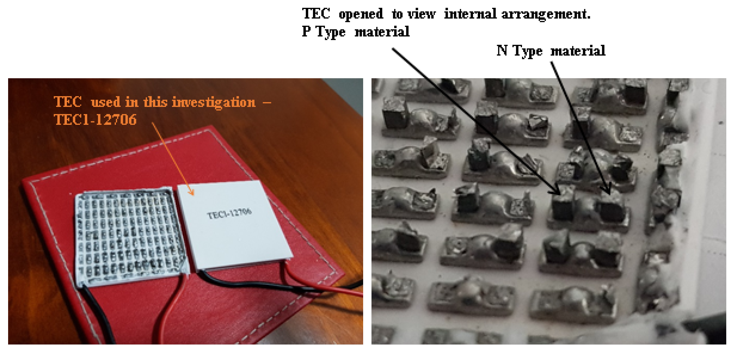
Thermoelectric coolers/heaters (TECs) are constructed from a combination of N- and P-type material between two plates, which are normally ceramic or, more recently, copper, as shown in
Figure 1.
These devices have two application configurations, as follows: (1) when a voltage is applied across the TEC, a current flows through the TEC, causing one plate to become hot and the other to become cold thus transporting heat from one plate to the other. This is known as the Peltier effect. By reversing the power supply’s polarity, the heat can be pumped in the opposite direction. (2) If a temperature difference is developed across the TEC (such that one plate is hot and the other is cold), a voltage will develop across its terminals, and this is known as the Seebeck effect. There are a variety of TECs on the market that range in current and thermal capability; their associated costs reflect their capabilities (
Table 2).
TECs could originally be found in small portable eskies, with a switch enabling them to keep food hot or cold. Today, they are found in drink fountains and car sets as heaters and coolers. They have also been used in remote locations to charge batteries. TEC modules have a small footprint (40 × 40 × 3 mm) and can easily be combined with various heat transfer systems to improve performance. Because of their successful applications, they are slowly being tried in new applications and research. This has supported an increase in available TEC current and thermal capacities (
Table 2), and they can easily be purchased online.
1.4. Scope and Contributions
All components of electrical motors are affected by temperature, and high temperatures directly impact insulation life. Thermal variations result in differing thermal expansions and contractions of the cores, insulation, and conductors, affecting the winding insulation and the wedging and bracing systems. The need for the thermal management of electrical motors is a result of their geometry and construction. Thermal management, the ability to remove unwanted heat and maintain temperatures within insulation class limits, is a major constraint for motor manufacturers. Thermal management is generally an active/passive process, involving internal fan designs circulating internal air and conducting generated heat to the motor housings, which have a variety of cooling system arrangements from smooth outer circumferences to external ribs and fans for cooling. The larger the machine, the more complex and costly the cooling systems, and the greater the cooling system service costs. Each manufacturer has their own various cooling systems, and these are designed to match the size of the motor. Manufacturers continue to look for ways to compete in the market, and cooling arrangements and associated service requirements continue to change as new systems are tried, implemented, and marketed.
In all cases, the cooling systems listed in
Section 1.2 are passive systems and rely on surface areas, air flow, and heat extraction in large motors to remove unwanted heat. The possible introduction of thermoelectric coolers/heaters (TECs), which are comparatively cheaper, adds an active control cooling element to the heat extraction system. As an active system, they provide the ability to control how much assistance they can provide to the cooling system to extract heat and also have the ability to pump heat into a machine, raising temperatures, reducing thermal stress, and eliminating moisture issues. The possible addition of TECs to assist in thermal control has not previously been researched, and here, we explore the TEC’s ability to maintain a constant core temperature in an environment with wide temperature variations.
This research investigates the application of TECs and their ability to stabilize winding temperatures. The hypothesis for this research is that TECs can pump heat into and out of a motor, minimizing the change in winding temperatures at various loads and external conditions, helping to reduce thermal cycling stresses and eliminate condensation issues.
The remainder of the paper is as follows:
Section 2 explains the methodology and experimental setup.
Section 3 explains the data collection process.
Section 4 summarizes the results from the experiments carried out.
Section 5 discusses the obtained results, and
Section 6 concludes with the findings of the study.
2. Experimental Setup
In our previous studies, we explored the ability of TECs to heat a core and its windings when a motor is de-energized [
6,
14], as well as their ability to remove heat when running at full load [
15,
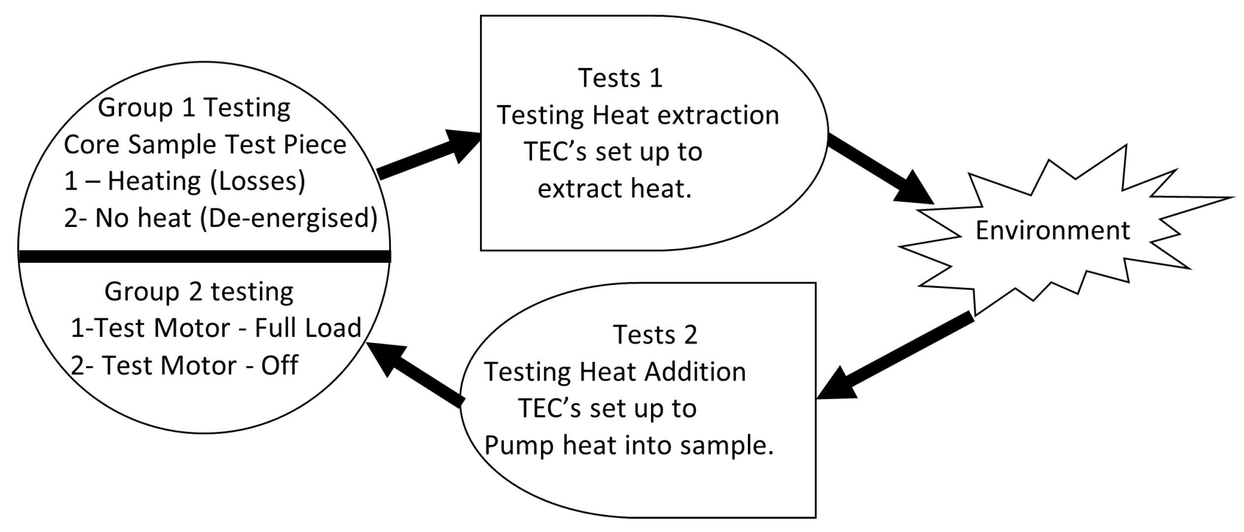
16]. Our methodology was to establish the performance capability of TECs to add or extract heat from a core test sample by measuring temperatures at various locations. The measurements focused on the slot position that holds the windings. Measurements were taken using temperature differences (equating to losses) with various TEC currents and setups to gauge application conditions; then, these systems were applied to a test motor to examine TEC performance, as mapped out in
Figure 2.
The thermoelectric cooler (Peltier module) chosen for this project is the TEC1-12706. These units are inexpensive (A
$3.21 per module) and have a 57 W heating/cooling (dependent on current direction) capability at nominally 6 A (see
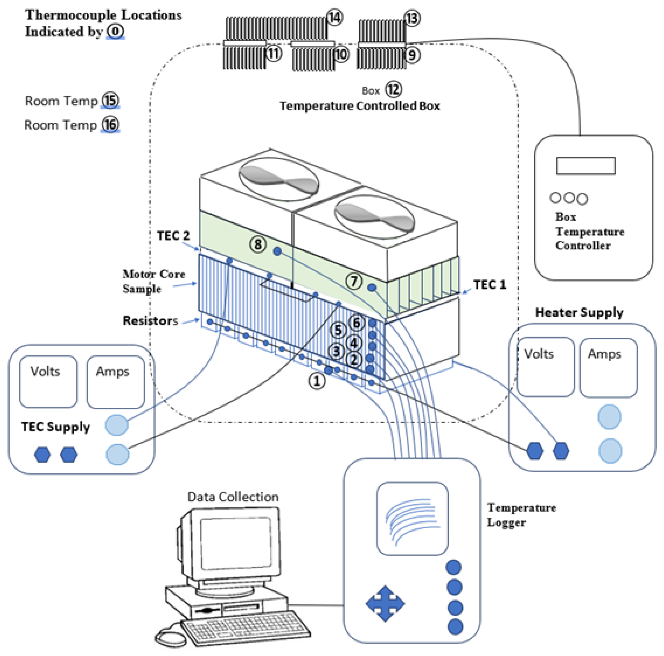
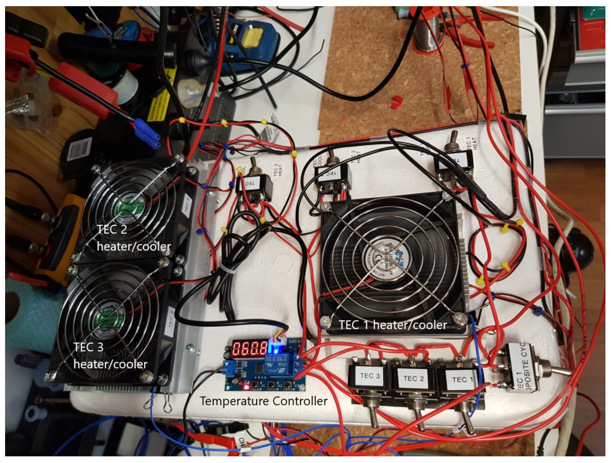
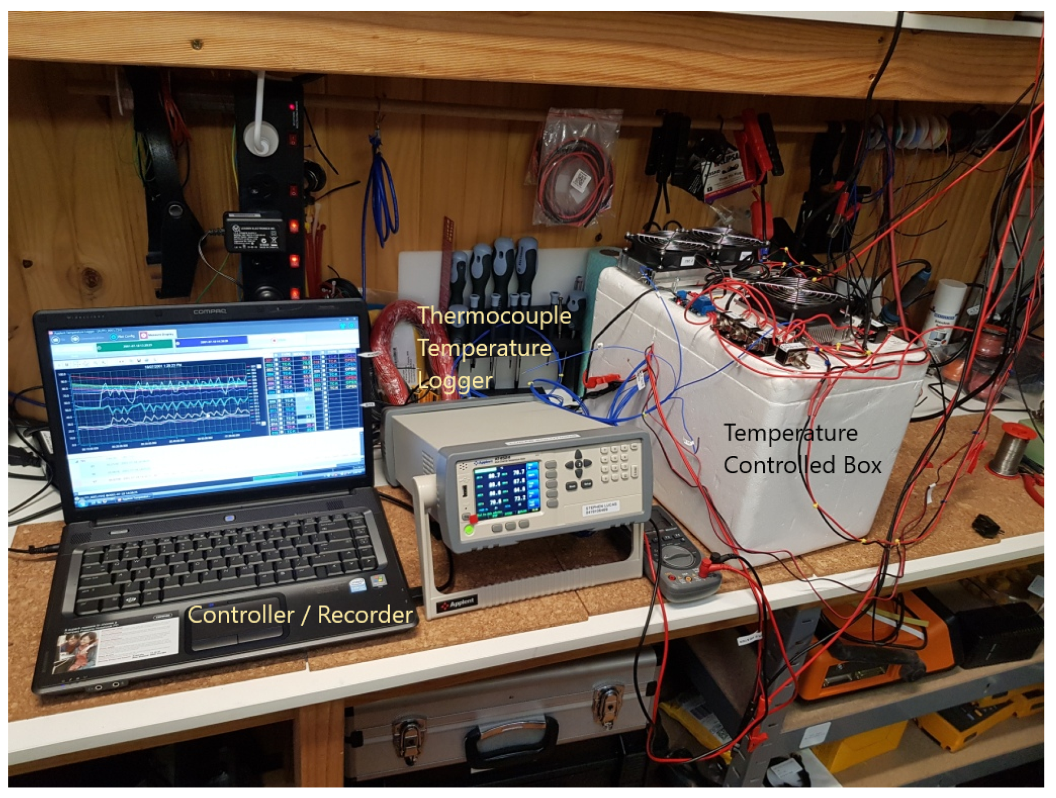
Table 2). In this study, we established a test configuration, as shown in
Figure 3, and explored the capabilities of the TEC to add heat and remove heat from a core in various environmental conditions and thus provide thermal control. A temperature-controlled box, as shown in
Figure 4 and
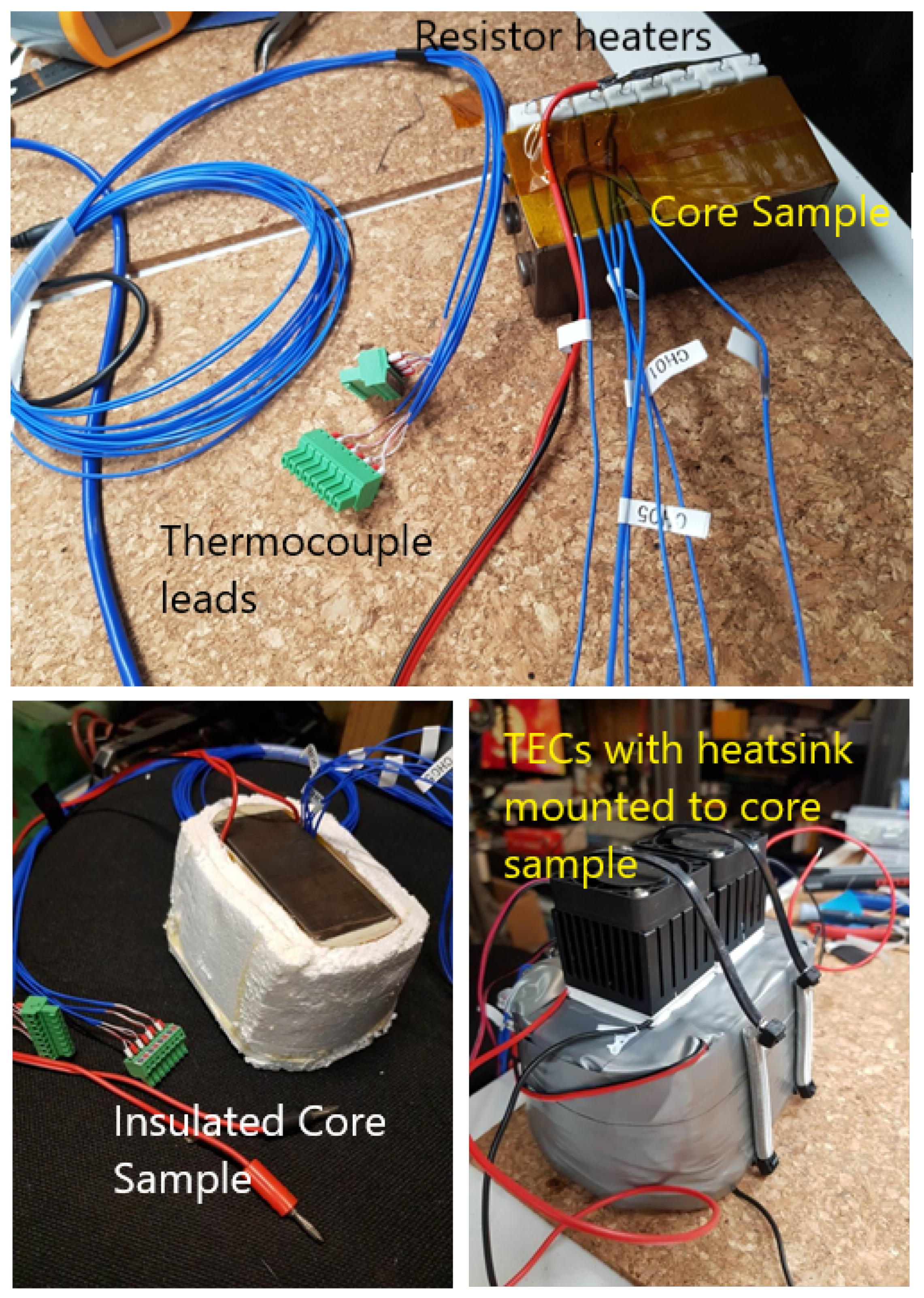
Figure 5, and a new test core sample, as shown in
Figure 6, were constructed to investigate the TEC’s capability to assist cooling/heating at different environmental temperatures.
3. Data Collection
3.1. Heating Test
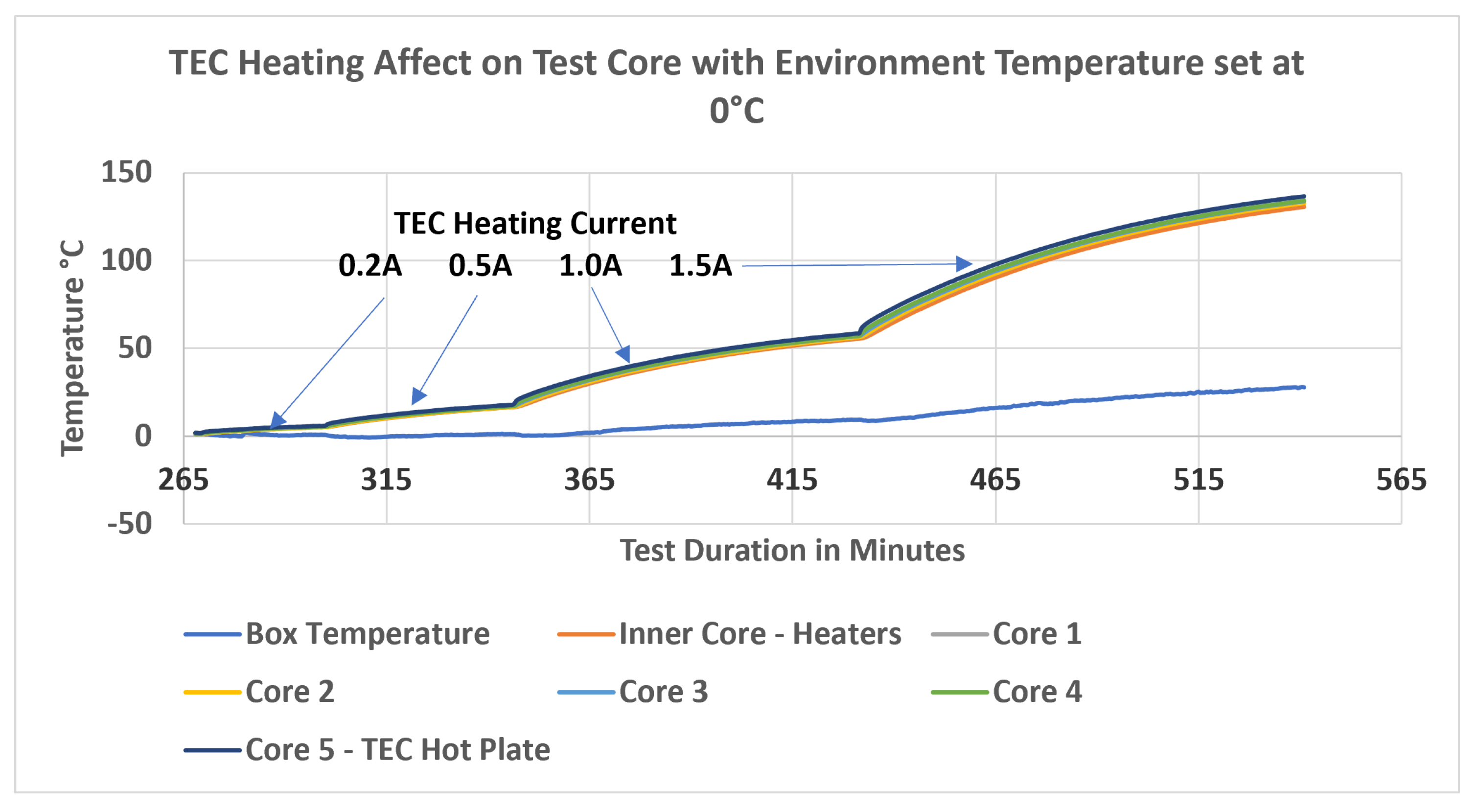
This set of tests aimed to measure the rate of the increase in temperature of the test sample with different TEC currents in a 0 °C degree environment. The thermal control box was set to 0 °C, and the core test sample was allowed to stabilize at 0 °C. The TEC current was then increased in steps, and the sample core temperatures were recorded; see
Table 3.
The heating time data can be seen in
Table 3. The box temperature did increase slightly with the high temperature (
Figure 7), but the testing proved that the TEC will raise inner core temperatures above the dew point in a 0 °C environment.
3.2. Cooling Testing: 20 °C Environment Test
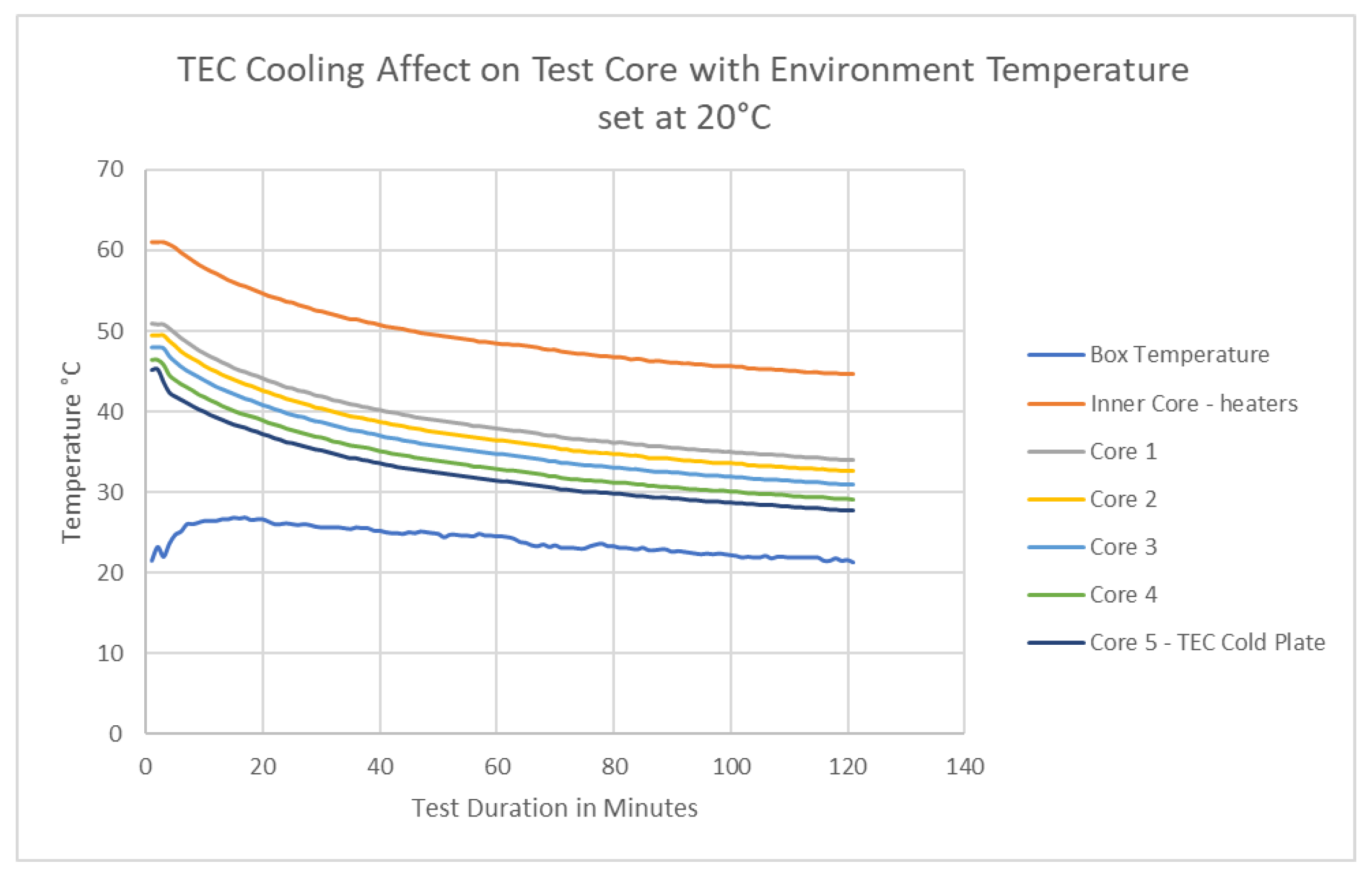
These tests measured the temperature reduction and the time to stabilization with a fixed TEC current in an environment set at 20 °C. The heating resistors at the inner core position were set with a 20 W load, simulating the losses generated in the winding. The box temperature was set to 20 °C, and the core test sample was allowed to stabilize. This resulted in an inner core temperature of 61 °C. The TEC current was then set to 1 A (1 A, 11.03 V, and 11.04 W), and the temperatures were allowed to stabilize, as seen below in
Figure 8. The final internal inner core position temperature was 44.6 °C. This resulted in a 16.4 °C drop in temperature at the inner core position.
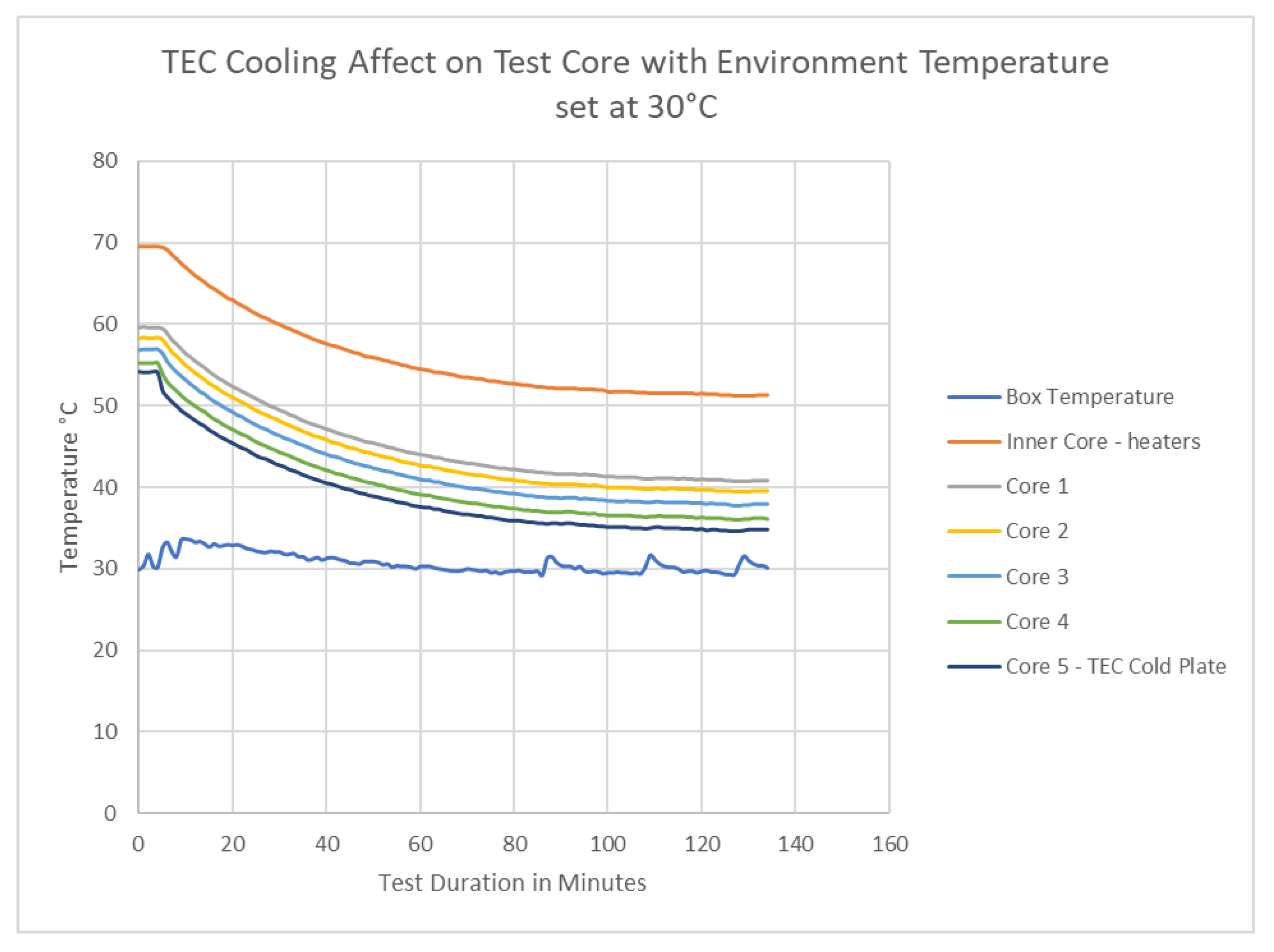
3.3. Cooling Testing: 30 °C Environment Test
These tests measured the temperature reduction and the time to stabilization with a fixed TEC current in an environment set at 30 °C. The heating resistors at the inner core position were set with a 20 W load, simulating the losses generated in the winding. The box temperature was set to 30 °C, and the core test sample was allowed to stabilize. This resulted in an inner core temperature of 69.6 °C. The TEC current was then set to 1 A (1 A, 11.03 V, and 11.04 W), and the temperatures were allowed to stabilize, as seen below in
Figure 9. The final internal inner core position temperature was 51.3 °C. This resulted in a 17.7 °C drop in temperature at the inner core position.
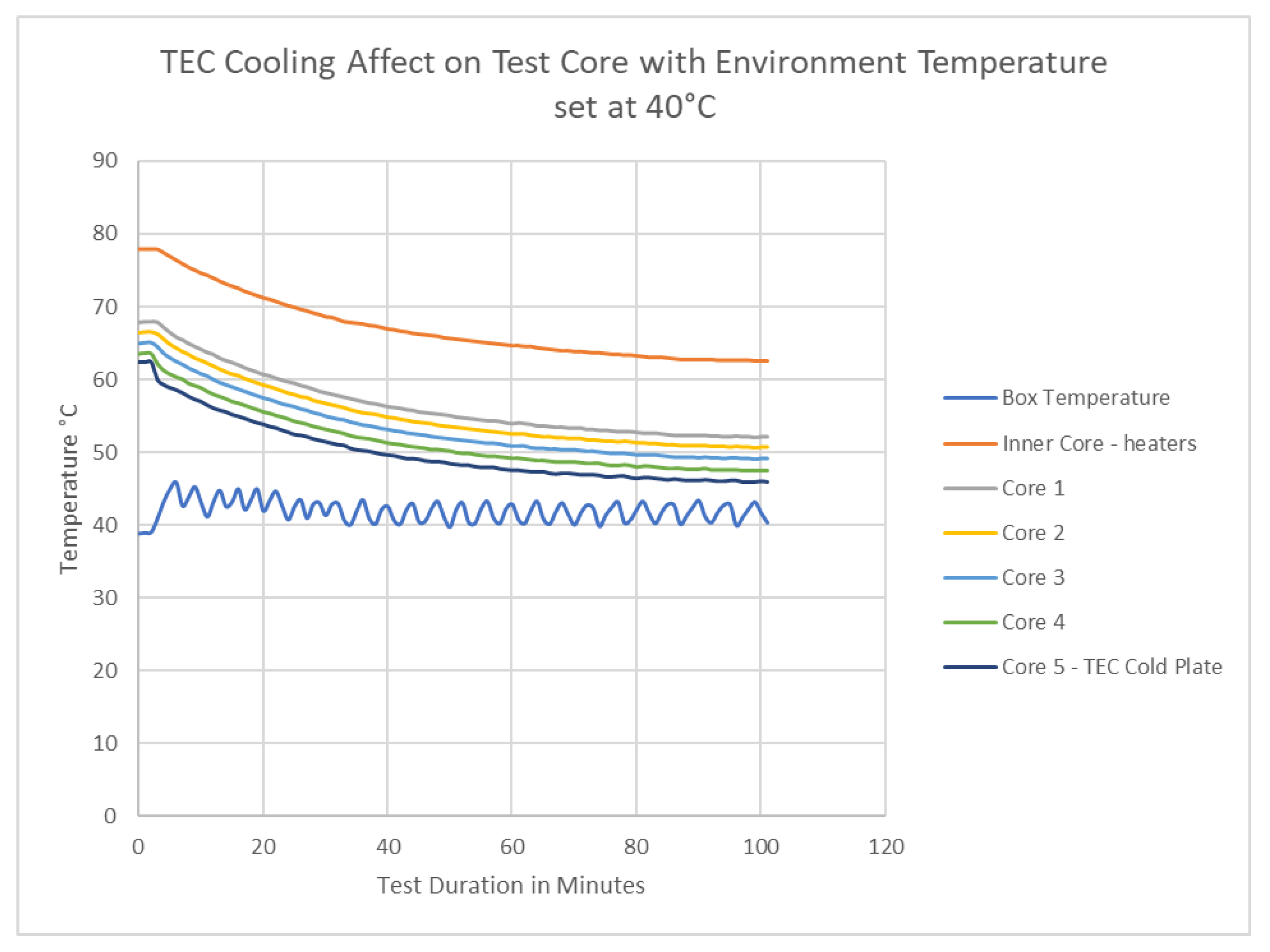
3.4. Cooling Testing: 40 °C Environment Test
These tests were conducted to measure the temperature reduction and the time to stabilization with a fixed TEC current in an environment set at 40 °C. The heating resistors at the inner core position were set with a 20 W load, simulating the losses generated in the winding. The box temperature was set to 40 °C, and the core test sample was allowed to stabilize. This resulted in an inner core temperature of 77.9 °C. The TEC current was then set to 1 A (1 A, 11.03 V, and 11.04 W), and the temperatures were allowed to stabilize, as seen below in
Figure 10. The final internal inner core position temperature was 62.5 °C. This resulted in a 15.4 °C drop in temperature at the inner core position.
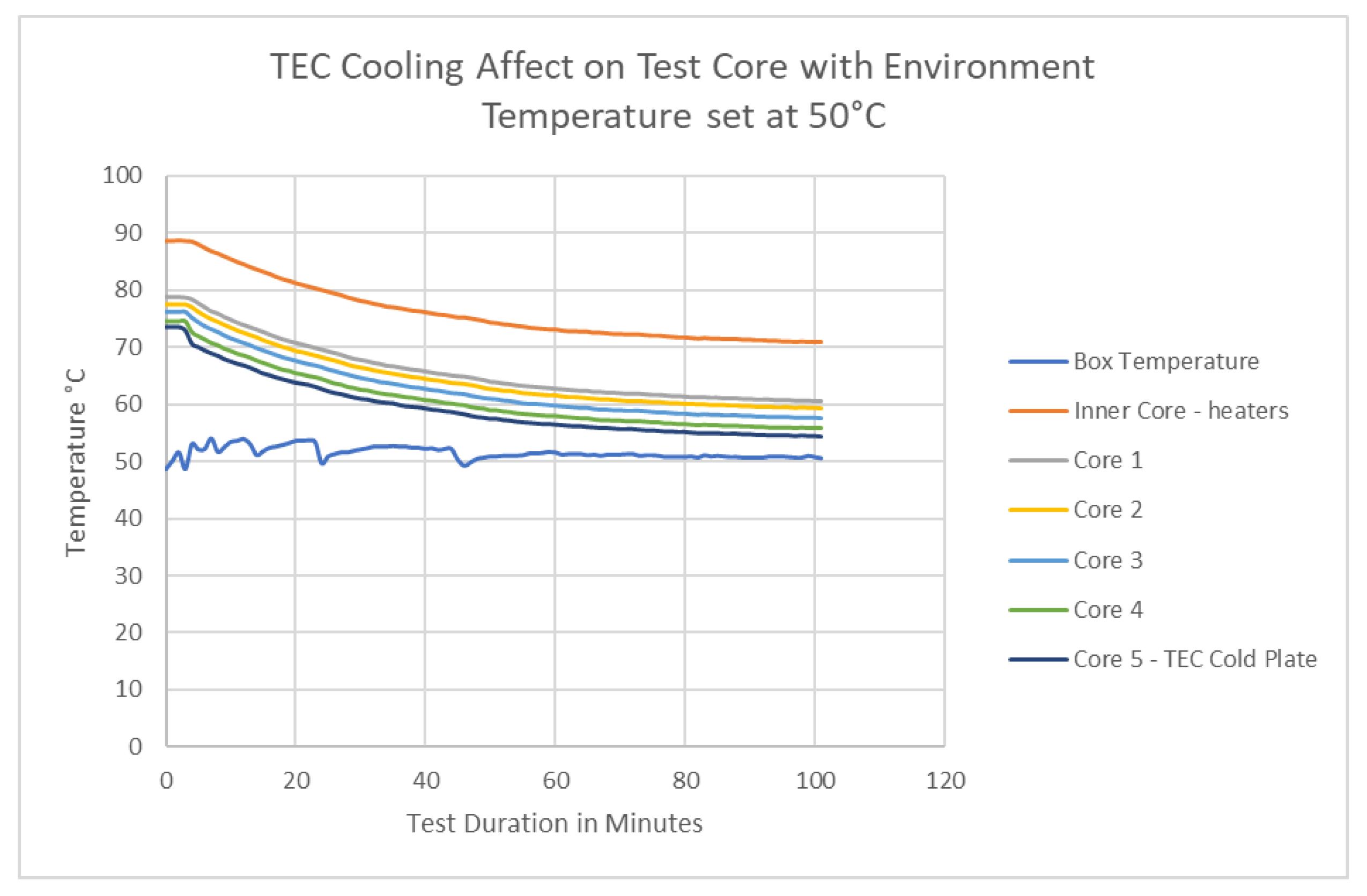
3.5. Cooling Testing: 50 °C Environment Test
These tests were conducted to measure the temperature reduction and the time to stabilization with a fixed TEC current in an environment set at 50 °C. The heating resistors at the inner core position were set with a 20 W load, simulating the losses generated in the winding. The box temperature was set to 50 °C, and the core test sample was allowed to stabilize. This resulted in an inner core temperature of 88.6 °C. The TEC current was then set to 1 A (1 A, 11.03 V, and 11.04 W), and the temperatures were allowed to stabilize, as shown below (
Figure 11). The final internal inner core position temperature was 70.9 °C. This resulted in a 17.7 °C drop in temperature at the inner core position.
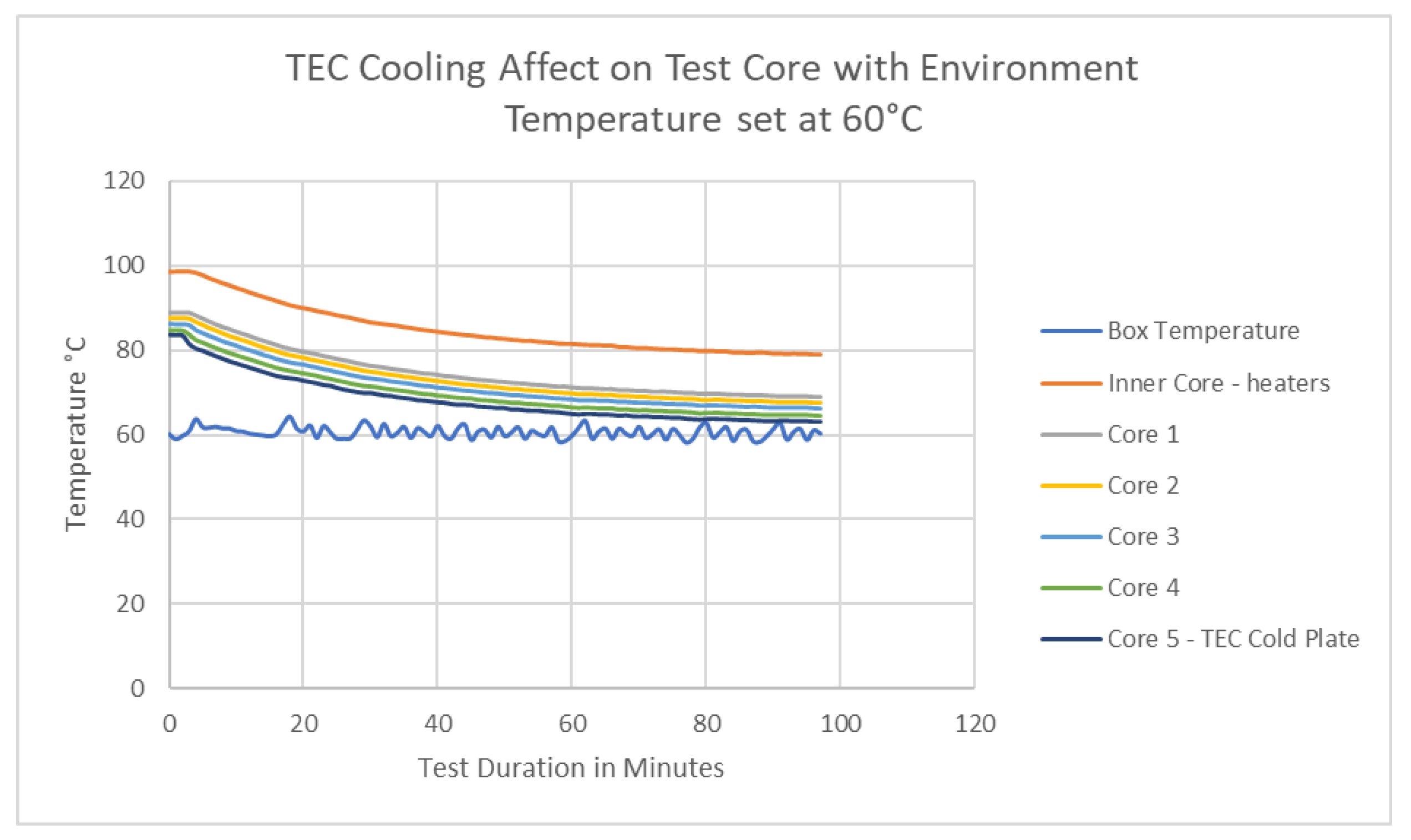
3.6. Cooling Testing: 60 °C Environment Test
These tests were conducted to measure the temperature reduction and the time to stabilization with a fixed TEC current in an environment set at 60 °C. The heating resistors at the inner core position were set with a 20 W load, simulating the losses generated in the winding. The box temperature was set to 60 °C, and the core test sample was allowed to stabilize. This resulted in an inner core temperature of 98.5 °C. The TEC current was then set to 1 A (1 A, 11.03 V, and 11.04 W), and the temperatures were allowed to stabilize, as seen below (
Figure 12). The final internal inner core position temperature was 78.9 °C. This resulted in a 19.6 °C drop in temperature at the inner core position.
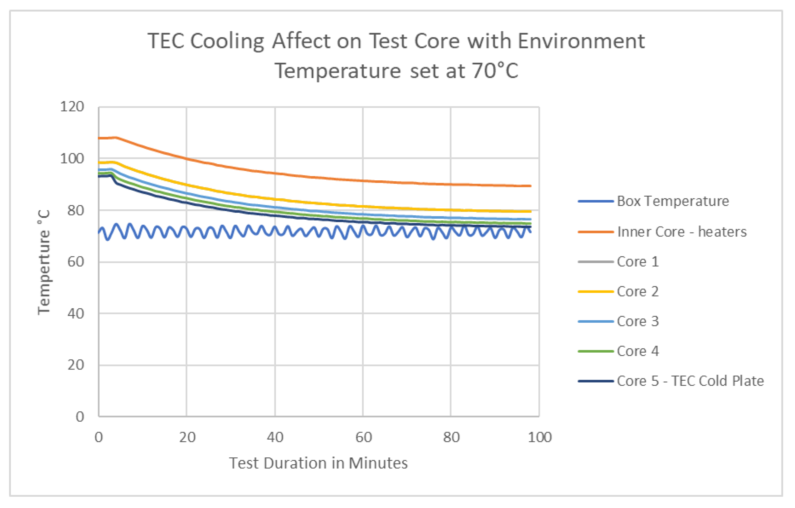
3.7. Cooling Testing: 70 °C Environment Test
These tests were conducted to measure the temperature reduction and the time to stabilization with a fixed TEC current in an environment set at 70 °C. The heating resistors at the inner core position were set with a 20 W load, simulating the losses generated in the winding. The box temperature was set to 70 °C, and the core test sample was allowed to stabilize. This resulted in an inner core temperature of 107.9 °C. The TEC current was then set at 1 A (1 A, 11.03 V, and 11.04 W), and the temperatures were allowed to stabilize, as seen below (
Figure 13). The final internal inner core position temperature was 89.4 °C. This resulted in an 18.5 °C drop in temperature at the inner core position.
4. Analysis
4.1. TEC Heating
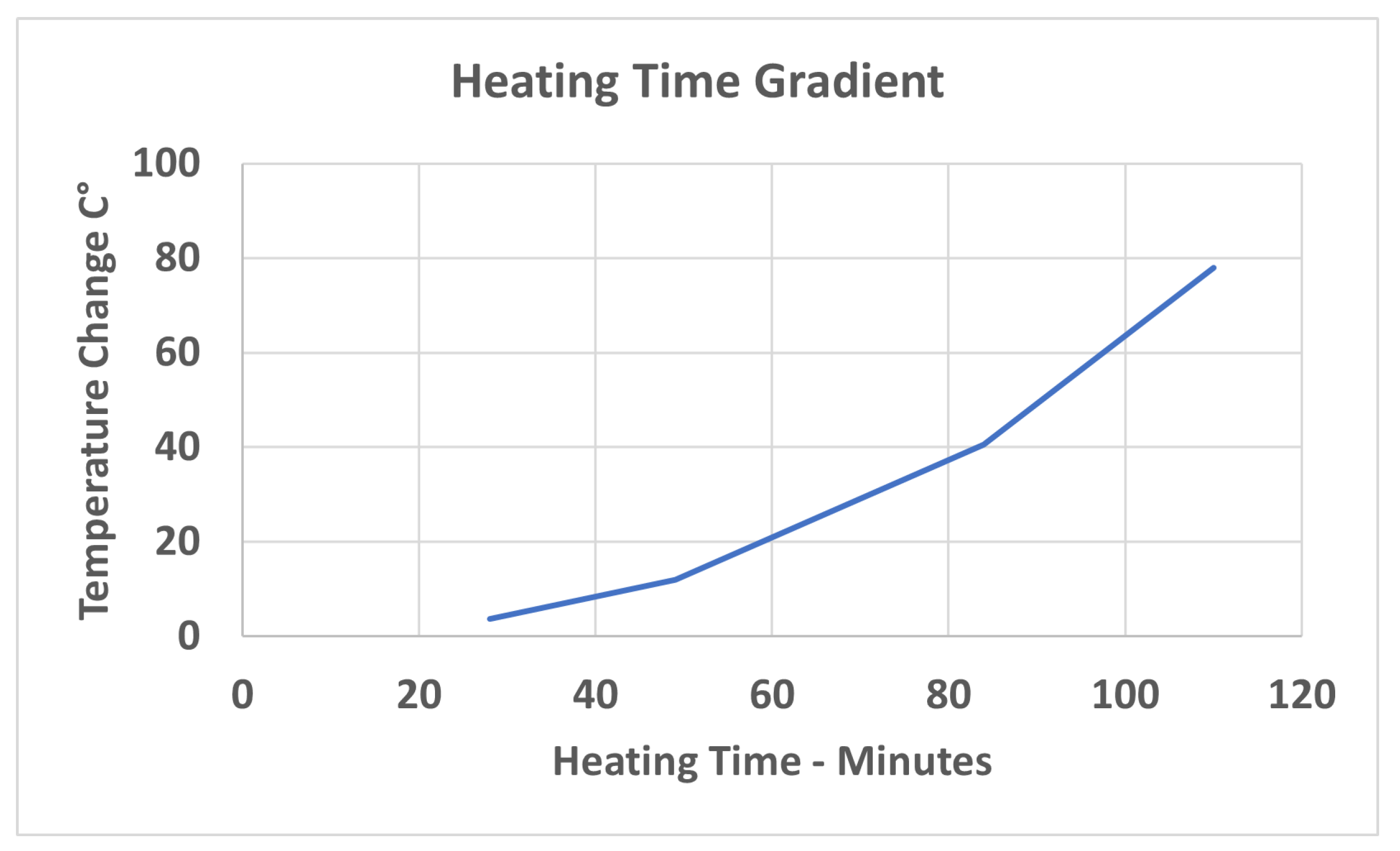
The test results show that in a 0 °C environment, when unpowered (equivalent to a motor that has been de-energised), TECs can effectively pump heat into a core, raising the core and windings to temperatures greater than 78 °C, thus enabling temperatures to be kept well above dew point conditions.
The heating time gradient was plotted from data in
Table 3 and can be seen in
Figure 14. Because of the mass of the core and windings, there is a thermal lag in the heating process.
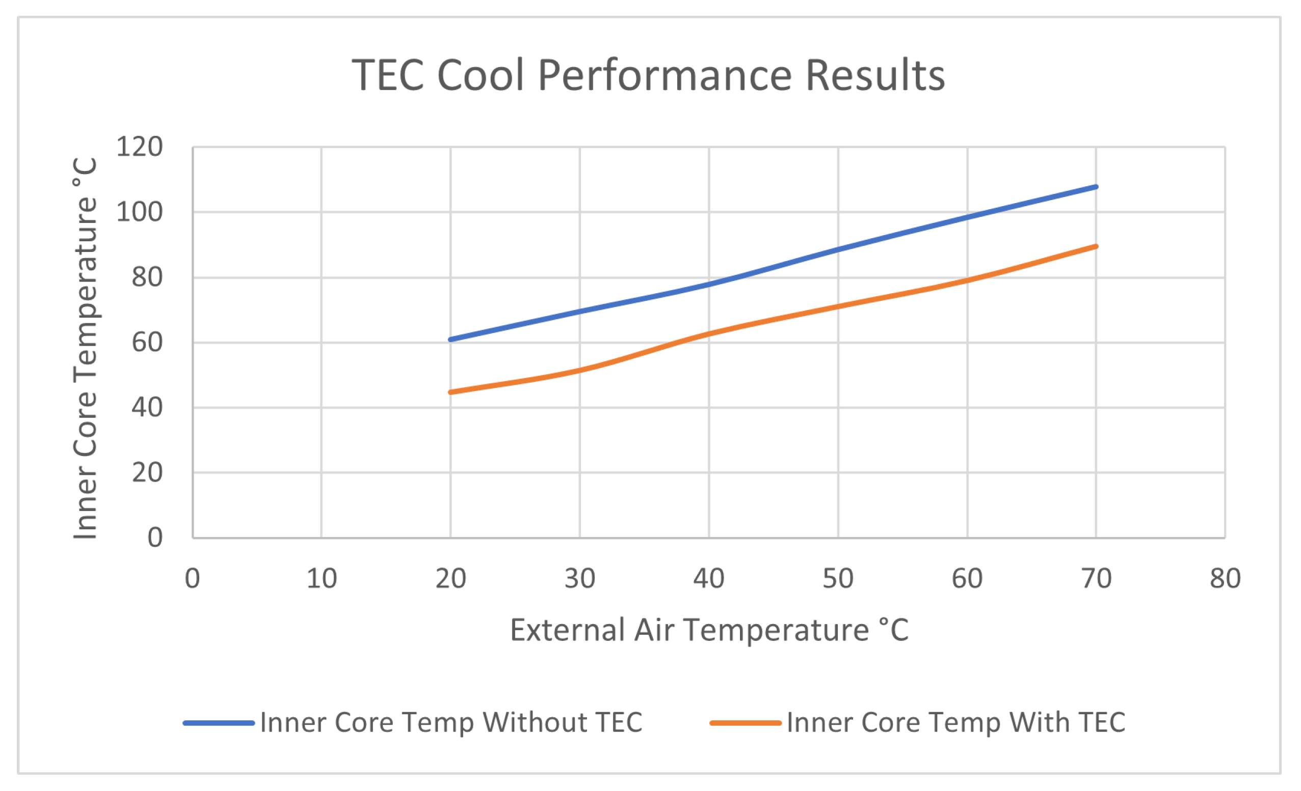
4.2. TEC Cooling
The results show that increasing the environment temperature increases the motor winding temperature, which is expected. The TEC cooling effect is linear and independent of external temperatures across a wide range of temperatures, as shown in
Figure 15. Our tests have shown that the TEC will work up to 70 °C.
Motors are designed with a maximum environmental temperature of 40 °C, but in many countries, maximum temperatures can exceed this temperature. In Melbourne, Australia, this temperature is exceeded only a few days a year in the summer, but in Mt. Isa, Australia, temperatures can exceed 45 °C for multiple days in the summer. Motors installed in package installations, such as air compressor stations and large freezer works, can be enclosed, and high environmental temperatures, sometimes combined with solar radiation, can have a large impact on motor temperatures. In these conditions, maximum insulation temperatures are often exceeded, impacting motor working life and whole-of-life costs. In some cases where motors initiate alarms when specified temperatures are exceeded, operations reduce loads or take the plant out of service, affecting production targets.
TECs assembled into a simple heat extraction system could provide the ability to assist cooling when extreme environmental temperatures are being experienced. By lowering motor winding temperatures, electrical insulation systems can be kept below insulation class limits when external temperatures exceed 40 °C. With TEC-assisted cooling, it is possible to maintain production and reduce the over-temperature effect to insulation systems. This system is simple to construct as an add-on and does not impact the original cooling design.
4.3. TEC Temperature Control
In principle, the ability of the TEC to add heat and extract heat enables the TEC to control motor temperatures over a wide range of conditions caused by load variations and varying climatic conditions.
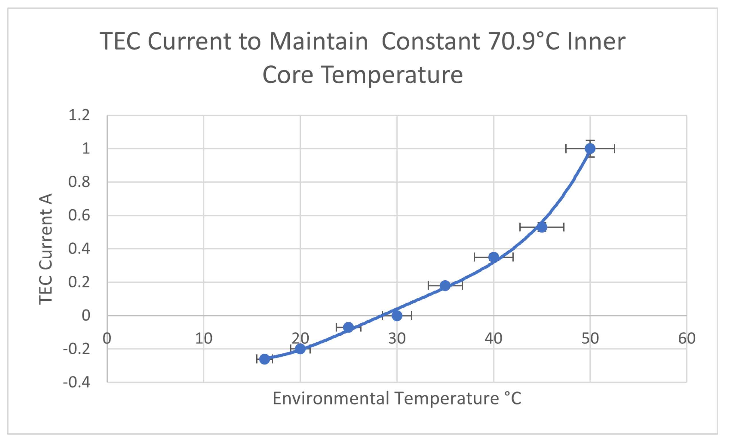
In this experiment, the internal losses were set at 20 W by resistive heating, and the TEC current was adjusted to keep the inner core temperature stable at 70.9 °C. The inner core temperature was measured, initially, with an environmental temperature of 30 °C, a typical mid-range temperature for motors. By maintaining a constant temperature, winding temperature stresses in the winding insulation system are greatly reduced.
The test equipment and test sample were set up, with the external temperature set at 5 °C intervals and the TEC current adjusted to maintain 70.9 °C at the winding location. Once temperatures were stable, the TEC current was recorded and can be seen plotted in
Figure 16 with 5% error bars.
The TEC could easily maintain the 70.9 °C inner core temperatures over a considerable range of temperatures of the environment. This temperature control achieves two goals. Firstly, it keeps internal temperatures well above dew point values, eliminating condensation issues. Secondly with the winding being held at a constant temperature, the magnitude of thermal cycling, T, is greatly reduced or eliminated.
The testing has shown that if TEC thermal control units are installed with a motor, the thermal control will significantly reduce normal thermal stresses and moisture ingress, leading to a more reliable motor.
5. Discussion
The arrangement of the TEC enables the direction of the heat flow to be reversed by simply changing the supply polarity to the TEC. This enabled heat to be pumped into or out of our core test sample.
Because of the mass of our core sample, there is a temperature equalization lag as external temperatures vary from cold to hot. Lag in temperature equalization becomes longer with heavier, full-sized electrical machinery.
Depending on humidity and internal and external temperature differences, the dew point can easily be achieved, causing condensation inside a motor, wetting surfaces and causing the uptake of moisture by the electrical winding insulation, leading to insulation failure. Pumping heat into a motor raises internal temperatures, keeping the motor internals above the dew point, stopping internal condensation, and reducing moisture absorption by the electrical insulation.
Additionally, keeping motors hot reduces the temperature difference between a full load and low loads, which reduces the T thermal cycling stresses and reduces mechanical stresses on the insulation, wedging, and bracing systems.
From our earlier work [
6,
15,
16] on our core sample and test motor, the effects of variations in pumping heat were relatively linear between the core sample and the test motor. The application of the TECs to the test segment was able to reduce winding location temperatures by 25 °C with just 8 W into the TECs. These results are consistent with the results on the test motor with only 57% coverage by TECs, in which we could reduce slot location temperatures by 8.1 °C with 35 W input to the TECs. The relative area above the core covered by the TECs is important, as areas not covered by the TECs add this extra load to the TECs. This is due to the uncovered areas not being able to remove as much heat per unit area. As our test core is approximately 1/10 the volume of our test motor, if we assemble 10 core sections, equating to our test motor without the losses from uncovered surfaces and extrapolating, this would provide on the order of a 25 °C reduction in temperature for 80 W input to the TECs. This equates to a power budget to run the TECs on the order of 15% of the power output of the motor to lower the slot winding location temperature by 25 °C for this motor. We believe that this power budget will linearly transpose to differently sized motors of similar construction.
Our system is not intended to replace existing systems but to increase the efficiency of the standard cooling systems. TECs have only a small volume, and their addition to a cooling arrangement is minimal. However, what is novel is that they can pump heat in both directions by simply reversing the TEC supply’s polarity, thus enabling internal temperatures to be maintained, reducing thermal stresses, and eliminating condensation issues.
This work has demonstrated that TECs can add heat or remove heat from a test section of an electric motor or generator in varying ambient conditions. This supports the conjecture that TECs are capable of maintaining a motor core at a selected temperature in varying or even extreme ambient conditions. In application to motors and generators, one would need to take into consideration motor size, its operating characteristics, and the external ambient conditions to design a system to maintain a desired core temperature. This approach could also be used to reduce thermal stress for a desired thermal operating range that is wider than a single set point.
This study supports the hypothesis that the application of TECs allows the constant control of a high temperature that reduces damage from varying thermal stresses and eliminates internal condensation by maintaining safe internal temperatures.
6. Conclusions
Traditional methods of extracting heat caused by internal losses involve systems such as ribs to increase surface area and fans to extract heat from surfaces. In this paper, TECs were utilized to pump heat in and out of a core sample setup to represent a motor core and winding. This work has shown that embedded TECs can be used for active thermal control, stabilizing winding location temperatures in an environment with varying ambient temperatures. Active thermal control is beneficial because it can keep a constant temperature on the inner core winding area, eliminating thermal stresses on the electrical insulation, thus greatly increasing winding life. These results also indicate the possibility to maintain the temperature of the windings above the dew point so as to prevent internal condensation and electrical winding insulation from absorbing moisture.
We have extrapolated a power budget to run the TECs on the order of 15% of the power output of a 550 W motor (our original test motor) to lower the slot-winding location temperature by 25 °C. Even if these figures may seem high, they can ensure that mission-critical use is possible even in extreme conditions (such as a heat wave that would trip normal protections in electrical machines).
Our future work will consider means of precision control of motor core temperatures using TECs and will use an environmental chamber with a TEC-equipped motor core to explore the control of phenomena at the dew point.
Author Contributions
Conceptualization, S.L., R.M. and J.C.; investigation, S.L.; project administration, R.M., resources, M.L. and J.C.; supervision, R.M. and M.L.; writing—original draft preparation, S.L. and R.M. writing—review and editing, T.O., J.C., M.L. and R.M. All authors have read and agreed to the published version of the manuscript.
Funding
This research received no external funding.
Data Availability Statement
The data presented in this study are available on request from the corresponding author.
Conflicts of Interest
The authors declare no conflict of interest.
References
- McCoy, G.A.; Douglass, J. Premium Efficiency Motor Selection and Application Guide—A Handbook for Industry; US Department of Energy: Washington, DC, USA, 2016; p. 136. [Google Scholar]
- Nikbakhsh, A.; Izadfar, H.R.; Jazaeri, M. Classification and Comparison of Rotor Temperature Estimation Methods of Squirrel Cage Induction Motors. Measurement 2019, 145, 779–802. [Google Scholar] [CrossRef]
- Fedorova, K.; Podzorova, V.; Gulyaev, I.; Anuchin, A. Rotor Thermal Model for Real-Time Protection in Adjustable Induction Motor Drives. In Proceedings of the 2018 53rd International Universities Power Engineering Conference (UPEC), Glasgow, UK, 4–7 September 2018. [Google Scholar]
- NEMA. Nema MG 1-2016 Motors and Generators. 2016. Available online: https://www.nema.org/docs/default-source/standards-document-library/ansi_nema-mg-1-2016-contents-and-foreword.pdf?sfvrsn=f27547b8_1 (accessed on 20 September 2019).
- Kang, M.; Wang, H.; Guo, L.; Shi, T.; Xia, C. Self-Circulation Cooling Structure Design of Permanent Magnet Machines for Electric Vehicle. Appl. Therm. Eng. 2020, 165, 114593. [Google Scholar] [CrossRef]
- Lucas, S.; Marian, R.; Lucas, M.; Ogunwa, T.; Chahl, J. Employing the Peltier Effect to Control Motor Operating Temperatures. Energies 2023, 16, 2498. [Google Scholar] [CrossRef]
- NEMA. NEMA Standards Publication MG 1-2009 Motors and Generators. 2009. Available online: https://law.resource.org/pub/us/cfr/ibr/005/nema.mg-1.2009.pdf (accessed on 20 September 2019).
- Society, I.P. Energy. In IEEE Guide for Insulation Maintenance of Electric Machines. IEEE Std 56™-2016; IEEE: Piscataway, NJ, USA, 2016. [Google Scholar]
- EASA. EASA Technical Manual. 2002. Available online: https://phys.org/news/2014-11-secret-dragonflies-flight.html (accessed on 20 September 2019).
- Walker, J.H. Large Synchronous Machines: Design, Manufacture, and Operation; Oxford University Press: Oxford, UK, 1981; Volume 14. [Google Scholar]
- Menz, B.Y.B. Cooling High-Horsepower Motors with Heat Exchangers. Plant Eng. 2001, 55, 36–38. [Google Scholar]
- Portal, E.E.E. Cooling and Ventilation of Electric Motors (IC). 2011. Available online: http://test.electrical-engineering-portal.com/cooling-and-ventilation-of-electric-motors-ic (accessed on 20 September 2019).
- Bertram, B. How to be Cool-Life Lessons for Electric Motors. Engineeringlive 2014. Available online: https://www.engineerlive.com/content/how-be-cool-life-lessons-electric-motors (accessed on 23 September 2019).
- Lucas, S.; Marian, R.; Lucas, M.; Ogunwa, T.; Chahl, J. Research in life extension of electrical motors by controlling the impact of the environment through employing Peltier effect. Energies 2022, 15, 7659. [Google Scholar] [CrossRef]
- Lucas, S.; Bari, S. Increased Life Span by Cooling the Laminated Core Segment of Motors to Reduce Material and Energy Costs Over the Lifecycle of Motors. Therm. Sci. Eng. Prog. 2021, 13, 061022. [Google Scholar]
- Lucas, S.; Bari, S.; Marian, R.; Lucas, M.; Chahl, J. Cooling by Peltier effect and active control systems to thermally manage operating temperatures of electrical Machines (Motors and Generators). Therm. Sci. Eng. Prog. 2022, 27, 100990. [Google Scholar] [CrossRef]
| Disclaimer/Publisher’s Note: The statements, opinions and data contained in all publications are solely those of the individual author(s) and contributor(s) and not of MDPI and/or the editor(s). MDPI and/or the editor(s) disclaim responsibility for any injury to people or property resulting from any ideas, methods, instructions or products referred to in the content. |
© 2023 by the authors. Licensee MDPI, Basel, Switzerland. This article is an open access article distributed under the terms and conditions of the Creative Commons Attribution (CC BY) license (https://creativecommons.org/licenses/by/4.0/).


