1. Introduction
Centrifugal pumps are definitely of interest in a wide range of applications in medicine [
1], chemistry and biology [
2,
3], as well as micro-fluidics and nano-fluidics [
4,
5,
6]. For efficient and stable operation, the low vibration and noise characteristics, as well as the ultra-low pressure pulsation characteristics of centrifugal pumps, are also gaining attention [
7,
8]. However, the strong rotor–stator interaction (RSI) in the centrifugal pump is the primary source of high-energy pressure pulsation, which can cause damage to the impeller and other hydraulic components [
9]. To improve the stability and safety of the system, it is crucial to suppress the pressure pulsation characteristics in centrifugal pumps.
In recent years, the study of pulsation in centrifugal pumps and fans has been a fairly common research direction. The method of numerical simulation is widely used in research. Ding et al. [
10] analyzed the effect of the blade trailing edge filing on the performance and unsteady pressure pulsations of a low-specific-speed centrifugal pump using the
SST k-ω turbulence model. In the research of Jiang et al. [
11] and Zhao et al. [
12], the results obtained by the
SST k-ω model deviated somewhat from the experiment. In recent years, more advanced DES (detached eddy simulation) and LES (large eddy simulation) methods have been widely used with an improvement in computer performance. Gangipamula et al. [
13] studied the fluid dynamic characteristics of a narrow channel centrifugal pump via DES. Based on the same turbulence model, Wang et al. [
14] successfully captured the axial vortex in a centrifugal pump as a turbine with an S-Blade impeller. From the research by Cai et al. [
15], the DES method could accurately predict pressure pulsations in centrifugal fans and their downstream pipe, which agreed well with the experimental results. Considering that the DES method is more resource-intensive, Posa and Zhang et al. [
16,
17] predicted the complex flow structure in the pump based on the LES calculation method. The study found that pressure pulsation amplitude increased under the small flow rates, the discrete characteristic frequency components were rich in the low-frequency band and the amplitude of
fbpf increased significantly. The pressure fluctuation energy induced by the RSI is dominant in unsteady hydraulic excitation.
Based on RSI theory, Gülich and Rodriguez [
18,
19] deduced the formula of the excitation frequency generated by the RSI of the impeller–diffuser under the given combination of the different blade numbers. Meanwhile, the formula for judging the mode shape of the impeller under the RSI was given for the designer’s reference to select the appropriate number of blades. Spence [
20] studied the effects of four geometric parameters on the pressure pulsation of centrifugal pumps. Increasing the gap between the impeller and the volute was found to effectively and reasonably reduce the amplitude of pressure pulsation [
21]. However, a larger gap would reduce head and efficiency [
22].
In the study of unique impeller structures, adding splitter blades could effectively improve performance and suppress the pressure pulsation in the pump [
23,
24]. Zhang and Gu et al. [
25,
26,
27] studied the effect of splitter blades on the flow characteristics in the pump via experiments and numerical simulation and found that splitter blades can effectively optimize the jet wake structure, improve the internal flow structure of the impeller channel and reduce the pressure fluctuation in the pump. In double-suction centrifugal pumps, a back-to-back impeller structure with staggered blades is widely used to reduce the radial force distribution and pump vibration [
28,
29]. Zeng and Fu et al. [
30,
31] found that the staggered impeller had little effect on the performance of a double-suction pump, and the pressure pulsation level in the volute was significantly reduced when the blade was evenly staggered.
In the present paper, referring to the design idea of the double-suction pump, a staggered impeller structure is proposed in the single-suction low-specific-speed centrifugal pump. The dynamic pressure pulsation characteristics are investigated using the LES method. Emphasis is laid on the pressure pulsation energy caused by different impeller structures under various operating conditions. In addition, the time–frequency domain of pressure pulsation at each measurement point near the tongue was analyzed. The suppression mechanism of the low-frequency signal induced by dynamic and static interference via the staggered impeller was elucidated. The research results can provide a reference for optimizing low-vibration-noise pump impellers.
2. Case Study and Numerical Investigation
2.1. Model Pump Scheme
To reduce the influence of complex parameters on the pressure pulsation characteristics in the model pump and reduce the difficulty of design and processing, a single-stage, single-suction centrifugal pump with low specific speed (
ns = 69) was the object of the current study. The main parameters are shown in
Table 1.
The original blades were divided into the front and the posterior layer blade, which were connected by a diaphragm. The original and staggered impellers are shown in
Figure 1. The thickness of the diaphragm was 3 mm. The original scheme is defined as Or. After the blades were staggered by 10°, 20° and 30°, three staggered impeller schemes, St10, St20, and St30, were formed. The different staggered impeller schemes are shown in
Figure 2. The total width of the front and posterior impeller outlet was still 17 mm.
2.2. Mesh Generation
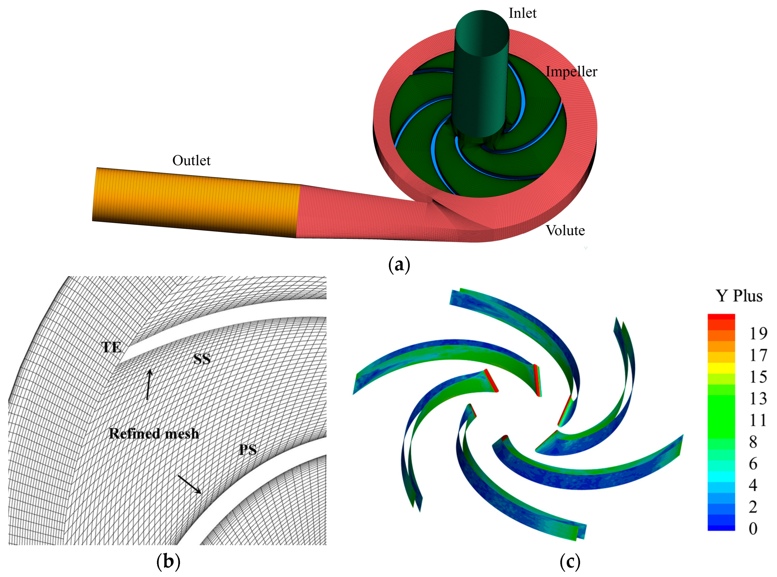
The calculation domain of the model pump includes four parts: the inlet section, the impeller, the volute and the outlet section. To improve the calculation accuracy, the inlet and outlet sections are properly extended to ensure that they do not affect the flow structure within the impeller and volute. The structured grid can be easily fitted to the boundary in a fast and high-quality manner. The hexahedral structured grid can well control the orthogonal boundary layer and streamline distribution. It exhibits good truncation error and convergence throughout the numerical calculation process. Moreover, it is suitable for calculating fluid and surface stress concentration in the centrifugal pumps. Therefore, ANSYS-ICEM was used in this paper to generate the structured mesh grids of the computational domain, as shown in
Figure 3a. Furthermore, the boundary layer encryption was applied to the areas where the pressure gradient in the pump was high, and it was easy for flow separation to occur, especially on the blade wall. The wall encryption of the impeller flow channel is shown in
Figure 3b. A small Y plus value was required to obtain a better flow structure of the model pump, especially for the impeller.
Figure 3c gives the Y plus value on the blade surface for the current study. During the simulation, the Y plus insensitive treatment was used by the
SST k-ω turbulent model to treat the flow field near the solid wall, which could automatically dispose the mesh near the wall. It is noted that the average Y plus value for the impeller was about 5 and was lower on the pressure surface. We believed that using refined mesh could meet the calculation requirements of LES and obtain accurate numerical simulation results.
Seven different grid number schemes were designed to check the mesh’s sensitivity. The performance of different grid number schemes was predicted under the rated flow rate, and the change in hydraulic efficiency was monitored, as seen in
Figure 4. The efficiency of the model pump gradually decreased as the number of grids increased. When the number of grids exceeded 7.94 × 10
6, the efficiency tended to be flat. When the accuracy and computational resource usage were considered, the total grid number was 7.94 × 10
6, and the impeller grid number was 4.0 × 10
6.
2.3. Solution Parameters
In this study, the SIMPLEC algorithm was used to couple pressure and velocity. The steady-state results calculated using the
SST k-ω model were used as the initial conditions for unsteady-state calculations. The
SST k-ω model combines the advantages of the traditional
k-ε and
k-ω models, which can better deal with the flow separation near the wall. Considering that the large eddy simulation (LES) model has sufficient ability to deal with complex flows, it was applied for the prediction of unsteady pressure pulsation characteristics [
32,
33]. For incompressible fluids, a filter and a continuity equation were added to the N-S equation to obtain the momentum equation, which is defined in Equation (1):
The Smagorinsky–Lilly subgrid scale (SGS) fixed-coefficient model [
7] was applied to close the equations, which is defined in Equation (2).
where
is the strain rate tensor and
is the SGS stress viscosity.
where Δ is the filter scale and
CS = 0.1 is a dimensionless parameter called the Smagorinsky coefficient.
The inlet boundary condition is a uniform velocity inlet, which is given according to the operating conditions and the inlet suction diameter. The specific turbulence characteristics are given, where the turbulence intensity is 5%. The outlet boundary condition is the pressure outlet. In numerical calculations, all physical walls are non-slip walls. Second-order implicit time discretization was used, and the calculated residual was set to 1 × 10⁻⁶.
2.4. Monitoring Points
To explore the influence of the staggered impeller on the pressure pulsation characteristics in the pump, 20 uniformly distributed pressure pulsation monitoring points were set up in the volute, near the front cover of the impeller, as shown in
Figure 5. The pressure fluctuation signals from the last 15 rotation cycles of the numerical calculation results were processed and analyzed. The Hanning window function [
34] reduces the energy leakage caused by signal truncation. It is a bell-shaped curve that is symmetric around the middle of the interval. The Hanning window touches zero at both ends, removing any discontinuity, while the traditional window functions, such as the rectangular window, stop just shy of zero, meaning that the signal will still have a slight discontinuity. It is defined as follows:
2.5. Experimental Platform
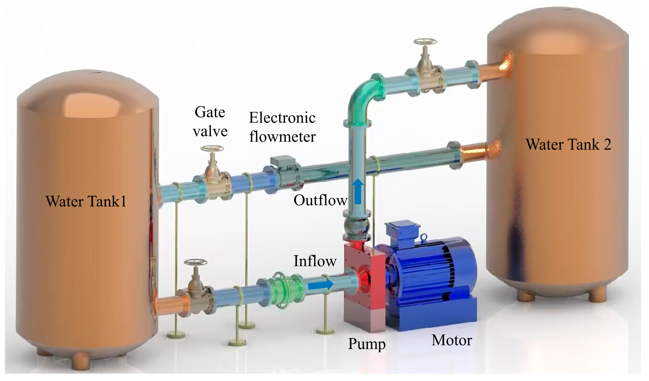
The original impeller model pump was tested on the closed test platform to verify the reliability of the numerical method [
35], as shown in
Figure 6. The high-precision pressure test equipment was used to measure the pressure information in the model pump. The SCM05 model of Belgium LMS company was used for data acquisition, and the pressure sensor was the PCB113B27X model of the American PCB company. The water temperature was maintained at about 25° throughout the test. The inverter was used to ensure that the speed of the model pump at different flow rates was about
n = 1450 rpm. The arrangement of the pressure fluctuation test points is shown in
Figure 7.
3. Results
3.1. Validation of the Numerical Method
The accuracy of the numerical method was verified based on the experimental results of the original impeller model pump. The comparison results of the head coefficients of different calculation methods are shown in
Figure 8. The head coefficient curve predicted by the LES method is more consistent with the experimental value under large flow conditions. Under rated conditions, the prediction error is only about 0.5%. The predicted head of the RANS method is slightly lower than the experimental value, and the error is 3% under the design condition.
In order to verify the reliability of the LES calculation method,
Figure 9 compares the LES calculation and the experimental results of the 20 pressure pulsation monitoring points in the circumferential direction of the volute under the design conditions. It can be found that the predicted dominant frequency amplitude of each monitoring point is in good agreement with the experimental results, and there is almost no error at the measuring points, such as P1 and P5. In order to further verify its reliability,
Table 2 extracts the average error of amplitude at the blade frequency (
fbpf) and 2 times blade frequency (2
fbpf) of 20 measuring points in the experiment and simulation. It can be found that the average error of amplitude at
fbpf predicted by the LES numerical calculation method is 13.85%, while that of amplitude at 2
fbpf is only 2.24%. Therefore, the LES method can accurately predict the pressure fluctuation characteristics of the low-specific-speed centrifugal pump.
3.2. Unsteady Pressure Pulsations
For the convenience of analysis, the pressure signal was non-dimensionalized and the pressure fluctuation coefficient was defined as follows:
In the equation, P is the pressure of the monitoring point; Pav is the average pressure of the monitoring points; ρ is the water density and u2 is a constant value of 19.74 m/s.
3.2.1. Overall Pressure Pulsation Energy Analysis
The numerical calculation of pressure pulsation in different staggered impeller models was carried out to explore the influence of different staggered impeller structures on the pressure pulsation energy in the pump.
Q/Qd = 0.8, 1.0 and 1.2 were selected for comparative analysis. The root mean square error (
RMSE) was used to characterize the pressure pulsation energy in the pump, as shown in Equation (7). The amplitude information of 20 pressure pulsation monitoring points in the 10–1000 Hz frequency band was processed using
RMSE.
In the equation, CPi is the pressure coefficient value of the measuring point, is the average value of the pressure coefficient and N is the number of samples of the measured pressure coefficient.
Figure 10 shows the pressure fluctuation energy distribution of different impeller schemes under different working conditions. It can be found that the highest point of the pressure pulsation energy of the four impeller schemes under different working conditions appears near the P3 point downstream of the tongue. As a result, the vicinity of the tongue is the site of the most rotor–stator interaction (RSI) in the pump, causing high-intensity pressure pulsation to peak downstream in the tongue.
Additionally, it was discovered that the staggered arrangement of blades significantly reduces the pressure pulsation energy in the pump within the 10–1000 Hz range, and the suppression impact increases with the staggered angle. The optimum effect results from evenly spaced blades. Compared with the design condition, under the condition of 0.8Qd, the peak value of the pressure fluctuation energy of the Or scheme is transferred to the P2 point, indicating that the RSI between the impeller and the tongue is weak under the low flow condition, and the pressure fluctuation energy decreases with increasing distance from the tongue. Under the condition of flow 1.2Qd, the pressure pulsation energy level increases when the blade is staggered by 10°, and this is gradually suppressed as the staggered angle increases.
From the overall comparison, it can be found that the staggered arrangement of the blades has the most significant suppression effect on the pressure pulsation energy at points P1–P3 near the tongue.
The suppression effect of the staggered impeller structure on the pressure pulsation energy in the pump was quantified by calculating the
RMSE mean change, and the calculation method is shown in Equation (8).
Table 3 shows the reduction in the
RMSE mean value of different impeller schemes under three working conditions. From the table, it can be seen that under different working conditions, the St30 scheme, that is, the uniform staggered blade, has the best suppression effect on the pressure pulsation energy in the pump, and the suppression amplitude is above 50%.
3.2.2. Pressure Pulsation Energy Analysis near the Tongue
The pressure pulsation energy in the pump is mainly determined by the energy of the main frequency amplitude, and the pressure pulsation energy near the tongue is dominant. The above analysis shows that the staggered impeller has the most apparent effect on the pressure pulsation energy near the tongue. In order to study the suppression mechanism of the staggered impeller structure on pressure pulsation energy, the pressure pulsation characteristics of three monitoring points P1, P2, and P3 of the St30 scheme under design conditions were studied in depth, and pressure pulsation monitoring points were set at the center outlet of the front and the posterior impeller. The new measuring points were on the central section of the two-layer impeller outlet. One was the same radius as the above analysis measuring point, and the other was close to the edge of the impeller outlet. The measuring points of P1-(i), P2-(i) and P3-(i) were set as shown in
Figure 11. The pressure pulsation data of each monitoring point were extracted to obtain the time–frequency characteristics, which were then analyzed based on the short-time Fourier transform.
Figure 12 shows the pressure pulsation time–frequency domain diagram for the Or scheme at monitoring points P1, P2 and P3. It can be seen from
Figure 12a that the main characteristic frequency signals at point P1 are mainly
fbpf and 2
fbpf, and are continuous during the sampling time. Point P2 is facing the tongue, and the RSI is most intense near the point. Therefore, it is clear from
Figure 12b that the characteristic frequency signals are mainly messy low-frequency signals in the sampling time, which are more chaotic in the time domain. Additionally, the frequency amplitude is generally larger in the 0–145 Hz bandwidth. As can be seen from
Figure 12c, the main characteristic frequency signal at this point is mainly
fbpf, which has a large bandwidth and is extremely continuous during the sampling time. The pressure pulsation energy is also the strongest at this point, which is consistent with the results analyzed in
Figure 10.
Figure 13 shows the time–frequency domain characteristics of the monitoring points at the staggered impeller outlet (P1-1, P1-2, P2-1, P2-2, P3-1 and P3-2), which correspond to the points P1, P2 and P3 at the central exit of the original impeller. As can be seen from P1-1 and P1-2, the main frequency of P1 changed from
fbpf to 2
fbpf during the sampling time after the blades were evenly staggered. Compared with the Or scheme, it is easy to find that the occurrence time of high-energy signals near
fbpf in the St30 scheme is staggered during the sampling time, which can avoid intensity superposition. P2-1 and P2-2 show that the staggered arrangement of blades significantly suppresses the disorderly low-frequency signals, and the high-amplitude signals in the low-frequency band almost disappear compared to the Or scheme. In P3-1 and P3-2, the
fbpf signal also produces a high amplitude at different moments, while the high-amplitude signals in the Or scheme are very continuous in the time domain.
According to this analysis, the high-speed outflow of the front and posterior impellers interferes with the tongue in turn when the blades are staggered uniformly to sweep it. The induced high-amplitude blade frequency signal is then staggered during the sampling time, avoiding an intensity overlap in the time domain. Therefore, the impeller structure with uniformly staggered blades can make the pressure pulsations induced by the RSI exist with a certain phase difference, thus effectively suppressing the low-frequency pressure pulsation energy.
In order to clarify the phase difference in the pressure pulsation in the pump caused by the staggered impeller, the radius of the above monitoring points was changed to be close to the impeller outlet to reduce the interference of unsteady hydraulic excitation on the pressure pulsation signal. The monitoring points are shown in
Figure 11. The pressure pulsation data of the monitoring points P1-3, P1-4, P2-3, P2-4 and P3-4 corresponding to the three points P1, P2 and P3 on the upper and lower reaches of the tongue were extracted.
Figure 14 shows the time domain diagram of the pressure pulsation at the outlet of the staggered impeller at three measuring points during a rotation period. In the above analysis, the two impellers of the front and posterior layers interfere with the tongue separately, and there is a lead and lag in timing. It can be seen in the time domain diagram that due to the existence of blade thickness, the pressure pulsation drops sharply at the valley value when the blade sweeps through the measuring point position, and there is a noticeable 30 ° phase difference in the valley value. At the same time, the phase difference at the peak of the pressure pulsation can be found at different measuring points. It is the existence of the phase difference that effectively avoids the superposition of high-energy pressure pulsation amplitude and achieves the purpose of suppressing the pressure pulsation energy in the pump.
4. Discussion
The centrifugal pump is of great interest in all industrial fields. The dynamic pressure pulsation will be essential to the stable running of the pump and also the related pumping system. In the present paper, a model pump with the original impeller and three staggered impellers were investigated. The main focus was placed on the pressure pulsation energy induced by the RSI effect.
In recent years, numerical simulation methods have been widely used to capture pressure pulsation characteristics. Despite the shortcomings of the RANS model, it has always been the most commonly used and the most popular. However, in the experimental study, it was verified that the RANS model is somewhat less accurate. Therefore, this paper used the more advanced LES method to investigate the model pump, which is closer to the experimental results.
In the published research, scholars have proposed various methods to suppress the pressure pulsation in the pump. However, there are still problems, such as interference frequency energy and low-frequency energy suppression [
23], as the researchers concluded that RSI is the main cause of pressure pulsation in the pump. Even though the RSI has been investigated by many scholars, the influence of the staggered impeller structure on the pressure fluctuation energy in the centrifugal pump has not been comprehensively revealed.
Three staggered impeller structures with different angles were designed in the present work. The dynamic pressure pulsation characteristics were obtained and compared using the LES method. Via the overall evaluation of the pressure pulsation at 20 measurement points of different impeller model pumps, it was found that the pressure pulsation energy of the model pump decreases by more than 50% when the blades are evenly staggered under different working conditions. According to the analysis of the time–frequency domain of pressure pulsation near the tongue, the staggered impeller structure makes the unsteady pressure pulsation generated by the interference of the impeller discharge fluid and the tongue produce a phase difference in the time domain, avoiding the superposition of high-energy pressure pulsation energy, thereby reducing the overall pressure pulsation intensity of the pump.
In a further study, we expect to reveal the effect of a staggered impeller structure on flow-induced noise in centrifugal pumps using high-precision hydrophones. This would be essential for the optimization design of a low-vibration-noise pump.
5. Conclusions
In the present paper, a low-specific-speed centrifugal pump was taken as the research object. Pumps with the original impeller model and three staggered impeller models were created. The dynamic pressure pulsation characteristics were investigated, especially near the tongue. The experiment first validated the applied LES method.
Emphasis was laid on the pressure pulsation energy caused by different impeller structures under various operating conditions. In addition, the time–frequency domain of pressure pulsation at each measurement point near the tongue was analyzed. Finally, some conclusions were obtained, as follows.
From comparison with the experimental results, it was validated that the applied LES method with the refined structured mesh can accurately predict the pressure fluctuation characteristics of the model pump. The predicted dominant frequency amplitude of each measurement point was obtained at various flow rates.
From the comparative analysis of the overall pressure pulsation energy caused by different impeller structures, it was concluded that the uniform staggered blade has the best suppression effect on the pressure pulsation energy in the model pump, especially near the tongue area. The overall suppression amplitude was above 50%.
According to the analysis of the time–frequency domain of pressure pulsation near the tongue, the high-amplitude interference frequency signals induced by the RSI between the staggered impellers and the tongue were staggered during the sampling time, and the peaks of the pulsating waves were staggered in the time domain to form a phase difference. Thus, the low-frequency pressure pulsation energy was effectively suppressed.
The staggered impeller in a low-specific-speed single-suction centrifugal pump can greatly suppress the pressure pulsation in the pump, reducing the vibration and noise. It can provide a reference for optimizing low-vibration-noise pump impellers in engineering applications.
Author Contributions
Methodology, D.N.; validation, J.C.; investigation, Y.Z. (Yanjuan Zheng); resources, Y.Z. (Yang Zhang); data curation, F.W.; supervision, B.G. All authors have read and agreed to the published version of the manuscript.
Funding
The authors gratefully acknowledge the financial support of the Fundamental Science Research Project of Jiangsu Higher Education Institutions (22KJB570002), a project funded by the China Postdoctoral Science Foundation (2022M722144), the National Natural Science Foundation of China (51706086, 51706087), a project funded by the Industrial Science and Technology of Taizhou (22gyb43), a project funded by the Six Talent Peaks Project in Jiangsu Province (KTHY-060) and a project funded by the Priority Academic Program Development of Jiangsu Higher Education Institutions (PAPD).
Data Availability Statement
No new data were created or analyzed in this study. Data sharing is not applicable to this article.
Conflicts of Interest
The authors declare no conflict of interest.
Abbreviations
| Acronyms |
| ECT | Et cetera |
| RMSE | Root mean square error |
| Symbols |
| The average value of fbpf amplitude |
| fbpf | Blade passing frequency |
| QN | Nominal flow rate |
| HN | Nominal head |
| n | Nominal rotational speed |
| b2 | Impeller outlet width |
| Z | Blade number |
| u2 | Circumferential velocity of the impeller outlet |
| ΨN | Nominal head coefficient |
| ns | Specific speed |
| D1 | Impeller inlet diameter |
| D2 | Impeller outlet diameter |
| δ | Thickness of partition plate |
| fr | Shaft frequency signal |
| Cp | Pressure coefficient Cp |
| EQ | Flow measurement uncertainty |
| η | Efficiency of pump |
References
- Mulder, M.M.; Hansen, A.C.; Mohammad, S.F.; Olsen, D.B. In Vitro Investigation of the St. Jude Medical Isoflow Centrifugal Pump: Flow Visualization and Hemolysis Studies. Artif. Organs 2008, 21, 947–953. [Google Scholar] [CrossRef] [PubMed]
- Wheeler, F.G. The Adaption of the Centrifugal Pump to Chemical Problems. J. Ind. Eng. Chem. 1912, 4, 288–297. [Google Scholar] [CrossRef]
- Dai, C.; Guo, C.; Chen, Y.; Dong, L.; Liu, H. Analysis of the Influence of Different Bionic Structures on the Noise Reduction Performance of the Centrifugal Pump. Sensors 2021, 21, 886. [Google Scholar] [CrossRef] [PubMed]
- Duffy, D.C.; Gillis, H.L.; Lin, J.; Sheppard, N.F.; Kellogg, G.J. Microfabricated Centrifugal Microfluidic Systems: Characterization and Multiple Enzymatic Assays. Anal. Chem. 1999, 71, 4669–4678. [Google Scholar] [CrossRef]
- Lim, A.E.; Lam, Y.C. Electroosmotic Flow Hysteresis for Fluids with Dissimilar PH and Ionic Species. Micromachines 2021, 12, 1031. [Google Scholar] [CrossRef]
- Lim, A.; Goh, S. Effect of Microchannel Diameter on Electroosmotic Flow Hysteresis. Energies 2023, 16, 2154. [Google Scholar] [CrossRef]
- Ni, D.; Yang, M.; Gao, B.; Zhang, N.; Li, Z. Numerical Study on the Effect of the Diffuser Blade Trailing Edge Profile on Flow Instability in a Nuclear Reactor Coolant Pump. Nucl. Eng. Des. 2017, 322, 92–103. [Google Scholar] [CrossRef]
- Li, D.; Zhang, N.; Jiang, J.; Gao, B.; Alubokin, A.A.; Zhou, W.; Shi, J. Numerical Investigation on the Unsteady Vortical Structure and Pressure Pulsations of a Centrifugal Pump with the Vaned Diffuser. Int. J. Heat Fluid Flow 2022, 98, 109050. [Google Scholar] [CrossRef]
- Ni, D.; Zhang, N.; Gao, B.; Li, Z.; Yang, M. Dynamic Measurements on Unsteady Pressure Pulsations and Flow Distributions in a Nuclear Reactor Coolant Pump. Energy 2020, 198, 117305. [Google Scholar] [CrossRef]
- Ding, H.; Lin, F.; Chang, T.; Ge, F. Numerical Study on the Effect of Blade Trailing Edge Filing on Performance and Unsteady Pressure Pulsation in Low Specific Speed Centrifugal Pump. J. Vib. Eng. Technol. 2023. [Google Scholar] [CrossRef]
- Wei, J.; Xiangyuan, Z.; Hui, T.; Guojun, L.; Yuchuan, W. Numerical and Experimental Study of Influence of Semi-High Guide Vane on Pressure Fluctuation in Centrifugal Pump. J. Cent. South Univ. 2021, 52, 1276–1286. [Google Scholar]
- Zhao, W.; Zhou, Z. Influence of Geometric Parameters of Tiny Blades on the Shroud of a Centrifugal Pump on the Cavitation Suppression Effect. Front. Energy Res. 2022, 10, 289. [Google Scholar] [CrossRef]
- Gangipamula, R.; Ranjan, P.; Patil, R.S. Study on Fluid Dynamic Characteristics of a Low Specific Speed Centrifugal Pump with Emphasis on Trimming Operations. Int. J. Heat Fluid Flow 2022, 95, 108952. [Google Scholar] [CrossRef]
- Wang, X.; Kuang, K.; Wu, Z.; Yang, J. Numerical Simulation of Axial Vortex in a Centrifugal Pump as Turbine with S-Blade Impeller. Processes 2020, 8, 1192. [Google Scholar] [CrossRef]
- Cai, J.-C.; Chen, H.-J.; Brazhenko, V.; Gu, Y.-H. Study of the Hydrodynamic Unsteady Flow Inside a Centrifugal Fan and Its Downstream Pipe Using Detached Eddy Simulation. Sustainability 2021, 13, 5113. [Google Scholar] [CrossRef]
- Posa, A.; Lippolis, A. Effect of Working Conditions and Diffuser Setting Angle on Pressure Fluctuations within a Centrifugal Pump. Int. J. Heat Fluid Flow 2019, 75, 44–60. [Google Scholar] [CrossRef]
- Zhang, N.; Gao, B.; Ni, D.; Liu, X. Coherence Analysis to Detect Unsteady Rotating Stall Phenomenon Based on Pressure Pulsation Signals of a Centrifugal Pump. Mech. Syst. Signal Process. 2021, 148, 107161. [Google Scholar] [CrossRef]
- Gülich, J.F. Centrifugal Pumps; Springer International Publishing: Cham, Switzerland, 2020; ISBN 978-3-030-14787-7. [Google Scholar]
- Rodriguez, C.G.; Egusquiza, E.; Santos, I.F. Frequencies in the Vibration Induced by the Rotor Stator Interaction in a Centrifugal Pump Turbine. J. Fluids Eng. 2007, 129, 1428–1435. [Google Scholar] [CrossRef] [Green Version]
- Spence, R.; Amaral-Teixeira, J. A CFD Parametric Study of Geometrical Variations on the Pressure Pulsations and Performance Characteristics of a Centrifugal Pump. Comput. Fluids 2009, 38, 1243–1257. [Google Scholar] [CrossRef] [Green Version]
- Gao, B.; Guo, P.; Zhang, N.; Li, Z.; Yang, M. Unsteady Pressure Pulsation Measurements and Analysis of a Low Specific Speed Centrifugal Pump. J. Fluids Eng. 2017, 139, 071101. [Google Scholar] [CrossRef]
- Yang, S.-S.; Liu, H.-L.; Kong, F.-Y.; Xia, B.; Tan, L.-W. Effects of the Radial Gap Between Impeller Tips and Volute Tongue Influencing the Performance and Pressure Pulsations of Pump as Turbine. J. Fluids Eng. 2014, 136, 054501. [Google Scholar] [CrossRef]
- Kurniawan, K.E.; Santoso, B.; Tjahjana, D.D.D.P. Improvement of Centrifugal Pump Performance through Addition of Splitter Blades on Impeller Pump. In Proceedings of the 1st International Conference and Exhibition on Powder Technology Indonesia (ICePTi) 2017, Jatinangor, Indonesia, 8–9 August 2017; p. 030053. [Google Scholar]
- Cavazzini, G.; Pavesi, G.; Santolin, A.; Ardizzon, G.; Lorenzi, R. Using Splitter Blades to Improve Suction Performance of Centrifugal Impeller Pumps. Proc. Inst. Mech. Eng. Part J. Power Energy 2015, 229, 309–323. [Google Scholar] [CrossRef]
- Zhang, J.; Li, G.; Mao, J.; Yuan, S.; Qu, Y.; Jia, J. Effects of the Outlet Position of Splitter Blade on the Flow Characteristics in Low-Specific-Speed Centrifugal Pump. Adv. Mech. Eng. 2018, 10, 168781401878952. [Google Scholar] [CrossRef]
- Li, G.; Zhang, J.; Mao, J.; Yuan, S.; Jia, J. Numerical Investigation of the Transient Flow and Frequency Characteristic in a Centrifugal Pump with Splitter Blades. J. Therm. Sci. 2021, 30, 562–573. [Google Scholar] [CrossRef]
- Gu, Y.; Yuan, S.; Pei, J.; Zhang, J.; Zhang, F.; Huang, X. Effects of the Impeller–Volute Tongue Interaction on the Internal Flow in a Low-Specific-Speed Centrifugal Pump with Splitter Blades. Proc. Inst. Mech. Eng. Part J. Power Energy 2018, 232, 170–180. [Google Scholar] [CrossRef] [Green Version]
- Wang, F.-J.; Qu, L.-X.; He, L.-Y.; Gao, J.-Y. Evaluation of Flow-Induced Dynamic Stress and Vibration of Volute Casing for a Large-Scale Double-Suction Centrifugal Pump. Math. Probl. Eng. 2013, 2013, 764812. [Google Scholar] [CrossRef] [Green Version]
- Zhang, Z.C.; Wang, F.J.; Yao, Z.F.; Leng, H.F.; Zhou, P.J. Investigation on Impeller Radial Force for Double-Suction Centrifugal Pump with Staggered Blade Arrangement. IOP Conf. Ser. Mater. Sci. Eng. 2013, 52, 032009. [Google Scholar] [CrossRef]
- Zeng, Y.; Yao, Z.; Wang, F.; Xiao, R.; He, C. Experimental Investigation on Pressure Fluctuation Reduction in a Double Suction Centrifugal Pump: Influence of Impeller Stagger and Blade Geometry. J. Fluids Eng. 2020, 142, 041202. [Google Scholar] [CrossRef]
- Fu, D.-C.; Wang, F.-J.; Zhou, P.-J.; Xiao, R.-F.; Yao, Z.-F. Impact of Impeller Stagger Angles on Pressure Fluctuation for a Double-Suction Centrifugal Pump. Chin. J. Mech. Eng. 2018, 31, 10. [Google Scholar] [CrossRef] [Green Version]
- Piomelli, U. Large-Eddy Simulation: Achievements and Challenges. Prog. Aerosp. Sci. 1999, 35, 335–362. [Google Scholar] [CrossRef]
- Yang, Y.; Kær, S.K. Comparison of Reynolds Averaged Navier-Stokes Based Simulation and Large-Eddy Simulation for One Isothermal Swirling Flow. J. Therm. Sci. 2012, 21, 154–161. [Google Scholar] [CrossRef]
- Braun, S. WINDOWS. In Encyclopedia of Vibration; Elsevier: Amsterdam, The Netherlands, 2001; pp. 1587–1595. ISBN 978-0-12-227085-7. [Google Scholar]
- Ni, D.; Wang, F.; Gao, B.; Zhang, Y.; Huang, S. Experimental Investigation on the Effect of the Staggered Impeller on the Unsteady Pressure Pulsations Characteristic in a Pump. Energies 2022, 15, 8912. [Google Scholar] [CrossRef]
Figure 1.
The impeller in the pump. (a) Original impeller; (b) staggered impeller.
Figure 1.
The impeller in the pump. (a) Original impeller; (b) staggered impeller.
Figure 2.
Different impeller models. (a) Original impeller (Or); (b) staggered 10° (St10); (c) staggered 20° (St20); (d) staggered 30° (St30).
Figure 2.
Different impeller models. (a) Original impeller (Or); (b) staggered 10° (St10); (c) staggered 20° (St20); (d) staggered 30° (St30).
Figure 3.
Structured grids for fluid computing domain. (a) The structured grid partition of the entire computational domain; (b) the wall encryption of the impeller; (c) Y plus values in the impeller.
Figure 3.
Structured grids for fluid computing domain. (a) The structured grid partition of the entire computational domain; (b) the wall encryption of the impeller; (c) Y plus values in the impeller.
Figure 4.
Mesh sensitivity check.
Figure 4.
Mesh sensitivity check.
Figure 5.
Pressure pulsation monitoring points.
Figure 5.
Pressure pulsation monitoring points.
Figure 6.
Model pump closed test platform.
Figure 6.
Model pump closed test platform.
Figure 7.
Experimental picture of the original model pump.
Figure 7.
Experimental picture of the original model pump.
Figure 8.
Head coefficient comparison.
Figure 8.
Head coefficient comparison.
Figure 9.
Comparison of experimental and simulated main frequency amplitude. (a) Amplitude at fbpf; (b) amplitude at 2 fbpf.
Figure 9.
Comparison of experimental and simulated main frequency amplitude. (a) Amplitude at fbpf; (b) amplitude at 2 fbpf.
Figure 10.
Pressure pulsation energy distribution of different working conditions. (a) RMSE distribution at 0.8Qd; (b) RMSE distribution at 1.0Qd; (c) RMSE distribution at 1.2Qd;
Figure 10.
Pressure pulsation energy distribution of different working conditions. (a) RMSE distribution at 0.8Qd; (b) RMSE distribution at 1.0Qd; (c) RMSE distribution at 1.2Qd;
Figure 11.
Schematic diagram of new measuring points on the outside of the impeller.
Figure 11.
Schematic diagram of new measuring points on the outside of the impeller.
Figure 12.
Time–frequency domain analysis chart of original impeller pressure pulsation. (a) P1. (b) P2. (c) P3.
Figure 12.
Time–frequency domain analysis chart of original impeller pressure pulsation. (a) P1. (b) P2. (c) P3.
Figure 13.
Time–frequency domain analysis of pressure pulsation at the outlet monitoring point of the staggered impeller. (a) P1-1. (b) P1-2. (c) P2-1. (d) P2-2. (e) P3-1. (f) P3-2.
Figure 13.
Time–frequency domain analysis of pressure pulsation at the outlet monitoring point of the staggered impeller. (a) P1-1. (b) P1-2. (c) P2-1. (d) P2-2. (e) P3-1. (f) P3-2.
Figure 14.
Time domain diagram of pressure fluctuation at the outlet of the staggered impeller. (a) P1-3 and P1-4. (b) P2-3 and P2-4. (c) P3-3 and P3-4.
Figure 14.
Time domain diagram of pressure fluctuation at the outlet of the staggered impeller. (a) P1-3 and P1-4. (b) P2-3 and P2-4. (c) P3-3 and P3-4.
Table 1.
Main design paraments of the model pump.
Table 1.
Main design paraments of the model pump.
| Main Geometric Data | Value |
|---|
| Nominal flow rate QN | 0.0153 m3/s |
| Nominal head HN | 20 m |
| Nominal rotational speed n | 1450 rpm |
| Impeller outlet width b2 | 17 mm |
| Blade number Z | 6 |
| Exit circumferential velocity u2 | 19.74 m/s |
| Nominal head coefficient ΨN = gHN/u22 | 0.605 |
| Specific speed ns | 69 |
| Pressure coefficient Cp | (Pi−Pav)/0.5ρu22 |
Table 2.
Simulated prediction of main frequency amplitude mean error.
Table 2.
Simulated prediction of main frequency amplitude mean error.
| Parameter | EXP | LES | Δ |
|---|
| fbpf | 0.0153466 | 0.0133380 | 13.08% |
| 2 fbpf | 0.0023320 | 0.0023854 | 2.24% |
Table 3.
RMSE value reduction in different impeller schemes under different working conditions.
Table 3.
RMSE value reduction in different impeller schemes under different working conditions.
| Case | St10 | St20 | St30 |
|---|
| 0.8Qd | −15.58% | −37.70% | −53.39% |
| 1.0Qd | −30.36% | −47.10% | −54.69% |
| 1.2Qd | +14.48% | −29.33% | −54.95% |
| Disclaimer/Publisher’s Note: The statements, opinions and data contained in all publications are solely those of the individual author(s) and contributor(s) and not of MDPI and/or the editor(s). MDPI and/or the editor(s) disclaim responsibility for any injury to people or property resulting from any ideas, methods, instructions or products referred to in the content. |
© 2023 by the authors. Licensee MDPI, Basel, Switzerland. This article is an open access article distributed under the terms and conditions of the Creative Commons Attribution (CC BY) license (https://creativecommons.org/licenses/by/4.0/).


