Article

Secondary Frequency Regulation Control Strategy with Electric Vehicles Considering User Travel Uncertainty

1
State Key Laboratory of Reliability and Intelligence of Electrical Equipment, Hebei University of Technology, Tianjin 300130, China
2
Key Laboratory of Smart Grid of Ministry of Education, Tianjin University, Tianjin 300072, China
3
State Grid Tianjin Electric Power Company, Tianjin 300010, China
*
Author to whom correspondence should be addressed.
Energies 2023, 16(9), 3794; https://doi.org/10.3390/en16093794
Submission received: 30 March 2023 / Revised: 26 April 2023 / Accepted: 27 April 2023 / Published: 28 April 2023

Abstract

:
The premise of electric vehicles (EVs) participating in the frequency regulation (FR) of power systems is to satisfy the charging demands of users. In view of problems such as the uncertainty of EV users’ departure time and the increase in power supply pressure due to disordered charging in the frequency regulation process of EV clusters, a secondary frequency regulation control strategy with EVs considering user travel uncertainty is proposed. Firstly, EV charging history was analyzed, a reliability parameter was introduced to describe the user travel uncertainty, and an individual EV controllable domain model based on reliability correction was constructed. Then, EV clusters were grouped according to charging urgency and state of charge (SOC), and the controllable capacity of EV clusters was determined. Finally, EV frequency regulation capability parameters and charging urgency parameters were defined to determine the EV frequency regulation priority list, combined with the EV state grouping and priority list, and the EV cluster frequency control strategy was proposed. The simulation results show that the proposed strategy can satisfy the charging demands of users under uncertain travel conditions, reduce the power supply pressure of the power system caused by EVs entering the forced charging state, and effectively suppress frequency deviation.

1. Introduction

With large-scale renewable energy, represented by wind power generation, being connected to power systems, the uncertainty and low inertia of renewable energy strongly impact the frequency stability of power systems [1]. Under the disturbance of the same active power, when the proportion of renewable energy is higher, the performance of maintaining the frequency stability of the power system is worse [2]. Due to the influence of mechanical rotating parts, the traditional thermal power frequency regulation unit has a low climbing rate, and it is difficult to stabilize the system frequency [3]. Power systems demand a large-scale and high-quality frequency regulation resource to reduce their frequency regulation pressure [4].
With the maturity of vehicle-to-grid (V2G) technology [5], EV charging and discharging power can be adjusted at the millisecond level through bidirectional intelligent charging devices [6]. V2G technology can provide various supports for power systems, such as reactive power compensation services [7], rotary standby services [8], peak regulation services [9], and frequency regulation services [10]. Among them, EV participation in frequency regulation services is a hot topic studied by scholars at home and abroad. Reference [11] proposes an adaptive integrated control strategy in which EV clusters participate in power systems’ primary frequency regulation. Reference [12] proposes a primary frequency regulation control strategy for frequency regulation signals of EV automatic response systems. In addition to participating in primary frequency regulation, EVs can also participate in secondary frequency regulation of power systems [13]. In reference [14], frequency regulation signals are filtered into high-frequency parts and low-frequency parts, and a control strategy for EVs and units to participate in power systems’ secondary frequency regulation is proposed. In reference [15], EVs are divided into up-and-down frequency regulation groups according to the SOC of the EV. Considering the influence of frequent charge–discharge conversion on EV batteries, a control strategy with EVs participating in power systems’ secondary frequency regulation is proposed.
In terms of the frequency response control of electric vehicles, reference [12] proposes a distributed V2G control, which enables EVs to participate in frequency regulation in response to changes in system frequency adaptively. Reference [16] proposes a distributed control strategy based on a consensus algorithm to optimize the charging behavior of electric vehicles so that it can suppress the system power fluctuation caused by wind power access. EVs under distributed control mode lack unified control center fine management, and the correlation and restriction between devices is weak. Reference [17] proposes a robust optimization model for EV participation in the frequency regulation market. The model considers the response capacity and battery loss of the EV in the centralized and unified distribution mode and can determine the provided response capacity according to the electric energy transmission mode of the EV. This control mode is the centralized control of EVs. Reference [18] puts forward the concept of EVA to effectively manage EV clusters. EVA can aggregate EVs and enable EVs to indirectly participate in frequency regulation services of power systems. EVA shares the tasks of EV data statistics, dispatchable capacity evaluation, and EV power allocation of the power system, which can reduce power system pressure and conduct unified and flexible management and scheduling of scattered EVs [19], which is hierarchical control.
Under a centralized controller, an adaptive fuzzy gain scheduling proportional integral derivative controller is proposed for the load frequency control of a modern power system with large-scale wind power penetration [20]. Reference [21] proposes a new PI/PD dual-mode controller for regulating the frequency of a unified system of renewable and conventional energy generation. In terms of model selection, reference [22] considers the power system with deep peak regulation in the frequency regulation analysis. Reference [23] used a white-noise signal to simulate load disturbance in a power system model.
In order to describe whether an individual EV in a cluster is controllable, the controllable domain model is proposed in reference [24] to prevent EVs from overcharging and discharging and ensure the minimum power required by the user for travel. Reference [25] further refines the controllable domain by considering the situation of charging and discharging immediately after the EV is connected to the power system. To satisfy EV charging demand when EVs approach departure time, a large number of EVs enter the state of forced charging, generating a huge charging load and increasing the power supply pressure of the power system. Setting appropriate frequency regulation control parameters can reduce the disordered charging problem of EVs near departure time. Reference [24] defines the state of battery (SOB) to describe the response capacity of the EV and determines the priority of the EV response frequency regulation according to the SOB. In reference [26], the relaxation degree was defined to describe the urgency of charging, and the priority order of response frequency regulation was determined according to the relaxation degree. In reference [27], the relaxation coefficient of charge and discharge is defined based on the relaxation degree, and the priority order of response frequency regulation is determined by considering charging urgency and battery SOC comprehensively. However, the above control parameters ignore the factor of EVs’ historical charging habits, and EV departure time has a certain uncertainty. Table 1 shows a comparison between the work of this paper and some references.
At present, many studies on EV participation in power system frequency regulation adopt Monte Carlo sampling to obtain EVs’ planned charging time [28], ignoring the influence of EV departure time uncertainty on EV charging demand and EVA frequency regulation ability. During the period approaching departure, a large number of EVs enter the forced charging state to satisfy the charging demand, which has an impact on the power system. To solve these problems, this paper proposes an EV secondary frequency regulation control strategy considering the uncertainty of user travel. Firstly, EV historical charging habits were analyzed, considering the influence of user travel uncertainty on power system frequency regulation and charging demands of car owners; reliability parameters were introduced to deal with EV travel uncertainty, and EV fine modeling was carried out. Then, to satisfy the charging demands of car owners and reduce the impact on the power system caused by EVs entering the forced charging state near the departure period, state grouping of EVs was conducted to further predict the controllable capacity of the EV cluster in real time. Finally, an EV cluster frequency regulation task allocation method is proposed to realize the ordered scheduling of a single EV. The main contributions of this paper are as follows:
  • Considering EV travel uncertainty, an individual EV controllable domain model based on reliability correction is established in the frequency regulation strategy;
  • A state grouping method based on EV charging urgency and SOC level was proposed to adjust the reference charging power of EVs without frequency regulation task and quantify the frequency regulation capability of EVs;
  • The priority sequence parameters of EV participation in frequency regulation are proposed, and the specific response sequence of EV cluster frequency regulation is determined by combining state grouping and priority sequence parameters.
The rest of this paper is organized as follows. Section 2 describes the EV secondary frequency regulation framework considering the uncertainty of user travel. In Section 3, EV controllable domain model and EV state grouping model based on reliability correction is established, and then the frequency regulation capability of the EV cluster is quantified. Section 4 introduces the allocation method of the EV cluster frequency modulation task. Section 5 discusses and analyzes the frequency regulation model of electric power system including EVs. Section 6 provides concluding remarks of the entire paper.

2. Framework for EV Secondary Frequency Regulation Control Strategy Considering Travel Uncertainty

The control strategy framework of EV participation in the secondary frequency regulation of a power system is shown in Figure 1. EVA can collect EV information connected to the power system in real time through the communication system connected to the charging pile, including the time tin,i and SOC when connected to the power system, reliability, departure time tl,I, and expected SOC. EVA establishes the individual EV controllable domain model based on reliability correction according to the residence time on the power system and reliability information. On this basis, EVA divides EV into strong V2G state (SV2GS), weak V2G state (WV2GS), and forced charging state (FCS) according to the remaining time in the power system and SOC to satisfy the frequency regulation requirements of the power system and the charging requirements of the car owners.
The dispatching center is responsible for the condition monitoring of the power system. According to the system frequency deviation, thermal power frequency regulation unit output deviation, and the predicted controllable capacity of the EVA report, the dispatching center assigns frequency regulation tasks to EVA. Then, EVA determines the EV response sequence and response capacity according to state grouping and frequency regulation priority parameters to achieve the purpose of frequency regulation.

3. Individual EV Controllable Domain Model and State Grouping Strategy

Due to the mobility characteristics of EVs, they may drive away from the power system before or after the planned departure time, which will lead to inaccurate prediction of the controllable capacity of EVA. In extreme cases, it is difficult to complete the FR task [15], and early departure cannot satisfy the charging demands of car owners. In order to solve this problem, this paper introduces the reliability parameter to describe the uncertainty of departure time, establishing the individual EV controllable domain model based on reliability correction. On this basis, EV state grouping is carried out to satisfy the charging demands of car owners and frequency regulation requirements of power system.

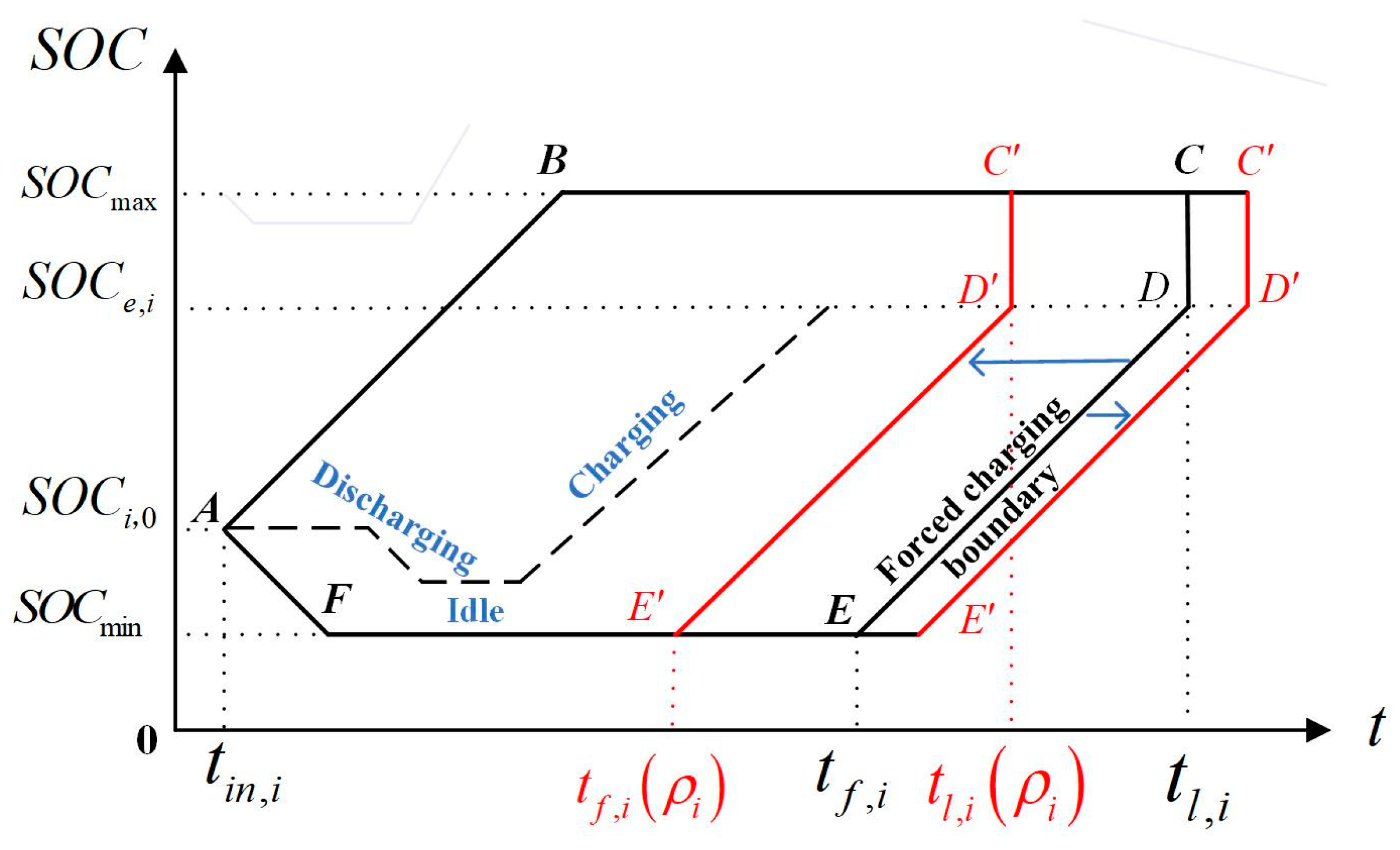
3.1. Individual EV Controllable Domain Model Based on Reliability Parameter Modification

EV participation in frequency regulation first needs to satisfy the charging demands of car owners. Based on this premise, car owners will consider EV participation in frequency regulation. This paper assumes that EVs that can satisfy the charging demands participate in frequency regulation. Based on the owner’s order information, this paper simulated the time tin,i, SOC, and reliability when EVs are connected to the power system, as well as the departure time tl,i and expected SOC set by EVs through Monte Carlo sampling.
In order to effectively control the charging and discharge process of an EV after it is connected to the charging pile, this paper considers the travel uncertainty of users based on the EV controllable domain [29] and proposes an individual EV controllable domain model based on the reliability parameter modification, as shown in Figure 2. When the ith EV is connected to the power system at time tin,i, the SOC of the EV battery level is SOC0,i. At the same time, EVs set the departure time tl,i and the lowest expected battery level SOCe,i when departing. SOCmin and SOCmax are the minimum and maximum allowable SOC values, respectively. Each EV connected to the power system is limited by the upper and lower boundaries of the controllable domain. When an EV touches the upper and lower boundaries of the controllable domain, the EV switches from the current state to the idle state, as shown by the dotted line in Figure 2, waiting for the scheduling of EVA. The controllable domain is represented by the upper boundary A-B-C; when the EV is connected to the power system, it will charge at the maximum charging power P max c until SOCmax is reached. The lower boundary A-F segment means that the EV will discharge at the maximum discharge power P max d once connected to the power system until SOCmin is reached. The lower boundary E-D segment means the EV is in a state of forced charging to satisfy the EV’s travel demand.
The actual departure time of the EV is uncertain, which leads to the inaccurate prediction of controllable capacity by EVA and the inability of users to satisfy their travel demands in terms of electricity. The reliability parameter ρi [30] (ρi is a statistical parameter measuring the reliability of electric vehicles, defined as Formula (1), mainly by analyzing the actual residence time and set residence time of each EV) is introduced to describe the uncertainty of EV departure time, as shown in Equation (2). Therefore, the charging cycle of the EV becomes [tin,i, tl,i(ρi)], and the upper and lower boundaries of the controllable domain based on reliability correction become A-B-C′ and A-F-E′-D′, respectively. Solving the uncertainty of EV departure time tf,i(ρi) can not only satisfy the travel demands of users to the maximum extent but also improves the accuracy of EVA’s prediction of frequency regulation reserve capacity to satisfy the frequency regulation demands of the power system. T i , t f is defined as time t, the time required for the ith EV to charge to SOCe,i with power P max c [15], as shown in Formula (3). The forced charging boundary E′-D′ in Figure 2 is calculated by tf,i(ρi), as shown in Formula (4).
ρ i = T i a ¯ T i d ¯
t l , i ( ρ i ) = t i n , i + ρ i · ( t l , i t i n , i )
T i , t f = Q · ( S O C e , i S O C i ( t ) ) η c · P max c
t f , i ( ρ i ) = t l , i ( ρ i ) T i , t f
where T i a ¯ and T i d ¯ represent the historical actual residence time and historical planned residence time of the ith EV, respectively, and the value of reliability ρi can be obtained by calculating historical data; tl,i(ρi) represents the departure time based on the reliability modification; Q is the battery capacity of the EV; ηc represents the charging efficiency of the EV; and tf,i(ρi) is the time for forced charging. When ttf,i(ρi), the EV enters an uncontrollable state to satisfy the EV’s travel demands and is charged with power P max c until the EV’s departure.
The charging and discharging power of an EV should satisfy the following conditions:
χ i ( t ) · P max d P i ( t ) χ i ( t ) · P max c
χ i ( t ) = 1 , t [ t i i n , t l , i ( ρ i ) ] χ i ( t ) = 0 , t [ t i i n , t l , i ( ρ i ) ]
where χi(t) = 0 means the EV is not connected to the charging station, and χi(t) = 1 means the EV is connected to the charging station. Pi(t) is the charging and discharging power of the ith EV at time t, Pi(t) > 0 means the EV is in a charging state, and Pi(t) < 0 means the EV is in a discharge state. P max d is the maximum discharge power of the EV connected to the power system.
The SOC variation pattern for an EV is shown below,
S O C i ( t + 1 ) = S O C i ( t ) + P i ( t ) η c Δ t Q , 0 < P i ( t ) P max c S O C i ( t ) , P i ( t ) = 0 S O C i ( t ) + P i ( t ) Δ t η d Q , P max d P i ( t ) < 0
where SOCi(t) and SOCi(t + 1) are the SOC values of the ith EV in time period t and time period t + 1, ηd represents the discharge efficiency of the EV, and Δ t is the time interval of two adjacent time periods.

3.2. EV State Grouping Based on Controllable Domain

3.2.1. EV State Grouping

To quantify the urgency of EV charging time, this paper defines the remaining departure time T i , t l based on reliability correction, and the time condition information of the reference power charging time T i , t b and t as state groups, as shown in Equations (8) and (9).
T i , t l = t l , i ( ρ i ) t
T i , t b = Q · ( S O C e , i S O C i ( t ) ) η c · P b w
where T i , t l and T i , t b are, respectively, the remaining network time of the ith EV at time t and the time required to charge the EV with reference power P b w .
Based on the individual EV controllable domain model based on reliability correction, the states of the EV connected to the power system are divided into FCS, WV2GS, and SV2GS according to T i , t l , T i , t b , and SOC, as shown in Equation (10). To prevent EV overcharge and discharge, the EV’s status is updated every 1 min. The FCS of the EV is reached with great urgency. EVA will not assign frequency regulation tasks or initiate the FCS of an EV with power P max d until controllable demands are met. The WV2GS of EVs has strong charging urgency and weak frequency regulation ability. When EVs do not participate in frequency regulation, they are charged with reference charging power, as shown in Equation (11). The SV2GS of EV charging urgency is weak, and the frequency regulation ability is very strong, which is the main part of frequency regulation. When there is no frequency regulation task, the EV is charged with the reference charging power, as shown in Equation (11). Figure 3 shows the state grouping of an EV, where tb,i(ρi) is the boundary moment, as shown in Equation (12).
FCS , T i , t l T i , t f   or   S O C i ( t ) [ S O C min , S O C max ] WV 2 GS ,   T i , t f T i , t l T i , t b   &   S O C i ( t ) [ S O C min , S O C max ] SV 2 GS ,   T i , t b T i , t l   &   S O C i ( t ) [ S O C min , S O C max ]
P b , i = P b w , WV 2 GS P b s , SV 2 GS & S O C i ( t ) S O C e , i 0 , SV 2 GS & S O C i ( t ) > S O C e , i
t b , i ( ρ i ) = t l , i ( ρ i ) T i , t b
where tb,i(ρi) is the transfer time of SV2GS and WV2GS for the ith EV under the current SOC state; P b s is the reference power of the EV in SV2GS when it fails to satisfy the charging demands.

3.2.2. Determining EV Cluster Frequency Regulation

Figure 4 shows the adjustable capacity of an EV under controllable state, where the left and right side of the coordinate axis are the upward and downward controllable capacity of the EV under SV2GS and WV2GS, respectively, P i u p (t) and P i d o w n (t), as shown in Equations (13) and (14).
P i u p ( t ) = P max d P b , i , SV 2 GS 0 P b , i , WV 2 GS
P i down ( t ) = P max c P b , i ,   SV 2 GS P max c P b , i ,   WV 2 GS
where i refers the EV number in the cluster, and P i u p (t) and P i d o w n (t), respectively, refer to the upward and downward controllable capacity provided by the ith EV at time t.
According to the controllable capacity of individual EVs, EVA calculates the overall controllable capacity P t u p and the lower controllable capacity P t d o w n , respectively, as shown in Equations (15) and (16). EVA reports the controllable capacity P t u p and P t d o w n to the power system dispatching center. The power system dispatching center allocates frequency regulation tasks according to the frequency regulation requirements of the system and the controllable capacity reported by EVA.
P t u p = i = 1 N c o P i u p ( t )
P t d o w n = i = 1 N c o P i d o w n ( t )
where P t u p and P t d o w n , respectively, represent the overall upper and lower controllable capacity that the EV cluster can provide at time t, and Nco is the number of EVs in a controllable state at time t.

4. FR Power Allocation Strategy Based on State Grouping and Priority List

4.1. The FR Task of EVA

Compared with traditional thermal power frequency regulation units, EVs can respond to automatic generation control (AGC) frequency regulation signals quickly and accurately. The combined frequency regulation of EVs and thermal power units can solve problems such as the insufficient frequency regulation accuracy of thermal power units and insufficient frequency regulation capacity of a single EV resource [31]. In the frequency regulation control strategy, the thermal power unit normally responds to the AGC signal, and the EV is responsible for responding to part P t d e of the actual output deviation from the AGC signal of the thermal power unit [32], as shown in Formula (17). The frequency regulation task assigned to the EV by the dispatching center will not exceed its controllable capacity, as shown in Equation (18).
P t d e = P t G P t A G C
P t r e s = P t u p ,   P t d e < P t u p P t d e ,   P t u p P t d e P t d o w n P t d o w n ,   P t d e > P t d o w n
where P t d e is the response deviation of the thermal power unit, and P t d e > 0 represents the excessive output of the unit, which requires the EV to perform downward frequency regulation to increase the total charging power. P t d e < 0 indicates that the output of the frequency regulation unit is insufficient, and the EV demands to perform upward frequency regulation to reduce the total charging power. P t d e = 0 indicates that the EV is not required to participate in frequency regulation. P t G and P t A G C are the actual output of the unit and the frequency regulation signal of AGC at time t, respectively, and P t r e s is the frequency regulation power that the EV demands to respond to.

4.2. Frequency Regulation Priority Parameter

After receiving frequency regulation task P t r e s , EVA obtains the sequence of the EVs participating in frequency regulation according to frequency regulation priority parameter Γi,t. Γi,t comprehensively considers EV frequency regulation ability, charging urgency, and EV reliability information, which can be defined by reliability parameter ρi, frequency regulation ability parameter αi,t, and charging urgency parameter βi,t, as shown in Equation (19).
Γ i , t = ρ i · α i , t + β i , t

4.2.1. Frequency Regulation Capability Parameter

The frequency regulation capability parameter αi,t is used to describe the frequency regulation capability of EV i at time t. The frequency regulation capability is characterized by the relative position of the SOC in the controllable domain SOCe,i and the lower boundary, which is defined by Equation (20). The higher the value of αi,t, the stronger the upturn ability of the EV. On the contrary, the lower the αi,t value, the stronger the downmodulation ability of the EV.
α i , t = S O C i ( t ) S O C min S O C e , i S O C min

4.2.2. Charging Urgency Parameter

The charging urgency parameter βi,t is used to describe the relative level of charging urgency of the ith EV at time t among all EVs. It is defined by Equation (21), and the larger the value of βi,t, the smaller the probability of an EV entering the forced charging state and the stronger its upward frequency regulation ability.
β i , t = t f , i ( ρ i ) t max i = 1 N a l l t f , i ( ρ i ) t

4.3. FR Power Allocation of an EV

4.3.1. FR Priority List

The numbers of all the EVs in the controllable state are arranged by Γi,t from high to low to obtain the control priority list Lup. Sequence the numbers of all controllable EVs from low to high according to Γi,t to obtain the control priority list Ldown [24], as shown in Equation (22).
L up = ( c 1 , , c k , , c N co ) L d o w n = ( d 1 , , d h , , d N co )
where ck is the number of the kth EV in Lup; dh is the number of EV h in Ldown. Lup and Ldown satisfy the constraint as in the formula.
Γ t c 1 Γ t c k Γ t c N c o Γ t d 1 Γ t d h Γ t d N c o

4.3.2. Response Sequence and Response Capacity of EV

EVA determines the EVs participating in frequency regulation according to the priority list, status grouping, and P t r e s , and divides frequency regulation up and frequency down into two response levels.
(1) When P t r e s < 0 requires upward frequency regulation, that is, to reduce the total EV charging power, EVA compares P t r e s with the boundary value of the response level to determine the response level, as shown in Equation (24), and then responds in turn according to priority list Lup until the number of EVs Nre in response meet the constraint of Equation (25).
P t r e d m P t , 1 u p P t , 1 u p < P t r e d m P t u p
Upregulated response 1: Switch the EVs of SV2GS to the idle state in turn according to Lup, until the frequency modulation requirement is met;
Upregulated response 2: Based on the upregulation response 1, the EVs of WV2GS are switched to the idle state in sequence according to Lup; the EVs of SV2GS are switched to the power- P max d discharge state in sequence according to Lup.
k = 1 N r e P c k u p P t r e s k = 1 N r e 1 P c k u p < P t r e s
where P c k u p is the response capacity of the kth EV, and Nre is the number of EVs participating in the response.
(2) When the frequency demands to be adjusted downward, that is, to increase the total EV charging power, EVA compares P t r e s with the boundary value of the response level to determine the response level, as shown in Equation (26), and then responds in turn according to priority list Ldown until the number of EVs in response meets the constraint of Equation (27). The frequency regulation priority list and frequency regulation task allocation strategy is shown below
P t r e s P t , 1 d o w n P t , 1 d o w n < P t r e s P t d o w n
Downregulated response 1: Adjust the EVs of WV2GS from power to P max c according to Ldown;
Downregulated response 2: Based on the first step, adjust the EVs in the SV2GS from power P b c to power P max c .
h = 1 N r e P d h d o w n P t r e s h = 1 N r e 1 P d h d o w n < P t r e s

5. Results and Analysis

5.1. Simulation Model and Parameters

In order to verify the effectiveness of the frequency regulation control strategy proposed in this paper, a power system model including EVs and conventional units is taken as an example for simulation analysis, as shown in Figure 5. The simulation time is 10:00–22:00. The relevant parameters of the system frequency regulation model [24] and EV model [15] are shown in Table 2. In this paper, the Monte Carlo method [28] was used to simulate the driving behavior and SOC changes in 1000 EVs based on the driving rules and the Beijing Traffic Development Annual Report [33]. Considering the volatility of load and new energy generation, the unbalanced power of the system is simulated based on a white-noise model [23], as shown in Figure 6.

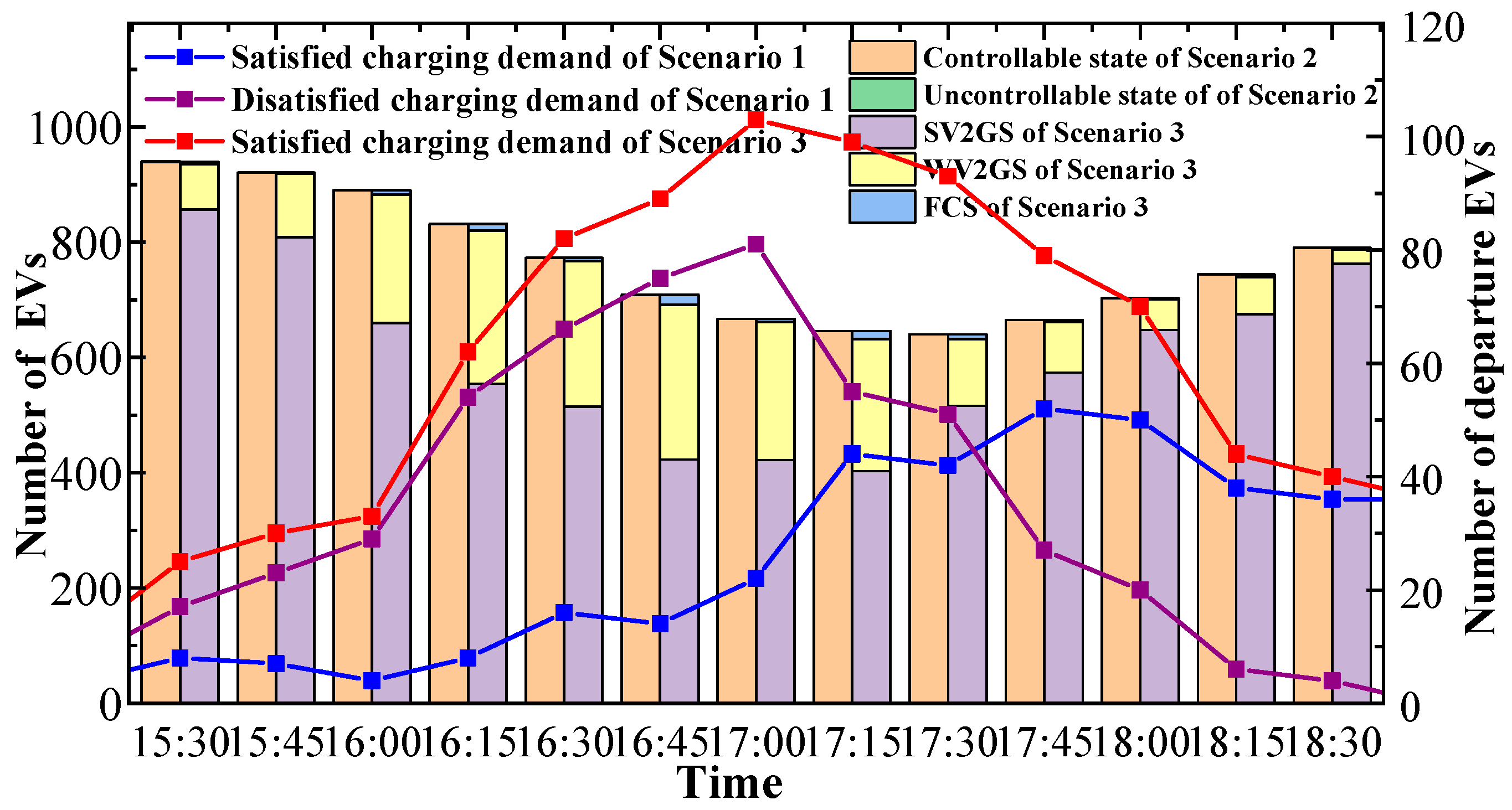
5.2. Results Analysis

Figure 7 shows the system frequency deviation between EVs not participating in frequency regulation and EVs participating in frequency regulation with the proposed control strategy. The Root Mean Square (RMS) of the system frequency deviation between EVs participating in frequency regulation with the proposed control strategy and EVs not participating in frequency regulation is 0.0359 and 0.0587 Hz, respectively. All the frequencies are within the safe range of 50 ± 0.5Hz. The proposed control strategy of EV participation in frequency regulation can effectively improve the system frequency quality and assist thermal power units to participate in the system frequency regulation service.

5.3. Contrastive Analysis

In order to compare the advantages of EV participation in the frequency regulation control strategy proposed in this paper, the following three scenarios are set for comparative analysis:
Scenario 1: The uncertainty of EV departure time is not taken into account, and the remaining parts are controlled according to the control strategy proposed in this paper;
Scenario 2: Considering the uncertainty of EV departure time, EV state grouping is not carried out, and frequency regulation is carried out for the rest of the parts according to the control strategy in this paper;
Scenario 3: Considering the uncertainty of EV departure time, follow the control strategy proposed in this paper.
Figure 8 shows the frequency regulation task received by EVA and the frequency regulation capacity in different scenarios. During the period approaching the departure time (15:30, 18:30), the downward frequency regulation of scenario 3 increased by 2.76% and 42.73% compared with scenario 1 and scenario 2, respectively. We compare the SOC data of EVs obtained from the simulation model with SOCe set by the car owner to obtain EV quantity data satisfying the charging demands, as shown by the broken line section in Figure 9. With the continuous departure of EVs, the frequency regulation of the EV cluster decreases with the increase in the number of departing EVs. Compared with Scenario 1, the number of EVs satisfying the charging demands of users in Scenario 3 increased by 132.75%. Considering the uncertainty of user travel, the departure time can be modified according to the reliability parameter ρi of EV historical charging habits. The departure time tl,i(ρi) modified by reliability parameter ρi can not only satisfy the charging demands of users when an EV has departed in advance but also accurately calculate the real-time controllable capacity of the EV.
The bar chart section in Figure 9 shows the number of EVs in different states during the departure period in Scenario 2 and Scenario 3. The total number of EVs reaches the minimum value of 640 during the 17:30–17:45 time period. In the figure, the number of EVs switched to the state of forced charging is small, which can avoid the impact of the increase in total EV power on the system load at the moment approaching departure. In Scenario 3 of Figure 9, the number of EVs in the WV2GS increases with the increase in time. As EV departure time approaches, in order to satisfy EV users’ charging demands, EVA adjusts the strong and weak V2G states according to the EV SOC level and charging urgency and changes the benchmark charging power Pb,i to make the frequency regulation change. Therefore, the frequency regulation in Scenario 3 in Figure 8 is greater than that in Scenario 2. In Scenario 2, at 15:45, 16:27, 17:00, and other times, the phenomenon that the adjustable downward capacity cannot satisfy the frequency regulation task affects the frequency regulation quality, while in Scenario 3, which considers controllable state grouping, the phenomenon that the frequency regulation cannot satisfy the frequency regulation task does not occur, so it has high frequency regulation capability.
In the time period (18:30, 22:00) shown in Figure 8, the downward frequency regulation and upward frequency regulation of Scenario 3 increased by 19.87% and decreased by 19.13%, respectively, compared with that of Scenario 2. The downward frequency regulation decrease in this period may not satisfy the frequency regulation requirements. In Scenario 3, EVs select appropriate benchmark charging power according to state grouping of SOC and charging urgency, thus increasing the downward frequency regulation of EVA. The change in upward frequency regulation does not affect the frequency regulation demands of the power system, because the upregulated capacity can satisfy the frequency regulation demands at this time.
To compare the influence of frequency regulation sequence parameters on EV participation in frequency regulation, Scenario 4 is added to this paper.
Scenario 4: Considering the uncertainty of EV departure time, EV states are grouped according to the method presented in this paper, frequency regulation sequence parameters proposed in reference [24] are adopted, and frequency regulation is performed for the rest of the parts according to the control strategy presented in this paper.
Figure 10 shows the SOC changes in EV in Scenario 3 and Scenario 4 during the first access. It can be seen from the figure that compared with Scenario 3, the priority list of EV participation in frequency regulation is determined according to the control parameters in Scenario 4, which makes the SOC of an EV in the cluster tend to be consistent, ignoring the influence of charging urgency on EV frequency regulation priority. Compared with Scenario 3, the number of EVs entering the state of forced charging increases by 136.26%. In the time period of 14:00–16:30 near departure in Figure 11, the total power of the EV cluster in Scenario 3 is reduced by 17.67% compared with Scenario 4, which can reduce the impact of EV load on the power system.

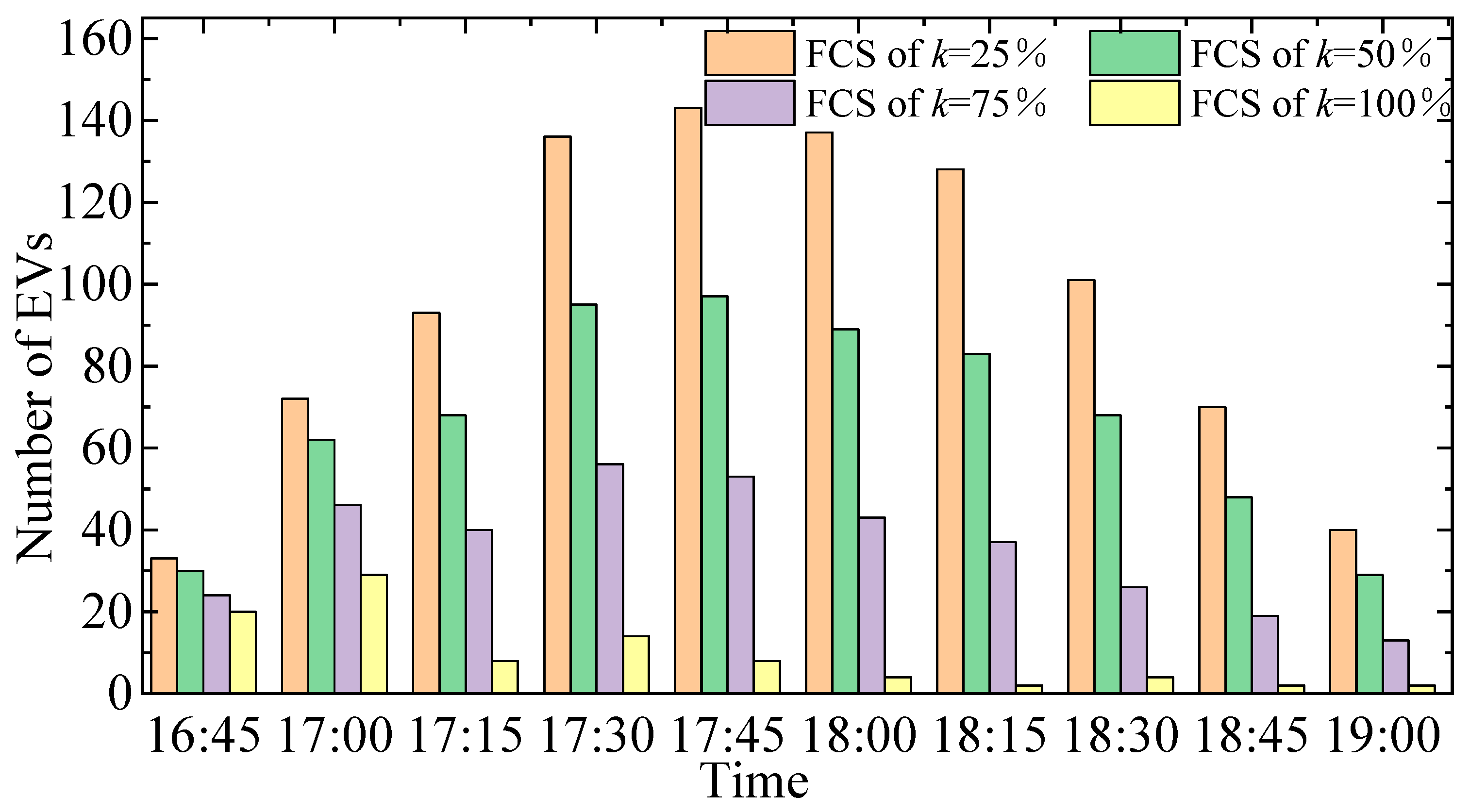
5.4. Sensitivity Analysis

Reliability will affect EVs’ on-network time, frequency regulation, and whether the charging demands of users can be met, as well as change the proportional coefficient k of the EV cluster considering the uncertainty of users’ travel. The frequency regulation of an EV cluster when k = 25%, k = 50%, k = 75%, and k = 100%, the number of EVs in EV charging demand, and the number of EVs in forced charging state are discussed, respectively.
Figure 12 shows the frequency regulation of an EV cluster under different proportional coefficients. With the increase in k value, the frequency regulation of k = 50%, k = 75%, and k = 100% increases by 3.28%, 5.96%, and 7.06%, respectively, compared with that under k = 25%. The main reason is that the modified departure time considers the uncertainty of user travel. Adjust the state grouping according to the charging urgency, so that EVs can select the appropriate reference power to charge in a timely manner. When an EV can provide the largest frequency regulation, so with an increase in k, the frequency regulation of the EV cluster also increases.
Figure 13 shows how EVs satisfy users’ charging demands during departure with different proportion coefficients. With the increase in the proportion of k, the number of EVs satisfying users’ charging demands when k = 50%, k = 75%, and k = 100% increases by 26.30%, 53.89%, and 82.03%, respectively, compared with that when k = 25%. The main reason is that considering the uncertainty of users’ travel, the departure time will be corrected, and timely adjustment of the state can satisfy the charging demands of users even if they depart in advance. Moreover, according to the data in Figure 14, the number of EVs in forced charging gradually decreases with the increase in proportion of how considered the uncertainty of user travel is in the EV cluster. Considering the uncertainty of user travel can reduce the number of EVs entering the state of forced charging and alleviate the impact of EV disorderly charging on the power system load.

6. Conclusions

In this paper, an EV secondary frequency regulation control strategy considering the uncertainty of user travel is proposed. Firstly, the individual controllable EV domain model based on reliability parameter modification is constructed. Then, the state grouping of EVs is introduced and the frequency regulation of EVA is determined according to the state grouping. Finally, the priority list of EV participation in frequency regulation is determined by the EV charging urgency parameter and frequency regulation ability parameter. On this basis, a frequency control strategy based on EV state grouping and priority list is proposed, and a simplified frequency regulation model of a power system is used to verify the effectiveness of the proposed frequency regulation control strategy.
The proposed frequency regulation control strategy can carry out fine modeling of EVs and fully excavate EV frequency regulation ability according to EV information state grouping, which can satisfy the charging demands of car owners and the frequency regulation demands of power systems even when car owners travel with uncertainty. This frequency regulation control strategy can improve the accuracy of EVA’s prediction of controllable capacity, control EV charging and discharging sequence in an orderly way according to state information when an EV is involved in frequency regulation, reduce the impact of EVs’ disorderly charging on the power system, ease the power system’s frequency regulation pressure, and ensure the safe and stable operation of the power system. Future work will further study the relevant factors and correlation of EV users’ willingness to participate in frequency regulation and analyze the economy of EV participation in frequency regulation from the perspective of users and agents.

Author Contributions

Conceptualization, X.D. and Y.M.; methodology, X.D. and Y.M.; software, X.D. and Y.M.; validation, X.D., Y.M. and X.Y.; formal analysis, X.Y. and X.W.; investigation, Y.R. and X.Z.; resources, X.D.; data curation, X.D. and Y.M.; writing—original draft preparation, Y.M.; writing—review and editing, X.D., Y.M., X.W. and Y.R.; visualization, X.Y.; supervision, X.D. and X.Y.; project administration, X.D.; funding acquisition, X.D. All authors have read and agreed to the published version of the manuscript.

Funding

This work is supported by the National Natural Science Foundation of China (52277116), the Science and Technology Project of Hebei Education Department (QN2022026), and the Natural Science Foundation of Hebei Province (E20202131).

Data Availability Statement

The study did not report any data. Additional data can be provided upon email request to the corresponding author.

Conflicts of Interest

The authors declare no conflict of interest.

References

  1. Rahimi, T.; Ding, L.; Kheshti, M.; Faraji, R.; Guerrero, J.M.; Tinajero, G.D.A. Inertia response coordination strategy of wind generators and hybrid energy storage and operation cost-based multi-objective optimizing of frequency control parameters. IEEE Access 2021, 9, 74684–74702. [Google Scholar] [CrossRef]
  2. Miller, N.W.; Shao, M.; Venkataraman, S.; Loutan, C.; Rothleder, M. Frequency response of California and WECC under high wind and solar conditions. In Proceedings of the 2012 IEEE Power and Energy Society General Meeting, San Diego, CA, USA, 22–26 July 2012; pp. 1–8. [Google Scholar]
  3. Hui, H.; Ding, Y.; Song, Y. Modeling and control offlexible loads for frequency regulation services considering compensation of communication latency and detection error. Appl. Energy 2019, 250, 161–174. [Google Scholar] [CrossRef]
  4. Mishra, D.K.; Złotecka, D.; Li, L. Significance of SMES Devices for Power System Frequency Regulation Scheme considering Distributed Energy Resources in a Deregulated Environment. Energies 2022, 15, 1766. [Google Scholar] [CrossRef]
  5. Liu, S.; Xie, X.; Yang, L. Analysis, modeling and implementation of a switching bi-directional buck-boost converter based on electric vehicle hybrid energy storage for V2G system. IEEE Access 2020, 8, 65868–65879. [Google Scholar] [CrossRef]
  6. Zhong, J.; He, L.; Li, C.; Cao, Y.; Wang, J.; Fang, B.; Zeng, L.; Xiao, G. Coordinated control for large-scale EV charging facilities and energy storage devices participating in frequency regulation. Appl. Energy 2014, 123, 253–262. [Google Scholar] [CrossRef]
  7. Fan, Y.; Zhang, L.; Xue, Z. Reactive Power Compensation Technology Based on V2G. Power Grid Technol. 2013, 37, 307–311. [Google Scholar]
  8. Wu, X.; Xie, X.; Lin, X. A model of regional power market where electric vehicles provide backup service. Autom. Electr. Power Syst. 2016, 40, 71–76. [Google Scholar]
  9. Cai, G.; Jiang, Y.; Huang, N. Charging and discharging optimization Scheduling of large-scale electric vehicles under Power Demand Response Mechanism based on multi-agent double-layer game. In Proceedings of the CSEE 2022, Lisbon, Portugal, 10–12 April 2022; pp. 1–16. [Google Scholar]
  10. Neofytou, N.; Blazakis, K.; Katsigiannis, Y.; Stavrakakis, G. Modeling vehicles to grid as a source of distributed frequency regulation in isolated grids with significant RES penetration. Energies 2019, 12, 720. [Google Scholar] [CrossRef]
  11. Ma, X.; Zhao, J.; Zhao, M. Adaptive Control Strategy of Electric Vehicles Participating in Primary Frequency Regulation of Power Grid. In Proceedings of the 2021 IEEE 4th International Electrical and Energy Conference (CIEEC), Wuhan, China, 28–30 May 2021; pp. 1–6. [Google Scholar]
  12. Liu, H.; Hu, Z.; Song, Y. Decentralized vehicle-to-grid control for primary frequency regulation considering charging demands. IEEE Trans Power Syst. 2013, 28, 3480–3489. [Google Scholar] [CrossRef]
  13. Peng, C.; Zou, J.; Lian, L. Dispatching strategies of electric vehicles participating in frequency regulation on power grid: A review. Renew. Sustain. Energy Rev. 2017, 68, 147–152. [Google Scholar] [CrossRef]
  14. Li, J.; Ai, X.; Hu, J. Modeling and Control Strategy of Electric Vehicle Participation in Power Grid secondary Frequency regulation. Power Grid Technol. 2019, 43, 495–503. [Google Scholar]
  15. Deng, Q.; Zhang, Y.; Li, T. Hierarchical Distributed Frequency Regulation Strategy of Electric Vehicle Cluster Considering Demand Charging Load Optimization. IEEE Trans. Ind. Appl. 2022, 58, 720–731. [Google Scholar] [CrossRef]
  16. Xia, S.; Bu, S.; Luo, X. An autonomous real-time charging strategy for plug-in electric vehicles to regulate frequency of distribution system with fluctuating wind generation. IEEE Trans. Sustain. Energy 2018, 9, 511–524. [Google Scholar] [CrossRef]
  17. Yao, W.; Zhao, J.; Wen, F. Frequency regulation Strategy for Electric Vehicles in Centralized Charging Mode. Autom. Electr. Power Syst. 2014, 38, 69–76. [Google Scholar]
  18. Han, S.; Han, S.; Sezaki, K. Development of an optimal vehicle-to-grid aggregator for frequency regulation. IEEE Trans. Smart Grid 2010, 1, 65–72. [Google Scholar]
  19. Wang, X.; Zhou, B.; Zhang, B. Research on electric vehicles providing frequency regulation strategy based on hierarchical control. Electr. Meas. Instrum. 2018, 55, 8–15. [Google Scholar]
  20. Razmi, P.; Rahimi, T.; Sabahi, K.; Gheisarnejad, M.; Khooban, M.H. Adaptive fuzzy gain scheduling PID controller for frequency regulation in modern power system. IET Renew. Power Gener. 2022, 1–16. [Google Scholar] [CrossRef]
  21. Tripathy, S.; Debnath, M.K.; Kar, S.K. Optimal Design of PI/PD Dual mode Controller based on Quasi Opposition Based Learning for Power System Frequency Control. e-Prime-Advances in Electrical Engineering. Electron. Energy 2023, 4, 100135. [Google Scholar]
  22. Du, M.; Niu, Y.; Hu, B.; Zhou, G.; Luo, H.; Qi, X. Frequency regulation analysis of modern power systems using start-stop peak shaving and deep peak shaving under different wind power penetrations. Int. J. Electr. Power Energy Syst. 2021, 125, 106501. [Google Scholar] [CrossRef]
  23. Michigami, T.; Ishii, T. Construction of fluctuation load model and dynamic simulation with LFC control of DC power system and frequency converter interconnection. In Proceedings of the IEEE/PES Transmission and Distribution Conference and Exhibition, Yokohama, Japan, 6–10 October 2002; pp. 382–387. [Google Scholar]
  24. Li, C.; Zhou, Y.; Xu, Z. System Frequency control strategy based on Energy Efficiency power plant for electric Vehicles. J. Electr. Power Syst. Autom. 2019, 31, 68–74. [Google Scholar]
  25. Yu, Z.; Gong, P.; Wang, Z. Real-Time Control Strategy for Aggregated Electric Vehicles to Smooth the Fluctuation of Wind-Power Output. Energies 2020, 13, 757. [Google Scholar] [CrossRef]
  26. Zhang, H.; Hu, Z.; Xu, Z. Evaluation of achievable vehicle-to-grid capacity using aggregate PEV model. IEEE Trans. Power Syst. 2017, 32, 784–794. [Google Scholar] [CrossRef]
  27. Wang, M.; Mu, Y.; Shi, Q.; Jia, H. Electric Vehicle Aggregator Modeling and Control for Frequency Regulation Considering Progressive State Recovery. IEEE Trans. Smart Grid 2020, 11, 4176–4189. [Google Scholar] [CrossRef]
  28. Luo, Z.; Hu, Z.; Song, Y. Optimal coordination of plug-inelectric vehicles in power grids with cost-benefit analysis—Part II: A casestudy in China. IEEE Trans. Power Syst. 2013, 28, 3556–3565. [Google Scholar] [CrossRef]
  29. Wang, M. State Space Model of Aggregated Electric Vehicles for Frequency Regulation. IEEE Trans. Smart Grid 2020, 11, 981–994. [Google Scholar] [CrossRef]
  30. Zhang, Q.; Li, Y.; Li, C. Grid frequency regulation strategy considering individual driving demand of electric vehicle. Electr. Power Syst. Res. 2018, 163, 38–48. [Google Scholar] [CrossRef]
  31. Xu, M.; Ai, X.; Fang, J. A two-stage stochastic Optimization Scheduling Model for electric vehicle and Unit Joint frequency regulation considering user Enthusiasm. Power Grid Technol. 2022, 46, 2033–2041. [Google Scholar]
  32. Zhao, Y.; Du, Y.; Li, H. Frequency Regulation Power Allocation Method for Electric Vehicles Coordinated with Thermal Power Units in AGC. In Proceedings of the 2022 5th International Conference on Energy, Electrical and Power Engineering (CEEPE), Chongqing, China, 22–24 April 2022; pp. 919–926. [Google Scholar]
  33. 2021 Beijing Transportation Development Annual Report. Available online: http://www.bjtrc.org.cn/List/index/cid/7.html (accessed on 1 June 2021).
Figure 1. Frame diagram of EV participating in frequency regulation.
Energies 16 03794 g001
Figure 2. Individual EV controllable domain model based on reliability correction.
Energies 16 03794 g002
Figure 3. EV state grouping based on controllable domain.
Energies 16 03794 g003
Figure 4. The controllable capacity of an EV in a controllable state.
Energies 16 03794 g004
Figure 5. Simplified frequency regulation model of the power system.
Energies 16 03794 g005
Figure 6. System unbalanced power.
Energies 16 03794 g006
Figure 7. System frequency deviation.
Energies 16 03794 g007
Figure 8. EV controllable capacity.
Energies 16 03794 g008
Figure 9. Number of EVs in different scenarios.
Energies 16 03794 g009
Figure 10. SOC curves of each EV in different scenarios.
Energies 16 03794 g010
Figure 11. Total power of EV clusters.
Energies 16 03794 g011
Figure 12. The controllable capacity of EVs under different proportional coefficient k.
Energies 16 03794 g012
Figure 13. The number of EVs that satisfy the charging demand of departure time with different proportional coefficients k.
Energies 16 03794 g013
Figure 14. The number of EVs in FCS under different proportion coefficients k.
Energies 16 03794 g014
Table 1. Different reference work comparison.
ReferenceIndividual EV ModelWhether to Consider UncertaintyEV Classification ParameterEV Response Sequence Parameter
[14]naive modelNoSOCSOB
[15]naive modelYesSOCRegulation unit time contribution
[24]naive modelNoSOCSOC
[25]complicated modelNoSOCControllable coefficient
[27]complicated modelYesRelaxation parameterState-space model
this articlecomplicated modelYesSOC and charging urgencyFR capability parameters and charging urgency parameters
Table 2. System model parameters [24] and EV parameters [15].
ParameterValueParameterValue
Req(p.u.)−0.09NEV1000
TG(s)0.2Driving speed (km/h)28.5
T1(s)2Energy consumption per 100 km (kW·h)15
T2(s)12Q (kW·h)40
TT(s)0.3 η c / η d 0.95
TEV(s)0.035Pbw/Pbs(kW)4/2
Heq(s)4.44Pcmax, Pdmax(kW)7
D(p.u.)1.0SOCmin/SOCmax0.3/0.9
ρiN(0.9, 0.1)SOC0 (p.u.)N(0.4, 0.05)
tinN(8.5, 0.52)SOCe (p.u.)N(0.8, 0.05)
tlN(17.5, 0.52)Commuting distance lnDS (km)N(17.9, 4.9)
Disclaimer/Publisher’s Note: The statements, opinions and data contained in all publications are solely those of the individual author(s) and contributor(s) and not of MDPI and/or the editor(s). MDPI and/or the editor(s) disclaim responsibility for any injury to people or property resulting from any ideas, methods, instructions or products referred to in the content.

