Article

Cracking Analysis of a Brass Clamp Mounted on the Main Transformer in the Power Grid System

1
State Grid Sichuan Electric Power Research Institute, Chengdu 610000, China
2
College of Electrical Engineering, Sichuan University, Chengdu 610000, China
*
Author to whom correspondence should be addressed.
Energies 2023, 16(8), 3460; https://doi.org/10.3390/en16083460
Submission received: 31 January 2023 / Revised: 18 February 2023 / Accepted: 9 March 2023 / Published: 14 April 2023

Abstract

:
Cracking of conductive brass accessories in substations causes overheating or an open circuit, seriously affecting the safe and stable operation of the power grid system. A deep understanding of failure mechanisms could provide more safety, as well as lower down costs and save time for the power grid system, which have been seldomly involved in the literature. This paper presents a cracking analysis of a brass clamp in service for seven years that is mounted on the main transformer. The fracture morphology, chemical composition, and metallographic structure of the brass clamp were systematically analyzed, and the stress conditions were obtained by finite element simulation. The clamp exhibits transgranular brittle fracture with high oxygen content in the fracture, containing a crack propagation along the Pb particle connecting pathways, and the stress concentration was confirmed at the crack position. It is concluded that the failure was a result of the stress corrosion cracking and excessive content of Pb. Suggestions were proposed to avoid malfunction of the main transformer caused by the clamp crack.

1. Introduction

Due to the unique combination of non-magnetism, good machinability, superior corrosion resistance [1], relative strength, higher thermal conductivity [2], electrical conductivity, formability [3], and low cost, brasses are widely used in drinking water distribution systems [4,5], heat-transfer units [2], and other industries for water filtration [6], elbow fitting [7], nuts [8], etc. Brasses are copper–zinc alloys with the Zn content between 5% and 40% [9]. According to the Cu-Zn phase diagram [10], alloys containing less than 35% Zn only form a single α phase, while adding an even higher Zn content can form a duplex α + β’ brasses. The α phase is a solid solution with Zn dissolving in Cu matrix, characterized by face-centered cubic lattice (FCC), and is essential for the corrosion resistance and cold workability of brasses. The Zn-rich β’ phase, an intermetallic compound, has a body-centered cubic structure (BCC), which can provide excellent plasticity, but exhibits a susceptibility to dezincification [11].
Properties can be effectively tuned by Zn content, dezincification inhibitors, the fraction, size and shape of phase, doping, etc. The dezincification behavior of low-Pb duplex brasses has been systematically studied by Michael et al. Results showed that in addition to less β’ phase fraction, a small α grain size with high aspect ratio can also improve the dezincification resistance [12]. Silicon brasses were investigated to increase strength or produce environment-friendly alloys with excellent dezincification resistance [4,13]. CuZn21Si3P forms a complex triple-phase, containing about 60% of α phase with some Si-rich κ (Cu8Zn2Si) phase and γ (Cu4ZnSi) phase. The selective Zn leaching is inhibited by the “phosphorous cycle” [13]. Karpagavalli et al. reported that with the addition of As, Sb, and P, the hardness and β’ phase fraction of brasses increase, while corrosion resistance decreases [14].
Lead is traditionally alloyed to brasses to improve the alloy machinability through lowering cutting forces, decreasing tool wear, and favoring chip breaking [15,16]. Lead has a very low solubility in copper and is dispersed as globules both at grain boundaries and within the matrix, creating discontinuities that promote the chip fragmentation. Moreover, it acts as a lubricant decreasing the friction coefficient between the tool and the alloys and reducing the cutting force and the tool wear rate [17]. The positive effect in machinability increases with Pd content and becomes saturated at 3% [18,19]. Beyond 3%, lead may cause shrinkage and hot tearing defects during casting. Moreover, it can exert little or some enhancement in the corrosion resistance of the alloy, which depends on the environment and composition [9,20].
The main categories of in-service failures for brass components include environmentally induced failures, cold deformation defects caused by severe plastic deformation, and thermal deformation faults generated during manufacture [21]. The two most common environmental failures in brass components are stress corrosion cracking (SCC) and dezincification corrosion. SCC is generally a result of the specific combined action of environmental and tensile stress. Dezincification corrosion is related with the selective leaching of Zn through cathodic dissolution in an electrochemical cell and is commonly inhibited by applying a Ni coating [12,13].
Case studies of broken brass components have been widely conducted, but it is noteworthy that failures are specific to different applications consisting of occasionally a dominant mechanism and sometimes a combination of mechanisms. The failure of CuZn21Si3P in aggressive tap water starts with the dezincification of the κ and γ phase [22]. Metcalfe et al. presented a SCC from the outside surface of a 45-degree bend copper fitting, which was in contact with the polyurethane insulation. The crack initially propagated through the intergranular path and transitioned to the transgranular path as the crack propagated toward the tube bore [7]. A new opinion was raised by Zhou et al. that the interaction of ant nest corrosion and stress corrosion cause the failure of copper tubes [2]. A stress induced brittle failure due to dezincification was investigated by Olofinjana et al. in a nickel coated brass dolphin striker [8].
Therefore, it is valuable to analyze the root cause of failures for every case when employing brass alloys to perform specific functions. This article aims to study the failure of brass clamps mounted on the main transformer in the power grid system, which have received relatively little attention in previous studies. The transformer, especially the 110 kV and above main transformer in the load center, is one of the most important pieces of equipment in the power grid system. The normal operation of its body and accessories is the premise for the safe and stable operation of power grids. The failure of components mounted on the main transformer may compromise the entire substation system, resulting in casualties and huge economic losses. This paper presents a cracking analysis of a Pb-brass clamp installed on the 110 kV main transformer that has been assembled to function and exposed in the moisture atmospheric for 7 years. The rated capacity and voltage of the transformer type SZ10-50000/110 are 50,000/50,000 kVA and 110 ± 8 × 1.25%/10.5 kV, respectively. The clamp, designed as a BDW-20/400 H62 casting brass, is a crucial metal connecting part of the main transformer current loop, linking a conductive rod in the bushing to busbar.

2. Materials and Methods

The cracking Pb-brass clamp was disassembled form the main transformer, to facilitate failure analyzing. Photos of the clamp in service and after disassembly were taken by an optical camera, as shown in Figure 1 and Figure 2. Dimension tests were conducted by a straight steel ruler and vernier caliper.
A scanning electron microscope (SEM, EVO MA10, Zeiss, Oberkochen, Germany) and energy dispersive spectrometer (EDS, X-act, Oxford, UK) were used to perform the fracture morphology and local chemical analyses, respectively. Section samples were machined across fractured areas by wire cutting, as shown in Figure 2f, and stacked on the SEM sample holder with a conducting adhesive. SEM images and EDS spectrum were obtained using an accelerating voltage of 20 kV at the working distance of 8.5 mm.
For the in-depth analysis, the clamp was cut perpendicularly toward the crack direction, and grinding and polishing were performed along the cross-section. A solution of 1 g of FeCl3 in 20 mL HCl with 100 mL H2O was elected as the etching solution according to the book of metallographic diagrams of metallic materials [23]. Optical metallographic structure was performed using optical microscopy (OM, BX51M, Olympus, Tokyo, Japan).
On the polished sections, Vickers hardness tests, using a diamond indenter, were conducted with an Innovatest Falcon450 microhardness tester under a 1 kgf, according to the range recommended [3]. The tester is equipped with high quality optical systems consisting of an objective lens with high magnification and high numerical aperture. Precise chemical analysis of the clamp was performed on the polished surface by an optical emission spectrometer (OES, S9 Atlantis, GNR, Novara, Italy).
The 3D geometry of the clamp was built using SolidWorks software. The stress analysis was carried out on COMSOL Multiphysics finite element simulation platform. The mesh refinement preset in the software was used, for which the edges around the breaking position of the clamp were properly densified to about 50 elements. The total number of mesh grids for the entire clamp varied within the range of 20,000 to 25,000 according to different geometry configurations.

3. Results

3.1. Chemical Examination

The design material of clamp is a H62 copper-zinc alloy, in which the Cu content is between 60.5% and 63.5%, according to the China National Standard of GB/T 5231-2001 [24]. The base material of failed clamp was analyzed by an optical emission spectrometer and illustrated in Table 1. It is indicated that the clamp is fabricated by lead brass with 2.5% Pb, which is inconsistent with the design requirements. Excessive lead content will reduce the elongation rate of copper alloy, which can be confirmed indirectly by succedent microhardness test.

3.2. Macroscopic Examination

The specific macro-appearance of the failed clamp is presented in Figure 2. The clamp is dark gray and contains three parts: a holding clip (A), ear plate (B), and terminal plate (C). A penetrative crack, lying in the junction between A and B and between B and C, expands from the outside to inside. The depth of crack is 12 mm and 14 mm at the top and bottom of the connecting region, respectively, indicating an incompletely fracture, as shown in Figure 2a–c. Furthermore, an ear plate deformation approximately 4° and an indentation near the bolt hole can be observed in Figure 2d,e. The high torque applied to the bolt of clamp could be the reason for these deformations.
The failed clamp was cut along the crack for a detailed Inspection of the fracture surface. As shown in Figure 2f, the fracture is basically flat with obvious corrosion traces, and the crack propagates from the top to bottom areas. No macroscopic fatigue features and plastic deformation are observed, exhibiting the characteristic of brittle fracture.

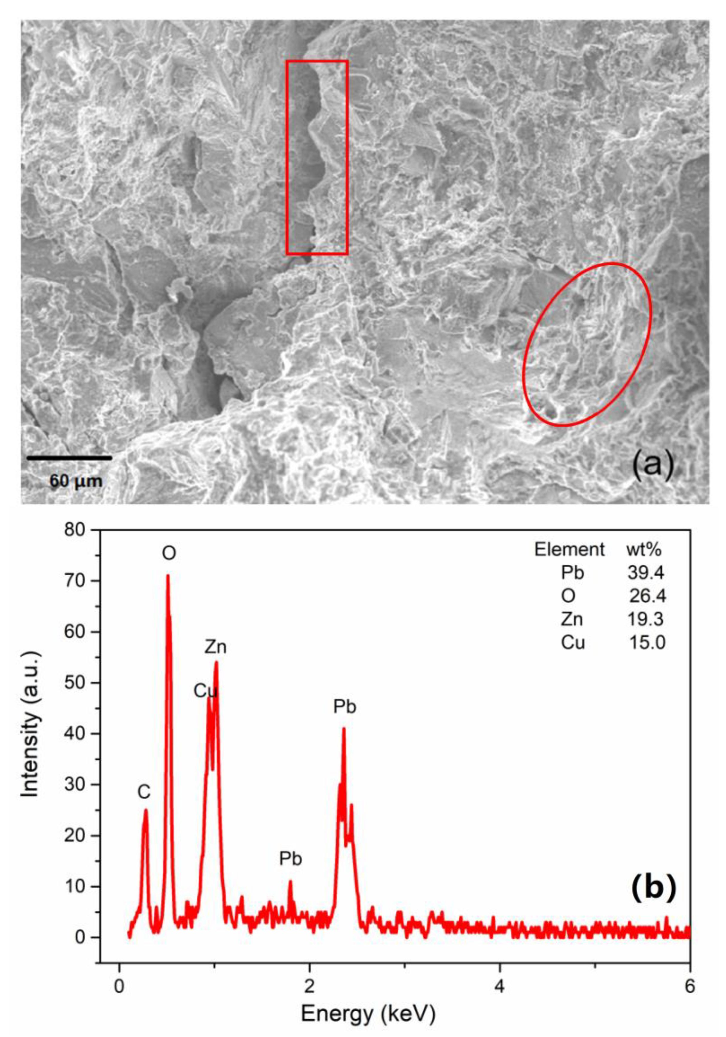
3.3. Microstructural Examination

Figure 3 shows local magnified SEM micrographs and the EDS spectrum of the fracture surface. The brittle nature of the failure can be further confirmed by the quasi-cleavage morphology and secondary cracks, which were marked by the rectangle and ellipse, respectively, in Figure 3a. No fatigue striations appear on the fracture surface, and the fatigue failure mechanism is not applicable in this case. The content of Pb in the fracture surface is about 39.4%, far above the detection value of base material mentioned in Section 3.1, indicating a crack propagation along the Pb particle connecting pathways. Figure 3b shows a high oxygen content, and it can be inferred that clamp was subjected to a severe corrosion by environmental media.

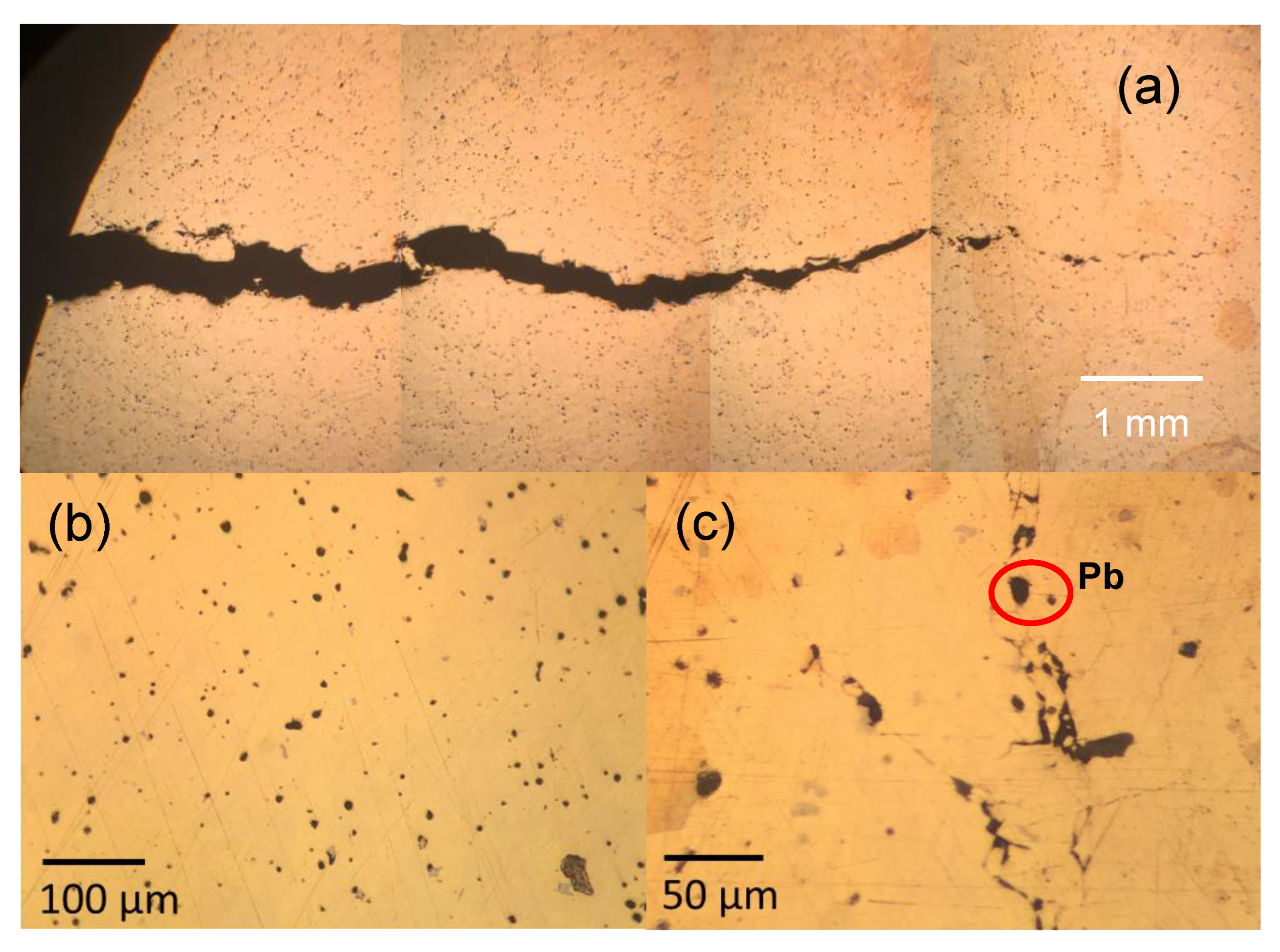
3.4. Metallographic Examination

The optical micrographs of unetched profile are exhibited in Figure 4. The crack propagation observed in Figure 4a confirms a brittle fracture with secondary cracks. Large amounts of black Pb particles are dispersed in the matrix with different sizes and shapes. It can be confirmed by different Pb contents measured by EDS in certain particles and matrices, which are 58.8% and 0%, respectively. Some small cracks along the particles are observed in local areas, as shown in Figure 4b,c, which are mainly influenced by casting and solidification conditions.
The microstructure is typically a mixture of bright flat-elongated α phase and “dark” β’ phase. Pb particles distribute inside the α phase or at the boundary of two phases, as shown in Figure 5a,b. The metallographic graphs on the cracking zone are presented in Figure 5c,d. The crack is propagating prevalently through the grains and Pb dispersoids, indicating a trans-granular fracture. Moreover, secondary cracks can be clearly presented in Figure 5c.

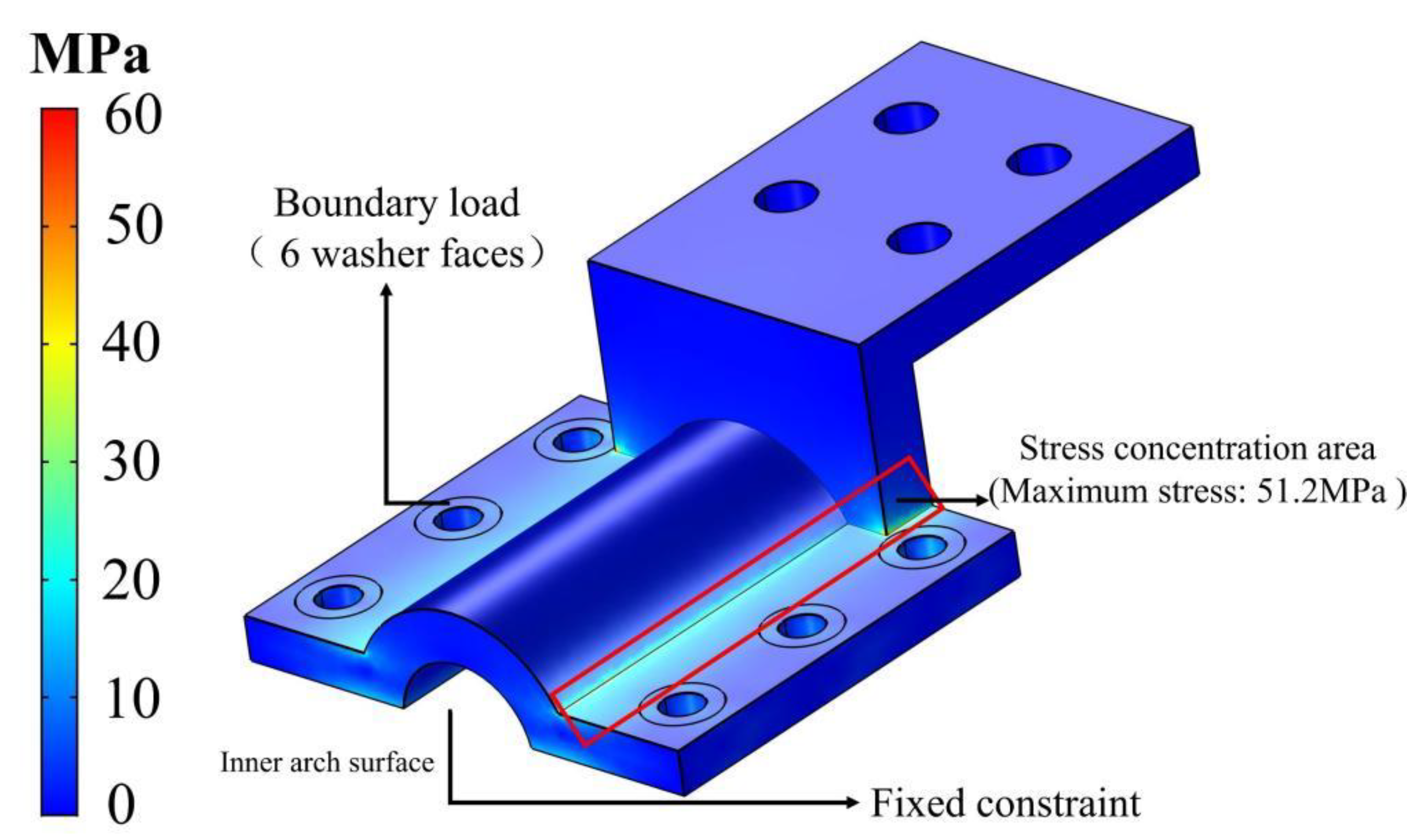
3.5. Stress Analysis

Measurements of hardness were taken on the cross-section in Figure 4. The average hardness is 120 HV, which is in accord with the values reported of CuZn39Pb3 leaded brass reported by Anagnostis et al. and higher than lead-free brasses (CuZn36 [25] and CuZn38 [26]). A ductility loss was induced owing to the Pb distribution in phase boundaries, which can lead to the minimization of grain boundary energy.
From the installation and operation status of the main transformer in Figure 1, the clamp is combined with the bushing conductive rod, and the holding ear needs to be fastened by bolts. The main crack lies on the junction of holding clip and ear plate, where residual stress may appear after casting, and stress concentration is easily caused under external force. In this case, a finite element model was established, and the stress conditions were analyzed.
The model was established as follows. First, the geometric model was constructed based on the actual size of the clamp. Then, the geometric model was imported into the simulation software to build the physical model, and the material parameters of the clamp were set (Young’s modulus of 1.08 × 10⁵ MPa, Poisson’s ratio of 0.30) [27]. Subsequently, according to the actual working condition of the clamp, the inner arch surface was applied with a fixed constraint, and a boundary load of 1000 N was applied to the washer faces at the six bolt holes, and the rest part was assigned with free boundary. Then, the tetrahedral mesh was adopted, which was refined until no obvious change of the stress distribution results. Finally, the steady-state calculation with the MUMPS algorithm with direct matrix decomposition was applied. It can be seen from Figure 6 that the Von Mises stress is mainly concentrated at the chamfer area, which therefore demonstrates that the fracture of the clamp is closely related to the stress concentration. Moreover, the maximum stress of 51.2 MPa does not exceed the yield strength of 92 MPa [27], which implies that the clamp maintains at the elastic state, and the cracking should not be originated from over stress.
Through proper geometry optimization, the stress concentration can be relieved. Since the stress of the clamp is mainly concentrated at the chamfer area, the stress distribution can be improved by filleting. Additionally, because the bolt is installed at the edge, the stiffness of the clamp can be improved by increasing the thickness of the middle circular arch to reduce the stress at the chamfer zone. To demonstrate this, a comprehensive optimization scheme was carried out. The chamfering radius was set to 1 mm, 2 mm, and 3 mm, respectively, and the arch thickness was set to two levels of 45 mm and 50 mm. As can be seen Figure 7, the maximum stress of the clamp can be reduced in comparison with that in Figure 6 by increasing the size of fillet and the thickness of the arch. Among them, when the chamfering radius is 3 mm and the curvature is 50 mm, the maximum stress of the clamp is only 25.6 MPa, which is 50% of the original one, demonstrating that the stress of clamp can be improved by a large degree.

4. Discussion

Three characteristic conditions are necessary for SCC to occur, which are the corrosion environment, the susceptible material, and the tensile stress [28]. The generation of SCC is mainly divided into three stages, namely, the initiation stage of crack or corrosion pit, the crack propagation stage before the crack source or corrosion pit reaches the ultimate strength stress value, and the final unstable fracture stage. In the crack initiation stage, three characteristic conditions interact with each other until the local conditions in the crack tip region reach a critical state that promotes the propagation of cracks. This stage is related with a period of time with no apparent crack growth. When the crack starts to propagate, the cracking rate is freelance of the applied stress intensity and usually appears as a “plateau”. The cracking rate in the final unstable fracture stage becomes fast and strongly dependent on the applied stress intensity. It is well known that usually SCC will not occur itself during a period of several years until the metallic engineering material suddenly fails and the time before cracking decreases with increasing the stress [29]. The clamp here has been used as a conductor on the 110 kV main transformer in Sichuan Province of China for 7 years before discovery of the cracking, allowing the hypotheses of a progressive damage mechanism rather than sudden overload. SCC is most encountered in the industrial environments that contain ammonia, nitrates, sulfates, citrate, etc. [7]. However, there are other reports of brasses even in pure water [30] or environments containing traces of water [31]. Rain is abundant in Sichuan, and the air humidity is frequently very high. Higher content O was detected in the fracture surface corrosion products. Therefore, in the present case study, the corrosive media producing SCC can be considered as H2O. Brasses containing more than 15% Zn were reported to be more susceptible to SCC, and the susceptibility increases with increasing Zn content [31]. The Zn content of the failed clamp in this case was 36.5%, which is far higher than 15%. According to the literature [32], SCC can occur even if the components experience tense stress, encompassing both applied and residual stress, much below the yield strength of the alloy. Due to the special structure of the clamp, residual stress and stress concentration can be easily formed after casting and under overload force, respectively. It can be preliminarily inferred that the clamp is cracked by stress corrosion under the combined effects of stress and a humid atmosphere.
The SCC type can be either intergranular or transgranular, depending on the component of the alloy, the nature of the environment [32], and the level of stress [7]. Pantazopoulos et al. reported an intergranular propagation crack with multiple secondary branches in a connector of a boiler tubing [33]. In a copper elbow fitting, the main fracture surface showed an intergranular path at the first third of its length and then followed a transgranular path as cracking propagated toward the tube bore [7]. The cracks propagating transgranular and intergranular corrosion occurred in the near surface area of copper–zinc alloys for the drinking water installation [34]. The mechanisms of SCC are still not well understood with disagreement as to the mechanism of cracking in a given system and confusion as to whether the mechanism varies from one system to another. Stress-sorption, film-rupture-metal dissolution, and the hydrogen-embrittlement mechanism are currently most actively used [29]. The present crack propagation of the failed clamp is perpendicular to the stress axis, and the fracture is transgranularly brittle with secondary cracks, which coincide with characteristics of SCC.
The clamp material of lead brass with 2.5% Pb cannot meet the design requirement of H62 brass. Furthermore, the content of the Pb at fracture is higher than in matrix, corresponding to a crack path propagating through particles. Although the machinability and abrasion resistance of brass can be improved by dissociative particles, ductility is reduced due to the liquid metal embrittlement [35,36]. Pb phases can weaken the interatomic bonds and destroy the continuity of substrate, providing a minimum resistance path for crack propagation. In other words, particles can serve as a pathway for crack initiation and propagation, as demonstrated in Figure 4 and Figure 5. Moreover, the stress concentration position in Figure 5 coincides with the crack position in Figure 1. Thus, the clamp failure in this work is caused by the synergistic effect of stress corrosion and excess lead. According to the stress distribution of the simulation results, it is found that the stress is mainly concentrated at the fracture. It can be concluded that reducing the stress at the fracture can reduce the risk of the clamp fracture. The structure can be improved by filleting at the fracture position to reduce stress concentration and by increasing the thickness of the clamp arch to improve the structural strength of the clamp.
Furthermore, many factors that affect SCC behaviors have been studied [28,37], such as composition, temperature, microstructure, and annealing. Among them, there is more attention toward the temperature influence of SCC on steels and alloys, but there is little research on the effect on copper–zinc alloys. According to the material nature, temperature has a different influence on the chemical reactions at the crack and the diffusion rate of corrosion products from the corrosion environment to the material. Tempered martensitic Type 403 stainless steel showed intergranular stress corrosion cracking in 0.1 M NaSO4 at temperatures of 75 °C and 100 °C but not at the lower temperatures of 25 °C and 50 °C [29]. The stress corrosion cracking resistance of two API X65 microalloyed steels has been evaluated by Fragiel et al. with different microstructures both at room temperature and 55 °C. Results showed that specimens at 55 °C had slightly lesser SCC threshold stress intensity and metallographic characteristics that illuminate the nature of the SSC mechanism in these steels. That is, the specimens were more susceptible to SSC at room temperature [37]. Umamaheshwer Rao et al. reported that quantitative measurements of crack growth rates in pre-cracked AA7079-T651 and AA7039-T651 aluminum alloys as a function of stress intensity and temperature have shown that increases in temperature decrease the crack growth rate and threshold stress intensity of SCC [28]. Both the flow of a large electric current and high ambient temperature in Sichuan could increase the service temperature of the clamp, which may accelerate SCC of the brass clamp and is worthy of further study.

5. Conclusions

In summary, cracking analysis of a brass clamp mounted on the main transformer in the power grid system was conducted, which has received little attention in the literature. Systematic experimental analysis of the fracture morphology, chemical composition, and metallographic structure was carried out, together with simulated stress conditions. A transgranular brittle fracture with high oxygen content was unveiled in the fracture, as well as a crack propagation along the Pb particle connecting pathways and the stress concentration confirmed at the crack position, from which stress corrosion cracking with transgranular brittle fracture was drawn. A humid corrosive environment, susceptible lead brass material, and large tensile stress induced during casting and installation can be the factors that cause stress corrosion cracking. Dissociative Pb particles in the matrix accelerate the crack growth rate as a pathway of crack propagation. Through simulation, a proper clamp geometric structure was proposed to decrease the probability of fracture failure.
In order to avoid similar accidents, the following suggestions are put forward: (i) well control the casting and installation process to reduce stress concentration prevent large stress at the junction zone of the clamp, (ii) the usage of alloys which are more resistant to SCC, And (iii) the improvement of the geometric structure of the clamp to reduce the stress concentration.

Author Contributions

Conceptualization, J.C. and L.W.; methodology, J.F. and F.W.; investigation, J.C. and Q.P.; writing—original draft preparation, J.C. and G.L.; writing—review and editing, L.W. and L.Z. All authors have read and agreed to the published version of the manuscript.

Funding

This research was funded by Science and Technology Project of State Grid Sichuan Electric Power Company, grant number 52199720003H.

Data Availability Statement

The data is unavailable due to privacy.

Conflicts of Interest

The authors declare no conflict of interest.

References

  1. Pilar Valles, M.; Pastor, A.; García-Martínez, M. Corrosion study of a water filter. Eng. Fail. Anal. 2022, 137, 106404. [Google Scholar]
  2. Zhou, J.; Li, Y.; Jing, T.; Sun, Z.; Ma, L. Interactive effect of ant nest corrosion and stress corrosion on the failure of copper tubes. Eng. Fail. Anal. 2018, 83, 9–16. [Google Scholar]
  3. Toulfatzis, A.; Pantazopoulos, G.; David, C.; Sagris, D.; Paipetis, A. Final Heat Treatment as a Possible Solution for the Improvement of Machinability of Pb-Free Brass Alloys. Metals 2018, 8, 8. [Google Scholar]
  4. Choucri, J.; Balbo, A.; Zanotto, F.; Grassi, V.; Touhami, M.; Mansouri, I.; Monticelli, C. Corrosion Behavior and Susceptibility to Stress Corrosion Cracking of Leaded and Lead-Free Brasses in Simulated Drinking Water. Materials 2022, 15, 144. [Google Scholar]
  5. Chang, L.; Lee, J.; Fung, Y. Prediction of lead leaching from galvanic corrosion of lead-containing components in copper pipe drinking water supply systems. J. Hazard. Mater. 2022, 436, 129169. [Google Scholar]
  6. Siu, K.; Kwok, J.; Ngan, A. Thermo-mechanical processing of brass components for potable-water usage increases risks of Pb leaching. Water Res. 2020, 186, 116414. [Google Scholar]
  7. Metcalfe, G.; Pearce-Boltec, N. Stress corrosion cracking of a copper elbow fitting. Eng. Fail. Anal. 2018, 90, 197–201. [Google Scholar] [CrossRef]
  8. Olofinjana, A.; Haque, R. Analysis of failure in a nickel coated brass dolphin striker Component. Eng. Fail. Anal. 2017, 72, 48–57. [Google Scholar] [CrossRef]
  9. Choucri, J.; Zanotto, F.; Grassi, V.; Balbo, A.; Touhami, A.; Mansouri, I.; Monticelli, C. Corrosion Behavior of Different Brass Alloys for Drinking Water Distribution Systems. Metals 2019, 9, 649. [Google Scholar]
  10. Lisenko, N.; Evans, C.; Yao, Y. Effect of brass composition and phases on stress corrosion mitigation by laser shock peening. Manuf. Lett. 2020, 23, 5–8. [Google Scholar]
  11. Galai, M.; Choucri, J.; Hassani, Y.; Benqlilou, H.; Mansouri, I.; Ouaki, B.; Ebn Touhami, M.; Monticelli, C.; Zucchi, F. Moisture content and chloride ion effect on the corrosion behavior of fitting brass (gate valves) used as a connection of PVC’s conduits in aggressive sandy soil. Chem. Data Coll. 2019, 19, 100171. [Google Scholar] [CrossRef]
  12. Moriarty, M.; Wu, Y.; Murray, T.; Hutchinson, T. The effect of phase fraction, size and shape on the dezincification of duplex brasses. Corros. Sci. 2021, 184, 109366. [Google Scholar] [CrossRef]
  13. Zhou, P.; Hutchison, M.J.; Erning, J.W.; Scully, J.R.; Ogle, K. An in situ kinetic study of brass dezincification and corrosion. Electrochim. Acta 2017, 229, 141–154. [Google Scholar]
  14. Karpagavalli, R.; Balasubramaniam, R. Influence of arsenic, antimony and phosphorous on the microstructure and corrosion behavior of brasses. J. Mater. Sci. 2007, 42, 5954–5958. [Google Scholar]
  15. Schultheiss, F.; Windmark, C.; Sjöstrand, S.; Rasmusson, M.; Ståhl, J. Machinability and manufacturing cost in low-lead brass. Int. J. Adv. Manuf. Technol. 2018, 99, 2101–2110. [Google Scholar] [CrossRef] [Green Version]
  16. García, P.; Rivera, S.; Palacios, M.; Belzunce, J. Comparative study of the parameters influencing the machinability of leaded brasses. Eng. Fail. Anal. 2010, 17, 771–776. [Google Scholar]
  17. El-Bahloul, A.M.; Samuel, M.; Fadhil, A.A. Copper-zinc-lead alloys, common defects through production stages and remedy methods. TOJSAT 2015, 5, 17–22. [Google Scholar]
  18. Vilarinho, C.; Davim, J.P.; Soares, D.; Castro, F.; Barbosa, J. Influence of the chemical composition on the machinability of brasses. J. Mater. Process. Technol. 2005, 170, 441–447. [Google Scholar]
  19. Felli, F.; Brotzu, A.; Pilone, D. Analysis of the fracture criticality of biphasic brass. Procedia Struct. Integr. 2016, 2, 2959–2965. [Google Scholar]
  20. Ismail, K.M.; Elsherif, R.M.; Badawy, W.A. Effect of Zn and Pb contents on the electrochemical behavior of brass alloys in chloride-free neutral sulfate solutions. Electrochim. Acta 2004, 49, 5151–5160. [Google Scholar]
  21. Pantazopoulos, G.A. A review of defects and failures in brass rods and related components. J. Fail. Anal. Prev. 2003, 3, 14–22. [Google Scholar] [CrossRef]
  22. Seuss, F.; Gaag, N.; Virtanen, S. Corrosion mechanism of CuZn21Si3P in aggressive tap water. Mater. Corros. 2017, 68, 42–49. [Google Scholar] [CrossRef]
  23. Li, J. Metallographic Diagrams of Metallic Materials; China Mechine Press: Beijing, China, 2006. [Google Scholar]
  24. GB/T 5231; State Standard of the People’s Republic of China, Wrought Copper and Copper Alloys Chemical Composition Limits and Forms of Wrought Products. Standards Press of China: Beijing, China, 2001.
  25. Toulfatzis, A.I.; Pantazopoulos, G.A.; Paipetis, A.S. Fracture behavior and characterization of lead-free brass alloys for machining applications. J. Mater. Eng. Process. 2014, 23, 3193–3206. [Google Scholar] [CrossRef]
  26. Liu, L.; Wang, J.; Zhou, J. Characterization and analysis on micro-hardness and microstructure evolution of brass subjected to laser shock peening. Opt. Laser Technol. 2019, 115, 325–330. [Google Scholar] [CrossRef]
  27. Jiao, Z.; Zheng, X.; Dai, K. Cause of Fracture on transformer drainage hoop clamp of current transformers. PTAC (Part A PHYS.TEST.) 2021, 57, 50–54. [Google Scholar]
  28. Rao, A.; Vasu, V.; Govindaraju, M.; Srinadh, K. Stress corrosion cracking behaviour of 7xxx aluminum alloys: A literature review. Trans. Nonferr. Metal Soc. 2016, 26, 1447–1471. [Google Scholar] [CrossRef]
  29. Loto, C.A. Stress corrosion cracking: Characteristics, mechanisms and experimental study. Mor. J. Chem. 2017, 5, 622–640. [Google Scholar] [CrossRef]
  30. Layer, J.; Adler, T.; Ahmed, R.; Aliya, D.; Antolovich, S.D.; Baggerly, R.G. ASM handbook-failure analysis and prevention. ASM Int. 2002, 11, 14–65. [Google Scholar]
  31. Lynch, S. Failures of metallic components involving environmental degradation and material- selection issues. Corros. Rev. 2017, 35, 191–204. [Google Scholar] [CrossRef]
  32. Elayaperumal, K.; Raja, V.S. Corrosion Failures Theory, Case Studies, and Solutions; Revie, R.W., Ed.; Wiley Series in Corrosion; John Wiley & Sons, Inc.: Hoboken, NJ, USA, 2015; pp. 96–97. [Google Scholar]
  33. Pantazopoulos, G.A.; Toulfatzis, A.I. Failure analysis of a machinable brass connector in a boiler unit installation. Case Stud. Eng. Fail. Anal. 2013, 1, 18–23. [Google Scholar] [CrossRef] [Green Version]
  34. Brandl, E.; Malke, R.; Beck, T.; Wanner, A.; Hack, T. Stress corrosion cracking and selective corrosion of copper-zinc alloys for the drinking water installation. Mater. Corros. 2009, 60, 251–258. [Google Scholar] [CrossRef]
  35. Johansson, J.; Persson, H.; Ståhl, J.E.; Zhou, J.M.; Bushlya, V.; Schultheiss, F. Machinability evaluation of low-lead brass alloys. Procedia Manuf. 2019, 38, 1723–1730. [Google Scholar] [CrossRef]
  36. Schultheiss, F.; Johansson, D.; Bushlya, V.; Zhou, J.; Nilsson, K.; Ståhl, J.E. Comparative study on the machinability of lead-free brass. J. Clean. Prod. 2017, 149, 366–377. [Google Scholar] [CrossRef]
  37. Fragiel, A.; Serna, S.; Malo-Tamayo, J.; Silva, P.; Campillo, B.; Martínez-Martínez, E.; Cota, L.; Staia, M.H.; Puchi-Cabrera, E.S.; Perez, R. Effect of microstructure and temperature on the stress corrosion cracking of two microalloyed pipeline steels in H2S environment for gas transport. Eng. Fail. Anal. 2019, 105, 1055–1068. [Google Scholar] [CrossRef]
Figure 1. (a) The brass bushing clamp mounted on the main transformer. (b) General view of the cracked brass clamp.
Energies 16 03460 g001
Figure 2. (a) Macro-appearance, (b,c) crack depth, (d) deformation, (e) indentation, and (f) fracture of the failed clamp.
Energies 16 03460 g002
Figure 3. Local magnified SEM micrographs (a) and EDS spectrum (b) of the fracture surface.
Energies 16 03460 g003
Figure 4. Optical micrographs of the cross-section morphology. (a) crack propagation, (b) black Pb particles, (c) small cracks along the Pb particles.
Energies 16 03460 g004
Figure 5. The metallographic figures of failed clamp on the (a,b) uncracking zone and the (c,d) cracking zone.
Energies 16 03460 g005
Figure 6. Simulated stress distribution of the clamp.
Energies 16 03460 g006
Figure 7. Results of the comprehensive optimization: (a) fillet of 1 mm, outer arch thickness of 45 mm; (b) fillet of 1 mm, outer arch thickness of 50 mm; (c) fillet of 2 mm, outer arch thickness of 45 mm; (d) fillet 2 mm, outer arch thickness of 50 mm; (e) fillet of 3 mm, outer arch thickness of 45 mm; (f) fillet of 3 mm, outer arch thickness of 50 mm. The values in brackets are the respective maximum stress.
Energies 16 03460 g007
Table 1. Chemical analysis of failed clamp (wt.%).
ElementCuZnPbSnAlSbPFe
Detection value 58.836.52.50.90.50.070.01-
Standard value60.5–63.5Surplus0.08----0.08
Disclaimer/Publisher’s Note: The statements, opinions and data contained in all publications are solely those of the individual author(s) and contributor(s) and not of MDPI and/or the editor(s). MDPI and/or the editor(s) disclaim responsibility for any injury to people or property resulting from any ideas, methods, instructions or products referred to in the content.

