1. Introduction
Particle migration in non-Newtonian fluids occurs in nature and many practical applications, such as chemical, mechanical, medical, and biological processes, so the dynamics of particle migrating in non-Newtonian fluids has received great attention. For example, blood flowing in the micro-circulation system includes the highly deformable red blood cells, which could transport oxygen and cause blood to have non-Newtonian characteristics [
1]. Particle focusing in the microfluid device is an essential step before detecting, counting, analyzing, and sorting particles in the applications [
2,
3,
4]. Hinder particle adhesion to the wall is important for the precious samples [
5]. It also has applications in medical diagnostics, therapeutics [
6], cell biology, and solar energy—for instance, the platelets are transfused to the patients during surgery; the cells are isolated to reduce the heterogeneity of the sample in order to study the characteristics of cells [
7]; the particles are transferred from suspending medium to the others for washing or coating; and the metallic or non-metallic particles are mixed into the fluid of a solar thermal collector to improve the thermophysical property, enhance the efficiency of the renewable energy, and provide net environmental benefits [
8].
Given the various applications described above, many scientists have investigated the particle migration in non-Newtonian fluids by using its rheological property and manipulated particles to migrate in an expected way, which did not work in Newtonian fluids. A particle in a pipe flow of Newtonian fluids would migrate to the lateral position between the wall and center of the pipe, and the particle of a different size would migrate to a different lateral position. Such migration phenomenon is not obvious for the submicron or nanoscale particles. Therefore, some scientists focused on the particle lateral migration in non-Newtonian fluids for improving separation efficiency of particles. Yang et al. [
9] revealed experimentally that there were many equilibrium positions, such as centerline and corners along the lateral direction under only viscoelastic effect in a rectangular microchannel. Wang et al. [
10] revealed numerically that the particle would migrate to the center or the closest corner of the channel depending on the initial position, and these conclusions were the same as the experimental results [
9] and the numerical results. [
11]. What is more, the particle would more likely migrate to the corner as the Weissenberg number increases. D’Avino et al. [
12] performed a two-dimensional simulation by neglecting the inertia effect and considering the viscoelastic effect alone; the results showed that the particle would move towards the closest wall in all situations, and there existed three regimes related to the particle–wall distance. D’Avino et al. [
13] performed a three-dimensional simulation and found that wall confinement and viscoelasticity would induce particle migration. Caserta et al. [
14] conducted an experiment and confirmed the above two numerical results. Liu et al. [
15] showed that the particle always migrated towards the wall regardless of changes in fluid viscosity. The shear-thinning property, wall confinement, and Weissenberg number all facilitated the particle move to the wall.
When considering both effects of fluid inertia and elasticity, Wang et al. [
10] indicated that the particle would move to the center of the shorter walls in Giesekus fluids. Raffiee et al. [
16] performed the numerical simulation and found that under the condition of large elasticity and high inertial, the particle would aggregate to the off-center point along the axis, which was the same as the experimental results [
17]. Jiang et al. [
18] also found the particle focusing at the channel centerline, and they indicated that the large flow velocity and particle size could accelerate the particle focusing. Huang et al. [
19] simulated numerically the particle migration in a two-dimensional Couette flow to study the inertia and elastic effect and found that the inertia caused the particle to move away from the wall, and the particle migration was controlled by the elastic normal stress. Liu et al. [
20] studied numerically the migration of particles in a 3-D shear flow of Giesekus fluids and found that the particle migration could be classified into two patterns, i.e., “returning” and “passing”. The separatrix between these two patterns was dependent on the Weissenberg number and the shear-thinning effect. For three particles, the trajectory of two particles on both sides was different from that of the intermediate particle. The phenomenon of abnormal migration tended to be obvious with increasing the shear-thinning effect, solvent viscosity, and the block ratio but with decreasing the elastic effect [
21]. Liu et al. [
22] found that the elastic effect accelerated a variation in particle trajectory from the “returning” to the “passing” pattern when the elasticity number was large, while the inertial effect was just the opposite. A large extensional force caused two particles to pass over each other. Wall confinement accelerated a variation in particle trajectory from the “passing” to the “returning” pattern. Liu et al. [
23] studied the migration of ellipsoidal particles in a confined shear flow of Giesekus fluids and found that the particle trajectory depended on initial orientation and position. The separatrix between the “returning” and “passing” pattern decreased with the increase in the Weissenberg number. The evolution of particle orientation depended on the initial orientation. The evolution of the particle orientation became slower with the increase in Weissenberg number.
For a confined shear flow, the migration direction and lateral equilibrium position of particles are related to the initial lateral position y0 of particles, while the value of y0 is related to the fluid property and blocking ratio. So far, the authors have not seen any report on the influence of fluid property and blocking ratio on y0 when a particle moves in a confined shear flow of Giesekus fluid. Therefore, the purpose of this study is to investigate the migration direction (towards the center line or wall) for the particle with initial lateral y0, determine the critical point yc of particle moving towards the center line or wall, and analyze the effect of viscosity ratio, shear-thinning parameter, Weissenberg number, and blocking rate on the value of yc.
2. Equations and Numerical Method
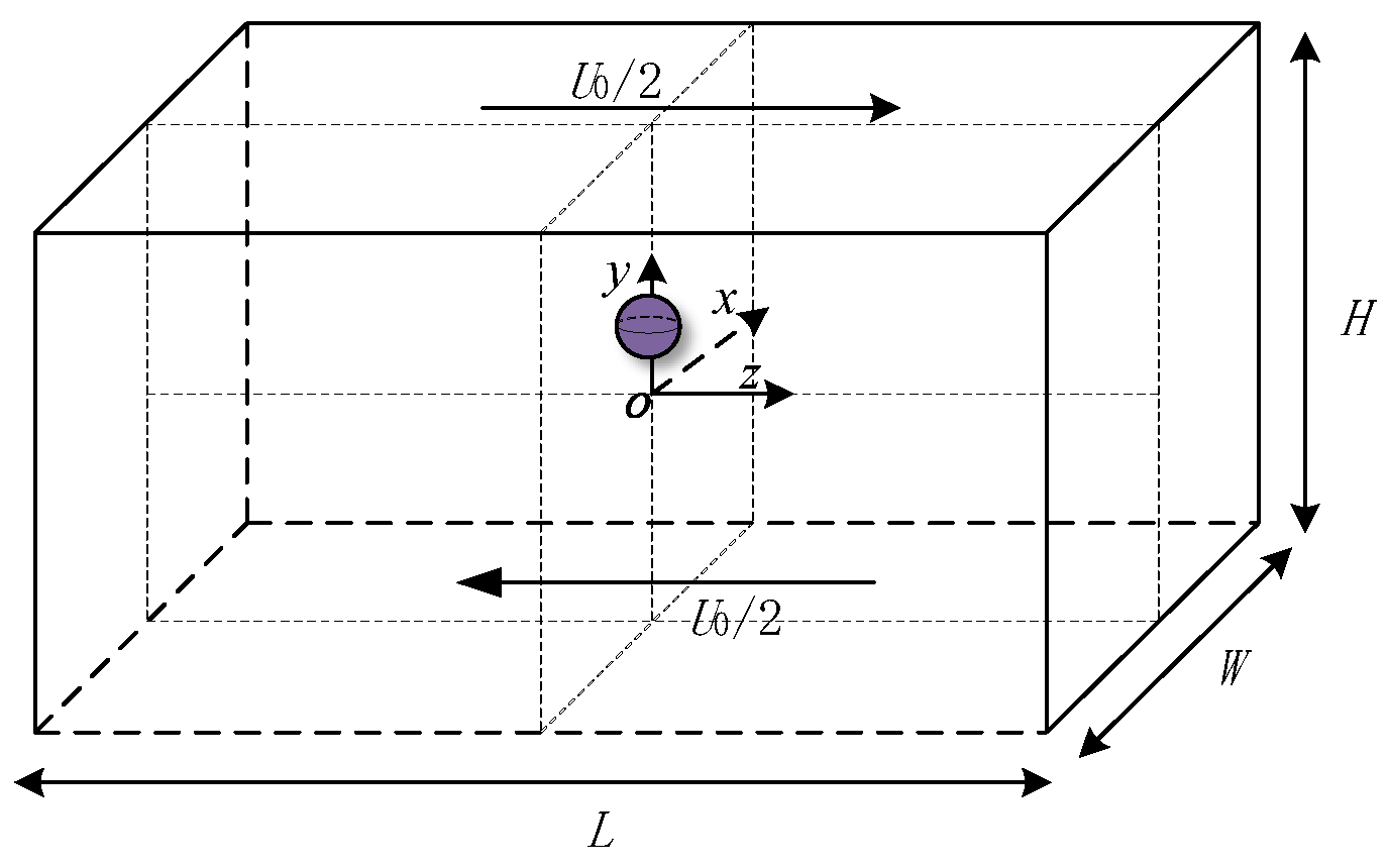
The system is shown in
Figure 1, where a particle with diameter of
d migrates in a confined shear flow of viscoelastic Giesekus fluid.
W,
L, and
H are used to represent the width, length, and height of the simulation domain, respectively. The origin of coordinates
O is at the center of the simulation domain. Two planes move in parallel with the opposite direction at velocity of
U0/2, so the shear rate of the flow is
0/
H. The blocking rate is
β =
d/
H.
The numerical simulation is performed using the direct forcing/fictitious domain (DF-FD) method. The principle of DF-FD is that the space occupied by the particle is assumed to be filled with fluid (fictitious fluid) and a pseudo force acts on the particle to force the fictitious fluid to satisfy the constraint condition of rigid-body motion.
The fluid density and particle density are
ρf and
ρp, respectively; the viscosity from the contribution of non-Newtonian fluid and solvent viscosity are
μp and
μs, respectively; the particle volume and moment of inertia are
Vp and
Jp, respectively; and the particle velocity and angular velocity are
Up and
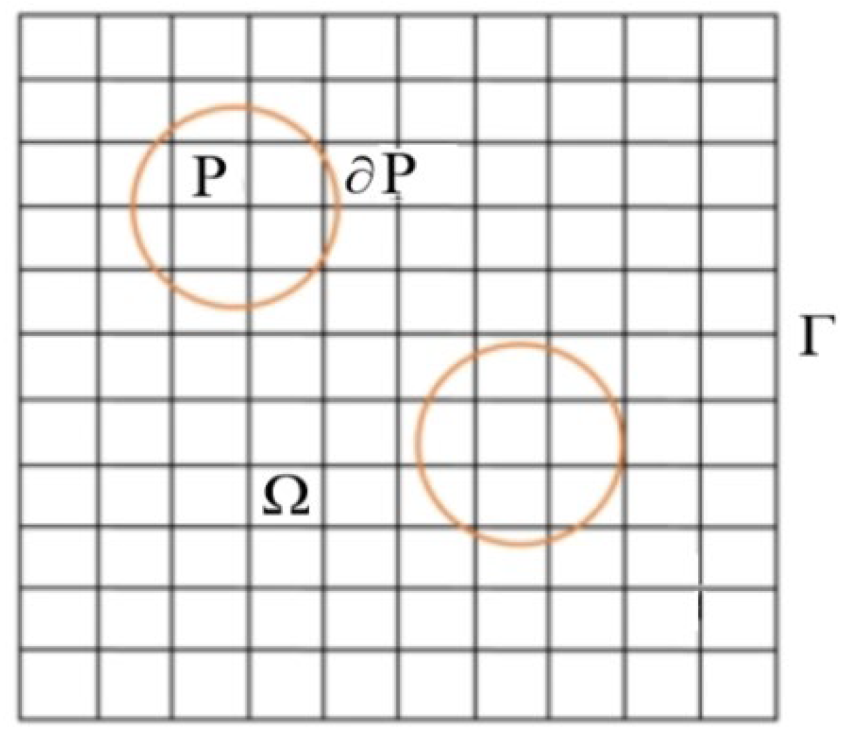
ωp, respectively. P and Ω are used to represent the particle domain and whole simulation domain, respectively, consisting of particle and fluid as shown in
Figure 2, where ∂P is the boundary of particle.
2.1. Fluid Equations
In
Figure 2, the area Ω
f occupied by fluid is Ω
f = Ω − P. For incompressible flow, the fluid satisfies the continuity and momentum equations:
in which
ρf,
u, and
σ are the fluid density, velocity, and stress tensor, respectively. According to the principle of DF-FD, it is assumed that the area occupied by the particle is filled with fluid, and a virtual volume force
λ is used to ensure the virtual fluid satisfies the condition of rigid-body motion. Therefore, by extending the fluid area from Ω
f to the entire calculation area Ω, the control equations satisfied by the flow in the area Ω can be written as:
where
r is the position vector; the virtual volume force
λ is exerted on the particle, i.e.,
λ ≠ 0 in particle area P, and
λ = 0 in the fluid area Ω
f. For incompressible flow, ▽∙
σ = −▽
p +
μ▽
2u (
p and
μ are the fluid pressure and viscosity, respectively).
2.2. Particle Equations
The motion of particle can be divided into translation and rotation, which can be described by the Newton’s second law:
where
m is the particle mass;
J is the rotational inertia of particles;
g is acceleration of gravity;
ρr =
ρp/ρf is the particle/fluid density ratio; and
n is the outer normal direction of particle surface.
In particle area P, integrating Equation (4) and
r × Equation (4) and substituting it into Equations (6) and (7), respectively, then combining with Equation (5), we have:
2.3. Combined Equations
Using length
H, velocity
U0, time
H/
U0, pressure
ρfU02, and pseudo body force
ρfU02/
H as characteristic quantities to dimensionalize the equation, we have the following combined dimensionless continuity and momentum equations:
and constitutive equation of Giesekus fluids:
in which
μr =
μs/
μ0 is the viscosity ratio, with
μ0 being the total zero shear rate viscosity (
μ0 =
μs +
μp); the Reynolds number is Re =
ρfU0H/μ0; the Weissenberg number is Wi =
λtU0/
H, with
λt being the fluid relaxation time;
B is the configuration tensor and included in the fluid stress
τ = μp(
B −
I)/
λt;
Vp* =
Vp/
H3 is the particle volume;
J* =
J/
ρpH5 is the dimensionless moment of inertia; and the mobility parameter α quantifies the degree of shear-thinning.
2.4. Sub-Problems
A fractional-step time approach is applied to decompose Equations (10)–(15) into the following three sub-problems.
Spatial discretization is performed using the projection approach based on finite difference in a uniform half-staggered grid, and all spatial derivatives are discretized using the second-order central difference.
- (2)
for particle
Upn+1,
ωpn+1,
λn+1, and
un+1:
in which
Upn+1 and
ωpn+1 can be calculated directly;
λn+1 and
un+1 are defined at the Lagrangian and Eulerian nodes, respectively:
u is transformed from Eulerian to Lagrangian nodes using the tri-linear interpolation function, and
λ is transformed from Lagrangian to Eulerian nodes.
- (3)
constitutive equation for
B:
When solving Equation (23), the scheme of first-order, central difference, and the third-order up-winding MUSCL are used for time, velocity gradient, and convective term, respectively.
2.5. Boundary Condition
The no-slip boundary condition is used at the wall and the particle surface, and the periodic condition is used at the streamwise (z) and crosswise (x) directions.
For a particle moving towards the wall, the simulation would stop when the particle’s center is d/2 away from the wall. To balance calculation accuracy and efficiency, we set L = 2H, the grid size is 1/128, and the time step is 5×10⁻⁴. The independence test of grid and time step size are conducted by changing grid size from 1/136 to 1/120 and time step from 2 × 10⁻⁴ to 8 × 10⁻⁴, respectively. When all normalized residuals for each quantity are less than 10−5, the calculation is considered convergent. The numerical simulation is completed using a self-compiled program.
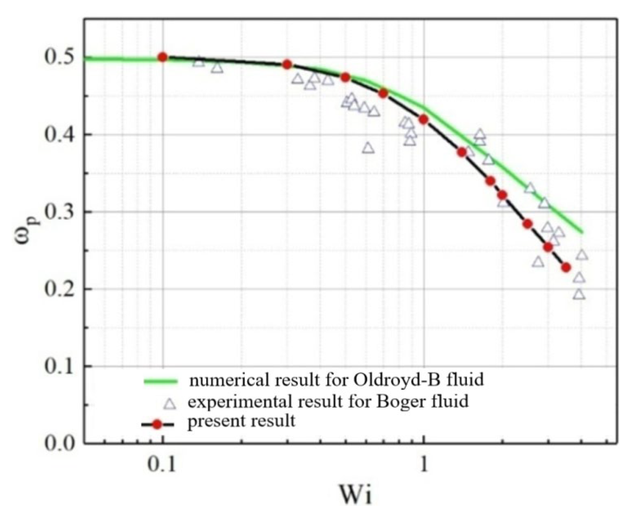
2.6. Validation
For verifying the feasibility of the method used here, we compared the present numerical results of particle angular velocity in a three-dimensional shear flow of an Oldroyd-B fluid, with the numerical results using the finite-element method and experimental data for the Boger fluid [
24] as shown in
Figure 3. It can be seen that the three match well.
3. Results and Discussion
The initial position of the particle is expressed as (x0, y0, z0), and the particle is at rest at the initial time. The particle migration direction (towards the center line or wall) is studied for different y0, and the critical value yc (dividing point of particle moving towards the center line and wall) of y0 is determined. In the simulation, we find that the critical value yc is 0.146 under the condition of μr = 0.7, α = 0.1, Wi = 0.3, and β = 0.2. When y0 < 0.146, the particle will migrate towards the central line, otherwise towards the wall. However, when one of μr, α, Wi, or β changes, yc will change; in other words, μr, α, Wi, and β have an effect on the value of yc. The effect is discussed below.
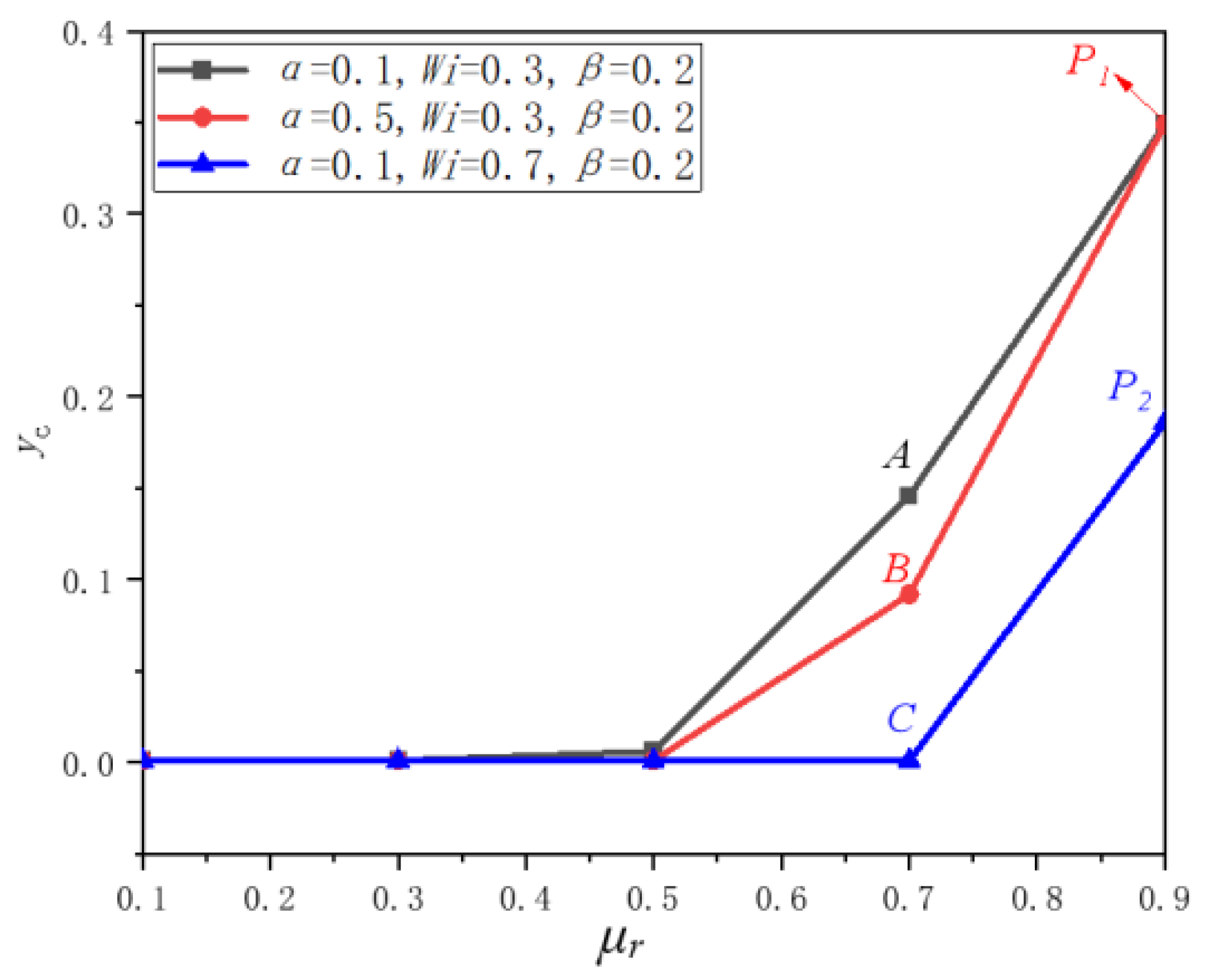
3.1. Effect of the Viscosity Ratio μr on the Critical Value yc
Figure 4 displays the relationship between
yc and
μr. We can see that when
μr ≤ 0.5, the values of
yc are almost 0 in all cases, i.e., regardless of the value of initial lateral position
y0, the particle will migrate towards the wall. When
μr > 0.5, the values of
yc increase with increasing
μr, and some particles will migrate towards the center line with the increase in
μr. For example, the particle with
yc < 0.186 (Point P
2) at
μr = 0.9,
α = 0.1, and Wi = 0.7 will migrate towards the center line. Therefore, the particle is more likely to migrate towards the center line in the high viscosity ratio
μr. When
μr > 0.5, the values of
yc are dependent on
α and Wi. For fixed
α, the value of
yc rises with the decrease in Wi; for fixed Wi, the value of
yc rises with decreasing
α, that is, the particle is more likely to migrate towards the center line at small Wi and
α.
The pressure contours for the three cases in
Figure 4 are shown in
Figure 5. The pressure is normalized with the average pressure, and positive and negative values indicate the pressures that are greater than or less than the average pressure. The figure shows the pressure distribution of a certain instantaneous flow, and the subsequent movement of particle is determined by the force acted upon the particle by the fluid that is linked to the instantaneous pressure distribution. The particle will migrate towards the region with lower pressure at the next moment. Comparing
Figure 5a–c, we can see that the pressure distributions of the three cases are similar, indicating that
α and Wi have little influence on the pressure distribution at the same
β and
μr.
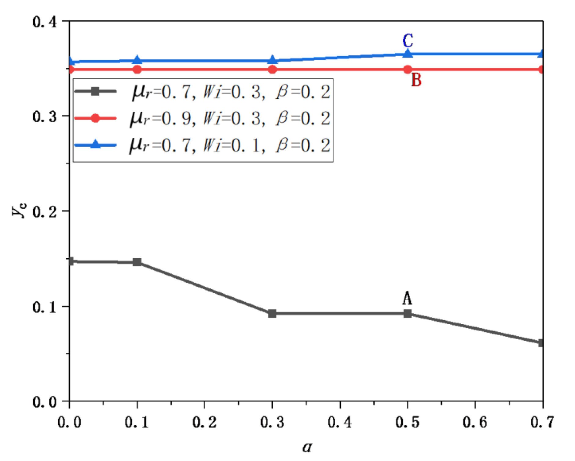
3.2. Effect of the Shear-Thinning Parameterαon the Critical Value yc
α represents the degree of shear-thinning, where large
α corresponds to ahigh degree of shear-thinning.
Figure 6 shows
yc as a function of
α for different values of
μr and Wi. We can see that
yc is larger than 0 regardless of what value the parameter takes, indicating that particles may migrate to the wall or to the centerline. For the fluid without shear-thinning effect (
α = 0), the values of
yc are 0.147, 0.35, and 0.357, respectively. For the case of
μr = 0.9 and Wi = 0.3, as shown in red line, the values of
yc remain 0.35, i.e., the particle with
y0 < 0.35 and
y0 ≥ 0.35 will migrate towards the centerline and wall, respectively. Moreover, the value of
yc is independent of
α. For the case of
μr = 0.7 and Wi = 0.3 (black line), the values of
yc are reduced with the increase in
α, i.e., the particle is more likely to move towards the wall at large
α. For example, the particle with
α = 0 will migrate towards the wall when
y0 > 0.147, while the particle with
α = 0.7 will migrate towards the wall when
y0 > 0.061. For fixed
μr, the value of
yc increases with decreasing Wi (comparing black line and blue line); for fixed Wi, the value of
yc increases with increasing
μr, that is, particle is more likely to migrate towards the center line at small Wi and large
μr.
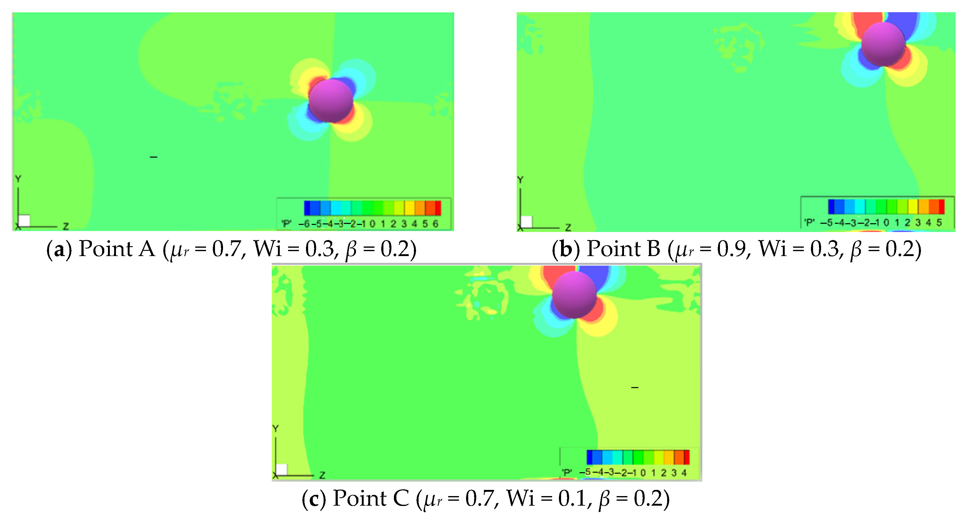
Figure 7 displays the pressure contours at three cases in
Figure 6. The explanation of the figure is the same as that of
Figure 5. We can see that large red areas (large positive pressure) and large blue areas (large negative pressure) appear around the particle near the wall, showing that the particle near the wall will migrate faster because the particle will migrate towards the area with lower pressure at the next moment.
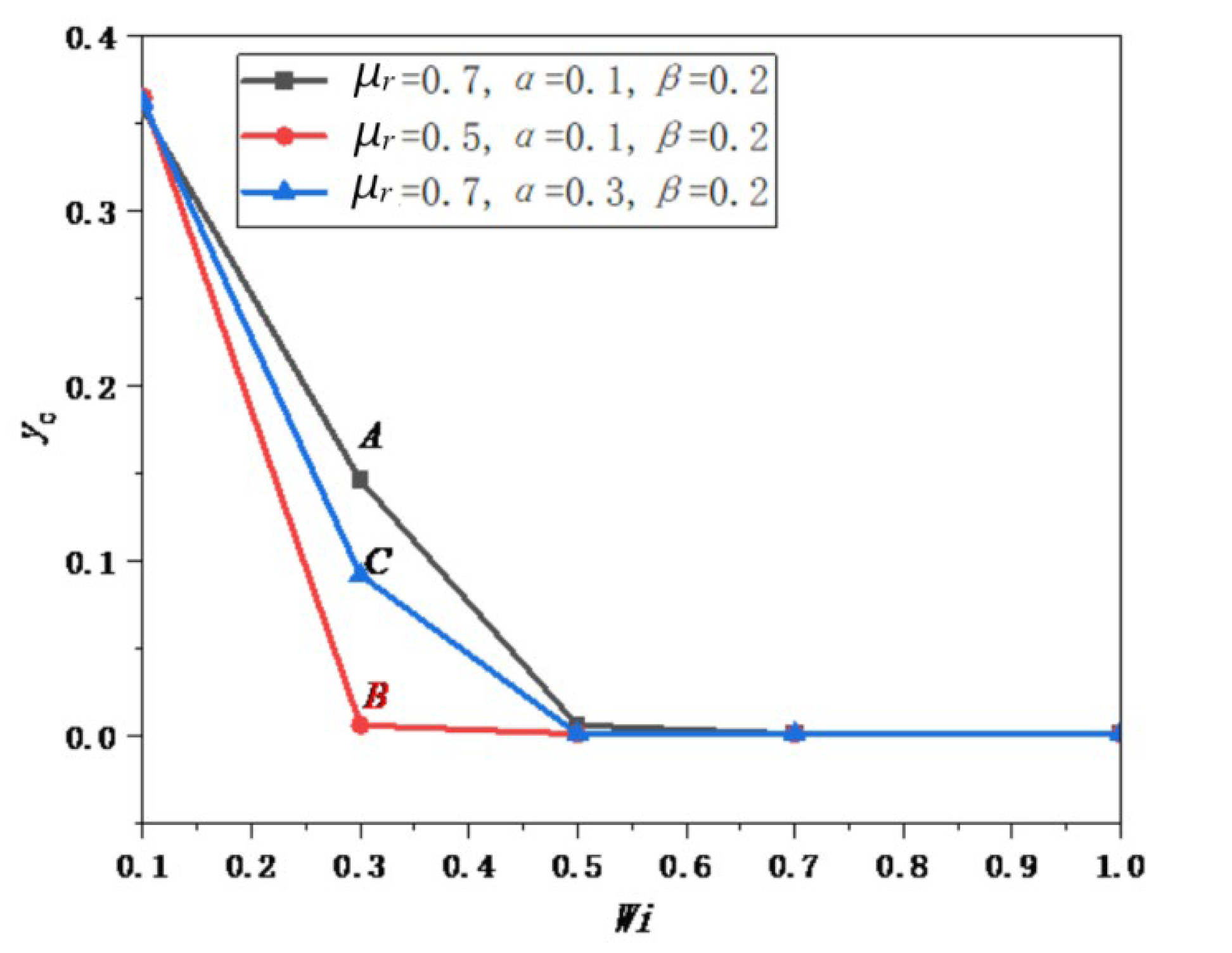
3.3. Effect of the Weissenberg Number Wi on the Critical Value yc
Wi is used for representing the relative importance of elastic and viscous force [
25].
Figure 8 displays
yc as a function of Wi for different
μr and
α. It can be seen that the values of
yc are large (from 0.358 to 0.365) at Wi = 0.1, while they are small (≤ 0.006) for 0.5 < Wi < 1.0; the values of
yc decrease with the increase in Wi in the range of 0.1 < Wi < 0.5, indicating that the particle is more inclined to migrate towards the wall with the increases in Wi, and the effect of Wi on the particle migration direction is obvious. For fixed
α, the value of
yc rises with the increase in
μr; for fixed
μr, the value of
yc rises with the decrease in
α. Therefore, the particle is more likely to move towards the wall at small
μr and large
α.
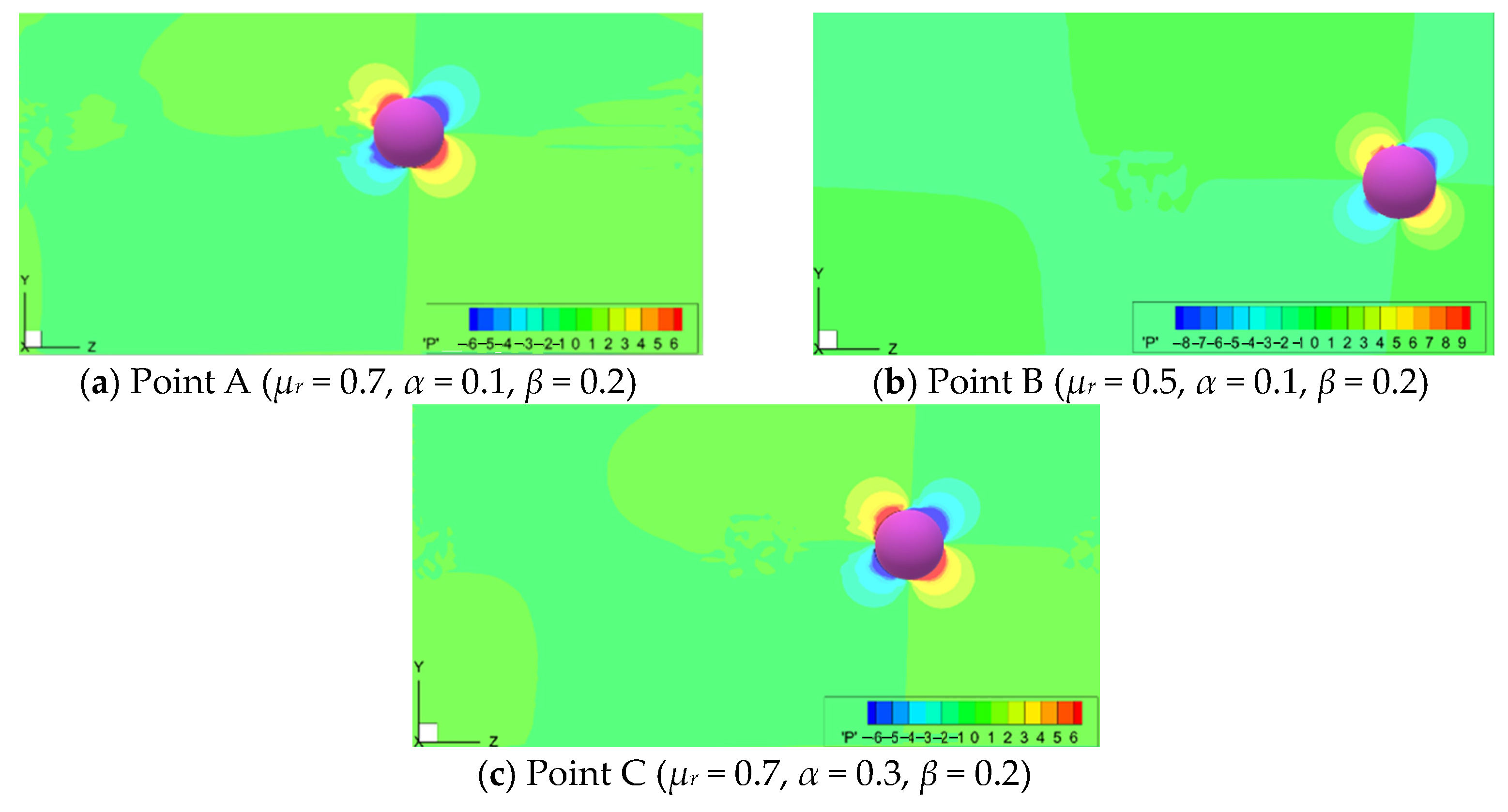
The pressure contours for three cases in
Figure 8 are shown in
Figure 9. The description of the figure is the same as that of
Figure 5. We can see that the particle in the three figures is located between the wall and the centerline, the pressure distributions are similar, i.e., the upper left corner and lower right corner have larger pressure, while the upper right corner and upper left corner have less pressure.
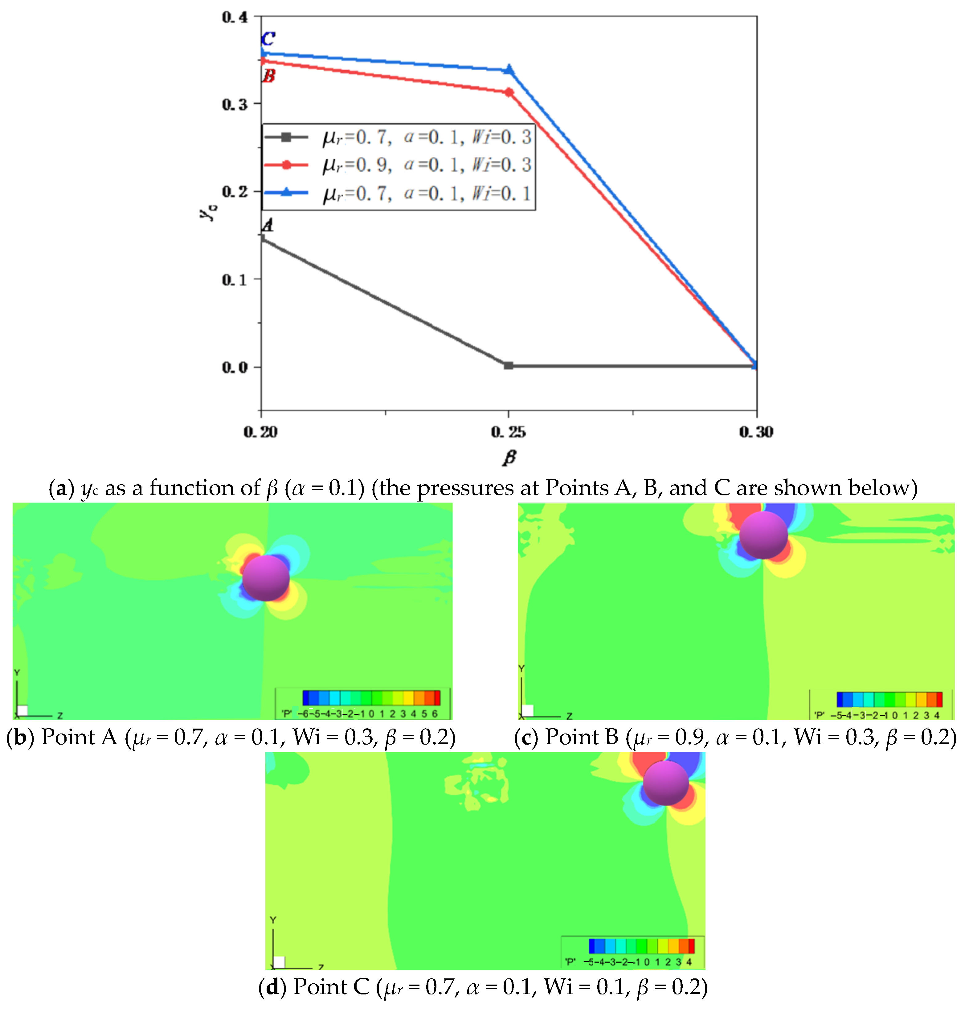
3.4. Effect of the Blocking Rateβ on the Critical Value yc
yc as a function of
β for different values of
μr and Wi is given in
Figure 10a, where we can see that
β has a large effect on the particle migration direction. For
β = 0.2, the values of
yc are 0.146 (Point A), 0.35 (Point B), and 0.358 (Point C), while the values of
yc are 0.001 for the three cases at
β = 0.3, i.e., particle will migrate towards the wall for
β = 0.3. The values of
yc decrease with the increase in
β, although the change trend of
yc with
β is different under different parameters. The particle is more inclined to migrate towards the wall with the increase in
β. For fixed
μr, the value of
yc increases with decreasing Wi; for fixed Wi, the value of
yc rises with increasing
μr. Therefore, the particle is more inclined to migrate towards the wall at large Wi and small
μr.
Figure 10b–d shows the pressure contours for three cases in
Figure 10a. The pressure distribution in
Figure 10b–d is similar to that in
Figure 7, that is, large positive pressure and large negative pressure appear around the particle near the wall surface so that the particle near the wall will migrate faster.


